EP3483977B1 - Batterieausrichtungsvorrichtung - Google Patents
Batterieausrichtungsvorrichtung Download PDFInfo
- Publication number
- EP3483977B1 EP3483977B1 EP18205872.7A EP18205872A EP3483977B1 EP 3483977 B1 EP3483977 B1 EP 3483977B1 EP 18205872 A EP18205872 A EP 18205872A EP 3483977 B1 EP3483977 B1 EP 3483977B1
- Authority
- EP
- European Patent Office
- Prior art keywords
- battery
- cylindrical battery
- cylindrical
- aligning device
- end portion
- Prior art date
- Legal status (The legal status is an assumption and is not a legal conclusion. Google has not performed a legal analysis and makes no representation as to the accuracy of the status listed.)
- Active
Links
Images

Classifications
-
- B—PERFORMING OPERATIONS; TRANSPORTING
- B65—CONVEYING; PACKING; STORING; HANDLING THIN OR FILAMENTARY MATERIAL
- B65G—TRANSPORT OR STORAGE DEVICES, e.g. CONVEYORS FOR LOADING OR TIPPING, SHOP CONVEYOR SYSTEMS OR PNEUMATIC TUBE CONVEYORS
- B65G11/00—Chutes
- B65G11/20—Auxiliary devices, e.g. for deflecting, controlling speed of, or agitating articles or solids
- B65G11/203—Auxiliary devices, e.g. for deflecting, controlling speed of, or agitating articles or solids for articles
-
- H—ELECTRICITY
- H01—ELECTRIC ELEMENTS
- H01M—PROCESSES OR MEANS, e.g. BATTERIES, FOR THE DIRECT CONVERSION OF CHEMICAL ENERGY INTO ELECTRICAL ENERGY
- H01M6/00—Primary cells; Manufacture thereof
- H01M6/50—Methods or arrangements for servicing or maintenance, e.g. for maintaining operating temperature
- H01M6/5011—Methods or arrangements for servicing or maintenance, e.g. for maintaining operating temperature for several cells simultaneously or successively
-
- B—PERFORMING OPERATIONS; TRANSPORTING
- B65—CONVEYING; PACKING; STORING; HANDLING THIN OR FILAMENTARY MATERIAL
- B65G—TRANSPORT OR STORAGE DEVICES, e.g. CONVEYORS FOR LOADING OR TIPPING, SHOP CONVEYOR SYSTEMS OR PNEUMATIC TUBE CONVEYORS
- B65G47/00—Article or material-handling devices associated with conveyors; Methods employing such devices
- B65G47/34—Devices for discharging articles or materials from conveyor
- B65G47/44—Arrangements or applications of hoppers or chutes
-
- H—ELECTRICITY
- H01—ELECTRIC ELEMENTS
- H01M—PROCESSES OR MEANS, e.g. BATTERIES, FOR THE DIRECT CONVERSION OF CHEMICAL ENERGY INTO ELECTRICAL ENERGY
- H01M10/00—Secondary cells; Manufacture thereof
- H01M10/42—Methods or arrangements for servicing or maintenance of secondary cells or secondary half-cells
- H01M10/4207—Methods or arrangements for servicing or maintenance of secondary cells or secondary half-cells for several batteries or cells simultaneously or sequentially
-
- H—ELECTRICITY
- H01—ELECTRIC ELEMENTS
- H01M—PROCESSES OR MEANS, e.g. BATTERIES, FOR THE DIRECT CONVERSION OF CHEMICAL ENERGY INTO ELECTRICAL ENERGY
- H01M10/00—Secondary cells; Manufacture thereof
- H01M10/42—Methods or arrangements for servicing or maintenance of secondary cells or secondary half-cells
- H01M10/44—Methods for charging or discharging
-
- Y—GENERAL TAGGING OF NEW TECHNOLOGICAL DEVELOPMENTS; GENERAL TAGGING OF CROSS-SECTIONAL TECHNOLOGIES SPANNING OVER SEVERAL SECTIONS OF THE IPC; TECHNICAL SUBJECTS COVERED BY FORMER USPC CROSS-REFERENCE ART COLLECTIONS [XRACs] AND DIGESTS
- Y02—TECHNOLOGIES OR APPLICATIONS FOR MITIGATION OR ADAPTATION AGAINST CLIMATE CHANGE
- Y02E—REDUCTION OF GREENHOUSE GAS [GHG] EMISSIONS, RELATED TO ENERGY GENERATION, TRANSMISSION OR DISTRIBUTION
- Y02E60/00—Enabling technologies; Technologies with a potential or indirect contribution to GHG emissions mitigation
- Y02E60/10—Energy storage using batteries
Definitions
- the present invention relates to a device for aligning batteries.
- a secondary battery charging device configured such that each of the secondary batteries is charged automatically is proposed.
- a secondary battery charging device including a hopper for accommodating a large number of secondary batteries and a rotating barrel which receives the secondary batteries accommodated in the hopper one by one in a slot and transfers them to a charging position is disclosed.
- directions of the secondary batteries in the hopper need to be aligned so as to make them in parallel with a rotary shaft of the rotating barrel so that the slot can accommodate the secondary battery. That is, if secondary batteries which are not aligned in the direction are conveyed to each of the slots, the rotating barrel cannot transfer the secondary batteries, which could cause a failure or abnormal stop.
- the batteries are aligned in a predetermined direction in a conveying process of the battery by vibrating a sieve constituted by arranging a plurality of elongated rectangular plates at a predetermined interval by a power mechanism.
- the present invention has been made in view of such circumstances and has an object to provide a small-sized and inexpensive battery aligning device.
- a first aspect of the present invention is a battery aligning device which includes an inlet through which a first cylindrical battery is input, an outlet from which the first cylindrical battery is discharged, a plurality of regulating plates constituting a slit in a path from the inlet to the outlet, and a support member which supports one end portion and another end portion of each of the plurality of regulating plates, in which the regulating plate has a length from the one end portion to the other end portion longer than the length of the first cylindrical battery, a cross-section perpendicular to a direction where the one end portion and the other end portion are connected has a non-linear shape, in an interval between one of the two regulating plates and the other regulating plate facing each other, a facing interval between the surfaces is larger than a diameter of the first cylindrical battery, and when a line segment having the same length as that of the first cylindrical battery is in contact with the one regulating plate at two points on the cross-section, a distance between the line segment and the other regulating plate is smaller than the diameter of the first cylindrical
- the plurality of regulating plates included in the battery aligning device has the one end portions and the other end portions supported by the support member from the both sides, has a cross-section perpendicular to a supporting direction with a non-linear shape, and constitutes a slit in the path from the inlet to the outlet.
- the facing interval between the facing surfaces is set larger than the diameter of the first cylindrical battery, if the direction of the longitudinal direction of the input first cylindrical battery is in parallel with the supporting direction, the first cylindrical battery can be discharged from the outlet.
- the plurality of regulating plates is arranged at such interval that the distance between the line segment and the other regulating plate is smaller than the diameter of the first cylindrical battery.
- the battery aligning device can prevent the plurality of first cylindrical batteries from being discharged with the directions being not aligned, and the directions of the plurality of input first cylindrical batteries can be aligned. Then, the battery aligning device does not need any of a mechanism for detecting a direction of the battery, a power mechanism, and a conveying device including a conveyance path. Therefore, according to the first aspect of the present invention, a working effect that a small-sized and inexpensive battery aligning device can be provided is obtained.
- a second aspect of the present invention is, in the aforementioned first aspect of the present invention, a battery aligning device in which, in the interval between the one regulating plate and the other regulating plate, when a line segment having the same length as that of the second cylindrical battery having a dimension smaller than that of the first cylindrical battery is in contact with the one regulating plate at two points on the cross-section, the distance between the line segment and the other regulating plate is smaller than a diameter of the second cylindrical battery.
- the facing interval between the facing surfaces is set larger than the diameter of the first cylindrical battery and thus, if the longitudinal directions of the input first cylindrical battery and second cylindrical battery are in parallel with the supporting direction, the first cylindrical battery and the second cylindrical battery can be discharged from the outlet.
- the plurality of regulating plates is arranged at such interval that the distance between the line segment and the other regulating plate is smaller than the diameter of the second cylindrical battery.
- the battery aligning device 1 can prevent the plurality of first cylindrical batteries and second cylindrical batteries from being discharged with the directions being not aligned, and the directions of the plurality of input first cylindrical batteries and second cylindrical batteries can be aligned. Then, the battery aligning device 1 does not need any of a mechanism for detecting a direction of the battery, a power mechanism, and a conveying device including a conveyance path. Therefore, according to the second aspect of the present invention, a working effect that a small-sized and inexpensive battery aligning device can be provided is obtained.
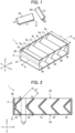
- FIG. 1 is a perspective view of the battery aligning device 1 according to the first embodiment of the present invention.
- the battery aligning device 1 when a plurality of cylindrical batteries oriented in various directions is input, the directions of those cylindrical batteries are aligned and discharged.
- two types of batteries that is, a first cylindrical battery B1 and a second cylindrical battery B2 can be input.
- the first cylindrical battery B1 is a size AA battery, for example, in this embodiment and has a length L1 in a longitudinal direction of 50 mm and a diameter D1 of 14.5 mm.
- the second cylindrical battery B2 has a dimension smaller than that of the first cylindrical battery B1 and is a size AAA battery, for example, in this embodiment and has a length L2 in the longitudinal direction of 45 mm and a diameter D1 of 10. 5 mm.
- the battery to be input into the battery aligning device 1 may be either the first cylindrical battery B1 or the second cylindrical battery B2.
- the battery aligning device 1 includes a support member 2 and a plurality of regulating plates 3a to 3e.
- a support member 2 and a plurality of regulating plates 3a to 3e.
- directions orthogonal to each other in a horizontal direction are assumed to be an X-direction and a Y-direction, respectively, and a vertical direction as a Z-direction.
- the support member 2 is a frame body which surrounds four sides in the X-direction and the Y-direction by plate-shaped members in this embodiment, a region in an X-Y plane surrounded by an upper end portion 20 in the Z-direction is formed as an inlet 22, and a region in the X-Y plane surrounded by a lower end portion 21 in the Z-direction is formed as an outlet 23 (both of them are not shown in FIG. 1 ) .
- Each of the plurality of regulating plates 3a to 3e is plate-shaped member having a length L in the Y-direction, and one end portion 30 and the other end portion 31 are supported by the support member 2 from both sides in the Y-direction. Moreover, each of the regulating plates 3a to 3e has an L-shaped cross-section on an X-Z plane in this embodiment, whose details will be described later.
- the number of the regulating plates only needs to be plural and is not limited to the number of the regulating plates 3a to 3e, that is, five.
- the support member 2 and the regulating plates 3a to 3e are formed by molding a resin in this embodiment but may be formed of other materials such as metal or wood, for example.
- the regulating plates 3a to 3e are formed so that the length L in the Y-direction is longer than the length L1 of the first cylindrical battery B1.
- the length L is set to 70 mm.
- the length L of the battery aligning device 1 may be set longer than the length L2 of the second cylindrical battery B2.
- FIG. 2 is a cross-sectional view of the battery aligning device 1 according to the first embodiment of the present invention. Specifically, FIG. 2 is a cross-sectional view of the X-Z plane indicated by II-II in FIG. 1 and illustrates a cross-section perpendicular to the Y-direction where the one end portion 30 and the other end portion 31 of each of the plurality of regulating plates 3a to 3e are connected.
- the regulating plates 3a to 3e are arranged at an equal interval so that the surfaces facing each other are in parallel and are separated away in the X-direction. Since each of the regulating plates 3a to 3e is arranged having the same shape and in the same direction, the regulating plate 3a and the regulating plate 3b will be described in detail herein, and detailed description for the regulating plates 3c to 3e is omitted.
- the regulating plate 3a is a bent flat plate having an upstream end portion A on the inlet 22 side and a downstream end portion C on the outlet 23 side as both ends with respect to the Z-direction and having a bending point B between the upstream end portion A and the downstream end portion C and has an L-shaped cross-section in the X-Z plane, that is, a non-linear shape.
- the upstream end portion A and the downstream end portion C are matched with positions of the inlet 22 and the outlet 23, respectively, in this embodiment, but the inlet 22 and the outlet 23 may be at different positions, respectively, with respect to the Z-direction.
- the regulating plate 3b is a bent flat plate having an upstream end portion D on the inlet 22 side and a downstream end portion F on the outlet 23 side as both ends in the Z-direction and having a bending point E between the upstream end portion D and the downstream end portion F and has an L-shaped cross-section in the X-Z plane.
- a facing interval J1 is set larger than the diameter D1 of the first cylindrical battery B1.
- a lower limit value is set to the interval between the regulating plate 3a and the regulating plate 3b so that the facing interval J1 between a straight line AB going through the upstream end portion A of the regulating plate 3a and the bending point B and a straight line DE going through the upstream end portion D of the regulating plate 3b and the bending point E is larger than the diameter D1.
- the facing interval J1 is set to 15 mm.
- the facing interval J1 may be set to an interval larger than a diameter D2 of the second cylindrical battery B2.
- a slit causing the inlet 22 and the outlet 23 to linearly communicate with each other is formed.
- a slit interval J2 is formed by a straight line AC going through the upstream end portion A and the downstream end portion C of the regulating plate 3a and a straight line in parallel with the straight line AC and going through the bending point E of the regulating plate 3b.
- an upper limit value is set to the interval between the regulating plate 3a and the regulating plate 3b so that the slit interval J2 becomes an interval smaller than the diameter D2 of the second cylindrical battery B2.
- the slit interval J2 is set to 9 mm.
- the slit interval J2 may be set to an interval smaller than the diameter D1 of the first cylindrical battery B1.
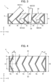
- FIG. 3 is a conceptual diagram illustrating an effect of the present invention.
- FIG. 3 is a cross-sectional view of the battery aligning device 1 schematically illustrating a difference in behaviors of the respective batteries with respect to the directions of the respective batteries when the plurality of first cylindrical batteries B1 and second cylindrical batteries B2 are input into the inlet 22.
- the first cylindrical battery B1 When the longitudinal direction of the first cylindrical battery B1 is in the X-Z plane, due to the shape and arrangement of the regulating plate 3a and the regulating plate 3b as indicated by a state C1 in FIG. 3 , for example, the first cylindrical battery B1 is restrained from passing through the slit. On the other hand, if the longitudinal direction of the first cylindrical battery B1 is oriented in the Y-direction, the first cylindrical battery B1 rolls between the regulating plate 3b and the regulating plate 3c and can pass through a path from the inlet 22 to the outlet 23 as indicated by a state C2 in FIG. 3 , for example, and is discharged from the outlet 23.
- the second cylindrical battery B2 when the longitudinal direction of the second cylindrical battery B2 is in the X-Z plane, due to the shape and arrangement of the regulating plate 3c and the regulating plate 3d as indicated by a state C3 in FIG. 3 , for example, the second cylindrical battery B2 is restrained from passing through the slit.
- the longitudinal direction of the second cylindrical battery B2 if the longitudinal direction of the second cylindrical battery B2 is oriented in the Y-direction, the second cylindrical battery B2 rolls between the regulating plate 3d and the regulating plate 3e and can pass through a path from the inlet 22 to the outlet 23 as indicated by a state C4 in FIG. 3 , for example, and is discharged from the outlet 23.
- the first cylindrical battery B1 and the second cylindrical battery B2 brought into the state C1 and the state C3 in FIG. 3 are discharged from the outlet 23 by manually changing the direction of each of the batteries so that the states are changed to the state C2 and the state C4, respectively.
- a separation interval among the plurality of regulating plates 3a to 3e is set to an interval which prevents the first cylindrical battery B1 and the second cylindrical battery B2 from passing through a path from the inlet 22 to the outlet 23 while changing their longitudinal directions in the X-Z plane. More specifically, as illustrated in the state C3 in FIG.
- a distance between the line segment PQ and the regulating plate 3d may be set smaller than the diameter D1 of the first cylindrical battery B1.
- a distance H1 from the upstream end portion to the downstream end portion is preferably set smaller than the length L2 of the second cylindrical battery B2. That is, if the distance H1 is smaller than the length L2, since the slit interval J2 illustrated in FIG. 2 is set smaller than the diameter D2 of the second cylindrical battery B2 as described above, conditions for preventing the first cylindrical battery B1 and the second cylindrical battery B2 from passing through the path to the outlet 23 while their longitudinal directions remain in the X-Z plane are satisfied.
- the battery aligning device 1 includes the plurality of regulating plates 3a to 3e in the path from the inlet 22 to the outlet 23, and the cross-section in the X-Z plane has a non-linear shape. Moreover, the battery aligning device 1 is arranged such that the facing interval J1 between the surfaces of the plurality of facing regulating plates 3a to 3e is larger than the diameter of the first cylindrical battery B1, and the slit interval J2 is smaller than the diameter of the second cylindrical battery B2.
- the battery aligning device 1 if the direction of the longitudinal direction of the input battery is in the X-Z plane, the battery is restrained from passing through the path to the outlet 23, while if it is in the Y-direction, the battery is discharged from the outlet 23.
- the battery aligning device 1 can discharge the battery in the predetermined direction even if the plurality of batteries that is not aligned in the direction is input.
- the battery aligning device 1 does not need any of a mechanism for detecting the direction of the battery, a power mechanism, and a conveying device including a conveyance path, and the plurality of input batteries passes through the path to the outlet 23 by its own weight and moreover, it has configuration that does not include a power mechanism or a mechanism or the like which may cause a failure. Therefore, according to the present invention, a small-sized and inexpensive battery aligning device can be provided.
- a battery aligning device 4 according to a second embodiment of the present invention will be described.
- the battery aligning device 4 similarly to the battery aligning device 1 according to the aforementioned first embodiment, when the plurality of first cylindrical batteries B1 and second cylindrical batteries B2 oriented in various directions is input, the battery aligning device 4 aligns those cylindrical batteries and then, discharges them.
- FIG. 4 is a cross-sectional view of the battery aligning device 4 according to the second embodiment of the present invention.
- the battery aligning device 4 includes a support member 5 and a plurality of regulating plates 6a to 6f, both having distances in the Z-direction of H2.
- the plurality of regulating plates 6a to 6f has L-shaped cross-sections in the X-Z plane, but the bending angle is an obtuse angle.
- the distance H2 of the plurality of regulating plates 6a to 6f in the Z-direction is longer than the length L2 of the second cylindrical battery B2.
- the facing interval J1 between the facing surfaces of the plurality of regulating plates 6a to 6f is set to an interval larger than the diameter D1 of the first cylindrical battery B1 similarly to the aforementioned first embodiment.
- a separation interval among the plurality of regulating plates 6a to 6f is set to an interval which prevents the first cylindrical battery B1 and the second cylindrical battery B2 from passing through the path from the inlet 52 to the outlet 53 while changing their longitudinal directions in the X-Z plane. More specifically, as illustrated in FIG. 4 , for example, in the interval between the regulating plate 6a as the "one regulating plate” and the regulating plate 6b as the “other regulating plate” facing each other, when a line segment ST having the same length as that of the second cylindrical battery B2 is in contact at two points, that is, a point S and a point T, a distance J3 between the line segment ST and the regulating plate 6b is set smaller than the diameter D2 of the second cylindrical battery B2. As a result, the first cylindrical battery B1 and the second cylindrical battery B2 are prevented from passing through the path to the outlet 23 as long as their longitudinal directions is in the X-Z plane.
- a small-sized and inexpensive battery aligning device can be provided similarly to the battery aligning device 1 according to the first embodiment of the present invention described above.
- the battery aligning device 4 according to this embodiment since the bending angle of the regulating plates 6a to 6f can be made an obtuse angle, even if there is a limit on a dimension in the X-direction, the number of paths from the inlet 52 to the outlet 53 can be increased within a range of the limit.
- each of the plurality of regulating plates 3a to 3e in the X-Z plane has an L-shape but it may be a C-shape as the plurality of regulating plates 3a' to 3e' illustrated in FIG. 5 .
- the plurality of regulating plates 3a to 3e has a vertically symmetric shape with respect to the Z-direction, but they may have a vertically asymmetric shape.
Landscapes
- Engineering & Computer Science (AREA)
- Manufacturing & Machinery (AREA)
- Chemical & Material Sciences (AREA)
- Chemical Kinetics & Catalysis (AREA)
- Electrochemistry (AREA)
- General Chemical & Material Sciences (AREA)
- Mechanical Engineering (AREA)
- Battery Mounting, Suspending (AREA)
- Sealing Battery Cases Or Jackets (AREA)
Claims (2)
- Batterieausrichtungsvorrichtung (1, 4) umfassend:einen Einlass (22), durch den hindurch eine erste zylindrische Batterie (B1, B2) eingelassen wird;einen Auslass (23), aus dem heraus die erste zylindrische Batterie (B1, B2) entladen wird;mehrere Regulierplatten (3a - 3e), die mehrere Schlitze in einem Pfad vom Einlass (22) zum Auslass (23) bilden; undein Tragteil (2), das einen Endabschnitt (30) und einen anderen Endabschnitt (31) jeder der mehreren Regulierplatten (3a - 3e) trägt, wobeialle Regulierplatten (3a - 3e) eine Länge (L) von dem einem Endabschnitt (30) zum anderen Endabschnitt (31) umfassen, die länger ist als eine Länge (L1, L2) der ersten zylindrischen Batterie (B1, B2), und einen Querschnitt senkrecht zu einer Richtung umfasst, in welcher der eine Endabschnitt (30) und der andere Endabschnitt (31) verbunden sind, der eine nichtlineare Form hat; wobeialle zugewandten Zwischenräume (J1) zwischen zwei angrenzenden Regulierplatten (3a - 3e) einen Abstand im Hinblick auf zugewandte Flächen der angrenzenden Regulierplatten (3a - 3e)umfassen, der größer ist als ein Duchmeser (D1, D2) der ersten zylindrischen Batterie (B1, B2); unddie Regulierplatten (3a - 3e) so ausgelegt sind, dass, wenn ein gedachtes Liniensegment (PQ) mit derselben Länge wie derjenigen der ersten zylindrischen Batterie (B1, B2) in Kontakt mit einer der Regulierplatten (3a - 3e) an zwei Punkten (Q, R) am Querschnitt ist, ein Abstand zwischen dem gedachten Liniensegment (PQ) und einer anderen angrenzenden Regulierplatte (3a - 3e) kleiner ist als der Durchmesser (D1, D2) der ersten zylindrischen Batterie (B1, B2).
- Batterieausrichtungsvorrichtung (1, 4) nach Anspruch 1, wobei die Regulierplatten (3a - 3e) so ausgelegt sind, dass
alle zugewandten Zwischenräune (J2) zwischen zwei angrenzenden Regulierplatten (3a - 3e), wenn ein gedachtes Liniensegment (PQ) mit derselben Länge wie derjenigen der zweiten zylindrischen Batterie (B1, B2), mit einer Abmessung, die kleiner ist als diejenige der ersten zylindrischen Batterie (B1, B2), in Kontakt mit einer der Regulierplatten (3a - 3e) an zwei Punkten (R, Q) am Querschnitt ist, ein Abstand zwischen dem gedachten Liniensegment (PQ) und einer anderen angrenzenden Regulierplatte (3a - 3e) kleiner ist als ein Durchmesser (D1, D2) der zweiten zylindrischen Batterie (B1, B2).
Applications Claiming Priority (1)
| Application Number | Priority Date | Filing Date | Title |
|---|---|---|---|
| JP2017219277A JP7037920B2 (ja) | 2017-11-14 | 2017-11-14 | 電池整列装置 |
Publications (2)
| Publication Number | Publication Date |
|---|---|
| EP3483977A1 EP3483977A1 (de) | 2019-05-15 |
| EP3483977B1 true EP3483977B1 (de) | 2023-10-04 |
Family
ID=64308590
Family Applications (1)
| Application Number | Title | Priority Date | Filing Date |
|---|---|---|---|
| EP18205872.7A Active EP3483977B1 (de) | 2017-11-14 | 2018-11-13 | Batterieausrichtungsvorrichtung |
Country Status (3)
| Country | Link |
|---|---|
| US (1) | US10414589B2 (de) |
| EP (1) | EP3483977B1 (de) |
| JP (1) | JP7037920B2 (de) |
Families Citing this family (1)
| Publication number | Priority date | Publication date | Assignee | Title |
|---|---|---|---|---|
| US11342620B2 (en) * | 2019-03-04 | 2022-05-24 | Chongqing Jinkang Powertrain New Energy Co., Ltd. | Battery module scalable in three dimensions |
Family Cites Families (22)
| Publication number | Priority date | Publication date | Assignee | Title |
|---|---|---|---|---|
| US1138245A (en) * | 1913-02-03 | 1915-05-04 | Stone J & Co Ltd | Device for sorting and feeding refuse. |
| US3556296A (en) * | 1969-02-13 | 1971-01-19 | Anthony T Buscemi Jr | Beauty parlor accessories |
| US4086695A (en) * | 1974-09-12 | 1978-05-02 | Chloride Connrex Corporation | Methods for the in-situ casting of inter-cell connectors |
| SE451432B (sv) * | 1983-06-15 | 1987-10-12 | Rudolf Woode | Spaltsall for storleksuppdelning av styckeformigt gods, t ex treflis efter dess tjocklek |
| JPS60161777A (ja) | 1984-01-31 | 1985-08-23 | 株式会社荏原製作所 | 乾電池分別装置 |
| JPS6224173A (ja) | 1985-07-24 | 1987-02-02 | Aloka Co Ltd | デジタル計数率計 |
| JPH043715A (ja) * | 1990-04-18 | 1992-01-08 | Shinichi Mori | 部品整列装置 |
| US5077514A (en) * | 1990-09-28 | 1991-12-31 | Motorola, Inc. | Battery charging apparatus and method |
| JP2964612B2 (ja) * | 1990-10-19 | 1999-10-18 | 松下電器産業株式会社 | 円筒型電池の姿勢揃え方法及び装置 |
| US5431575A (en) * | 1994-02-18 | 1995-07-11 | Cardiac Evaluation Center, Inc. | Bi-directional battery holder |
| US5531312A (en) * | 1994-10-24 | 1996-07-02 | Dickey; Daniel M. | Apparatus and method for singulating articles |
| JP3191237B2 (ja) * | 1995-05-31 | 2001-07-23 | 旭精機工業株式会社 | ワーク整列供給装置 |
| JP2000285889A (ja) * | 1999-03-29 | 2000-10-13 | Sony Corp | 円筒形電池の整列方法及び整列治具 |
| JP2001017924A (ja) * | 1999-07-08 | 2001-01-23 | F D K Eng:Kk | 変形缶選別装置 |
| JP4849202B2 (ja) * | 2005-05-17 | 2012-01-11 | 泰三 山本 | 扁平錠剤の外観検査装置 |
| DE102007015672B3 (de) * | 2007-03-31 | 2008-11-27 | Fette Gmbh | Vorrichtung für den Ablauf von Preßlingen aus einer Rundläuferpresse |
| US8602195B2 (en) * | 2008-01-02 | 2013-12-10 | Deltronic Labs, Inc. | Bottle receiving and detection apparatus and method therefore |
| JP2011036774A (ja) * | 2009-08-10 | 2011-02-24 | Jfe Kankyo Corp | 乾電池の選別方法及び選別装置 |
| JP5594264B2 (ja) * | 2011-09-06 | 2014-09-24 | トヨタ自動車株式会社 | 二次電池の拘束装置 |
| WO2013181386A1 (en) * | 2012-06-01 | 2013-12-05 | The Gillette Company | Battery-charging device and method of charging batteries |
| JP5625153B2 (ja) * | 2013-02-08 | 2014-11-19 | 三蓉エンジニアリング株式会社 | 乾電池の選別装置 |
| CN105052222B (zh) | 2013-08-23 | 2019-06-21 | 华为技术有限公司 | 一种用于传输上行信息的方法及装置 |
-
2017
- 2017-11-14 JP JP2017219277A patent/JP7037920B2/ja active Active
-
2018
- 2018-11-13 EP EP18205872.7A patent/EP3483977B1/de active Active
- 2018-11-14 US US16/191,217 patent/US10414589B2/en not_active Expired - Fee Related
Also Published As
| Publication number | Publication date |
|---|---|
| JP7037920B2 (ja) | 2022-03-17 |
| JP2019091612A (ja) | 2019-06-13 |
| US20190144207A1 (en) | 2019-05-16 |
| EP3483977A1 (de) | 2019-05-15 |
| US10414589B2 (en) | 2019-09-17 |
Similar Documents
| Publication | Publication Date | Title |
|---|---|---|
| EP3483977A1 (de) | Batterieausrichtungsvorrichtung | |
| US20140234100A1 (en) | Fan device attachment structure | |
| US8074805B2 (en) | Extra-large vibrating screen with duplex statically indeterminate mesh beam | |
| JP5010270B2 (ja) | 紙葉類の集積装置 | |
| JP4008413B2 (ja) | 重量選別装置 | |
| CN117705374A (zh) | 电池氦检系统及方法 | |
| CN108885132B (zh) | 组合计量装置 | |
| CN109249580A (zh) | 分料机构及具有其的供料系统 | |
| CN201997499U (zh) | 电子元件的分选盘及分选机构 | |
| JP2012188290A (ja) | 少なくとも1つの物体を運搬するためのマット、移載装置及び移載方法 | |
| EP1739632A2 (de) | Vorrichtung zur Sortierung von Papiermaterial | |
| CN105215107A (zh) | 一种管件精密加工设备 | |
| CN115676331B (zh) | 输送机及输送系统 | |
| CN215847749U (zh) | 电池固定装置 | |
| CN208796344U (zh) | 暂存装置及介质处理机 | |
| JP5807502B2 (ja) | 鋼板の精整ライン搬送方法 | |
| US20210125465A1 (en) | Medium stacking sheet and medium separating and stacking apparatus including the same | |
| Kongsiriwong et al. | On the number of solutions of the Tarry-Escott problem of degree two and the related problem over some finite fields | |
| CN101602442A (zh) | 偏心调节装置及具有偏心调节装置的薄片材料分离机构 | |
| CN117401354A (zh) | 曲线模块化固定半径输送带的模块和相应的带 | |
| CN206969840U (zh) | 纸张后处理装置 | |
| CN211087368U (zh) | 传输装置以及票证收发设备 | |
| JP5589349B2 (ja) | 紙葉類処理装置 | |
| EP4417945A1 (de) | Kombinationswiegevorrichtung | |
| CN218884871U (zh) | 一种边框形变检测装置及运输装置 |
Legal Events
| Date | Code | Title | Description |
|---|---|---|---|
| PUAI | Public reference made under article 153(3) epc to a published international application that has entered the european phase |
Free format text: ORIGINAL CODE: 0009012 |
|
| STAA | Information on the status of an ep patent application or granted ep patent |
Free format text: STATUS: REQUEST FOR EXAMINATION WAS MADE |
|
| 17P | Request for examination filed |
Effective date: 20181113 |
|
| AK | Designated contracting states |
Kind code of ref document: A1 Designated state(s): AL AT BE BG CH CY CZ DE DK EE ES FI FR GB GR HR HU IE IS IT LI LT LU LV MC MK MT NL NO PL PT RO RS SE SI SK SM TR |
|
| AX | Request for extension of the european patent |
Extension state: BA ME |
|
| STAA | Information on the status of an ep patent application or granted ep patent |
Free format text: STATUS: EXAMINATION IS IN PROGRESS |
|
| 17Q | First examination report despatched |
Effective date: 20200903 |
|
| REG | Reference to a national code |
Ref country code: DE Ref legal event code: R079 Ipc: H01M0010440000 Ref country code: DE Ref legal event code: R079 Ref document number: 602018058579 Country of ref document: DE Free format text: PREVIOUS MAIN CLASS: H01M0010420000 Ipc: H01M0010440000 |
|
| GRAP | Despatch of communication of intention to grant a patent |
Free format text: ORIGINAL CODE: EPIDOSNIGR1 |
|
| STAA | Information on the status of an ep patent application or granted ep patent |
Free format text: STATUS: GRANT OF PATENT IS INTENDED |
|
| RIC1 | Information provided on ipc code assigned before grant |
Ipc: H01M 6/50 20060101ALI20230502BHEP Ipc: H01M 10/42 20060101ALI20230502BHEP Ipc: H01M 10/44 20060101AFI20230502BHEP |
|
| INTG | Intention to grant announced |
Effective date: 20230522 |
|
| P01 | Opt-out of the competence of the unified patent court (upc) registered |
Effective date: 20230517 |
|
| GRAS | Grant fee paid |
Free format text: ORIGINAL CODE: EPIDOSNIGR3 |
|
| GRAA | (expected) grant |
Free format text: ORIGINAL CODE: 0009210 |
|
| STAA | Information on the status of an ep patent application or granted ep patent |
Free format text: STATUS: THE PATENT HAS BEEN GRANTED |
|
| AK | Designated contracting states |
Kind code of ref document: B1 Designated state(s): AL AT BE BG CH CY CZ DE DK EE ES FI FR GB GR HR HU IE IS IT LI LT LU LV MC MK MT NL NO PL PT RO RS SE SI SK SM TR |
|
| REG | Reference to a national code |
Ref country code: GB Ref legal event code: FG4D |
|
| REG | Reference to a national code |
Ref country code: CH Ref legal event code: EP |
|
| REG | Reference to a national code |
Ref country code: IE Ref legal event code: FG4D |
|
| REG | Reference to a national code |
Ref country code: DE Ref legal event code: R096 Ref document number: 602018058579 Country of ref document: DE |
|
| REG | Reference to a national code |
Ref country code: LT Ref legal event code: MG9D |
|
| REG | Reference to a national code |
Ref country code: NL Ref legal event code: MP Effective date: 20231004 |
|
| REG | Reference to a national code |
Ref country code: AT Ref legal event code: MK05 Ref document number: 1618685 Country of ref document: AT Kind code of ref document: T Effective date: 20231004 |
|
| PG25 | Lapsed in a contracting state [announced via postgrant information from national office to epo] |
Ref country code: NL Free format text: LAPSE BECAUSE OF FAILURE TO SUBMIT A TRANSLATION OF THE DESCRIPTION OR TO PAY THE FEE WITHIN THE PRESCRIBED TIME-LIMIT Effective date: 20231004 |
|
| PG25 | Lapsed in a contracting state [announced via postgrant information from national office to epo] |
Ref country code: GR Free format text: LAPSE BECAUSE OF FAILURE TO SUBMIT A TRANSLATION OF THE DESCRIPTION OR TO PAY THE FEE WITHIN THE PRESCRIBED TIME-LIMIT Effective date: 20240105 |
|
| PG25 | Lapsed in a contracting state [announced via postgrant information from national office to epo] |
Ref country code: IS Free format text: LAPSE BECAUSE OF FAILURE TO SUBMIT A TRANSLATION OF THE DESCRIPTION OR TO PAY THE FEE WITHIN THE PRESCRIBED TIME-LIMIT Effective date: 20240204 |
|
| PG25 | Lapsed in a contracting state [announced via postgrant information from national office to epo] |
Ref country code: LT Free format text: LAPSE BECAUSE OF FAILURE TO SUBMIT A TRANSLATION OF THE DESCRIPTION OR TO PAY THE FEE WITHIN THE PRESCRIBED TIME-LIMIT Effective date: 20231004 |
|
| PG25 | Lapsed in a contracting state [announced via postgrant information from national office to epo] |
Ref country code: AT Free format text: LAPSE BECAUSE OF FAILURE TO SUBMIT A TRANSLATION OF THE DESCRIPTION OR TO PAY THE FEE WITHIN THE PRESCRIBED TIME-LIMIT Effective date: 20231004 |
|
| PG25 | Lapsed in a contracting state [announced via postgrant information from national office to epo] |
Ref country code: ES Free format text: LAPSE BECAUSE OF FAILURE TO SUBMIT A TRANSLATION OF THE DESCRIPTION OR TO PAY THE FEE WITHIN THE PRESCRIBED TIME-LIMIT Effective date: 20231004 |
|
| PG25 | Lapsed in a contracting state [announced via postgrant information from national office to epo] |
Ref country code: LT Free format text: LAPSE BECAUSE OF FAILURE TO SUBMIT A TRANSLATION OF THE DESCRIPTION OR TO PAY THE FEE WITHIN THE PRESCRIBED TIME-LIMIT Effective date: 20231004 Ref country code: IS Free format text: LAPSE BECAUSE OF FAILURE TO SUBMIT A TRANSLATION OF THE DESCRIPTION OR TO PAY THE FEE WITHIN THE PRESCRIBED TIME-LIMIT Effective date: 20240204 Ref country code: GR Free format text: LAPSE BECAUSE OF FAILURE TO SUBMIT A TRANSLATION OF THE DESCRIPTION OR TO PAY THE FEE WITHIN THE PRESCRIBED TIME-LIMIT Effective date: 20240105 Ref country code: ES Free format text: LAPSE BECAUSE OF FAILURE TO SUBMIT A TRANSLATION OF THE DESCRIPTION OR TO PAY THE FEE WITHIN THE PRESCRIBED TIME-LIMIT Effective date: 20231004 Ref country code: BG Free format text: LAPSE BECAUSE OF FAILURE TO SUBMIT A TRANSLATION OF THE DESCRIPTION OR TO PAY THE FEE WITHIN THE PRESCRIBED TIME-LIMIT Effective date: 20240104 Ref country code: AT Free format text: LAPSE BECAUSE OF FAILURE TO SUBMIT A TRANSLATION OF THE DESCRIPTION OR TO PAY THE FEE WITHIN THE PRESCRIBED TIME-LIMIT Effective date: 20231004 Ref country code: PT Free format text: LAPSE BECAUSE OF FAILURE TO SUBMIT A TRANSLATION OF THE DESCRIPTION OR TO PAY THE FEE WITHIN THE PRESCRIBED TIME-LIMIT Effective date: 20240205 |
|
| PG25 | Lapsed in a contracting state [announced via postgrant information from national office to epo] |
Ref country code: SE Free format text: LAPSE BECAUSE OF FAILURE TO SUBMIT A TRANSLATION OF THE DESCRIPTION OR TO PAY THE FEE WITHIN THE PRESCRIBED TIME-LIMIT Effective date: 20231004 Ref country code: RS Free format text: LAPSE BECAUSE OF FAILURE TO SUBMIT A TRANSLATION OF THE DESCRIPTION OR TO PAY THE FEE WITHIN THE PRESCRIBED TIME-LIMIT Effective date: 20231004 Ref country code: PL Free format text: LAPSE BECAUSE OF FAILURE TO SUBMIT A TRANSLATION OF THE DESCRIPTION OR TO PAY THE FEE WITHIN THE PRESCRIBED TIME-LIMIT Effective date: 20231004 Ref country code: NO Free format text: LAPSE BECAUSE OF FAILURE TO SUBMIT A TRANSLATION OF THE DESCRIPTION OR TO PAY THE FEE WITHIN THE PRESCRIBED TIME-LIMIT Effective date: 20240104 Ref country code: LV Free format text: LAPSE BECAUSE OF FAILURE TO SUBMIT A TRANSLATION OF THE DESCRIPTION OR TO PAY THE FEE WITHIN THE PRESCRIBED TIME-LIMIT Effective date: 20231004 Ref country code: HR Free format text: LAPSE BECAUSE OF FAILURE TO SUBMIT A TRANSLATION OF THE DESCRIPTION OR TO PAY THE FEE WITHIN THE PRESCRIBED TIME-LIMIT Effective date: 20231004 |
|
| REG | Reference to a national code |
Ref country code: CH Ref legal event code: PL |
|
| REG | Reference to a national code |
Ref country code: DE Ref legal event code: R097 Ref document number: 602018058579 Country of ref document: DE |
|
| PG25 | Lapsed in a contracting state [announced via postgrant information from national office to epo] |
Ref country code: DK Free format text: LAPSE BECAUSE OF FAILURE TO SUBMIT A TRANSLATION OF THE DESCRIPTION OR TO PAY THE FEE WITHIN THE PRESCRIBED TIME-LIMIT Effective date: 20231004 |
|
| PG25 | Lapsed in a contracting state [announced via postgrant information from national office to epo] |
Ref country code: LU Free format text: LAPSE BECAUSE OF NON-PAYMENT OF DUE FEES Effective date: 20231113 |
|
| PG25 | Lapsed in a contracting state [announced via postgrant information from national office to epo] |
Ref country code: CH Free format text: LAPSE BECAUSE OF NON-PAYMENT OF DUE FEES Effective date: 20231130 |
|
| PG25 | Lapsed in a contracting state [announced via postgrant information from national office to epo] |
Ref country code: CZ Free format text: LAPSE BECAUSE OF FAILURE TO SUBMIT A TRANSLATION OF THE DESCRIPTION OR TO PAY THE FEE WITHIN THE PRESCRIBED TIME-LIMIT Effective date: 20231004 |
|
| PG25 | Lapsed in a contracting state [announced via postgrant information from national office to epo] |
Ref country code: SK Free format text: LAPSE BECAUSE OF FAILURE TO SUBMIT A TRANSLATION OF THE DESCRIPTION OR TO PAY THE FEE WITHIN THE PRESCRIBED TIME-LIMIT Effective date: 20231004 |
|
| PG25 | Lapsed in a contracting state [announced via postgrant information from national office to epo] |
Ref country code: SM Free format text: LAPSE BECAUSE OF FAILURE TO SUBMIT A TRANSLATION OF THE DESCRIPTION OR TO PAY THE FEE WITHIN THE PRESCRIBED TIME-LIMIT Effective date: 20231004 Ref country code: SK Free format text: LAPSE BECAUSE OF FAILURE TO SUBMIT A TRANSLATION OF THE DESCRIPTION OR TO PAY THE FEE WITHIN THE PRESCRIBED TIME-LIMIT Effective date: 20231004 Ref country code: RO Free format text: LAPSE BECAUSE OF FAILURE TO SUBMIT A TRANSLATION OF THE DESCRIPTION OR TO PAY THE FEE WITHIN THE PRESCRIBED TIME-LIMIT Effective date: 20231004 Ref country code: LU Free format text: LAPSE BECAUSE OF NON-PAYMENT OF DUE FEES Effective date: 20231113 Ref country code: IT Free format text: LAPSE BECAUSE OF FAILURE TO SUBMIT A TRANSLATION OF THE DESCRIPTION OR TO PAY THE FEE WITHIN THE PRESCRIBED TIME-LIMIT Effective date: 20231004 Ref country code: EE Free format text: LAPSE BECAUSE OF FAILURE TO SUBMIT A TRANSLATION OF THE DESCRIPTION OR TO PAY THE FEE WITHIN THE PRESCRIBED TIME-LIMIT Effective date: 20231004 Ref country code: DK Free format text: LAPSE BECAUSE OF FAILURE TO SUBMIT A TRANSLATION OF THE DESCRIPTION OR TO PAY THE FEE WITHIN THE PRESCRIBED TIME-LIMIT Effective date: 20231004 Ref country code: CZ Free format text: LAPSE BECAUSE OF FAILURE TO SUBMIT A TRANSLATION OF THE DESCRIPTION OR TO PAY THE FEE WITHIN THE PRESCRIBED TIME-LIMIT Effective date: 20231004 Ref country code: CH Free format text: LAPSE BECAUSE OF NON-PAYMENT OF DUE FEES Effective date: 20231130 |
|
| REG | Reference to a national code |
Ref country code: BE Ref legal event code: MM Effective date: 20231130 |
|
| PLBE | No opposition filed within time limit |
Free format text: ORIGINAL CODE: 0009261 |
|
| STAA | Information on the status of an ep patent application or granted ep patent |
Free format text: STATUS: NO OPPOSITION FILED WITHIN TIME LIMIT |
|
| PG25 | Lapsed in a contracting state [announced via postgrant information from national office to epo] |
Ref country code: MC Free format text: LAPSE BECAUSE OF FAILURE TO SUBMIT A TRANSLATION OF THE DESCRIPTION OR TO PAY THE FEE WITHIN THE PRESCRIBED TIME-LIMIT Effective date: 20231004 |
|
| PG25 | Lapsed in a contracting state [announced via postgrant information from national office to epo] |
Ref country code: MC Free format text: LAPSE BECAUSE OF FAILURE TO SUBMIT A TRANSLATION OF THE DESCRIPTION OR TO PAY THE FEE WITHIN THE PRESCRIBED TIME-LIMIT Effective date: 20231004 |
|
| 26N | No opposition filed |
Effective date: 20240705 |
|
| REG | Reference to a national code |
Ref country code: IE Ref legal event code: MM4A |
|
| PG25 | Lapsed in a contracting state [announced via postgrant information from national office to epo] |
Ref country code: IE Free format text: LAPSE BECAUSE OF NON-PAYMENT OF DUE FEES Effective date: 20231113 |
|
| PG25 | Lapsed in a contracting state [announced via postgrant information from national office to epo] |
Ref country code: BE Free format text: LAPSE BECAUSE OF NON-PAYMENT OF DUE FEES Effective date: 20231130 |
|
| PG25 | Lapsed in a contracting state [announced via postgrant information from national office to epo] |
Ref country code: FR Free format text: LAPSE BECAUSE OF NON-PAYMENT OF DUE FEES Effective date: 20231204 |
|
| PG25 | Lapsed in a contracting state [announced via postgrant information from national office to epo] |
Ref country code: SI Free format text: LAPSE BECAUSE OF FAILURE TO SUBMIT A TRANSLATION OF THE DESCRIPTION OR TO PAY THE FEE WITHIN THE PRESCRIBED TIME-LIMIT Effective date: 20231004 |
|
| PG25 | Lapsed in a contracting state [announced via postgrant information from national office to epo] |
Ref country code: SI Free format text: LAPSE BECAUSE OF FAILURE TO SUBMIT A TRANSLATION OF THE DESCRIPTION OR TO PAY THE FEE WITHIN THE PRESCRIBED TIME-LIMIT Effective date: 20231004 Ref country code: IE Free format text: LAPSE BECAUSE OF NON-PAYMENT OF DUE FEES Effective date: 20231113 Ref country code: FR Free format text: LAPSE BECAUSE OF NON-PAYMENT OF DUE FEES Effective date: 20231204 Ref country code: BE Free format text: LAPSE BECAUSE OF NON-PAYMENT OF DUE FEES Effective date: 20231130 |
|
| PG25 | Lapsed in a contracting state [announced via postgrant information from national office to epo] |
Ref country code: FI Free format text: LAPSE BECAUSE OF FAILURE TO SUBMIT A TRANSLATION OF THE DESCRIPTION OR TO PAY THE FEE WITHIN THE PRESCRIBED TIME-LIMIT Effective date: 20231004 |
|
| PG25 | Lapsed in a contracting state [announced via postgrant information from national office to epo] |
Ref country code: CY Free format text: LAPSE BECAUSE OF FAILURE TO SUBMIT A TRANSLATION OF THE DESCRIPTION OR TO PAY THE FEE WITHIN THE PRESCRIBED TIME-LIMIT; INVALID AB INITIO Effective date: 20181113 |
|
| PG25 | Lapsed in a contracting state [announced via postgrant information from national office to epo] |
Ref country code: HU Free format text: LAPSE BECAUSE OF FAILURE TO SUBMIT A TRANSLATION OF THE DESCRIPTION OR TO PAY THE FEE WITHIN THE PRESCRIBED TIME-LIMIT; INVALID AB INITIO Effective date: 20181113 |
|
| PG25 | Lapsed in a contracting state [announced via postgrant information from national office to epo] |
Ref country code: TR Free format text: LAPSE BECAUSE OF FAILURE TO SUBMIT A TRANSLATION OF THE DESCRIPTION OR TO PAY THE FEE WITHIN THE PRESCRIBED TIME-LIMIT Effective date: 20231004 |
|
| PGFP | Annual fee paid to national office [announced via postgrant information from national office to epo] |
Ref country code: DE Payment date: 20250930 Year of fee payment: 8 |
|
| PGFP | Annual fee paid to national office [announced via postgrant information from national office to epo] |
Ref country code: GB Payment date: 20251001 Year of fee payment: 8 |