EP3483969B1 - Brennstoffzellensystem und verfahren zur steuerung dieses systems - Google Patents
Brennstoffzellensystem und verfahren zur steuerung dieses systems Download PDFInfo
- Publication number
- EP3483969B1 EP3483969B1 EP18197735.6A EP18197735A EP3483969B1 EP 3483969 B1 EP3483969 B1 EP 3483969B1 EP 18197735 A EP18197735 A EP 18197735A EP 3483969 B1 EP3483969 B1 EP 3483969B1
- Authority
- EP
- European Patent Office
- Prior art keywords
- fuel cell
- cell stack
- supply
- compressor
- voltage
- Prior art date
- Legal status (The legal status is an assumption and is not a legal conclusion. Google has not performed a legal analysis and makes no representation as to the accuracy of the status listed.)
- Active
Links
Images


Classifications
-
- H—ELECTRICITY
- H01—ELECTRIC ELEMENTS
- H01M—PROCESSES OR MEANS, e.g. BATTERIES, FOR THE DIRECT CONVERSION OF CHEMICAL ENERGY INTO ELECTRICAL ENERGY
- H01M16/00—Structural combinations of different types of electrochemical generators
- H01M16/003—Structural combinations of different types of electrochemical generators of fuel cells with other electrochemical devices, e.g. capacitors, electrolysers
- H01M16/006—Structural combinations of different types of electrochemical generators of fuel cells with other electrochemical devices, e.g. capacitors, electrolysers of fuel cells with rechargeable batteries
-
- H—ELECTRICITY
- H01—ELECTRIC ELEMENTS
- H01M—PROCESSES OR MEANS, e.g. BATTERIES, FOR THE DIRECT CONVERSION OF CHEMICAL ENERGY INTO ELECTRICAL ENERGY
- H01M8/00—Fuel cells; Manufacture thereof
- H01M8/04—Auxiliary arrangements, e.g. for control of pressure or for circulation of fluids
-
- H—ELECTRICITY
- H01—ELECTRIC ELEMENTS
- H01M—PROCESSES OR MEANS, e.g. BATTERIES, FOR THE DIRECT CONVERSION OF CHEMICAL ENERGY INTO ELECTRICAL ENERGY
- H01M8/00—Fuel cells; Manufacture thereof
- H01M8/04—Auxiliary arrangements, e.g. for control of pressure or for circulation of fluids
- H01M8/04082—Arrangements for control of reactant parameters, e.g. pressure or concentration
- H01M8/04089—Arrangements for control of reactant parameters, e.g. pressure or concentration of gaseous reactants
-
- H—ELECTRICITY
- H01—ELECTRIC ELEMENTS
- H01M—PROCESSES OR MEANS, e.g. BATTERIES, FOR THE DIRECT CONVERSION OF CHEMICAL ENERGY INTO ELECTRICAL ENERGY
- H01M8/00—Fuel cells; Manufacture thereof
- H01M8/04—Auxiliary arrangements, e.g. for control of pressure or for circulation of fluids
- H01M8/04082—Arrangements for control of reactant parameters, e.g. pressure or concentration
- H01M8/04089—Arrangements for control of reactant parameters, e.g. pressure or concentration of gaseous reactants
- H01M8/04111—Arrangements for control of reactant parameters, e.g. pressure or concentration of gaseous reactants using a compressor turbine assembly
-
- H—ELECTRICITY
- H01—ELECTRIC ELEMENTS
- H01M—PROCESSES OR MEANS, e.g. BATTERIES, FOR THE DIRECT CONVERSION OF CHEMICAL ENERGY INTO ELECTRICAL ENERGY
- H01M8/00—Fuel cells; Manufacture thereof
- H01M8/04—Auxiliary arrangements, e.g. for control of pressure or for circulation of fluids
- H01M8/04223—Auxiliary arrangements, e.g. for control of pressure or for circulation of fluids during start-up or shut-down; Depolarisation or activation, e.g. purging; Means for short-circuiting defective fuel cells
- H01M8/04228—Auxiliary arrangements, e.g. for control of pressure or for circulation of fluids during start-up or shut-down; Depolarisation or activation, e.g. purging; Means for short-circuiting defective fuel cells during shut-down
-
- H—ELECTRICITY
- H01—ELECTRIC ELEMENTS
- H01M—PROCESSES OR MEANS, e.g. BATTERIES, FOR THE DIRECT CONVERSION OF CHEMICAL ENERGY INTO ELECTRICAL ENERGY
- H01M8/00—Fuel cells; Manufacture thereof
- H01M8/04—Auxiliary arrangements, e.g. for control of pressure or for circulation of fluids
- H01M8/04298—Processes for controlling fuel cells or fuel cell systems
- H01M8/043—Processes for controlling fuel cells or fuel cell systems applied during specific periods
-
- H—ELECTRICITY
- H01—ELECTRIC ELEMENTS
- H01M—PROCESSES OR MEANS, e.g. BATTERIES, FOR THE DIRECT CONVERSION OF CHEMICAL ENERGY INTO ELECTRICAL ENERGY
- H01M8/00—Fuel cells; Manufacture thereof
- H01M8/04—Auxiliary arrangements, e.g. for control of pressure or for circulation of fluids
- H01M8/04298—Processes for controlling fuel cells or fuel cell systems
- H01M8/043—Processes for controlling fuel cells or fuel cell systems applied during specific periods
- H01M8/04303—Processes for controlling fuel cells or fuel cell systems applied during specific periods applied during shut-down
-
- H—ELECTRICITY
- H01—ELECTRIC ELEMENTS
- H01M—PROCESSES OR MEANS, e.g. BATTERIES, FOR THE DIRECT CONVERSION OF CHEMICAL ENERGY INTO ELECTRICAL ENERGY
- H01M8/00—Fuel cells; Manufacture thereof
- H01M8/04—Auxiliary arrangements, e.g. for control of pressure or for circulation of fluids
- H01M8/04298—Processes for controlling fuel cells or fuel cell systems
- H01M8/04313—Processes for controlling fuel cells or fuel cell systems characterised by the detection or assessment of variables; characterised by the detection or assessment of failure or abnormal function
- H01M8/04537—Electric variables
- H01M8/04544—Voltage
- H01M8/04559—Voltage of fuel cell stacks
-
- H—ELECTRICITY
- H01—ELECTRIC ELEMENTS
- H01M—PROCESSES OR MEANS, e.g. BATTERIES, FOR THE DIRECT CONVERSION OF CHEMICAL ENERGY INTO ELECTRICAL ENERGY
- H01M8/00—Fuel cells; Manufacture thereof
- H01M8/04—Auxiliary arrangements, e.g. for control of pressure or for circulation of fluids
- H01M8/04298—Processes for controlling fuel cells or fuel cell systems
- H01M8/04694—Processes for controlling fuel cells or fuel cell systems characterised by variables to be controlled
- H01M8/04746—Pressure; Flow
- H01M8/04753—Pressure; Flow of fuel cell reactants
-
- H—ELECTRICITY
- H01—ELECTRIC ELEMENTS
- H01M—PROCESSES OR MEANS, e.g. BATTERIES, FOR THE DIRECT CONVERSION OF CHEMICAL ENERGY INTO ELECTRICAL ENERGY
- H01M8/00—Fuel cells; Manufacture thereof
- H01M8/04—Auxiliary arrangements, e.g. for control of pressure or for circulation of fluids
- H01M8/04298—Processes for controlling fuel cells or fuel cell systems
- H01M8/04694—Processes for controlling fuel cells or fuel cell systems characterised by variables to be controlled
- H01M8/04746—Pressure; Flow
- H01M8/04776—Pressure; Flow at auxiliary devices, e.g. reformer, compressor, burner
-
- H—ELECTRICITY
- H01—ELECTRIC ELEMENTS
- H01M—PROCESSES OR MEANS, e.g. BATTERIES, FOR THE DIRECT CONVERSION OF CHEMICAL ENERGY INTO ELECTRICAL ENERGY
- H01M8/00—Fuel cells; Manufacture thereof
- H01M8/04—Auxiliary arrangements, e.g. for control of pressure or for circulation of fluids
- H01M8/04298—Processes for controlling fuel cells or fuel cell systems
- H01M8/04694—Processes for controlling fuel cells or fuel cell systems characterised by variables to be controlled
- H01M8/04858—Electric variables
- H01M8/04925—Power, energy, capacity or load
- H01M8/04947—Power, energy, capacity or load of auxiliary devices, e.g. batteries, capacitors
-
- Y—GENERAL TAGGING OF NEW TECHNOLOGICAL DEVELOPMENTS; GENERAL TAGGING OF CROSS-SECTIONAL TECHNOLOGIES SPANNING OVER SEVERAL SECTIONS OF THE IPC; TECHNICAL SUBJECTS COVERED BY FORMER USPC CROSS-REFERENCE ART COLLECTIONS [XRACs] AND DIGESTS
- Y02—TECHNOLOGIES OR APPLICATIONS FOR MITIGATION OR ADAPTATION AGAINST CLIMATE CHANGE
- Y02E—REDUCTION OF GREENHOUSE GAS [GHG] EMISSIONS, RELATED TO ENERGY GENERATION, TRANSMISSION OR DISTRIBUTION
- Y02E60/00—Enabling technologies; Technologies with a potential or indirect contribution to GHG emissions mitigation
- Y02E60/10—Energy storage using batteries
-
- Y—GENERAL TAGGING OF NEW TECHNOLOGICAL DEVELOPMENTS; GENERAL TAGGING OF CROSS-SECTIONAL TECHNOLOGIES SPANNING OVER SEVERAL SECTIONS OF THE IPC; TECHNICAL SUBJECTS COVERED BY FORMER USPC CROSS-REFERENCE ART COLLECTIONS [XRACs] AND DIGESTS
- Y02—TECHNOLOGIES OR APPLICATIONS FOR MITIGATION OR ADAPTATION AGAINST CLIMATE CHANGE
- Y02E—REDUCTION OF GREENHOUSE GAS [GHG] EMISSIONS, RELATED TO ENERGY GENERATION, TRANSMISSION OR DISTRIBUTION
- Y02E60/00—Enabling technologies; Technologies with a potential or indirect contribution to GHG emissions mitigation
- Y02E60/30—Hydrogen technology
- Y02E60/50—Fuel cells
Definitions
- the invention relates to a fuel cell system and a method of controlling the fuel cell system.
- JP 2012-89523 A in a condition where electric power generation is stopped in a fuel cell stack, cathode gas is intermittently supplied to the fuel cell stack, even during stop of power generation, so as to prevent the fuel cell stack from being unable to quickly respond to a request to generate electric power. In this manner, the voltage of a unit cell (which will be called "cell voltage”) is kept equal to or larger than a given value.
- air is intermittently supplied from an air compressor to the fuel cell stack, in the condition where power generation is stopped in the fuel cell stack, so as to prevent the maximum cell voltage from exceeding an upper-limit voltage, and curb deterioration of the fuel cell stack,.
- US 2015/0171444 A1 discloses a fuel cell system of the present invention can suppress an excessively wet or dry state of a fuel cell stack so as to thereby ensure the durability of the fuel cell stack.
- the fuel cell system supplies an oxidant gas with a reduced flow rate per unit time and for a long time period if the rate of voltage decrease of the stack becomes faster than a threshold rate, and supplies the oxidant gas with an increased flow rate per unit time and for a short time period if the rate of voltage decrease becomes slower than a threshold rate.
- EP 3 021 403 A1 discloses a fuel cell system includes: a power supply circuit including a fuel cell and a secondary battery; an oxidant gas supply flow passage; a pump; and a control unit configured to drive the pump and dilute hydrogen retained in an cathode.
- the control unit is configured to stop supplying an oxidant gas to the cathode by stopping an operation of the pump such that dilution of the hydrogen retained in the cathode is stopped, while a fuel cell vehicle remains stationary after a starter switch of the fuel cell vehicle is switched from an off state to an on state, or while a load required of the power supply circuit remains smaller than a predetermined value after the starter switch of the fuel cell vehicle is switched from the off state to the on state.
- a length of time for which air is not supplied by the air compressor is longer than a length of time for which air is supplied by the air compressor, and the amount of air supplied during operation of the air compressor is larger than a necessary amount, resulting in a large variation in the cell voltage.
- a catalyst in the fuel cell stack may deteriorate.
- the fuel cell stack may not be able to quickly respond to a request to generate electric power.
- a first aspect of the invention is defined in appended claim 1.
- the fuel cell system may further include a secondary battery.
- the controller may be configured to charge the secondary battery with regenerative power generated when driving of the compressor is stopped, at a time of switching from the supply period to the stop period.
- the compressor may be a turbo air compressor.
- the turbo air compressor consumes a smaller amount of electric power at the start of operation, and has better response, as compared with other air compressors.
- the supply period and the stop period can be quickly switched to each other, and the power consumption can be reduced, resulting in improved fuel efficiency.
- a second aspect of the present invention is defined in appended claim 4.
- FIG. 1 shows a fuel cell system 10 as one embodiment of the invention.
- the fuel cell system 10 is installed on a fuel cell vehicle, for example.
- the fuel cell system 10 includes a fuel cell stack 100, controller 20, air flow meter 32, compressor 34, cathode gas passage 60, and anode gas passage 80.
- the fuel cell stack 100 is a polymer electrolyte fuel cell that is supplied with anode gas (e.g., hydrogen gas) and cathode gas (e.g., air) as reaction gases, to generate electric power.
- the fuel cell stack 100 is composed of a plurality of unit cells (not shown) stacked together.
- the anode gas is supplied from an anode gas tank (not shown), and passes through the anode gas passage 80, to be supplied to an anode 100a of the fuel cell stack 100 and used for electrochemical reaction. A portion of the anode gas which was not used for electrochemical reaction is discharged as offgas to the outside of the fuel cell stack 100.
- the cathode gas is supplied to a cathode 100c of the fuel cell stack 100, through the cathode gas passage 60, and used for electrochemical reaction. Oxygen that was not used for electrochemical reaction is discharged as offgas to the outside of the fuel cell stack 100.
- the cathode gas passage 60 includes a cathode gas supply passage 62 through which the cathode gas is supplied to the fuel cell stack 100, a cathode gas discharge passage 64 through which the cathode gas is discharged from the fuel cell stack 100, and a bypass passage 66 that communicates with the cathode gas supply passage 62 and the cathode gas discharge passage 64.
- the air flow meter 32, compressor 34, and a pressure gauge 44 are provided, in this order as viewed from the upstream side, in the cathode gas supply passage 62.
- the air flow meter 32 is a device that measures the flow rate of cathode gas taken into the cathode gas supply passage 62.
- the pressure gauge 44 measures the pressure at the downstream side of the compressor 34. In this embodiment, the pressure gauge 44 is provided upstream of a portion of the cathode gas supply passage 62 connected to the bypass passage 66, and downstream of the compressor 34. However, the pressure gauge 44 may be provided downstream of the fuel cell stack 100, in a portion of the cathode gas discharge passage 64 which is on the upstream side of its portion connected to the bypass passage 66.
- a plurality of valves is provided in the cathode gas passage 60.
- a shut valve 36, pressure regulating valve 37, and bypass valve 38 are provided in the cathode gas passage 60.
- the shut valve 36 controls the amount of cathode gas that enters the fuel cell stack 100.
- the shut valve 36 is provided in the cathode gas supply passage 62, and is located downstream of its portion connected to the bypass passage 66, and upstream of the fuel cell stack 100.
- the pressure regulating valve 37 controls the pressure of the cathode gas at the downstream side of the fuel cell stack 100.
- the pressure regulating valve 37 is provided in the cathode gas discharge passage 64, and is located upstream of its portion connected to the bypass passage 66, and downstream of the fuel cell stack 100.
- the bypass valve 38 is provided in the bypass passage 66, for controlling the amount of cathode gas that passes the bypass passage 66.
- the controller 20 switches the operating mode of the fuel cell stack 100 between a normal operating mode and a zero required output operating mode, for example.
- the fuel cell system 10 receives a power generation request from the ECU 21, and the fuel cell system 10 performs operation according to the required electric power.
- the zero required output operating mode the electric power which the ECU 21 requires the fuel cell system 10 to generate is equal to or smaller than a predetermined value, and the fuel cell stack 100 is not required to generate electric power.
- the controller 20 switches the operating mode of the fuel cell system 10, from the normal operating mode to the zero required output operating mode, at the time of stop of the vehicle on which the fuel cell system 10 is installed, or during low-load operation, such as during traveling at a low speed.
- the controller 20 causes the secondary battery to supply electric power.
- the controller 20 supplies oxygen to the fuel cell stack 100, to such an extent that the voltage of the fuel cell stack 100 falls within a predetermined range.
- small current may be generated from the fuel cell stack 100, so as to prevent the cell voltage from being equal to an open-circuit voltage. This case is also included in the zero required output operating mode.
- the controller 20 controls each part of the fuel cell system 10, to perform cathode-gas intermittent supply control (which will be described later), in the zero required output operating mode.
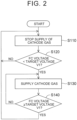
- FIG. 2 is a flowchart of cathode-gas intermittent supply control executed by the controller 20.
- the controller 20 starts the zero required output operating mode, it starts the cathode-gas intermittent supply control.
- the controller 20 finishes control of FIG. 2 , when it receives a command to stop operation in the zero required output operating mode, more specifically, when the ECU 21 requires the fuel cell stack 100 to generate electric power.
- the controller 20 stops supply of the anode gas, and places the shut valve 36 and the pressure regulating valve 37 in open states, while placing the bypass valve 38 in a closed state.
- the controller 20 When the cathode-gas intermittent supply control is started, the controller 20 initially stops supply of cathode gas (step S110). More specifically, the controller 20 sets the flow rate of cathode gas supplied from the compressor 34 to the fuel cell stack 100, to zero.
- the controller 20 determines whether the FC voltage is smaller than a target voltage V1 (step S120).
- the target voltage V1 is a voltage that can ensure sufficient output response, while curbing deterioration of the fuel cell stack 100, and is obtained in advance by experiment or simulation.
- the controller 20 stores the target voltage V1 in advance.
- the FC voltage is detected by the voltage detector 91.
- step S120: NO When the controller 20 determines that the FC voltage is equal to or larger than the target voltage V1 (step S120: NO), the control returns to step S110.
- step S120: YES the controller 20 performs operation to supply cathode gas (step S130). More specifically, the controller 20 causes the compressor 34 to supply cathode gas to the fuel cell stack 100.
- supply period P1 the period over which the controller 20 causes the compressor 34 to supply cathode gas
- stop period P2 the period over which the controller 20 stops supply of cathode gas
- the flow rate of air fed by the compressor 34 in the supply period P1 is smaller than the flow rate of air when the fuel cell stack 100 is required to generate electric power. As a result, the FC voltage can be made less likely to rise rapidly.
- the flow rate of air can be measured by the air flow meter 32.
- the flow rate of air fed by the compressor 34 in the supply period P1 is equal to or larger than 0.5 NL/min., and equal to or smaller than 30NL/min.
- the flow rate is equal to or larger than 3 NL/min., and is equal to or smaller than 14 NL/min.
- the flow rate of air when the fuel cell stack 100 is required to generate electric power is equal to or larger than 150 NL/min., and is equal to or smaller than 5000 NL/min.
- 1 NL/min. means that air flows in an amount of 1 L per minute, under base conditions (pressure: 0.1013 MPa, temperature: 0°C, humidity: 0%).
- the flow rate of air fed by the compressor 34 in the supply period P1 is equal to or smaller than 1% of the maximum flow rate of air when the fuel cell stack 100 is required to generate electric power.
- the FC voltage can be effectively made less likely to rise rapidly, and therefore, the durability of the fuel cell stack 100 is improved.
- step S140 After supply of cathode gas is started (step S130), the controller 20 determines whether the FC voltage is equal to or larger than the target voltage V1 (step S140). When the controller 20 determines that the FC voltage is smaller than the target voltage V1 (step S140: NO), the controller 20 continues supply of cathode gas (step S130). On the other hand, when the controller 20 determines that the FC voltage is equal to or larger than the target voltage V1 (step S140: YES), the control returns to step S110, and the controller 20 stops supply of cathode gas. The controller 20 repeats the above-described series of steps, until the zero required output operating mode ends.
- the timing chart of FIG. 3 represents the cathode-gas intermittent supply control.
- the horizontal axis indicates time, and the vertical axis indicates change of the FC voltage in the upper section, and the driving status of the compressor 34 in the lower section.
- a period of a part of the cathode-gas intermittent supply control is indicated.
- the controller 20 stops supply of cathode gas to the fuel cell stack 100. Namely, the controller 20 stops the compressor 34.
- the controller 20 supplies cathode gas to the fuel cell stack 100. Namely, the controller 20 drives the compressor 34.
- the period from time t1 to time t2 is the supply period P1 in which the compressor 34 is driven.
- the controller 20 stops supply of cathode gas to the fuel cell stack 100.
- the period from time t2 to time t3 is the stop period P2 in which the compressor 34 is stopped.
- a period from time t3 to time t4 is the supply period P1 in which the compressor 34 is driven
- a period from time t4 to time t5 is the stop period P2 in which the compressor 34 is stopped.
- one cycle including one supply period P1 and one stop period P2 is equal to or longer than two seconds, and is equal to or shorter than five seconds.
- the controller 20 controls the compressor 34 so that the supply period P1 and the stop period P2 appear alternately. Namely, the controller 20 alternately performs (or switches) supply and stop of cathode gas by the compressor 34. Also, as shown in FIG. 3 , the supply period P1 is longer than the stop period P2. Before the fuel cell system 10 is brought into the status shown in FIG. 3 , there may be a stop period P2 that is longer than the supply period P1. Namely, before the initial supply period P1 starts, there may be a stop period P2 that is longer than the supply period P1.
- the supply period P1 is longer than the stop period P2, and the flow rate of air fed by the compressor 34 in the supply period P1 is smaller than the flow rate of air when the fuel cell stack 100 is required to generate electric power.
- the rate of increase of the FC voltage that increases due to air fed by the compressor 34 can be reduced, so that the range of variation in the FC voltage can be reduced.
- a catalyst in the fuel cell stack 100 is less likely to deteriorate due to excessive increase of the FC voltage, and the fuel cell stack 100 can quickly respond to a request to generate electric power when there is any such request.
- the flow rate of air fed by the compressor 34 in the supply period P1 is smaller than the flow rate of air when the fuel cell stack 100 is required to generate electric power; therefore, the fuel efficiency can be improved, as compared with the case where these flow rates are made equal to each other.
- the supply period P1 is longer than the stop period P2. Therefore, the flowability of water vapor and water in the fuel cell stack 100 is improved, so that the environment within the fuel cell system 10 can be kept favorable.
- the controller 20 drives the compressor 34 when the voltage of the fuel cell stack 100 is smaller than the predetermined target voltage V1, and stops the compressor 34 when the voltage of the fuel cell stack 100 is larger than the target voltage V1. While the target voltage V1 used in step S120 and the target voltage V1 used in step S140 may be set to different values, control can be simplified if the target voltage V1 used in step S120 and the target voltage V1 used in step S140 are set to the same value, as in this embodiment.
- the turbo air compressor is used as the compressor 34.
- the power consumption at the start of operation is smaller, and the response is better, as compared with other types of air compressors.
- the supply period P1 and the stop period P2 can be quickly switched, and the power consumption can be reduced, resulting in improved fuel efficiency.
- the second embodiment is different from the first embodiment in that the controller 20 is configured to charge the secondary battery 92 with regenerative power generated when driving of the compressor 34 is stopped, at the time of switching from the supply period P1 to the stop period P2, but the first and second embodiments are identical with each other in other respects. According to the second embodiment, the secondary battery 92 is charged with regenerative power, so that the fuel efficiency can be improved.
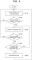
- FIG. 4 is a flowchart of cathode-gas intermittent supply control according to a third embodiment.
- the third embodiment is different from the first embodiment in step S150 and step S160, but is identical with the first embodiment in other respects.
- the controller 20 determines whether the FC voltage is smaller than a lower-limit voltage V2 (step S150).
- the lower-limit voltage V2 is a voltage at which the catalyst included in the fuel cell stack 100 switches between oxidation reaction and reduction reaction, for example, and is obtained in advance by experiment or simulation.
- the controller 20 stores the lower-limit voltage V2 in advance.
- the lower-limit voltage V2 is smaller than the target voltage V1.
- step S150 NO
- step S150: NO the controller 20 continues supply of cathode gas
- step S150: YES the controller 20 performs a purge process
- step S160 the control returns to step S110.
- the purge process is performed so as to reduce water that exists in the cathode gas passage 60 within the fuel cell stack 100.
- the air is supplied from the compressor 34 to the fuel cell stack 100, at a flow rate that is 10 times as large as the flow rate of air fed by the compressor 34 in the supply period P1.
- the purge process is performed for several seconds.
- the purge process makes it possible to recover the FC voltage reduced due to water that exists in the cathode gas passage 60 within the fuel cell stack 100.
Landscapes
- Life Sciences & Earth Sciences (AREA)
- Engineering & Computer Science (AREA)
- Sustainable Development (AREA)
- Sustainable Energy (AREA)
- Chemical & Material Sciences (AREA)
- Chemical Kinetics & Catalysis (AREA)
- Electrochemistry (AREA)
- General Chemical & Material Sciences (AREA)
- Manufacturing & Machinery (AREA)
- Fuel Cell (AREA)
Claims (4)
- Brennstoffzellensystem, umfassend:einen Brennstoffzellenstapel (100);einen Kompressor (34), der so konfiguriert ist, dass er dem Brennstoffzellenstapel (100) Kathodengas zuführt;eine Steuervorrichtung (20), die so konfiguriert ist, dass sie die Bestandteile des Brennstoffzellensystems einschließlich des Kompressors (34) steuert; undeinen Spannungsdetektor (91), der so konfiguriert ist, dass er eine Spannung des Brennstoffzellenstapels (100) erfasst;wobei:die Steuervorrichtung (20) so konfiguriert ist, dass sie, wenn der Brennstoffzellenstapel (100) keine elektrische Energie erzeugen muss, den Kompressor (34) abwechselnd so steuert, dass er das Kathodengas für eine Zufuhrperiode zuführt und die Zufuhr des Kathodengases für eine Stoppperiode stoppt, unddie Steuervorrichtung (20) so konfiguriert ist, dass sie den Kompressor (34) so steuert, dass er das Kathodengas zuführt, wenn die Spannung des Brennstoffzellenstapels (100) niedriger als eine vorbestimmte Spannung ist, und die Zufuhr des Kathodengases stoppt, wenn die Spannung des Brennstoffzellenstapels (100) größer als die vorbestimmte Spannung ist, wobei die Zufuhrperiode länger als die Stoppperiode ist und eine Strömungsrate des Kathodengases, das durch den Kompressor (34) in der Zufuhrperiode zugeführt wird, niedriger als eine Strömungsrate in einem Fall ist, in dem der Brennstoffzellenstapel (100) elektrische Energie erzeugen muss.
- Brennstoffzellensystem nach Anspruch 1, ferner umfassend:eine Sekundärbatterie (92),wobei die Steuervorrichtung (20) so konfiguriert ist, dass sie die Sekundärbatterie (92) mit regenerativer Energie auflädt, die erzeugt wird, wenn der Antrieb des Kompressors (34) gestoppt wird, und zwar zu einem Zeitpunkt des Umschaltens von der Zufuhrperiode zur Stoppperiode.
- Brennstoffzellensystem nach Anspruch 1 oder 2, wobei der Kompressor (34) einen Turboluftkompressor umfasst.
- Verfahren zum Steuern eines Brennstoffzellensystems, umfassend einen Brennstoffzellenstapel (100), einen Kompressor (34), der dem Brennstoffzellenstapel (100) Kathodengas zuführt, und einen Spannungsdetektor (91), der eine Spannung des Brennstoffzellenstapels (100) erfasst, wobei das Verfahren Folgendes umfasst:Steuern des Kompressors (34), wenn der Brennstoffzellenstapel (100) keine elektrische Energie erzeugen muss, so dass er das Kathodengas abwechselnd in einer Zufuhrperiode zuführt und die Zufuhr des Kathodengases in einer Stoppperiode stoppt, undSteuern des Kompressors (34) so, dass er das Kathodengas zuführt, wenn die Spannung des Brennstoffzellenstapels (100) niedriger als eine vorbestimmte Spannung ist, und die Zufuhr des Kathodengases stoppt, wenn die Spannung des Brennstoffzellenstapels (100) größer als die vorbestimmte Spannung ist, wobei die Zufuhrperiode länger als die Stoppperiode ist und eine Strömungsrate des durch den Kompressor (34) in der Zufuhrperiode zugeführten Kathodengases niedriger als eine Strömungsrate in einem Fall ist, in dem der Brennstoffzellenstapel (100) elektrische Energie erzeugen muss.
Applications Claiming Priority (1)
| Application Number | Priority Date | Filing Date | Title |
|---|---|---|---|
| JP2017216002A JP6992420B2 (ja) | 2017-11-09 | 2017-11-09 | 燃料電池システム及びその制御方法 |
Publications (2)
| Publication Number | Publication Date |
|---|---|
| EP3483969A1 EP3483969A1 (de) | 2019-05-15 |
| EP3483969B1 true EP3483969B1 (de) | 2025-03-26 |
Family
ID=63713723
Family Applications (1)
| Application Number | Title | Priority Date | Filing Date |
|---|---|---|---|
| EP18197735.6A Active EP3483969B1 (de) | 2017-11-09 | 2018-09-28 | Brennstoffzellensystem und verfahren zur steuerung dieses systems |
Country Status (6)
| Country | Link |
|---|---|
| US (1) | US10693160B2 (de) |
| EP (1) | EP3483969B1 (de) |
| JP (1) | JP6992420B2 (de) |
| KR (1) | KR102140528B1 (de) |
| CN (1) | CN109768305B (de) |
| RU (1) | RU2692475C1 (de) |
Families Citing this family (4)
| Publication number | Priority date | Publication date | Assignee | Title |
|---|---|---|---|---|
| JP7219170B2 (ja) * | 2019-06-12 | 2023-02-07 | 株式会社Soken | 燃料電池システム |
| JP7160025B2 (ja) * | 2019-12-23 | 2022-10-25 | トヨタ自動車株式会社 | 燃料電池システム |
| JP7294238B2 (ja) | 2020-05-26 | 2023-06-20 | トヨタ自動車株式会社 | 燃料電池システム |
| AT523992B1 (de) * | 2020-07-05 | 2022-06-15 | Avl List Gmbh | Verfahren zur Regelung einer Feuchtigkeit eines PEM-Brennstoffzellensystems eines Kraftfahrzeuges |
Family Cites Families (21)
| Publication number | Priority date | Publication date | Assignee | Title |
|---|---|---|---|---|
| JP4182732B2 (ja) * | 2002-11-22 | 2008-11-19 | トヨタ自動車株式会社 | 燃料電池システム、およびこれを搭載した移動体、および燃料電池システムの制御方法 |
| JP2005116402A (ja) | 2003-10-09 | 2005-04-28 | Nissan Motor Co Ltd | 燃料電池システムの起動方法 |
| JP4645937B2 (ja) | 2004-05-12 | 2011-03-09 | トヨタ自動車株式会社 | 燃料電池システム |
| JP4953151B2 (ja) * | 2005-01-11 | 2012-06-13 | トヨタ自動車株式会社 | 燃料電池システム |
| JP4432958B2 (ja) * | 2006-11-10 | 2010-03-17 | トヨタ自動車株式会社 | 燃料電池を搭載した移動体 |
| DE102007037096A1 (de) * | 2007-08-07 | 2009-02-12 | Daimler Ag | Verfahren und Vorrichtung zum Betreiben eines Brennstoffzellensystems mit einem in einen Brennstoffkreislauf des Brennstoffzellensystems angeordneten Rezirkulationsgebläse |
| US9005785B2 (en) * | 2007-09-24 | 2015-04-14 | GM Global Technology Operations LLC | Open-loop system and method for fuel cell stack start-up with low-voltage source |
| JP5381427B2 (ja) | 2009-07-07 | 2014-01-08 | トヨタ自動車株式会社 | 燃料電池システム |
| JP5545378B2 (ja) * | 2011-02-16 | 2014-07-09 | トヨタ自動車株式会社 | 燃料電池システムとこれを搭載した車両 |
| US9543603B2 (en) * | 2011-11-10 | 2017-01-10 | Nissan Motor Co., Ltd. | Fuel cell system and control method for fuel cell system |
| JP5811791B2 (ja) | 2011-11-10 | 2015-11-11 | 日産自動車株式会社 | 燃料電池システム |
| JP5811790B2 (ja) | 2011-11-10 | 2015-11-11 | 日産自動車株式会社 | 燃料電池システム |
| JP5508382B2 (ja) | 2011-12-28 | 2014-05-28 | 日産自動車株式会社 | 燃料電池システム |
| JP2012134166A (ja) | 2012-02-17 | 2012-07-12 | Nissan Motor Co Ltd | 燃料電池システム |
| JP5783324B2 (ja) | 2012-04-06 | 2015-09-24 | トヨタ自動車株式会社 | 燃料電池システム |
| EP3026743B1 (de) * | 2013-07-22 | 2018-02-21 | Nissan Motor Co., Ltd | Brennstoffzellenherstellungsverfahren und brennstoffzelle |
| JP6102882B2 (ja) * | 2014-10-16 | 2017-03-29 | トヨタ自動車株式会社 | 燃料電池システム |
| JP6206375B2 (ja) | 2014-11-12 | 2017-10-04 | トヨタ自動車株式会社 | 燃料電池システムおよび燃料電池搭載車両 |
| JP6237583B2 (ja) * | 2014-11-14 | 2017-11-29 | トヨタ自動車株式会社 | 燃料電池システムおよびエアコンプレッサの回転数制御方法 |
| JP6507667B2 (ja) | 2015-01-23 | 2019-05-08 | トヨタ自動車株式会社 | 燃料電池システム及び燃料電池システムの制御方法 |
| JP6607404B2 (ja) * | 2016-08-05 | 2019-11-20 | トヨタ自動車株式会社 | 燃料電池セルの発電検査方法 |
-
2017
- 2017-11-09 JP JP2017216002A patent/JP6992420B2/ja active Active
-
2018
- 2018-09-26 US US16/142,624 patent/US10693160B2/en active Active
- 2018-09-28 EP EP18197735.6A patent/EP3483969B1/de active Active
- 2018-10-04 RU RU2018134961A patent/RU2692475C1/ru active
- 2018-10-11 KR KR1020180120975A patent/KR102140528B1/ko active Active
- 2018-11-02 CN CN201811300561.8A patent/CN109768305B/zh active Active
Also Published As
| Publication number | Publication date |
|---|---|
| BR102018071878A2 (pt) | 2019-06-04 |
| JP2019087468A (ja) | 2019-06-06 |
| KR102140528B1 (ko) | 2020-08-03 |
| JP6992420B2 (ja) | 2022-02-04 |
| US10693160B2 (en) | 2020-06-23 |
| KR20190053087A (ko) | 2019-05-17 |
| EP3483969A1 (de) | 2019-05-15 |
| CN109768305A (zh) | 2019-05-17 |
| US20190140294A1 (en) | 2019-05-09 |
| CN109768305B (zh) | 2022-08-09 |
| RU2692475C1 (ru) | 2019-06-25 |
Similar Documents
| Publication | Publication Date | Title |
|---|---|---|
| KR101000703B1 (ko) | 연료전지 하이브리드 차량의 아이들 스탑/해제 제어 방법 | |
| CN102800884B (zh) | 燃料电池系统及其控制方法 | |
| US8084151B2 (en) | Fuel cell system and method therefor | |
| CN104205454B (zh) | 燃料电池系统 | |
| CN107123821B (zh) | 压力传感器的异常检测方法及燃料电池系统 | |
| CN109768303B (zh) | 燃料电池系统和控制燃料电池系统的方法 | |
| CN101569044A (zh) | 燃料电池系统 | |
| US20160141674A1 (en) | Fuel cell system and method of recoverying cell voltage thereof | |
| KR20120062932A (ko) | 연료전지 시스템, 연료전지 시스템의 정지 방법 | |
| US8288047B2 (en) | Fuel cell system with idle stop unit and current discharger | |
| KR20160056791A (ko) | 연료 전지 시스템, 및 연료 전지 시스템의 제어 방법 | |
| US20120107709A1 (en) | Fuel cell system and control method thereof | |
| US10693160B2 (en) | Fuel cell system and method of controlling the same | |
| KR20140144728A (ko) | 연료전지 시스템 | |
| WO2008023521A1 (en) | Fuel cell system and moving body | |
| US20180375120A1 (en) | Fuel cell system and control method for fuel cell system | |
| JP2006294554A (ja) | 燃料電池システムとその運転方法、及び燃料電池車両 | |
| CN104025372A (zh) | 控制混合系统操作的方法 | |
| JP5282881B2 (ja) | 燃料電池システム | |
| US7776481B2 (en) | Fuel cell system and method of controlling electrical energy discharged in the fuel cell system | |
| CN105609830B (zh) | 燃料电池系统及其控制方法 | |
| WO2008059902A1 (en) | Fuel cell system, method for controlling the fuel cell system, and mobile object | |
| CN101933188B (zh) | 燃料电池系统及其控制方法 | |
| US20120225365A1 (en) | Method for controlling fuel cell system | |
| JP6167864B2 (ja) | 燃料電池システムおよび燃料電池車両、燃料電池システムの制御方法 |
Legal Events
| Date | Code | Title | Description |
|---|---|---|---|
| PUAI | Public reference made under article 153(3) epc to a published international application that has entered the european phase |
Free format text: ORIGINAL CODE: 0009012 |
|
| STAA | Information on the status of an ep patent application or granted ep patent |
Free format text: STATUS: REQUEST FOR EXAMINATION WAS MADE |
|
| 17P | Request for examination filed |
Effective date: 20180928 |
|
| AK | Designated contracting states |
Kind code of ref document: A1 Designated state(s): AL AT BE BG CH CY CZ DE DK EE ES FI FR GB GR HR HU IE IS IT LI LT LU LV MC MK MT NL NO PL PT RO RS SE SI SK SM TR |
|
| AX | Request for extension of the european patent |
Extension state: BA ME |
|
| GRAP | Despatch of communication of intention to grant a patent |
Free format text: ORIGINAL CODE: EPIDOSNIGR1 |
|
| STAA | Information on the status of an ep patent application or granted ep patent |
Free format text: STATUS: GRANT OF PATENT IS INTENDED |
|
| INTG | Intention to grant announced |
Effective date: 20250113 |
|
| GRAS | Grant fee paid |
Free format text: ORIGINAL CODE: EPIDOSNIGR3 |
|
| GRAA | (expected) grant |
Free format text: ORIGINAL CODE: 0009210 |
|
| STAA | Information on the status of an ep patent application or granted ep patent |
Free format text: STATUS: THE PATENT HAS BEEN GRANTED |
|
| AK | Designated contracting states |
Kind code of ref document: B1 Designated state(s): AL AT BE BG CH CY CZ DE DK EE ES FI FR GB GR HR HU IE IS IT LI LT LU LV MC MK MT NL NO PL PT RO RS SE SI SK SM TR |
|
| REG | Reference to a national code |
Ref country code: GB Ref legal event code: FG4D |
|
| REG | Reference to a national code |
Ref country code: CH Ref legal event code: EP |
|
| REG | Reference to a national code |
Ref country code: DE Ref legal event code: R096 Ref document number: 602018080416 Country of ref document: DE |
|
| REG | Reference to a national code |
Ref country code: IE Ref legal event code: FG4D |
|
| PG25 | Lapsed in a contracting state [announced via postgrant information from national office to epo] |
Ref country code: RS Free format text: LAPSE BECAUSE OF FAILURE TO SUBMIT A TRANSLATION OF THE DESCRIPTION OR TO PAY THE FEE WITHIN THE PRESCRIBED TIME-LIMIT Effective date: 20250626 |
|
| PG25 | Lapsed in a contracting state [announced via postgrant information from national office to epo] |
Ref country code: FI Free format text: LAPSE BECAUSE OF FAILURE TO SUBMIT A TRANSLATION OF THE DESCRIPTION OR TO PAY THE FEE WITHIN THE PRESCRIBED TIME-LIMIT Effective date: 20250326 |
|
| REG | Reference to a national code |
Ref country code: LT Ref legal event code: MG9D |
|
| PG25 | Lapsed in a contracting state [announced via postgrant information from national office to epo] |
Ref country code: NO Free format text: LAPSE BECAUSE OF FAILURE TO SUBMIT A TRANSLATION OF THE DESCRIPTION OR TO PAY THE FEE WITHIN THE PRESCRIBED TIME-LIMIT Effective date: 20250626 |
|
| PG25 | Lapsed in a contracting state [announced via postgrant information from national office to epo] |
Ref country code: HR Free format text: LAPSE BECAUSE OF FAILURE TO SUBMIT A TRANSLATION OF THE DESCRIPTION OR TO PAY THE FEE WITHIN THE PRESCRIBED TIME-LIMIT Effective date: 20250326 |
|
| PG25 | Lapsed in a contracting state [announced via postgrant information from national office to epo] |
Ref country code: LV Free format text: LAPSE BECAUSE OF FAILURE TO SUBMIT A TRANSLATION OF THE DESCRIPTION OR TO PAY THE FEE WITHIN THE PRESCRIBED TIME-LIMIT Effective date: 20250326 |
|
| PG25 | Lapsed in a contracting state [announced via postgrant information from national office to epo] |
Ref country code: GR Free format text: LAPSE BECAUSE OF FAILURE TO SUBMIT A TRANSLATION OF THE DESCRIPTION OR TO PAY THE FEE WITHIN THE PRESCRIBED TIME-LIMIT Effective date: 20250627 Ref country code: BG Free format text: LAPSE BECAUSE OF FAILURE TO SUBMIT A TRANSLATION OF THE DESCRIPTION OR TO PAY THE FEE WITHIN THE PRESCRIBED TIME-LIMIT Effective date: 20250326 |
|
| REG | Reference to a national code |
Ref country code: NL Ref legal event code: MP Effective date: 20250326 |
|
| PG25 | Lapsed in a contracting state [announced via postgrant information from national office to epo] |
Ref country code: NL Free format text: LAPSE BECAUSE OF FAILURE TO SUBMIT A TRANSLATION OF THE DESCRIPTION OR TO PAY THE FEE WITHIN THE PRESCRIBED TIME-LIMIT Effective date: 20250326 |
|
| PG25 | Lapsed in a contracting state [announced via postgrant information from national office to epo] |
Ref country code: SE Free format text: LAPSE BECAUSE OF FAILURE TO SUBMIT A TRANSLATION OF THE DESCRIPTION OR TO PAY THE FEE WITHIN THE PRESCRIBED TIME-LIMIT Effective date: 20250326 |
|
| REG | Reference to a national code |
Ref country code: AT Ref legal event code: MK05 Ref document number: 1779867 Country of ref document: AT Kind code of ref document: T Effective date: 20250326 |
|
| REG | Reference to a national code |
Ref country code: DE Ref legal event code: R084 Ref document number: 602018080416 Country of ref document: DE |
|
| PG25 | Lapsed in a contracting state [announced via postgrant information from national office to epo] |
Ref country code: SM Free format text: LAPSE BECAUSE OF FAILURE TO SUBMIT A TRANSLATION OF THE DESCRIPTION OR TO PAY THE FEE WITHIN THE PRESCRIBED TIME-LIMIT Effective date: 20250326 |
|
| PG25 | Lapsed in a contracting state [announced via postgrant information from national office to epo] |
Ref country code: PT Free format text: LAPSE BECAUSE OF FAILURE TO SUBMIT A TRANSLATION OF THE DESCRIPTION OR TO PAY THE FEE WITHIN THE PRESCRIBED TIME-LIMIT Effective date: 20250728 Ref country code: ES Free format text: LAPSE BECAUSE OF FAILURE TO SUBMIT A TRANSLATION OF THE DESCRIPTION OR TO PAY THE FEE WITHIN THE PRESCRIBED TIME-LIMIT Effective date: 20250326 |
|
| PGFP | Annual fee paid to national office [announced via postgrant information from national office to epo] |
Ref country code: DE Payment date: 20250805 Year of fee payment: 8 |
|
| PG25 | Lapsed in a contracting state [announced via postgrant information from national office to epo] |
Ref country code: PL Free format text: LAPSE BECAUSE OF FAILURE TO SUBMIT A TRANSLATION OF THE DESCRIPTION OR TO PAY THE FEE WITHIN THE PRESCRIBED TIME-LIMIT Effective date: 20250326 Ref country code: IT Free format text: LAPSE BECAUSE OF FAILURE TO SUBMIT A TRANSLATION OF THE DESCRIPTION OR TO PAY THE FEE WITHIN THE PRESCRIBED TIME-LIMIT Effective date: 20250326 |
|
| PGFP | Annual fee paid to national office [announced via postgrant information from national office to epo] |
Ref country code: GB Payment date: 20250807 Year of fee payment: 8 |
|
| PG25 | Lapsed in a contracting state [announced via postgrant information from national office to epo] |
Ref country code: AT Free format text: LAPSE BECAUSE OF FAILURE TO SUBMIT A TRANSLATION OF THE DESCRIPTION OR TO PAY THE FEE WITHIN THE PRESCRIBED TIME-LIMIT Effective date: 20250326 |
|
| PGFP | Annual fee paid to national office [announced via postgrant information from national office to epo] |
Ref country code: FR Payment date: 20250808 Year of fee payment: 8 |
|
| PG25 | Lapsed in a contracting state [announced via postgrant information from national office to epo] |
Ref country code: EE Free format text: LAPSE BECAUSE OF FAILURE TO SUBMIT A TRANSLATION OF THE DESCRIPTION OR TO PAY THE FEE WITHIN THE PRESCRIBED TIME-LIMIT Effective date: 20250326 |
|
| PG25 | Lapsed in a contracting state [announced via postgrant information from national office to epo] |
Ref country code: RO Free format text: LAPSE BECAUSE OF FAILURE TO SUBMIT A TRANSLATION OF THE DESCRIPTION OR TO PAY THE FEE WITHIN THE PRESCRIBED TIME-LIMIT Effective date: 20250326 |
|
| PG25 | Lapsed in a contracting state [announced via postgrant information from national office to epo] |
Ref country code: SK Free format text: LAPSE BECAUSE OF FAILURE TO SUBMIT A TRANSLATION OF THE DESCRIPTION OR TO PAY THE FEE WITHIN THE PRESCRIBED TIME-LIMIT Effective date: 20250326 |
|
| PG25 | Lapsed in a contracting state [announced via postgrant information from national office to epo] |
Ref country code: IS Free format text: LAPSE BECAUSE OF FAILURE TO SUBMIT A TRANSLATION OF THE DESCRIPTION OR TO PAY THE FEE WITHIN THE PRESCRIBED TIME-LIMIT Effective date: 20250726 |
|
| REG | Reference to a national code |
Ref country code: DE Ref legal event code: R097 Ref document number: 602018080416 Country of ref document: DE |
|
| PG25 | Lapsed in a contracting state [announced via postgrant information from national office to epo] |
Ref country code: DK Free format text: LAPSE BECAUSE OF FAILURE TO SUBMIT A TRANSLATION OF THE DESCRIPTION OR TO PAY THE FEE WITHIN THE PRESCRIBED TIME-LIMIT Effective date: 20250326 |
|
| PG25 | Lapsed in a contracting state [announced via postgrant information from national office to epo] |
Ref country code: CZ Free format text: LAPSE BECAUSE OF FAILURE TO SUBMIT A TRANSLATION OF THE DESCRIPTION OR TO PAY THE FEE WITHIN THE PRESCRIBED TIME-LIMIT Effective date: 20250326 |
|
| REG | Reference to a national code |
Ref country code: GB Ref legal event code: 746 Effective date: 20260112 |
|
| PLBE | No opposition filed within time limit |
Free format text: ORIGINAL CODE: 0009261 |
|
| STAA | Information on the status of an ep patent application or granted ep patent |
Free format text: STATUS: NO OPPOSITION FILED WITHIN TIME LIMIT |
|
| REG | Reference to a national code |
Ref country code: CH Ref legal event code: L10 Free format text: ST27 STATUS EVENT CODE: U-0-0-L10-L00 (AS PROVIDED BY THE NATIONAL OFFICE) Effective date: 20260211 |
|
| 26N | No opposition filed |
Effective date: 20260105 |
|
| REG | Reference to a national code |
Ref country code: CH Ref legal event code: H13 Free format text: ST27 STATUS EVENT CODE: U-0-0-H10-H13 (AS PROVIDED BY THE NATIONAL OFFICE) Effective date: 20260504 |