EP3481979B1 - Einen zwischengarnpuffer formende schussfadenzuführvorrichtung und verfahren zur steuerung einer schussfadenzuführvorrichtung - Google Patents
Einen zwischengarnpuffer formende schussfadenzuführvorrichtung und verfahren zur steuerung einer schussfadenzuführvorrichtung Download PDFInfo
- Publication number
- EP3481979B1 EP3481979B1 EP17824624.5A EP17824624A EP3481979B1 EP 3481979 B1 EP3481979 B1 EP 3481979B1 EP 17824624 A EP17824624 A EP 17824624A EP 3481979 B1 EP3481979 B1 EP 3481979B1
- Authority
- EP
- European Patent Office
- Prior art keywords
- yarn
- feeding device
- weft yarn
- weaving machine
- weft
- Prior art date
- Legal status (The legal status is an assumption and is not a legal conclusion. Google has not performed a legal analysis and makes no representation as to the accuracy of the status listed.)
- Active
Links
Images



Classifications
-
- D—TEXTILES; PAPER
- D03—WEAVING
- D03D—WOVEN FABRICS; METHODS OF WEAVING; LOOMS
- D03D47/00—Looms in which bulk supply of weft does not pass through shed, e.g. shuttleless looms, gripper shuttle looms, dummy shuttle looms
- D03D47/34—Handling the weft between bulk storage and weft-inserting means
- D03D47/36—Measuring and cutting the weft
-
- D—TEXTILES; PAPER
- D03—WEAVING
- D03D—WOVEN FABRICS; METHODS OF WEAVING; LOOMS
- D03D47/00—Looms in which bulk supply of weft does not pass through shed, e.g. shuttleless looms, gripper shuttle looms, dummy shuttle looms
- D03D47/34—Handling the weft between bulk storage and weft-inserting means
-
- D—TEXTILES; PAPER
- D03—WEAVING
- D03D—WOVEN FABRICS; METHODS OF WEAVING; LOOMS
- D03D47/00—Looms in which bulk supply of weft does not pass through shed, e.g. shuttleless looms, gripper shuttle looms, dummy shuttle looms
- D03D47/34—Handling the weft between bulk storage and weft-inserting means
- D03D47/347—Yarn brakes
Definitions
- the present disclosure relates to a weft yarn feeding arrangement.
- the present disclosure relates to a weft yarn feeding arrangement suitable for a weaving machine operated at high speed and potentially also with yarns with relatively high weight per length unit.
- Weft yarn pre-winders are used to eliminate yarn tension variations to ensure high textile quality and productivity of a textile machine, e.g. a shuttleless weaving machine or knitting machine.
- a general development trend in weaving is that the speed of the weaving machine is constantly being increased. At the same time the weavers strive to weave coarser yarns and also weaker yarns. Coarser yarns and higher speeds lead to increased tension of the weft yarn. Using conventional weft yarn pre-winders, increased speeds as well as coarser yarns result in a bigger take off yarn balloon in the weft yarn pre-winder, which needs to be reduced using a high braking force but thereby unfortunately leading to an undesirably high output yarn tension.
- a brush ring is often worn out in as little as a day and a flexible truncated-cone brake element can be worn out in a few months.
- Another example is weaving technical fabric with coarse synthetic yarns; where one faces the same problem as in a carpet weaving machine.
- the insertion means in the rapier weaving machine consists of one or two rigid or flexible rapiers that mechanically transfers the weft yarn from one end of the shed of the machine to the other.
- the most common system is two rapiers which meet in the middle of the shed where the weft yarn tip is transferred from the first, giving, rapier to the second, receiving, rapier.
- the first rapier is first accelerating from zero to full speed and then decelerating to zero again at the tip transfer point. This type of motion is analogous for the second rapier. This leads to a weft yarn tension that goes from low to high and then back to low again.
- GB 1355687 describes a yarn feeder where a member directly connected to the weaving machine moves back and forth to remove yarn in unison with the movement of the rapier from a yarn package during both a forward and return movement of the rapier. Hereby, the speed at which the yarn is drawn from the yarn package can be reduced to one half.
- the arrangement in GB 1355687 thereby provides a yarn buffer that enables the machine to draw yarn with a lower force than if the yarn would by drawn directly from the yarn package.
- EP 0467059 A1 describes a weft yarn feeding device for feeding weft yarn to a rapier weaving machine, forming an intermediate yarn buffer between a weft yarn storage and the weaving machine, the weft yarn feeding device comprising a yarn guide provided on a moving member driven by a controlled motor comprised in the weft yarn feeding device to cause the moving member to move back and forth.
- the deflection of the moving element forming the intermediate yarn buffer is only used to maintain the tension of the inserted weft after weft insertion.
- the device described in GB 1355687 allows for a reduced speed at which the yarn is drawn from the yarn feeder, it has limitations and drawbacks.
- the speed reduction can only be 50% and not more.
- the fact that the member is directly connected to the weaving machine and moves back and forth to remove yarn in unison with the movement of the rapier from a yarn package during both a forward and return movement of the rapier makes it impossible to draw yarn from the yarn storage when the rapier is not moving such as during beat up.
- the device in accordance with GB 1355687 moves in unison with the rapiers as it is mechanically coupled to the drive of the rapiers in the weaving machine limits the functionality as it is not possible to improve the function by following another movement in order to even out the speed even more and/or compensate for other movements in the weaving machine.
- the device requires a traveler guided along a rail, which imposes additional friction forces, which could be a disadvantage in some applications.
- a weft yarn feeding device for feeding yarn to a weaving machine.
- the yarn feeding device forms an intermediate yarn buffer between a weft yarn storage and the weaving machine.
- weft yarn is inserted into the shed and the weaving machine is provided with at least one rapier.
- the weft yarn feeding device has at least one yarn guide provided on a moving member driven by a controlled motor comprised in the yarn feeding device to cause the moving member to move back and forth.
- yarn is drawn from a weft yarn storage via said at least one guide provided on said moving member to the weaving machine.
- the moving member can move back and forth along some path as determined by the drive of the controlled motor and the mechanism used to achieve the back and forth movement.
- a yarn buffer of variable size can be formed.
- the motor can be driven to increase the yarn buffer when the weft yarn insertion speed of a rapier is low and to release yarn from the yarn buffer when the yarn insertion speed of a rapier is high.
- yarn can be released when the yarn insertion speed of the rapier is above some preset threshold value and the yarn buffer can be increased when the yarn insertion speed of the rapier is below some preset threshold value or when the there is no yarn insertion.
- the yarn buffer will provide an arrangement that can hold a bit of yarn that can be drawn with a small force during at least a part of the weaving cycle compared to the force required if the yarn would have been drawn directly from the yarn storage. This will cause the maximum yarn take off speed from the weft yarn storage to be significantly reduced.
- the motor is adapted to be controlled using a model of a parameter related to a set of positions of the rapier(s) in the weaving machine.
- the motor can be driven to adjust the yarn buffer in a pattern mirroring/representing the movements in the weaving machine.
- the motor can be adapted to be controlled using a model of different angular positions in the weaving machine at particular points in the time of the weaving cycle.
- the motor can be driven to ultimately adjust the yarn buffer to draw yarn from the weft yarn storage at essentially constant speed.
- the motor can be adapted to move the moving member in a pattern to minimize the maximum speed of the yarn drawn from the weft yarn storage during a weaving cycle of the weaving machine. This can be achieved by controlling the yarn buffer such that the take of speed from the yarn storage is constant during an entire cycle of the weaving machine.
- the motor is adapted to move the moving member, with its yarn guide, in a pattern whereby the maximum speed of the yarn drawn from the weft yarn storage is less than 50% of the maximum speed of the rapier(s). This can be achieved by using the time when no yarn insertion takes place to increase the yarn buffer and by releasing yarn from the yarn buffer when the insertion speed of a rapier is higher than a preset insertion speed.
- the motor is adapted to move the moving member in a pattern to also compensate for yarn movement caused by at least one of the following events in the weaving machine: weft selector movement, beat up, yarn cutting, rapier start, weft yarn tip transfer and weft yarn arrival. This can be achieved by programming any such event into a model controlling the motor and by supplying the angular position of the weaving machine to the controller controlling the motor.
- the moving member is an arm.
- the arm can be directly mounted on the motor.
- the arm can be connected to the output shaft of the motor.
- the moving member is a member following a linear path.
- the moving member can be driven back and forth along the linear path.
- an alternative mechanism for providing the back and forth movement can be achieved.
- the weft yarn feeding device is adapted to draw the yarn from a weft yarn storage comprising a pre-winder.
- the weft yarn feeding device is adapted to draw yarn directly from a bobbin.
- the invention also extends to methods for controlling a weft yarn feeding device in accordance with the above and to a controller and computer program product for controlling the weft yarn feeding device in accordance with the above.
- the invention further extends to an arrangement comprising a weft yarn feeding device in accordance with the above.
- the arrangement can in some embodiments comprise a slip feed device for the weft yarn.
- a yarn feeding device comprising a controlled motor.
- the motor is a motor designated for the device and can be controlled independently of the movements of a weaving machine.
- the yarn feeding device comprises a yarn path deviating/yarn deflecting arm with a yarn guide, or a similar member, driven by the motor.
- the yarn feeding device forms an intermediate yarn buffer between the weft yarn storage and the weaving machine.
- the yarn feeding device is adapted to draw yarn directly from a bobbin.
- a pre-winder is provided after the bobbin and the device is adapted to draw yarn from the pre-winder.
- the weft yarn tension in to the yarn feeding device is lower and typically much more even than if the yarn feeding device would take yarn directly from the bobbin.
- the weft yarn tension in to the device is transferred, and potentially even amplified, via the yarn feeding device to the weaving machine.
- a pre-winder before the yarn feeding device ensures a lower and much more even yarn tension to the weaving machine which results in less stops and a better weaving process.
- the aim is to reduce and to even out the yarn take off speed, either from the bobbin or if a pre-winder is provided, from the pre-winder. By this step two things are achieved:
- the maximum yarn take off speed from the weft yarn storage is lower. This will for example reduce the wear of balloon braking elements if a pre-winder is used. As the speed is lower also the balloon will be smaller and the balloon braking elements can be set to a lower yarn tension, thereby reducing the wear even further.
- the reduced yarn take off speed will give a lower yarn tension which in turn gives a lower stress on the yarn and also a lower stress on the rapier insertion mechanism.
- the target is set to have approximately constant yarn take off speed from the yarn storage such as a pre-winder or directly from a bobbin. This means that the yarn that the rapier takes is coming both from the intermediate yarn buffer formed by the device and also at the same time from the weft yarn storage.
- the maximum yarn speed from the weft yarn storage can then typically be reduced with more than 50% or up to 70% or even more of the maximum speed of the rapier.
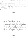
- Fig. 1 shows an exemplary embodiment of a weft yarn feeding device 16 forming a motor driven yarn buffer device between a weft yarn storage and a weaving machine 10.
- the weaving machine 10 is a double sided rapier weaving machine having two rapiers 11 and 12.
- the weft yarn storage comprises a pre-winder 14.
- the pre-winder 14 can in turn draw yarn 40 from a bobbin 13.
- the weft yarn feeding device 16 comprises a motor 18.
- the motor is a motor 18 designated for the yarn feeding device 16 and separate from any motor of the weaving machine 10.
- the motor 18 drives a moving member 19.
- the moving member 19 is an arm directly connected to the motor 18.
- the moving member can be directly connected to the output shaft 15 of the motor 18.
- the arm is not directly connected to the motor 18.
- the moving member can also be another type of element driven by the motor 18.
- the motor 18 is adapted to drive the moving member to a desired position based on an input signal. It is preferred that that the motor is a high performance electrical motor.
- the electrical motor should be fast enough to enable rapid movements required by the moving member 19.
- the moving member is driven back and forth along a linear path by the motor or a path with some pre-determined deviation from a linear path.
- the moving member 19 is provided with at least one guide 20 adapted to guide yarn 40 along a path formed by the position of the moving member 19.
- the guide 20 can be any suitable element which is able to form a yarn loop.
- the guide 20 can be an element on which the yarn 40 can slide or roll.
- the guide 20 will move between two different position, one first position where a maximum yarn buffer is formed and a second position where a minimum yarn buffer is formed.
- the first and second position can typically be the same for consecutive weaving cycles, but could in some embodiments differ from one weaving cycle to a following weaving cycle.
- the first and second positions will be determined by the control of the motor that can be based on the angular position of the weaving machine.
- the motor 18 can be driven in any suitable way to provide any desired movement of the moving member.
- a controller (see below) can be used to drive the separate motor 18 of the yarn feeding device to perform a movement pattern that does not exactly follow a pattern related to the actual motion of the rapier(s).
- the drive of the motor 18 is autonomous relative to the drive of the rapiers of the weaving machine.
- Fig. 1 an arrangement where guide elements 22, 24 are provided before and after the weft yarn feeding device 16 is shown.
- the length of the yarn buffer can differ based on the application at hand, but can typically be in the order of a few decimeters. For example, at least 10 cm or at least 20 cm of yarn. In some applications, the buffer can be larger such as at least 40 cm or at least 70 cm of yarn.
- Fig. 1 The configuration shown in Fig. 1 will add about 360° extra friction angles for the yarn 40. This will increase the yarn tension and potentially reduce the positive effect from the weft yarn feeding device 16. By providing the guide elements 22 and 24 spaced more apart, the added friction angles can be reduced.
- Fig. 2 which is similar to the arrangement of Fig. 1 , shows an embodiment with the guide elements 22 and 24 spaced more apart.
- the guide elements can in accordance with some embodiments be spaced apart with at least 25 cm or 50 cm.
- the guide elements 22, 24 can be spaced apart with at least 100 cm.
- a consequence of a set-up as shown in Fig. 2 is that the friction angles of the guide elements 22, 24 will vary with the position of the guide 20.
- one or both the guide elements are omitted. This will limit the friction angles and keep them constant.
- Fig. 3 an embodiment with no guide elements 22, 24 is shown. In the configuration of Fig. 3 the added friction angle is always around 180°, such as between 150° and 210°.
- the only yarn guide element of the moving member that the yarn passes from the yarn storage to the weaving machine is the guide 20. This is made possible by locating the yarn storage closer to the weaving machine than the weft yarn feeding device and arranging the yarn guide 20 move between two end positions, where the two end positions, the yarn output from the yarn storage, and the yarn input to the weaving machine are located essentially along one line. It also enables a layout that is more compact in a direction perpendicular to the insertion direction.
- Control of the moving member is primarily based on the rapier movement, with the target to have:
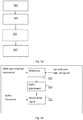
- FIG. 4 an exemplary set-up for a double sided rapier weaving machine is illustrated where the yarn speed at insertion is shown by the line 50. This speed is the result of the rapiers at different angular weaving cycle positions in the weaving machine.
- the movement of the moving member (and the yarn guide used to form a yarn loop) driven by the controlled motor is depicted by the line 60. As can be seen in Fig.
- the motor can be driven to release yarn from the yarn buffer formed by the yarn loop when the rapier is picking yarn at a high speed, in particular higher than the average yarn pick speed, and to fill the yarn buffer when the rapier is picking yarn at a low speed, in particular lower than the average yarn pick speed, and also during the part of the weaving machine cycle when none of the rapiers are engaged in picking yarn.
- yarn is taken from the weft yarn storage with relatively small variations in the take-of-speed.
- Such a control method can result in that the yarn take-off speed from the weft yarn storage will be essentially the same during the entire weaving cycle of the weaving machine as is depicted by line 70. As a result, the maximum yarn take-off speed can be significantly reduced.
- Fig. 4 The diagram of Fig. 4 is for illustration purpose only. The machine angles are approximate and serve(s) only as examples. The timing of the different actions in the weaving machine differs for different machine types.
- the reed is moving backwards and the shed is opening.
- the rapiers are not engaged in picking any yarn.
- the controlled motor 18 is programmed to drive the moving member 19 in a movement in order to increase the yarn buffer by pulling yarn from the yarn storage.
- the giving rapier takes the yarn and the insertion starts.
- the controlled motor 18 is programmed to drive the moving member 19 in a movement to increase the yarn buffer.
- the speed at which the moving member is driven is decreased, preferably gradually, as the rapier speed increases.
- both the moving member and the weaving machine takes yarn from the yarn storage.
- the combined speed of the rapier and the moving member result in a weft yarn take off speed from the yarn storage speed close to the average yarn speed.
- the moving member changes direction of its movement and now the moving member is driven to release yarn, by controlling the motor to drive the moving member in the other direction.
- the result of the moving member release speed and the rapier speed still gives a yarn storage speed in the same magnitude as the average yarn speed.
- the yarn feeding device releases yarn from the buffer.
- the weaving machine takes yarn both from the buffer and from the yarn storage.
- the rapier has reached its top speed.
- the moving member is at maximum negative speed and this is the point when most yarn is released from the buffer.
- the rapier decelerates and at 180 degrees the rapier speed is zero.
- the yarn feeding device still releases yarn from the buffer.
- the moving member is driven to change direction and the yarn buffer is increased.
- the yarn buffer increases.
- the moving member is controlled to be driven to build up the buffer to both counteract the tension drop and to increase the yarn in the buffer to have enough yarn for the receiving rapier cycle.
- the weaving machine takes yarn from the yarn storage.
- both the rapier and the moving member takes yarn from the yarn storage, thus increasing the yarn tension at the yarn tip, which is desired in order to ensure a safe yarn tip transfer function.
- the giving rapier transfers the yarn tip to the receiving rapier.
- the receiving rapier cycle takes place, and the movements of the rapier and moving member of the yarn feeding device is repeated in a similar or analogous way as for the giving rapier described above.
- the receiving rapier releases the yarn and the weft insertion is ready.
- the moving member is driven to increase the buffer, to increase the yarn tension before the end of insertion and to build up the buffer for next insertion.
- the beat up when the reed is pushing in the inserted weft thread into the woven fabric, takes place. During this period, the moving member is moved to increase the buffer to be ready for the next pick of the weaving machine.
- the aim during all or at least most of the above described different angular intervals of a weaving machine cycle is to achieve an even weft yarn take off speed from the yarn storage that is the same as the average weft yarn take off speed (with some pre-determined tolerance) or a weft yarn take off speed below a pre-determined maximum weft yarn take off speed.
- the motor is therefore controlled to be driven to adjust the buffer formed by the moving member to even out the take-off speed from the yarn storage.
- a single or double sided rapier weaving machine having one or two rapiers has been assumed.
- other types of weaving machines with more than one shed for example a carpet or velvet machine has typically two sheds, with two or more sets of rapiers that move in parallel from the same side.
- the here described weft yarn feeding device can then be implemented in such a way that one yarn loop forming moving member is designed to feed/supply yarn to more than one rapier in the same time.
- the moving member 19 can have two yarn guides 20 that are connected upstream with two weft yarn storages and downstream with two rapiers working in parallel to two different sheds in the same weaving machine.
- the weft yarn feeding device as described herein can be used in any type of rapier weaving machine.
- the weft yarn feeding arrangement will form a yarn buffer having variable length.
- a model of the movements of the weaving machine at different angular weaving cycle positions of the weaving machine is determined.
- the movement model can typically reflect the weft yarn movement or weft yarn tension variations at different angular weaving cycle positions of the weaving machine.
- a position signal indicative of the current angular weaving cycle position of the weaving machine is received.
- a model of different events in the weaving machine are determined.
- the events can for example be one or more of weft selector movement, beat up, yarn cutting, rapier start, yarn tip transfer and yarn arrival.
- the movement of the motor 18 and thereby the yarn buffer formed by the yarn feeding device comprising the motor and associated parts are controlled based on the model of the weaving machine at different angular weaving cycle positions.
- the control can in accordance with some embodiments also take into account different events in the weaving machine during each weaving cycle as will be described in more detail below.
- the model can also take into account the geometry of the yarn feeding device such that the model can translate a drive signal to the motor to a corresponding adjustment of the weft yarn buffer. In other words, by modelling how a particular drive signal will change the yarn buffer, the motor drive signal can be controlled to adapt the yarn buffer size to match the movements in the weaving machine to meet the ultimate aim of reducing the maximum weft yarn take off speed from the yarn storage.
- a control model illustrating the above is depicted.
- a difference between the weft yarn movement caused by the insertion into the weaving machine and the desired set weft yarn take off speed is determined.
- the difference value determined in step 521 is translated to a desired buffer adjustment illustrated in model step 523.
- a motor drive signal is output based on the geometry of the weft yarn buffer (or a model thereof) and the desired buffer adjustment. As a result, the motor will be driven to cause the buffer to be adjusted over time to keep the set weft yarn take off speed from the yarn storage at the set speed.
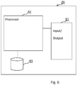
- a controller 26 for controlling a weft yarn feeding device is depicted.
- the controller 26 can comprise an input/output 81 for receiving input signals indicative of the angular weaving cycle position of the weaving machine and for outputting a motor control signal to the motor 18.
- the controller 26 further comprises a micro-processor that also can be referred to a processing unit 82.
- the processing unit 82 is connected to and can execute computer program instructions stored in a memory 83.
- the memory 83 can also store data that can be accessed by the processing unit 82.
- the data in the memory can in particular comprise a model of the movements of the weaving machine 10.
- the computer program instructions can be adapted to cause the controller to control the motor in accordance with the teachings herein.
- the controller can be located at any suitable location. For example, the controller can be integrated in the motor 18.
- the controller can input output data using any suitable means. Both wireless and wireline communication devices can be used.
- a light weight moving arm or other yarn loop forming member can be used. It can be of several types, for example using light and stiff materials like carbon fiber, or a light weight design in aluminum sheet.
- a moving member working partly counter to the rapier movement as described hereinabove will give further advantages.
- the rapier and thus the weft yarn is slowing down strongly twice in each insertion cycle.
- a controlled brake is often used.
- the brake force must be very high, which has negative effects on both the weft yarn and the weft insertion function, as well as the fact that a very large and energy consuming controlled brake is needed.
- the weft yarn feeding device as described herein will drive the moving member 19 in order to increase the yarn buffer.
- the weft yarn feeding device can be controlled to increase the weft yarn buffer at events when the yarn is to be stretched. This can for example be when a rapier is retarding.
- Another event is at beat up and cutting of the weft yarn, where often a surplus of weft yarn between the pre-winder and weaving machine is created due to the geometry and movement of the shed/slay and other parts involved in the weft insertion.
- Today a spring loaded take up device is often used, but has some disadvantages.
- One disadvantage is that the spring loaded system is sometimes to slow to follow the yarn slack that is created.
- Another disadvantage is that the yarn force is used to overcome the spring force and move the take up device, thus creating additional yarn tension. That problem can be avoided with a weft yarn feeding device as described herein.
- the here described weft yarn feeding device can be controlled to compensate for the drop in yarn tension by moving the member 19 to stretch the yarn. Similarly, before a yarn tension peak is reached the member 19 can be moved to decrease the yarn tension.
- a slip feed device is added.
- the slip feed device is a driven roller that rotates with a peripheral speed that is higher than the necessary yarn speed.
- a driven roller that rotates with a peripheral speed that is higher than the necessary yarn speed.
- Using a slip feed device in the weft yarn feeding device as described herein can lower the yarn tension in to the weaving machine.
- the disadvantage of the added friction angles can be reduced, and even turned into a yet better system.
- the system can be optimized for low yarn tension, or the combination can be used to build a compact system that fits to the available space at the weaving machine.
- a weft yarn feeding device comprising a motor driven yarn buffer combined with a slip feed roller after the yarn buffer is shown.
- the yarn tension of the yarn fed to the buffer will be lower.
- the load on the yarn buffer will be lower enabling a lower strength and thus weight of the moving arm (when an arm is used) in the weft yarn feeding device. Both the lower yarn tension on the moving arm and the lower weight will reduce the load on the motor that drives the arm.
- Fig 9 Such a configuration is shown in Fig 9 .
- a slip feed device can also be provided both before and after the yarn buffer.
- the same slip feed device is used both before and after the yarn buffer.
- a configuration using the same slip feed device both before and after the yarn buffer is shown in Fig. 10 .
- the slip feed device 28 can be designed in many different ways.
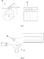
- One design is shown in Fig. 11 .
- the design in Fig. 11 comprises two rolls 29, 30. The rolls are arranged following each other along the path of the yarn.
- the rolls 29, 30 can be controlled to move in relation to each other.
- the motor driven moving element can have different configurations.
- the number of guides on the moving element can be more than one.
- One alternative configuration is shown in Fig. 12 .
- a weft yarn feeding device 16 has an arm provided with two yarn guides 20.
- the guides 20 can then be formed by a pair of elements each.
- one guide is located at each end of an arm forming the moving element.
- the arm can be driven to rotate back and forth to adjust the yarn buffer of the yarn feeding device.
- the motor used can be any suitable motor that can be controlled to drive a moving member in accordance with the above.
Landscapes
- Engineering & Computer Science (AREA)
- Textile Engineering (AREA)
- Looms (AREA)
Claims (15)
- Schussfadenzuführvorrichtung (16) zum Zuführen von Schussfaden (40) zu einer Webmaschine (10), wobei die Fadenzuführvorrichtung einen Fadenzwischenpuffer zwischen einem Schussfadenspeicher und der Webmaschine (10) bildet, wobei der Faden in das Webfach der Webmaschine eingelegt wird, das mindestens einen Greifer (11, 12) aufweist, wobei die Schussfadenzuführvorrichtung mindestens eine Fadenführung (20) umfasst, die auf einem beweglichen Element (19) bereitgestellt ist, das von einem gesteuerten Motor (18) angetrieben wird, der in der Schussfadenzuführvorrichtung umfasst ist, um zu bewirken, dass sich das bewegliche Element vor und zurück bewegt, dadurch gekennzeichnet, dass die Schussfadenzuführvorrichtung (16) konfiguriert ist, um Faden von einem Schussfadenspeicher (13, 14) über die mindestens eine Führung (20), die auf dem beweglichen Element (19) bereitgestellt ist, zu der Webmaschine (10) zu ziehen.
- Fadenzuführvorrichtung (16) nach Anspruch 1, wobei der gesteuerte Motor (18) ausgelegt ist, um unter Verwendung eines Modells eines Parameters oder eines Satzes von Parametern gesteuert zu werden, die sich auf einen Satz von Positionen des Greifers (der Greifer) in der Webmaschine (10) bei unterschiedlichen Webzyklus-Winkelpositionen in der Webmaschine an entsprechenden bestimmten Punkten in der Zeit des Webzyklus beziehen.
- Fadenzuführvorrichtung (16) nach Anspruch 1 oder 2, wobei sich der Fadenspeicher (13, 14) näher an der Webmaschine (10) befindet ist als die Schussfadenzuführvorrichtung und wobei die Fadenführung (20) angeordnet ist, um sich zwischen zwei Endpositionen zu bewegen, wobei sich die beiden Endpositionen, ein Fadenausgang aus dem Fadenspeicher und ein Fadeneingang in die Webmaschine im Wesentlichen entlang einer Linie befinden.
- Fadenzuführvorrichtung (16) nach einem der Ansprüche 1 - 3, wobei der gesteuerte Motor (18) ausgelegt ist, um das bewegliche Element (19) auf der Grundlage der Greiferbewegung(en) in einem Muster zu bewegen, das die Schussfaden-Abzugsgeschwindigkeit aus dem Schussfadenspeicher innerhalb eines Zielbereichs hält oder das während eines Webzyklus der Webmaschine konstant ist.
- Fadenzuführvorrichtung (16) nach Anspruch 4, wobei der gesteuerte Motor (18) ausgelegt ist, um das bewegliche Element (19) in einem Muster zu bewegen, wobei die maximale Geschwindigkeit des Fadens, der aus dem Schussfadenspeicher (13, 14) gezogen wird, weniger als 50% der maximalen Geschwindigkeit des Greifers (der Greifer) beträgt.
- Fadenzuführvorrichtung (16) nach einem der Ansprüche 1 - 5, wobei der gesteuerte Motor (18) ausgelegt ist, um das bewegliche Element (19) in einem Muster zu bewegen, um auch die Fadenbewegung zu kompensieren, die durch mindestens eines der folgenden Ereignisse in der Webmaschine bewirkt wird: Bewegung des Schussfadenwählers, Anschlag, Fadenschneiden, Greiferstart, Übergabe der Schussfadenspitze und Ankunft des Schussfadens.
- Fadenzuführvorrichtung (16) nach einem der Ansprüche 1 - 6, wobei das bewegliche Element (19) ein Arm ist.
- Fadenzuführvorrichtung (16) nach Anspruch 7, wobei der Arm direkt auf der Abtriebswelle des Motors (18) montiert ist.
- Fadenzuführvorrichtung (16) nach einem der Ansprüche 1 - 6, wobei das bewegliche Element (19) ein Element ist, das einem linearen Weg folgt.
- Fadenzuführvorrichtung (16) nach einem der Ansprüche 1 - 9, wobei die Schussfadenzuführvorrichtung ausgelegt ist, um den Faden aus einem Schussfadenspeicher zu ziehen, der einen Fadenvorwickler (14) umfasst.
- Fadenzuführvorrichtung (16) nach einem der Ansprüche 1 - 9, wobei der Schussfadenspeicher eine Spule (13) ist und die Schussfadenzuführvorrichtung ausgelegt ist, um Faden (40) direkt von der Spule zu ziehen.
- Schussfadenzuführanordnung, umfassend einen Schussfadenspeicher (13, 14), eine Schussfadenzuführvorrichtung (16) nach einem der Ansprüche 1 - 11, eine Webmaschine (10) und eine Schlupfzuführvorrichtung (28), die zwischen der Schussfadenzuführvorrichtung und der Webmaschine zwischengeschaltet ist.
- Fadenzuführanordnung nach Anspruch 12, wobei die Schlupfzuführvorrichtung (28) zwischen dem Schussfadenspeicher (13, 14) und der Schussfadenzuführvorrichtung (16) zwischen geschaltet ist.
- Verfahren zum Steuern einer Schussfadenzuführvorrichtung (16), die einer Webmaschine (10) Faden (40) zuführt, wobei die Fadenzuführvorrichtung einen Fadenzwischenpuffer zwischen einem Schussfadenspeicher und der Webmaschine (10) bildet, wobei Faden in das Webfach der Webmaschine eingelegt wird, das mindestens einen Greifer (11, 12) aufweist, wobei die Schussfadenzuführvorrichtung mindestens eine Fadenführung (20) umfasst, die auf einem beweglichen Element (19) bereitgestellt ist, das von einem gesteuerten Motor (18) der Schussfadenzuführvorrichtung angetrieben wird, um zu bewirken, dass sich das bewegliche Element vor und zurück bewegt, dadurch gekennzeichnet, dass Faden von einem Schussfadenspeicher (13, 14) durch die Schussfadenzuführvorrichtung (16) über die mindestens eine Führung (20), die an dem beweglichen Element (19) bereitgestellt ist, zu der Webmaschine (10) gezogen wird, und dass das Verfahren die Verwendung eines Modells der Bewegungen der Webmaschine bei verschiedenen Webzyklus-Winkelpositionen des Webens umfasst, um den Motor unter Verwendung eines Signals zu steuern, das für die aktuelle Position der Webmaschine repräsentativ ist.
- Computerprogrammprodukt, umfassend Computerprogrammcode, der ausgelegt ist, wenn er auf einem Computer ausgeführt wird, zu bewirken, dass der Computer einen Motor (18) gemäß Anspruch 14 steuert.
Applications Claiming Priority (2)
| Application Number | Priority Date | Filing Date | Title |
|---|---|---|---|
| SE1650986A SE1650986A1 (en) | 2016-07-06 | 2016-07-06 | Weft yarn feeding arrangement with motor drive |
| PCT/SE2017/050668 WO2018009119A1 (en) | 2016-07-06 | 2017-06-20 | Weft yarn feeding device forming an intermediate yarn buffer and a method for controlling a weft yarn feeding device |
Publications (4)
| Publication Number | Publication Date |
|---|---|
| EP3481979A1 EP3481979A1 (de) | 2019-05-15 |
| EP3481979A4 EP3481979A4 (de) | 2020-03-04 |
| EP3481979B1 true EP3481979B1 (de) | 2020-12-30 |
| EP3481979B8 EP3481979B8 (de) | 2021-03-17 |
Family
ID=60912264
Family Applications (1)
| Application Number | Title | Priority Date | Filing Date |
|---|---|---|---|
| EP17824624.5A Active EP3481979B8 (de) | 2016-07-06 | 2017-06-20 | Einen zwischengarnpuffer formende schussfadenzuführvorrichtung und verfahren zur steuerung einer schussfadenzuführvorrichtung |
Country Status (4)
| Country | Link |
|---|---|
| EP (1) | EP3481979B8 (de) |
| CN (1) | CN109415850B (de) |
| SE (1) | SE1650986A1 (de) |
| WO (1) | WO2018009119A1 (de) |
Families Citing this family (5)
| Publication number | Priority date | Publication date | Assignee | Title |
|---|---|---|---|---|
| EP3867432A1 (de) * | 2018-10-18 | 2021-08-25 | Vandewiele Sweden AB | Spulenantriebseinheit, fadenzuführvorrichtung und halter zum halten einer spule |
| CN109267219B (zh) * | 2018-11-28 | 2020-07-24 | 淳安千岛湖杭瑞织造有限公司 | 一种纬线处理工艺及其采用改工艺的储纬装置 |
| CN110987704A (zh) * | 2019-12-16 | 2020-04-10 | 南通大学 | 一种防切割纱线或长丝耐切割性能的测试装置及测试方法 |
| CN114716548B (zh) | 2021-01-05 | 2024-11-05 | (株)爱恩德生物 | 抗-fgfr3抗体及其用途 |
| CN114775144A (zh) * | 2022-04-28 | 2022-07-22 | 常州市新创智能科技有限公司 | 一种剑杆机纬纱放纱方法、计算机设备及存储介质 |
Family Cites Families (11)
| Publication number | Priority date | Publication date | Assignee | Title |
|---|---|---|---|---|
| IT1248716B (it) * | 1990-06-11 | 1995-01-26 | Vamatex Spa | Dispositivo per la regolazione della tensione ed il recupero del filo di trama in telai di tessitura |
| DE4131652A1 (de) * | 1991-09-23 | 1993-04-01 | Iro Ab | Webmaschine und eintragbremse fuer webmaschinen |
| DE59304128D1 (de) * | 1993-03-26 | 1996-11-14 | Rueti Ag Maschf | Verfahren zum Beeinflussen der Bewegung eines von einer Vorratsspule abzuziehenden, gegen eine Schusseintragseinrichtung einer Webmaschine verlaufenden Schussfadens und Webmaschine zur Durchführung des Verfahrens |
| DE4324160A1 (de) * | 1993-07-19 | 1995-01-26 | Iro Ab | Eintragsystem für eine Düsenwebmaschine |
| JPH11222749A (ja) * | 1998-02-02 | 1999-08-17 | Sakai Composite Kk | 扁平糸織物の製造方法及び製造装置 |
| JP3654350B2 (ja) * | 2001-07-11 | 2005-06-02 | 津田駒工業株式会社 | 緯糸引き戻し制御方法 |
| DE10210911A1 (de) * | 2002-03-04 | 2003-09-18 | Picanol Nv | Vorrichtung zum Erfassen und/oder Einstellen einer Zugkraft in einem Faden |
| FR2864555B1 (fr) * | 2003-12-24 | 2006-01-27 | Staubli Lyon | Procede de controle de la tension d'alimentation d'au moins un fil de trame, dispositif d'alimentation en fil de trame et metier a tisser equipe d'un tel dispositif |
| EP2128318A1 (de) * | 2008-05-30 | 2009-12-02 | Iro Ab | Aufnahmevorrichtung |
| JP5731098B2 (ja) * | 2008-11-07 | 2015-06-10 | 津田駒工業株式会社 | レピア織機の緯入れ方法及びその装置 |
| CZ2012479A3 (cs) * | 2012-07-12 | 2013-06-05 | Rieter Cz S.R.O. | Bubnový mezizásobník príze na pracovním míste textilního stroje a zpusob jeho rízení |
-
2016
- 2016-07-06 SE SE1650986A patent/SE1650986A1/en not_active Application Discontinuation
-
2017
- 2017-06-20 CN CN201780039778.5A patent/CN109415850B/zh active Active
- 2017-06-20 WO PCT/SE2017/050668 patent/WO2018009119A1/en not_active Ceased
- 2017-06-20 EP EP17824624.5A patent/EP3481979B8/de active Active
Non-Patent Citations (1)
| Title |
|---|
| None * |
Also Published As
| Publication number | Publication date |
|---|---|
| CN109415850B (zh) | 2021-05-11 |
| WO2018009119A1 (en) | 2018-01-11 |
| SE1650986A1 (en) | 2018-01-07 |
| CN109415850A (zh) | 2019-03-01 |
| EP3481979B8 (de) | 2021-03-17 |
| EP3481979A4 (de) | 2020-03-04 |
| EP3481979A1 (de) | 2019-05-15 |
Similar Documents
| Publication | Publication Date | Title |
|---|---|---|
| WO2018009119A1 (en) | Weft yarn feeding device forming an intermediate yarn buffer and a method for controlling a weft yarn feeding device | |
| EP0467059A1 (de) | Vorrichtung zur Spannungsregulierung und Rückziehen von Schussgarn in Webmaschinen | |
| JP6953452B2 (ja) | 織り糸供給装置、織り糸供給装置のコントロール方法、及びコンピュータプログラムプロダクト | |
| EP0461524B1 (de) | Schussfadenzubringvorrichtung für Greiferwebmaschinen | |
| KR101156593B1 (ko) | 적어도 하나의 위사의 공급 장력을 조절하는 방법, 위사공급 장치 및 그러한 장치가 장착된 직기 | |
| US6105627A (en) | Method to control weft yarn insertion in a loom | |
| US2817367A (en) | Weaving machine | |
| US20190264355A1 (en) | Narrow Fabric Needle Loom and Corresponding Weaving Method | |
| JP2001355147A (ja) | テリー織機 | |
| CN1578859B (zh) | 织机中用于供纬的装置和方法及所应用的制动和/或缓冲机构 | |
| EP2128318A1 (de) | Aufnahmevorrichtung | |
| EP3481980B1 (de) | Schussfadenzuführvorrichtung mit endlos laufendem band und verfahren zum steuern der anordnung | |
| JP6820679B2 (ja) | テリークロス織機におけるパイル縦糸の張力を調整するための装置 | |
| CN1418269A (zh) | 用于插入弹性体纱的方法和纱线处理系统 | |
| EP3497274B1 (de) | Fadenzuführungsvorrichtung mit langgarnpuffer | |
| CN201224810Y (zh) | 编织机的送经装置 | |
| US3460584A (en) | Weft feeding mechanism | |
| US20090101228A1 (en) | Weaving machine, yarn feeder and method for inserting a weft yarn | |
| EP3144421A2 (de) | Verfahren zur gewebeherstellung und vorrichtung zur durchführung davon | |
| GB2253862A (en) | A thread delivery device for textile machines | |
| JPS63105151A (ja) | 織機における止段防止方法 | |
| CN120486015A (zh) | 一种有梭织机的积极式回卷和消极式送纱并存的纬纱张力调节装置 | |
| JP2003113556A (ja) | 流体噴射式織機の緯入れ装置 | |
| CS215082B2 (cs) | Zařízení pro pohon a brzdění útku u tkacího stroje s pevně uspořádanou zásobní cívkou útkové nitě |
Legal Events
| Date | Code | Title | Description |
|---|---|---|---|
| STAA | Information on the status of an ep patent application or granted ep patent |
Free format text: STATUS: THE INTERNATIONAL PUBLICATION HAS BEEN MADE |
|
| PUAI | Public reference made under article 153(3) epc to a published international application that has entered the european phase |
Free format text: ORIGINAL CODE: 0009012 |
|
| STAA | Information on the status of an ep patent application or granted ep patent |
Free format text: STATUS: REQUEST FOR EXAMINATION WAS MADE |
|
| 17P | Request for examination filed |
Effective date: 20181130 |
|
| AK | Designated contracting states |
Kind code of ref document: A1 Designated state(s): AL AT BE BG CH CY CZ DE DK EE ES FI FR GB GR HR HU IE IS IT LI LT LU LV MC MK MT NL NO PL PT RO RS SE SI SK SM TR |
|
| AX | Request for extension of the european patent |
Extension state: BA ME |
|
| DAV | Request for validation of the european patent (deleted) | ||
| DAX | Request for extension of the european patent (deleted) | ||
| A4 | Supplementary search report drawn up and despatched |
Effective date: 20200204 |
|
| RIC1 | Information provided on ipc code assigned before grant |
Ipc: D03D 47/34 20060101AFI20200129BHEP Ipc: D03D 47/36 20060101ALI20200129BHEP |
|
| GRAP | Despatch of communication of intention to grant a patent |
Free format text: ORIGINAL CODE: EPIDOSNIGR1 |
|
| STAA | Information on the status of an ep patent application or granted ep patent |
Free format text: STATUS: GRANT OF PATENT IS INTENDED |
|
| INTG | Intention to grant announced |
Effective date: 20200921 |
|
| GRAS | Grant fee paid |
Free format text: ORIGINAL CODE: EPIDOSNIGR3 |
|
| GRAA | (expected) grant |
Free format text: ORIGINAL CODE: 0009210 |
|
| STAA | Information on the status of an ep patent application or granted ep patent |
Free format text: STATUS: THE PATENT HAS BEEN GRANTED |
|
| AK | Designated contracting states |
Kind code of ref document: B1 Designated state(s): AL AT BE BG CH CY CZ DE DK EE ES FI FR GB GR HR HU IE IS IT LI LT LU LV MC MK MT NL NO PL PT RO RS SE SI SK SM TR |
|
| REG | Reference to a national code |
Ref country code: GB Ref legal event code: FG4D |
|
| REG | Reference to a national code |
Ref country code: AT Ref legal event code: REF Ref document number: 1350010 Country of ref document: AT Kind code of ref document: T Effective date: 20210115 |
|
| REG | Reference to a national code |
Ref country code: DE Ref legal event code: R096 Ref document number: 602017030670 Country of ref document: DE |
|
| RAP2 | Party data changed (patent owner data changed or rights of a patent transferred) |
Owner name: VANDEWIELE SWEDEN AB |
|
| REG | Reference to a national code |
Ref country code: DE Ref legal event code: R081 Ref document number: 602017030670 Country of ref document: DE Owner name: VANDEWIELE SWEDEN AB, SE Free format text: FORMER OWNER: IRO AKTIEBOLAG, ULRICEHAMN, SE Ref country code: IE Ref legal event code: FG4D |
|
| REG | Reference to a national code |
Ref country code: CH Ref legal event code: PK Free format text: BERICHTIGUNG B8 |
|
| PG25 | Lapsed in a contracting state [announced via postgrant information from national office to epo] |
Ref country code: FI Free format text: LAPSE BECAUSE OF FAILURE TO SUBMIT A TRANSLATION OF THE DESCRIPTION OR TO PAY THE FEE WITHIN THE PRESCRIBED TIME-LIMIT Effective date: 20201230 Ref country code: RS Free format text: LAPSE BECAUSE OF FAILURE TO SUBMIT A TRANSLATION OF THE DESCRIPTION OR TO PAY THE FEE WITHIN THE PRESCRIBED TIME-LIMIT Effective date: 20201230 Ref country code: NO Free format text: LAPSE BECAUSE OF FAILURE TO SUBMIT A TRANSLATION OF THE DESCRIPTION OR TO PAY THE FEE WITHIN THE PRESCRIBED TIME-LIMIT Effective date: 20210330 Ref country code: GR Free format text: LAPSE BECAUSE OF FAILURE TO SUBMIT A TRANSLATION OF THE DESCRIPTION OR TO PAY THE FEE WITHIN THE PRESCRIBED TIME-LIMIT Effective date: 20210331 |
|
| REG | Reference to a national code |
Ref country code: AT Ref legal event code: MK05 Ref document number: 1350010 Country of ref document: AT Kind code of ref document: T Effective date: 20201230 |
|
| PG25 | Lapsed in a contracting state [announced via postgrant information from national office to epo] |
Ref country code: SE Free format text: LAPSE BECAUSE OF FAILURE TO SUBMIT A TRANSLATION OF THE DESCRIPTION OR TO PAY THE FEE WITHIN THE PRESCRIBED TIME-LIMIT Effective date: 20201230 Ref country code: LV Free format text: LAPSE BECAUSE OF FAILURE TO SUBMIT A TRANSLATION OF THE DESCRIPTION OR TO PAY THE FEE WITHIN THE PRESCRIBED TIME-LIMIT Effective date: 20201230 Ref country code: BG Free format text: LAPSE BECAUSE OF FAILURE TO SUBMIT A TRANSLATION OF THE DESCRIPTION OR TO PAY THE FEE WITHIN THE PRESCRIBED TIME-LIMIT Effective date: 20210330 |
|
| REG | Reference to a national code |
Ref country code: NL Ref legal event code: MP Effective date: 20201230 |
|
| PG25 | Lapsed in a contracting state [announced via postgrant information from national office to epo] |
Ref country code: HR Free format text: LAPSE BECAUSE OF FAILURE TO SUBMIT A TRANSLATION OF THE DESCRIPTION OR TO PAY THE FEE WITHIN THE PRESCRIBED TIME-LIMIT Effective date: 20201230 |
|
| REG | Reference to a national code |
Ref country code: LT Ref legal event code: MG9D |
|
| PG25 | Lapsed in a contracting state [announced via postgrant information from national office to epo] |
Ref country code: EE Free format text: LAPSE BECAUSE OF FAILURE TO SUBMIT A TRANSLATION OF THE DESCRIPTION OR TO PAY THE FEE WITHIN THE PRESCRIBED TIME-LIMIT Effective date: 20201230 Ref country code: LT Free format text: LAPSE BECAUSE OF FAILURE TO SUBMIT A TRANSLATION OF THE DESCRIPTION OR TO PAY THE FEE WITHIN THE PRESCRIBED TIME-LIMIT Effective date: 20201230 Ref country code: PT Free format text: LAPSE BECAUSE OF FAILURE TO SUBMIT A TRANSLATION OF THE DESCRIPTION OR TO PAY THE FEE WITHIN THE PRESCRIBED TIME-LIMIT Effective date: 20210430 Ref country code: RO Free format text: LAPSE BECAUSE OF FAILURE TO SUBMIT A TRANSLATION OF THE DESCRIPTION OR TO PAY THE FEE WITHIN THE PRESCRIBED TIME-LIMIT Effective date: 20201230 Ref country code: SK Free format text: LAPSE BECAUSE OF FAILURE TO SUBMIT A TRANSLATION OF THE DESCRIPTION OR TO PAY THE FEE WITHIN THE PRESCRIBED TIME-LIMIT Effective date: 20201230 |
|
| PG25 | Lapsed in a contracting state [announced via postgrant information from national office to epo] |
Ref country code: PL Free format text: LAPSE BECAUSE OF FAILURE TO SUBMIT A TRANSLATION OF THE DESCRIPTION OR TO PAY THE FEE WITHIN THE PRESCRIBED TIME-LIMIT Effective date: 20201230 Ref country code: AT Free format text: LAPSE BECAUSE OF FAILURE TO SUBMIT A TRANSLATION OF THE DESCRIPTION OR TO PAY THE FEE WITHIN THE PRESCRIBED TIME-LIMIT Effective date: 20201230 |
|
| PG25 | Lapsed in a contracting state [announced via postgrant information from national office to epo] |
Ref country code: IS Free format text: LAPSE BECAUSE OF FAILURE TO SUBMIT A TRANSLATION OF THE DESCRIPTION OR TO PAY THE FEE WITHIN THE PRESCRIBED TIME-LIMIT Effective date: 20210430 |
|
| REG | Reference to a national code |
Ref country code: DE Ref legal event code: R097 Ref document number: 602017030670 Country of ref document: DE |
|
| PG25 | Lapsed in a contracting state [announced via postgrant information from national office to epo] |
Ref country code: CZ Free format text: LAPSE BECAUSE OF FAILURE TO SUBMIT A TRANSLATION OF THE DESCRIPTION OR TO PAY THE FEE WITHIN THE PRESCRIBED TIME-LIMIT Effective date: 20201230 Ref country code: AL Free format text: LAPSE BECAUSE OF FAILURE TO SUBMIT A TRANSLATION OF THE DESCRIPTION OR TO PAY THE FEE WITHIN THE PRESCRIBED TIME-LIMIT Effective date: 20201230 |
|
| PLBE | No opposition filed within time limit |
Free format text: ORIGINAL CODE: 0009261 |
|
| STAA | Information on the status of an ep patent application or granted ep patent |
Free format text: STATUS: NO OPPOSITION FILED WITHIN TIME LIMIT |
|
| PG25 | Lapsed in a contracting state [announced via postgrant information from national office to epo] |
Ref country code: DK Free format text: LAPSE BECAUSE OF FAILURE TO SUBMIT A TRANSLATION OF THE DESCRIPTION OR TO PAY THE FEE WITHIN THE PRESCRIBED TIME-LIMIT Effective date: 20201230 |
|
| 26N | No opposition filed |
Effective date: 20211001 |
|
| PG25 | Lapsed in a contracting state [announced via postgrant information from national office to epo] |
Ref country code: MC Free format text: LAPSE BECAUSE OF FAILURE TO SUBMIT A TRANSLATION OF THE DESCRIPTION OR TO PAY THE FEE WITHIN THE PRESCRIBED TIME-LIMIT Effective date: 20201230 Ref country code: ES Free format text: LAPSE BECAUSE OF FAILURE TO SUBMIT A TRANSLATION OF THE DESCRIPTION OR TO PAY THE FEE WITHIN THE PRESCRIBED TIME-LIMIT Effective date: 20201230 |
|
| REG | Reference to a national code |
Ref country code: CH Ref legal event code: PL |
|
| GBPC | Gb: european patent ceased through non-payment of renewal fee |
Effective date: 20210620 |
|
| PG25 | Lapsed in a contracting state [announced via postgrant information from national office to epo] |
Ref country code: SI Free format text: LAPSE BECAUSE OF FAILURE TO SUBMIT A TRANSLATION OF THE DESCRIPTION OR TO PAY THE FEE WITHIN THE PRESCRIBED TIME-LIMIT Effective date: 20201230 |
|
| PG25 | Lapsed in a contracting state [announced via postgrant information from national office to epo] |
Ref country code: LU Free format text: LAPSE BECAUSE OF NON-PAYMENT OF DUE FEES Effective date: 20210620 |
|
| PG25 | Lapsed in a contracting state [announced via postgrant information from national office to epo] |
Ref country code: LI Free format text: LAPSE BECAUSE OF NON-PAYMENT OF DUE FEES Effective date: 20210630 Ref country code: IE Free format text: LAPSE BECAUSE OF NON-PAYMENT OF DUE FEES Effective date: 20210620 Ref country code: GB Free format text: LAPSE BECAUSE OF NON-PAYMENT OF DUE FEES Effective date: 20210620 Ref country code: CH Free format text: LAPSE BECAUSE OF NON-PAYMENT OF DUE FEES Effective date: 20210630 |
|
| PG25 | Lapsed in a contracting state [announced via postgrant information from national office to epo] |
Ref country code: IS Free format text: LAPSE BECAUSE OF FAILURE TO SUBMIT A TRANSLATION OF THE DESCRIPTION OR TO PAY THE FEE WITHIN THE PRESCRIBED TIME-LIMIT Effective date: 20210430 Ref country code: FR Free format text: LAPSE BECAUSE OF NON-PAYMENT OF DUE FEES Effective date: 20210630 |
|
| PGFP | Annual fee paid to national office [announced via postgrant information from national office to epo] |
Ref country code: BE Payment date: 20220621 Year of fee payment: 6 |
|
| PG25 | Lapsed in a contracting state [announced via postgrant information from national office to epo] |
Ref country code: NL Free format text: LAPSE BECAUSE OF NON-PAYMENT OF DUE FEES Effective date: 20201230 Ref country code: CY Free format text: LAPSE BECAUSE OF FAILURE TO SUBMIT A TRANSLATION OF THE DESCRIPTION OR TO PAY THE FEE WITHIN THE PRESCRIBED TIME-LIMIT Effective date: 20201230 |
|
| PG25 | Lapsed in a contracting state [announced via postgrant information from national office to epo] |
Ref country code: SM Free format text: LAPSE BECAUSE OF FAILURE TO SUBMIT A TRANSLATION OF THE DESCRIPTION OR TO PAY THE FEE WITHIN THE PRESCRIBED TIME-LIMIT Effective date: 20201230 Ref country code: HU Free format text: LAPSE BECAUSE OF FAILURE TO SUBMIT A TRANSLATION OF THE DESCRIPTION OR TO PAY THE FEE WITHIN THE PRESCRIBED TIME-LIMIT; INVALID AB INITIO Effective date: 20170620 |
|
| REG | Reference to a national code |
Ref country code: BE Ref legal event code: MM Effective date: 20230630 |
|
| PG25 | Lapsed in a contracting state [announced via postgrant information from national office to epo] |
Ref country code: MK Free format text: LAPSE BECAUSE OF FAILURE TO SUBMIT A TRANSLATION OF THE DESCRIPTION OR TO PAY THE FEE WITHIN THE PRESCRIBED TIME-LIMIT Effective date: 20201230 |
|
| PG25 | Lapsed in a contracting state [announced via postgrant information from national office to epo] |
Ref country code: BE Free format text: LAPSE BECAUSE OF NON-PAYMENT OF DUE FEES Effective date: 20230630 |
|
| PG25 | Lapsed in a contracting state [announced via postgrant information from national office to epo] |
Ref country code: MT Free format text: LAPSE BECAUSE OF FAILURE TO SUBMIT A TRANSLATION OF THE DESCRIPTION OR TO PAY THE FEE WITHIN THE PRESCRIBED TIME-LIMIT Effective date: 20201230 |
|
| PGFP | Annual fee paid to national office [announced via postgrant information from national office to epo] |
Ref country code: DE Payment date: 20250618 Year of fee payment: 9 |
|
| PGFP | Annual fee paid to national office [announced via postgrant information from national office to epo] |
Ref country code: TR Payment date: 20250617 Year of fee payment: 9 |
|
| PGFP | Annual fee paid to national office [announced via postgrant information from national office to epo] |
Ref country code: IT Payment date: 20250630 Year of fee payment: 9 |