EP3481605B1 - Verfahren und system zum automatischen wechseln von wellen - Google Patents
Verfahren und system zum automatischen wechseln von wellen Download PDFInfo
- Publication number
- EP3481605B1 EP3481605B1 EP18779239.5A EP18779239A EP3481605B1 EP 3481605 B1 EP3481605 B1 EP 3481605B1 EP 18779239 A EP18779239 A EP 18779239A EP 3481605 B1 EP3481605 B1 EP 3481605B1
- Authority
- EP
- European Patent Office
- Prior art keywords
- shaft
- coupling
- coupling part
- tapered
- spring
- Prior art date
- Legal status (The legal status is an assumption and is not a legal conclusion. Google has not performed a legal analysis and makes no representation as to the accuracy of the status listed.)
- Active
Links
- 238000000034 method Methods 0.000 title claims description 28
- 238000010168 coupling process Methods 0.000 claims description 264
- 230000008878 coupling Effects 0.000 claims description 263
- 238000005859 coupling reaction Methods 0.000 claims description 263
- 238000003825 pressing Methods 0.000 claims description 4
- 230000036316 preload Effects 0.000 claims 3
- 238000000227 grinding Methods 0.000 description 71
- 238000003754 machining Methods 0.000 description 6
- 238000003860 storage Methods 0.000 description 5
- 238000006073 displacement reaction Methods 0.000 description 3
- 210000003746 feather Anatomy 0.000 description 3
- 230000002093 peripheral effect Effects 0.000 description 2
- 238000006243 chemical reaction Methods 0.000 description 1
- 230000001276 controlling effect Effects 0.000 description 1
- 230000001419 dependent effect Effects 0.000 description 1
- 238000011161 development Methods 0.000 description 1
- 230000018109 developmental process Effects 0.000 description 1
- 230000005611 electricity Effects 0.000 description 1
- 230000001939 inductive effect Effects 0.000 description 1
- 238000003780 insertion Methods 0.000 description 1
- 230000037431 insertion Effects 0.000 description 1
- 238000003801 milling Methods 0.000 description 1
- 210000003205 muscle Anatomy 0.000 description 1
- 230000003287 optical effect Effects 0.000 description 1
- 238000005498 polishing Methods 0.000 description 1
- 230000001105 regulatory effect Effects 0.000 description 1
- 238000003466 welding Methods 0.000 description 1
Images


Classifications
-
- B—PERFORMING OPERATIONS; TRANSPORTING
- B25—HAND TOOLS; PORTABLE POWER-DRIVEN TOOLS; MANIPULATORS
- B25J—MANIPULATORS; CHAMBERS PROVIDED WITH MANIPULATION DEVICES
- B25J15/00—Gripping heads and other end effectors
- B25J15/04—Gripping heads and other end effectors with provision for the remote detachment or exchange of the head or parts thereof
- B25J15/0408—Connections means
-
- B—PERFORMING OPERATIONS; TRANSPORTING
- B25—HAND TOOLS; PORTABLE POWER-DRIVEN TOOLS; MANIPULATORS
- B25J—MANIPULATORS; CHAMBERS PROVIDED WITH MANIPULATION DEVICES
- B25J15/00—Gripping heads and other end effectors
- B25J15/0019—End effectors other than grippers
-
- B—PERFORMING OPERATIONS; TRANSPORTING
- B25—HAND TOOLS; PORTABLE POWER-DRIVEN TOOLS; MANIPULATORS
- B25J—MANIPULATORS; CHAMBERS PROVIDED WITH MANIPULATION DEVICES
- B25J15/00—Gripping heads and other end effectors
- B25J15/04—Gripping heads and other end effectors with provision for the remote detachment or exchange of the head or parts thereof
- B25J15/0408—Connections means
- B25J15/0458—Connections means having a frustroconical member
Definitions
- the present invention relates to a method and a system for automatic, robot-assisted changing of shafts.
- grinding wheels for a robot-assisted grinding device or other rotatable tools can be mounted on the shafts to be changed.
- a grinding tool for example an electrically operated grinding machine with a rotating grinding wheel
- the grinding tool can be coupled to the manipulator's so-called TCP ( Tool Center Point ) in different ways, so that the manipulator can adjust the position and orientation of the tool practically as desired.
- Industrial robots are usually position-controlled, which enables precise movement of the TCP along a desired trajectory.
- the process force grinding force
- a (compared to the industrial robot) (comparatively small) linear actuator can be arranged between the TCP of the manipulator and the grinding tool, which couples the TCP of the manipulator with the grinding tool.
- the linear actuator only regulates the process force (i.e. the contact pressure between the tool and the workpiece) during grinding, while the manipulator moves the grinding tool together with the linear actuator in a position-controlled manner along a predefinable trajectory.
- the publication US 5,002,500 discloses an electrical connector for a welding machine with a first and a second contact block, both contact blocks having corresponding conical sections.
- the pamphlets US 4,897,014 . WO 93/17838 and EP 0 525 699 A1 disclose systems for changing workpieces.
- the inventors have set themselves the task of providing a system and a method which can easily and automatically change robot tools, such as rotating tools, e.g. Allows grinding wheels.
- the system has a machine tool with a motor shaft for driving a tool, a linear actuator for coupling the machine tool with a manipulator and a shaft coupling for coupling the motor shaft of the machine tool with the tool.
- a first coupling part of the shaft coupling has a shaft and a conical shaft section, the tool being fixable at a first end of the shaft and a shaft shoulder being arranged at a second end of the shaft.
- a second coupling part of the shaft coupling is rigidly connected to the motor shaft of the machine tool and has a conical hub into which the conical shaft section (of the first coupling part) can be inserted to form a conical seat.
- the second coupling part also has a securing element which can be displaced transversely to an axis of rotation of the shaft coupling and which is arranged such that it can snap into place on the shaft shoulder of the shaft.
- the shaft coupling contains at least one spring which is arranged in such a way that it generates a spring force which, when the securing element is engaged, acts on the conical seat in the axial direction and prestresses it.
- the shaft coupling comprises a first coupling part with a shaft and a conical shaft section.
- a tool e.g. a grinding wheel, a drill, etc.
- the shaft coupling further comprises a second coupling part, which has a conical hub into which the conical shaft section of the first coupling part can be inserted to form a conical seat.
- the second coupling part furthermore has a securing element which can be moved transversely to an axis of rotation of the shaft coupling and which is arranged such that it can snap into place on the shaft shoulder of the shaft.
- At least one spring is arranged in the shaft coupling in such a way that it generates a spring force which, when the securing element is engaged, acts on the conical seat in the axial direction and prestresses it.
- a further exemplary embodiment relates to a method according to which a manipulator is used to initially align a second coupling part of a shaft coupling, which has a conical hub, coaxially with a first coupling part of the shaft coupling, which has a conical shaft section and is available in a changing station.
- the second coupling part is then pressed onto the first coupling part until a securing element of the second coupling part engages on a shaft shoulder of the first coupling part and forms a latching connection.
- the first coupling part can also be lifted out of the changing station by lifting the second coupling part.
- the manipulator can be used to carry out an automated (machining) process on a workpiece.
- the shaft coupling is then inserted into the changing station (or another changing station) in such a way that the securing element of the second coupling part can be actuated via a stop in the respective changing station, as a result of which the latching connection is released.
- the second coupling part is removed from the respective changing station by means of the manipulator, while the first coupling part remains in the changing station.
- Exemplary embodiments of the invention are described using a robot-assisted grinding device.
- the description is not limited to robot-assisted grinding.
- the exemplary embodiments described here generally relate to a shaft coupling and a system for changing shafts, on which any rotating tool can be mounted, such as a grinding wheel, a polishing wheel, a drill, a milling cutter, a screwdriver, etc.
- the grinding machine mentioned in this description stands exemplarily for any machine tool, and the grinding wheel exemplarily stands for any rotating tool driven by the machine tool.
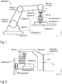
- a robot-assisted grinding device comprises a manipulator 1 (for example an industrial robot) and a grinding machine 10 with a rotating grinding wheel 11, the grinding machine 10 being coupled to the tool center point (TCP) of the manipulator 1 via a linear actuator 20.
- the manipulator can be constructed from four segments 2a, 2b, 2c and 2d, which are each connected via joints 3a, 3b and 3c.
- the last segment 2d is usually rigidly connected to a foundation B (which, however, does not necessarily have to be the case).
- the joint 3c connects the segments 2d and 2c.
- the joint 3c can be biaxial and allow the segment 2c to be rotated about a horizontal axis of rotation (elevation angle) and a vertical axis of rotation (azimuth angle).
- the joint 3b connects the segments 2b and 2c and enables a pivoting movement of the segment 2b relative to the position of the segment 2c.
- the hinge 3a connects the segments 2a and 2b.
- the joint 3a can be biaxial and therefore (similar to the joint 3c) enable a pivoting movement in two directions.
- the TCP has a fixed relative position to segment 2a, which usually also comprises a swivel joint (not shown) that enables a rotary movement about a longitudinal axis A of segment 2a (in Fig.
- Each axis of a joint is assigned an actuator which can cause a rotary movement about the respective joint axis.
- the actuators in the joints are controlled by a robot controller 4 in accordance with a robot program.
- the TCP can be positioned anywhere (within certain limits) (with any orientation of the axis A).
- the manipulator 1 is usually position-controlled, ie the robot controller can determine the pose (position and orientation) of the TCP and move it along a predefined trajectory. Industrial robots and the position control of the TCP are known per se and are therefore not explained further here. If the actuator 20 abuts an end stop, the pose of the TCP also defines the pose of the grinding tool. As already mentioned at the beginning, the actuator 20 serves to set the contact force (process force) between the tool (grinding wheel 11) and workpiece W to a desired value during the grinding process.
- process force process force
- a direct control of the process force by the manipulator 1 is usually too imprecise for grinding applications, since the high inertia of the segments 2a-2c of the manipulator 1 means that compensation of Force peaks (eg when placing the grinding tool on the workpiece 40) are practically not possible with conventional manipulators.
- the robot controller is designed to regulate the pose (position and orientation) of the TCP, while regulating the contact force (see also Fig. 2 , Contact force F K ) can only be produced by the actuator 20 (but not absolutely necessary), which is coupled between the grinding machine 10 and the manipulator 1.
- the contact force F K between the tool (grinding wheel 11) and workpiece W can be set during the grinding process with the aid of the (linear) actuator 20 and a force control unit (which can be implemented, for example, in the controller 4) such that the contact force F K between the grinding tool and workpiece W corresponds to a specifiable setpoint.
- the contact force is a reaction to the actuator force F A with which the linear actuator 20 presses on the workpiece surface. If there is no contact between workpiece 40 and tool, actuator 20 moves against an end stop (in.) Due to the lack of contact force F K Fig. 1 not shown or integrated in the actuator 20).
- the position control of the manipulator 1 (which can also be implemented in the controller 4) can work completely independently of the force control of the actuator 20.
- the actuator 20 is not responsible for the positioning of the grinding machine 10, but only for setting and maintaining the desired contact force during the grinding process and for detecting contact between the tool (grinding machine 10 with grinding wheel 11) and workpiece W.
- a contact can be recognized, for example , if the deflection of the actuator 20 starting from the end stop is none, or the change in the deflection of the actuator 20 becomes negative.
- the actuator can be a pneumatic actuator and can have, for example, a double-acting pneumatic cylinder.
- pneumatic actuators can also be used, such as bellows cylinders and air muscles.
- electric direct drives can also be considered.
- the force control can be implemented in a manner known per se with the aid of a control valve, a controller (implemented in the control 4) and a compressed air store.
- the concrete implementation is not important for the further explanation and is therefore not described in more detail.
- actuator 20 is not needed and can be omitted. In this case, the robot / manipulator 1 can regulate the process force directly.
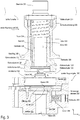
- FIG. 2 The example shown is between the actuator 20 and the outermost segment 2a of the manipulator 1 (see also Fig. 1 )
- a bracket 21 is arranged, which has approximately an L-shape.
- the purpose of the holder 21 is that the linear actuator 20 does not have to be mounted on the manipulator 1 coaxially to the axis A of the segment 2a (as in FIG Fig. 1 shown), but can be tilted by an angle of, for example, 90 °, so that the axis of rotation R of the grinding machine is essentially parallel to the axis A.
- the holder can also be omitted (actuator 20 is then mounted directly on the manipulator 1) or a holder can be used which has an angle other than 90 °.
- the location of the local coordinate system of the grinding machine is also shown.
- the axis of rotation R of the grinding machine is equal to the z-axis, and the linear actuator 20 acts along the x-axis.
- the tool for example the grinding wheel 11
- the drive for example the motor of the grinding machine 10
- the tool is connected to a first coupling part of the shaft coupling 30 and the drive shaft of the motor is connected to a second coupling part of the shaft coupling 30.
- the first coupling part can be regarded as a special shaft stub on which the tool (grinding wheel 11) is mounted.
- a robot can automatically change the tool, whereby the assembly consisting of tool and the first coupling part is always changed together.
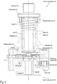
- Fig. 3 shows an exemplary implementation of a shaft coupling 30 (in a disengaged state), which can be used for an automatic, robot-assisted changing of grinding wheels.
- the shaft coupling has a first coupling part 310 and a second coupling part 350.
- the first coupling part 310 is connected to a grinding wheel 11, for example by means of a screw connection.
- a grinding wheel 11 is plugged onto one end of a shaft 330 and is fastened by means of a nut (not shown) which is attached to an Thread 332 provided shaft end is screwed, fixed, so that the grinding wheel 11 is clamped between the nut and a shaft shoulder 331 of the shaft 330.
- the second coupling part 350 has a hub 370, in which the drive shaft of the grinding machine 10 (in Fig. 3 not shown) and can be attached in a conventional manner via a key inserted into the groove 359.
- the two coupling parts 310 and 350 can be connected by means of a conical seat (outer cone 322 on the first coupling part 310 and inner cone 362 on the second coupling part 350). How the two coupling parts 310 and 350 can engage and be fixed to one another is described below with reference to FIG Fig. 4-7 explained in more detail. First, the structure of the first coupling part 310 is discussed in more detail.
- the first coupling part can be seen as a type of telescopic shaft, which is constructed, among other things, from the shaft 330 (to which the grinding wheel 11 is fixed) and a hollow shaft 320, the shaft 330 and the hollow shaft 320 being axially displaceable relative to one another (along the axis of rotation R) ,
- the hollow shaft 320 can be moved relative to the shaft 330 between two end positions.
- a sleeve 335 is arranged coaxially to the shaft 330, the sleeve 335 and the shaft 330 being rigidly connected to one another, for example via a screw connection 333 which connects a shaft section 331 of the shaft 330 to the sleeve 335.
- the outer and inner diameters of the hollow shaft 320 are dimensioned such that the hollow shaft 320 can slide between the shaft 330 and the sleeve 320 (in the axial direction).
- the inner diameter of the sleeve 335 and the outer diameter of the hollow shaft 320 can form a clearance fit .
- the inner diameter of the hollow shaft 320 and the outer diameter D 1 of the shaft 330 can also form a clearance fit.
- a key 336 which is inserted into a groove 337 in the shaft 330, prevents rotation between the hollow shaft 320 and the shaft 330.
- the hollow shaft 320 is displaceable relative to the shaft 330, a first end position of the hollow shaft 320 being formed by a shaft shoulder 338 of the shaft 330 and a second end position of the hollow shaft 320 being formed by an end face of the sleeve 335, which serves as a stop 340.
- the hollow shaft 320 is inserted as far as possible into the sleeve 335, and a shaft shoulder 323 of the hollow shaft 320 bears against the stop 340.
- the hollow shaft 320 protrudes out of the sleeve 335 at most and a shaft shoulder in the interior of the hollow shaft lies against a shaft shoulder 338 of the shaft 330.
- a spring 334 is arranged so that the Spring force pushes the hollow shaft 320 out of the sleeve 335 and presses in the axial direction against the shaft shoulder 338.
- a shaft section at the lower end of the shaft 330 has a diameter D 2 , which can be slightly smaller than the diameter D 1 .
- a cone 341 is provided on the lower end face of the shaft 330, which has a maximum diameter D 3 that is larger than the diameter D 2 , so that a shaft shoulder 339 is formed on the rear side of the cone 341.
- This shaft shoulder 339 serves to axially fix the first coupling part 310 to the second coupling part 350 (cf., for example Fig. 7 )
- the cone 341 is created, for example, by chamfering the peripheral edge at one end of the shaft 330. The chamfer forms the cone 341 mentioned.
- the second coupling part 350 can have a two-part housing (upper part 361, lower part 351), which can, for example, be fixed to one another (for example by means of screws).
- the upper part 361 of the housing has a central inner cone 362 (ie a conical hub) which, together with the corresponding outer cone 322 (on the hollow shaft 320) of the first coupling part 310, can form a conical seat (see for example Fig. 7 ).
- the inner cone 362 runs through the entire upper part 361 and is rotationally symmetrical with respect to the axis of rotation R.
- a radially (transversely to the axis of rotation R and relative to the housing of the second coupling part 350) displaceable securing element 352 is arranged, which by means of a spring 354 is pressed against an end stop in the lower part 351 of the housing.
- the spring 354 is arranged in a radial bore in the lower part 351 of the housing, which is closed with a screw 353. The spring force of the spring 354 thus acts between the securing element 352 and the screw 353.
- the lower part 351 of the housing has a central hole which forms a hub 370 for a motor shaft of the grinding machine 10 (cf. Fig. 2 ).
- the hub 370 can form a groove 359 for receiving a feather key (not shown).
- any other shaft-hub connection can be used for mounting the second coupling part 350 on the motor shaft of the grinding machine 10.
- the securing element has a central opening 355 below the conical hub (inner cone 362), through which the axis of rotation R extends.
- the upper edge of the opening 355 is chamfered so that the chamfer forms a small inner cone 356.
- the lower edge 357 of the opening 355 lies against the shaft shoulder 339 of the shaft 330 of the first coupling part 310 in order to fix the two coupling parts 310, 350 to one another (cf. Fig. 7 ).
- the central opening 355 in the securing element 352 is shown in the illustration Fig. 3 slightly eccentric with respect to the axis of rotation R.
- the two coupling parts 310 and 350 of the shaft coupling Fig. 3 shown in several (intermediate) positions during a coupling process.
- the first coupling part 310 together with a grinding wheel 11 mounted thereon lies on a base plate (cf. Fig. 10 ), and the second coupling part 350 is pressed by the robot onto the first coupling part 310 from above (in this case, the position of the shaft coupling is exactly reversed ( upside down ) as in FIG Fig. 3 ) Shown.
- the first coupling part 310 together with a grinding wheel 11 mounted thereon can also be arranged hanging on a base plate, and one and the second coupling part 350 is pressed onto the first coupling part 310 from below by the robot (in this case, the position of the shaft coupling is the same as in FIG Fig. 3 ) Shown.
- An inclined position of the shaft coupling when engaging and disengaging is also possible.
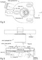
- Fig. 4 represents a state in which the second coupling part 350 is already partially plugged onto the first coupling part 310 along the axis of rotation R (in the z direction).
- the conical shaft cut 321 (outer cone 322) of the hollow shaft 320 of the first coupling part 310 is inserted into the conical opening (inner cone 362) of the upper part 361 of the housing of the second coupling part 350.
- the chamfered end (cone 341) of the shaft 330 of the first coupling part 310 touches the (eg chamfered, chamfered) edge (inner cone 356) of the central opening 355 of the securing element 352.
- the chamfers 341, 456 can slide on one another during that Securing element 352 is moved transversely to the axis of rotation.
- Fig. 5 represents a state in which the second coupling part 350 is completely plugged onto the first coupling part 310 along the axis of rotation R (in the z direction).
- the conical shaft cut 321 (outer cone 322) of the hollow shaft 320 of the first coupling part 310 and the conical hub (inner cone 362) of the upper part 361 of the housing of the second coupling part 350 form a conical seat (in Fig. 5 labeled with 322/362).
- the situation shown is the securing element 352 compared to that in FIG Fig. 4 situation shown by a shift d to the right (in the direction of the x-axis).
- This shifting of the securing element 352 is supported by the fact that the outer cone 341 (or the chamfer) on the end piece of the shaft 330 and the inner cone 356 on the edge of the opening 355 in the securing element 352 are matched to one another, as a result of which the conical surfaces can slide better on one another.
- the conical shape instead of the conical shape, another oblique or curved shape is also possible. It is also sufficient if only one of the two parts (shaft 330, securing element 352) is conical, oblique or curved at the contact point.
- the two coupling parts 310, 350 are frictionally connected via the conical seat 322/362.
- the conical seat is preloaded in the axial direction (z direction) with the spring force k F ⁇ ⁇ z.
- the securing element 352 is displaced against the force of the spring 354 until the securing element 352 no longer engages on the shaft shoulder 339 of the shaft 330 and consequently the spring 334 Shaft 330 can push back into the starting position (shaft shoulder 338 lies against a shoulder of the hollow shaft 320).
- Figure 8 is a detailed view of the locking element 352 in the engaged state on the shaft shoulder 339 of the shaft 330.
- the edge 357 of the opening 355 of the locking element 352 bears against the shaft shoulder 339 and thereby locks a snap back of the shaft 330 due to the spring force of the spring 334 (cf. Fig. 7 ).
- the elongated holes provided in the securing element 352 only serve to guide the securing element transversely to the axis of rotation R (transversely to the z direction).
- the manipulator can move the grinding tool to a defined storage position.
- a stop 520 is arranged in the vicinity and in a defined position relative to the storage position. For example, by rotating the shaft coupling around the axis of rotation R of the shaft 330, the robot can position the shaft coupling such that the stop 520 fixes the securing element 352 against the force of the spring 354 (see Fig. 7 , in Fig. 8 not shown) presses into the second coupling part 350 and releases the latching connection between the securing element 352 and the shaft shoulder 339 of the shaft 330.
- the stop 520 can also be spring-mounted, the spring stiffness of the stop being greater than the spring stiffness of the spring 354.
- Figure 9 shows an alternative embodiment of the shaft coupling, in which the spring 334, which provides the spring force for the prestressing of the conical seat, does not look like in the example Fig. 7 is arranged in the first coupling part 310, but in the second coupling part 350.
- the function is essentially the same as in the previous example Fig. 3-7 ,
- the first coupling part 310 can be made simpler (because the spring is omitted).
- the first coupling part 310 can be a rigid component.
- the spring 334 is arranged between the upper part 361 and the lower part 351 of the housing of the second coupling part 350.
- the lower part 351 When inserting of the first coupling part 310 into the second coupling part 350, the lower part 351 is pressed towards the upper part 361 against the spring force of one or more springs 334 ′ until the securing element engages on a shaft shoulder of the shaft 330 of the first coupling part, whereby the two coupling parts 310 and 350 are connected to one another be connected and the conical seat is biased by the spring force.
- the shaft coupling is released in the same way as in the previous example (see e.g. Fig. 8 ).
- Figure 10 illustrates an example of a changing station 50 which is suitable for automatic, robot-assisted changing of tools (for example grinding wheels 11 including the first coupling part 310).
- Figure 11 shows a detail of the changing station 50 with an inserted shaft coupling 30.
- a robot / manipulator eg in a robot cell
- several similar changing stations eg next to each other
- different tools can be made available for the (processing) process carried out by the robot / manipulator;
- By simply changing the shaft (with the tool attached to it) several (different) work steps can be carried out at one workstation with a robot / manipulator.
- the changing station comprises a base 501, which is generally stationary and has a defined position, which is known to the robot controller.
- a support plate 510 is mounted on the base 501.
- the support plate 510 is displaceably mounted on the base 501 by means of set screws 516, which are screwed to the base 501 and are guided through corresponding holes in the support plate 510 (against the z direction).
- the support plate 510 is pressed against the base 501 by means of springs 515, which act between the support plate 510 and nuts screwed onto the threaded pins 516.
- the support plate 510 can therefore be raised against the force of the springs 515 from the base 501.
- the support plate 510 is rigidly connected to the base 501 or the base 501 also serves as the support plate 510.
- the cover 505 is also optional.
- a recess 511 is provided in the support plate 510, into which the robot (see Fig. 1 , Manipulator 10) can insert the shaft coupling 30 laterally.
- the shaft coupling is in the y direction (see arrow in Fig. 10 ) inserted into the recess 511.
- this can be a have a circular contour.
- the upper edge of the recess 511 can be chamfered.
- the chamfer 512 forms a cone on which the first coupling part 310 of the shaft coupling 30 can rest. More specifically, the cone 345 of the hollow shaft 320 of the first coupling part 310 (see e.g. Fig.
- At least one stop 520 and a proximity switch 521 are arranged on the support plate 510.
- the function of the stop and the proximity switch 521 is shown in FIG Fig. 11 clear.
- FIG. 11 A situation is shown in which the shaft coupling 30 has just been rotated such that the outer end of the securing element 352 lies against the stop 520. The rotation of the shaft coupling 30 against the stop has been made with reference to FIG Fig. 8 explained.
- the stop 520 presses the securing element 352 into the second coupling part 350 and releases the latching connection with the shaft 330.
- the tool 11 with the first coupling part 310 remains in the changing station 50 and can be used later (for example manually). to be replaced by a new tool 11.
- the robot moves the grinding machine 10 to a changing station 50 with an inserted new grinding wheel 11 (including the first coupling part 310) such that the axis of rotation R of the motor of the grinding wheel 11 is coaxial with the axis of rotation of the tool to be coupled (cf. , Fig. 3 ).
- the process of pairing has already been made with reference to Fig. 3-7 described in detail.
- the securing element 352 moves away from the proximity switch 521 by a distance d (cf. Fig. 4-5 ) and then back to the starting position (cf. Fig. 6-7 ).
- This movement (forwards, backwards and forwards again) of the securing element 352 can be detected by the proximity switch 521 and in this way a proper coupling of the two coupling parts 310, 350 are monitored.
- Proximity switches 521 usually detect the presence of the securing element 352 via a mechanical contact.
- non-contact (eg inductive, capacitive or optical) proximity switches can also be used, which are also generally referred to as proximity sensors .
- a safety feature is the resilient mounting of the support plate 510 on the base 501. If the release of the shaft coupling 30 fails (for whatever reason), then the robot, when attempting to lift the grinding machine 11 with the second coupling part 350, will at the same time also Raise the support plate 510 against the spring force of the springs 515, since the non-disengaged first coupling part 310 takes the support plate with it when the coupling is inserted into the recess 511. This lifting of the support plate 510 can be detected by means of a sensor.
- a suitable sensor for this is e.g. a contact switch, a proximity sensor, a light sensor (which is covered by the platen when it is not raised), etc.
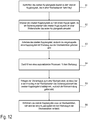
- FIG. 12 is a flowchart illustrating the sequence of a shaft change process, that is, the engagement of a shaft coupling such as a Fig. 3-7 shown and the release of the shaft coupling such as in Fig. 11 shown.
- a shaft of the first coupling part 310, see Fig. 3
- first coupling part 310 lies in recess 511 of the exchange station 50.
- a manipulator 1 cf. Fig. 1
- a machine tool with the second coupling part is moved towards the changing station so that the two coupling parts are aligned essentially coaxially (see Fig. 12 , Step S1).
- the manipulator can then press the two coupling parts against each other until a securing element of the second coupling part engages on a shaft shoulder of the first coupling part (see Fig. 12 , Step S2, cf. also Fig. 6-7 , Securing element 352 engages on shaft shoulder 339).
- the manipulator can then lift the second coupling part (and thus the entire shaft coupling including tools) and remove it from the exchange station ( Fig. 12 , Step S3).
- the second coupling part is moved out of the recess 511.
- the coupled tool can then be used for the automated machining of a workpiece (see Fig. 12 , Step S4).
- the shaft coupling can be reinserted in a changing station (in the same as before or in another), whereby when inserting over one Stop in the exchange station (cf. Fig. 10 , Stop 520) the securing element is actuated, as a result of which the latching connection is released (cf. state before being released in Fig. 7 , State after loosening in Fig. 6 ), please refer Fig. 12 , Step S5. Finally, the manipulator can move the released second coupling part out of the changing station and the first coupling part with the (used) tool remains in the changing station ( Fig. 12 , Step S6).
- the exemplary embodiments of the shaft coupling and the change station described here do not need their own energy supply (for example electrical current or compressed air). Consequently, the shaft coupling does not require any supply lines for electricity, compressed air and the like. Connectors, sliding contacts, etc. can be avoided.
- the exchange station (see Fig. 10 ) does not need its own drive.
- An exemplary embodiment relates to a shaft coupling which has a first coupling part with a shaft and a conical shaft section (cf. for example Fig. 3 ).
- a tool for example a grinding wheel, a drill, etc.
- the shaft coupling has a second coupling part which has a conical hub, into which the conical shaft section of the first coupling part can be inserted to form a conical seat.
- the second coupling part furthermore has a securing element which can be moved transversely to an axis of rotation of the shaft coupling and which is arranged such that it can snap into place on the shaft shoulder of the shaft (cf. Fig. 6 and 7 ).
- At least one spring is arranged in the shaft coupling in such a way that it generates a spring force which, when the securing element is engaged, acts on the conical seat in the axial direction and prestresses it.
- the spring that biases the conical seat can either be in the first coupling part (see Fig. 3 , Spring 334) or in the second coupling part (see Fig. 9 , Spring 334 ') may be provided.
- the first coupling part has a hollow shaft which is axially displaceably mounted on the shaft.
- the conical shaft section is part of the hollow shaft (see Fig. 3 , Shaft section 321 outside on the hollow shaft 320).
- the spring is contained in the first coupling part and arranged so that the hollow shaft is displaced against the spring force of the spring on the shaft when the conical shaft section is inserted into the conical hub (see 4 to 6 ).
- the relative movement between the hollow shaft and the shaft penetrates the shaft shoulder of the shaft into the second coupling part until the securing element can snap into the shaft shoulder and form a latching connection.
- the shaft can have a further shaft shoulder, which forms an end stop for the hollow shaft, the spring force of the spring pressing the hollow shaft against the end stop.
- a feather key can be arranged between the shaft and the hollow shaft so that an axial displacement (relative movement) between the shaft and the hollow shaft is possible, but a rotation between the shaft and the hollow shaft is blocked.
- the spring that prestresses the conical seat can also be arranged in the second coupling part (see Fig. 9 , Spring 334 ').
- the second coupling part comprises a lower part and an upper part which is axially displaceable relative to the lower part.
- the conical hub is arranged in the upper part, and the at least one spring is arranged between the lower part and the upper part in such a way that when the conical shaft section is inserted into the conical hub, the lower part is displaced towards the upper part against the spring force of the spring (see, for example Fig. 9 , Spring 334 'acts between lower part 351 and upper part 361 and prestresses the conical seat).
- the securing element can protrude from the second coupling part. Furthermore, the securing element can have a (central) opening, into which the shaft can be inserted until the securing element can snap into the shaft shoulder of the shaft, the latching connection preventing the shaft from being pulled back out of the opening.
- an edge of the central opening in the securing element is moved behind the shaft shoulder of the shaft (transversely to the axis of rotation of the shaft coupling, cf. 6 to 7 ).
- the spring force prestresses the conical shaft section against the conical hub.
- the edge of the opening in the securing element and a peripheral edge of the shaft can each be chamfered. The chamfer on the edge of the shaft and the chamfer on the edge of the opening can slide against one another when the shaft is inserted into the opening while the securing element is being displaced.
- Another exemplary embodiment relates to a system with a manipulator and a machine tool with a motor shaft for driving a tool.
- the machine tool is coupled to the manipulator and can be positioned by it.
- the system comprises a shaft coupling which can be constructed in accordance with one of the exemplary embodiments described here.
- Another exemplary embodiment relates to a system with a shaft coupling, which can be constructed in accordance with one of the exemplary embodiments described here, and with at least one changing station.
- the exchange station has a support plate with a recess.
- the recess defines a storage position in which the first coupling part of the shaft coupling can be inserted into the recess.
- the conical shaft section of the first coupling part protrudes from the support plate.
- the system can also have a stop arranged on the support plate.
- the system can have a proximity sensor which is arranged such that it can detect a displacement of the securing element during the coupling of the two coupling parts.
- the support plate can be resiliently mounted on a base (see e.g. Fig. 10 , Springs 515), which is why the support plate can be raised relative to the base (safety feature).
- a further exemplary embodiment relates to a method according to which a manipulator is used to initially align a second coupling part of a shaft coupling coaxially with a first coupling part of the shaft coupling (see, for example, Fig. 3 ), which is available in a change station (see e.g. Fig. 11 ).
- the second coupling part is then pressed onto the first coupling part until a securing element of the second coupling part engages on a shaft shoulder of the first coupling part and forms a latching connection (see, for example Fig. 6 and 7 , such as Fig. 9 ).
- the first coupling part (with the tool) can also be lifted out of the changing station by lifting the second coupling part.
- the manipulator can be used to carry out an automated (machining) process on a workpiece.
- the shaft coupling is then connected to the Exchange station (or another exchange station) inserted in such a way that the securing element of the second coupling part can be actuated via a stop in the respective exchange station, as a result of which the latching connection is released.
- the second coupling part is removed from the respective changing station by means of the manipulator, while the first coupling part remains in the changing station.
- a conical shaft section of the first coupling part can be inserted into a conical hub of the second coupling part, whereby a conical seat is formed.
- the shaft shoulder of the first coupling part can be pushed into the second coupling part until the securing element engages on the shaft shoulder so that the spring force prestresses the conical seat in the engaged state.
- the securing element is moved transversely to an axis of rotation of the shaft coupling, and this movement can be detected by means of a proximity sensor.
- the shaft shoulder can be pressed away from the securing element using a spring (see e.g. Fig.
- the shaft coupling After inserting the shaft coupling into the changing station (or another changing station), the shaft coupling can be rotated about its axis of rotation until the end of the securing element protruding from the second coupling part lies against the stop of the changing station.
Applications Claiming Priority (2)
| Application Number | Priority Date | Filing Date | Title |
|---|---|---|---|
| DE102017121171.3A DE102017121171A1 (de) | 2017-09-13 | 2017-09-13 | Verfahren und system zum automatischen wechseln von wellen |
| PCT/EP2018/074799 WO2019053155A1 (de) | 2017-09-13 | 2018-09-13 | Verfahren und system zum automatischen wechseln von wellen |
Publications (2)
| Publication Number | Publication Date |
|---|---|
| EP3481605A1 EP3481605A1 (de) | 2019-05-15 |
| EP3481605B1 true EP3481605B1 (de) | 2020-01-22 |
Family
ID=63708289
Family Applications (1)
| Application Number | Title | Priority Date | Filing Date |
|---|---|---|---|
| EP18779239.5A Active EP3481605B1 (de) | 2017-09-13 | 2018-09-13 | Verfahren und system zum automatischen wechseln von wellen |
Country Status (7)
| Country | Link |
|---|---|
| US (1) | US11135729B2 (zh) |
| EP (1) | EP3481605B1 (zh) |
| JP (1) | JP7194175B2 (zh) |
| KR (1) | KR102158959B1 (zh) |
| CN (1) | CN111093915B (zh) |
| DE (1) | DE102017121171A1 (zh) |
| WO (1) | WO2019053155A1 (zh) |
Families Citing this family (6)
| Publication number | Priority date | Publication date | Assignee | Title |
|---|---|---|---|---|
| JP2022542782A (ja) * | 2019-08-07 | 2022-10-07 | ライトハンド ロボティックス, インコーポレイテッド | ロボットデバイスの構成 |
| CN111940820B (zh) * | 2020-08-07 | 2021-08-24 | 国网江苏省电力有限公司常州供电分公司 | 便于更换锁定的通用通讯接口 |
| CN113103042B (zh) * | 2021-03-19 | 2022-03-29 | 上海航天精密机械研究所 | 面向生产线的薄壁舱体车铣复合加工的自动化装夹方法 |
| CN113508686B (zh) * | 2021-05-27 | 2022-04-12 | 中国农业大学 | 一种串番茄采摘末端执行器、机器人及其采摘方法 |
| CN113386152B (zh) * | 2021-06-29 | 2022-09-23 | 重庆大学 | 一种六轴打磨机器人 |
| TWI779932B (zh) * | 2021-11-22 | 2022-10-01 | 博府智造股份有限公司 | 恆力式主軸可快速轉換力控軸向之加工裝置及其加工方法 |
Family Cites Families (31)
| Publication number | Priority date | Publication date | Assignee | Title |
|---|---|---|---|---|
| JPS5148876A (en) * | 1974-10-23 | 1976-04-27 | Toyoda Machine Works Ltd | Jidokogukokansochi |
| JPS5292175A (en) * | 1976-01-29 | 1977-08-03 | Toyoda Mach Works Ltd | Machine tool which is provided with automatic tool changing device |
| US4399603A (en) * | 1980-11-17 | 1983-08-23 | Giddings & Lewis, Inc. | Power grip tool exchange arm for machining center |
| US4922591A (en) * | 1984-03-20 | 1990-05-08 | Carboloy Inc. | Tool storage and changing system |
| EP0340369B1 (fr) * | 1988-05-06 | 1992-03-04 | Emile Pfalzgraf | Dispositif de montage d'attachements, de porte-outils et d'outils à application cône et face, notamment pour centres d'usinage et de tournage avec changeurs automatiques ou manuels d'outils à queue conique, en particulier au cône 7/24e |
| US4897014A (en) * | 1988-09-06 | 1990-01-30 | Harbor Branch Oceanographic Institution, Inc. | Device for interchange of tools |
| US5002500A (en) * | 1990-03-02 | 1991-03-26 | General Motors Corporation | Quick connect/disconnector for high amperage current |
| US5294209A (en) * | 1991-07-25 | 1994-03-15 | Yamaha Hatsudoki Kabushiki Kaisha | Tool attaching device |
| US5220749A (en) * | 1991-11-07 | 1993-06-22 | The University Of Rochester | Grinding apparatus |
| DE9203374U1 (zh) * | 1992-03-13 | 1993-07-22 | Staedele, Berta, 88697 Bermatingen, De | |
| JPH0636738U (ja) * | 1992-10-19 | 1994-05-17 | 嘉一 佐藤 | 自動工具交換装置 |
| TW251251B (zh) * | 1993-12-08 | 1995-07-11 | Honda Motor Co Ltd | |
| US5613929A (en) * | 1995-06-07 | 1997-03-25 | Hurco Companies, Inc. | Machine tool with bar-spindle and DIN standard toolholder changer |
| JP3044456B2 (ja) * | 1995-11-27 | 2000-05-22 | 本田技研工業株式会社 | タレット式工作機械 |
| ITTO980462A1 (it) * | 1998-05-29 | 1999-11-29 | Brown & Sharpe Dea Spa | Gruppo di collegamento di un attrezzo di misura ad una testa di misura atta ad essere movimentata da un robot di misura |
| US6149562A (en) * | 1999-10-27 | 2000-11-21 | Hurco Companies, Inc. | Manual tool changing apparatus |
| CA2351460C (en) * | 2000-06-23 | 2006-11-14 | Nippei Toyama Corporation | Method and apparatus for supplying lubricant |
| KR200392408Y1 (ko) * | 2005-05-17 | 2005-08-17 | 임창영 | Cnc 세혈방전가공기의 자동공구교환장치의 툴 척 홀더 |
| JP2007090411A (ja) * | 2005-09-30 | 2007-04-12 | Kikusui Seisakusho Ltd | 回転式粉末圧縮成形機 |
| JP5125638B2 (ja) * | 2008-03-12 | 2013-01-23 | 株式会社安川電機 | 双腕ロボット |
| CN101697929B (zh) * | 2009-11-03 | 2011-04-27 | 昆山市工业技术研究院有限责任公司 | 一种机械臂末端工具快速切换装置 |
| DE102010030642A1 (de) * | 2010-06-09 | 2011-12-15 | Robert Bosch Gmbh | Handwerkzeugmaschine mit einer Werkzeugaufnahme |
| CN102059564A (zh) * | 2010-12-13 | 2011-05-18 | 江南大学 | 快换工作夹头 |
| US8667660B2 (en) * | 2011-05-17 | 2014-03-11 | Kennametal Inc. | Quick change clamping device |
| EP2564994A1 (de) * | 2011-09-02 | 2013-03-06 | Siemens VAI Metals Technologies GmbH | Kuppeleinrichtung zum automatisierten Ankuppeln eines Werkzeughalters an einen Werkzeugaufnehmer |
| CN102490181B (zh) * | 2011-11-21 | 2014-04-23 | 哈尔滨工业大学 | 用于空间在轨模块更换的抓持机构 |
| DE102012213207A1 (de) * | 2012-07-26 | 2014-01-30 | Deckel Maho Pfronten Gmbh | Werkzeugköcher zum Aufnehmen und Verriegeln eines Werkzeugkegels an einem Werkzeugmagazin, Entriegelungseinrichtung und Werkzeugmagazin |
| CN104149102B (zh) * | 2014-07-04 | 2015-09-09 | 哈尔滨博强机器人技术有限公司 | 机器人工具自锁式快速换装盘 |
| CN105128022B (zh) * | 2015-09-10 | 2017-01-18 | 西安交通大学 | 一种机器人智能末端自动更换装置 |
| CN205415662U (zh) * | 2016-04-05 | 2016-08-03 | 山东大学 | 一种机器人末端快速更换装置 |
| US10065327B1 (en) * | 2017-10-06 | 2018-09-04 | Chih Hsiang Chen | Robotic arm capable of changing clamping heads rapidly |
-
2017
- 2017-09-13 DE DE102017121171.3A patent/DE102017121171A1/de not_active Withdrawn
-
2018
- 2018-09-13 WO PCT/EP2018/074799 patent/WO2019053155A1/de unknown
- 2018-09-13 JP JP2020514723A patent/JP7194175B2/ja active Active
- 2018-09-13 CN CN201880059795.XA patent/CN111093915B/zh active Active
- 2018-09-13 KR KR1020207007971A patent/KR102158959B1/ko active IP Right Grant
- 2018-09-13 US US16/646,711 patent/US11135729B2/en active Active
- 2018-09-13 EP EP18779239.5A patent/EP3481605B1/de active Active
Non-Patent Citations (1)
| Title |
|---|
| None * |
Also Published As
| Publication number | Publication date |
|---|---|
| CN111093915B (zh) | 2023-01-10 |
| CN111093915A (zh) | 2020-05-01 |
| JP7194175B2 (ja) | 2022-12-21 |
| KR20200035315A (ko) | 2020-04-02 |
| EP3481605A1 (de) | 2019-05-15 |
| JP2020533189A (ja) | 2020-11-19 |
| WO2019053155A1 (de) | 2019-03-21 |
| US11135729B2 (en) | 2021-10-05 |
| KR102158959B1 (ko) | 2020-09-23 |
| US20200376683A1 (en) | 2020-12-03 |
| DE102017121171A1 (de) | 2019-03-14 |
Similar Documents
| Publication | Publication Date | Title |
|---|---|---|
| EP3481605B1 (de) | Verfahren und system zum automatischen wechseln von wellen | |
| EP3325214B1 (de) | Werkzeugmaschine zum robotergestützten bearbeiten von oberflächen | |
| DE69919874T2 (de) | Spindeleinheit zum herstellen eines lochs in einem werkstück aus faserverstärktem material | |
| DE102020124757B4 (de) | Robotersystem mit rekonfigurierbarer endeffektor-baugruppe | |
| DE102018103805A1 (de) | Robotersystem mit rekonfigurierbarer endeffektor-baugruppe | |
| EP3765239B1 (de) | Drehzahlsteuerung beim robotergestützten schleifen | |
| EP3416787A1 (de) | Effektoreinheit für einen roboter, arbeitsvorrichtung mit einem roboter und verfahren zum wechseln eines effektors bei robotern | |
| DE102011122040A1 (de) | Aufnahmevorrichtung für ein Werkzeug | |
| CH619629A5 (zh) | ||
| DE102016222506A1 (de) | Werkzeugwechselvorrichtung | |
| EP3980227A2 (de) | Ausgleich von lagetoleranzen beim der robotergestützten oberflächenbearbeitung | |
| EP2277671B1 (de) | Verfahren und Vorrichtung zum Wechseln von Fräsern an einem Industrieroboter | |
| DE102016009520A1 (de) | Bearbeitungssystem mit Werkzeugmaschine und Roboter zum Anbringen und Lösen eines Werkstücks | |
| DE102018126250A1 (de) | Montagewerkzeug und Montageverfahren | |
| DE602005005042T2 (de) | Werkstücksgreifvorrichtung für ein Werkzeughalter-System von einer Werkzeugmaschine | |
| EP2590778A2 (de) | Aktive universelle haltevorrichtung zur halterung eines werkstücks in einer universalspannvorrichtung | |
| EP3697567B1 (de) | Absaugung für schleifwerkzeug mit radialbürstenscheibe | |
| DE102019111049A1 (de) | System und Verfahren zum automatisierten Verschrauben von Schraubelementen | |
| EP4275801A1 (de) | Dichtmittelauftragstation und montagesystem zum verbinden von komponenten | |
| EP3682990A1 (de) | Sicherungsvorrichtung | |
| EP3600796B1 (de) | Endeffektor mit verschiebbarer schutzhülse zur werkstückbearbeitung und robotersystem mit einem endeffektor | |
| DE112019004638T5 (de) | Elektrischer Werkzeugwechsler | |
| EP1600252A2 (de) | Werkzeugantrieb, insbesondere zum automatischen Entgraten, Kantenbrechen oder Verputzen von Werkstücken | |
| EP3934862B1 (de) | Schnellspannsystem zur verbindung von werkzeugmaschinen mit einem roboter | |
| DE102018001131A1 (de) | Vorrichtung zum Abstützen eines zu bearbeitenden Werkstücks |
Legal Events
| Date | Code | Title | Description |
|---|---|---|---|
| STAA | Information on the status of an ep patent application or granted ep patent |
Free format text: STATUS: UNKNOWN |
|
| STAA | Information on the status of an ep patent application or granted ep patent |
Free format text: STATUS: THE INTERNATIONAL PUBLICATION HAS BEEN MADE |
|
| PUAI | Public reference made under article 153(3) epc to a published international application that has entered the european phase |
Free format text: ORIGINAL CODE: 0009012 |
|
| STAA | Information on the status of an ep patent application or granted ep patent |
Free format text: STATUS: REQUEST FOR EXAMINATION WAS MADE |
|
| 17P | Request for examination filed |
Effective date: 20190208 |
|
| AK | Designated contracting states |
Kind code of ref document: A1 Designated state(s): AL AT BE BG CH CY CZ DE DK EE ES FI FR GB GR HR HU IE IS IT LI LT LU LV MC MK MT NL NO PL PT RO RS SE SI SK SM TR |
|
| AX | Request for extension of the european patent |
Extension state: BA ME |
|
| GRAP | Despatch of communication of intention to grant a patent |
Free format text: ORIGINAL CODE: EPIDOSNIGR1 |
|
| STAA | Information on the status of an ep patent application or granted ep patent |
Free format text: STATUS: GRANT OF PATENT IS INTENDED |
|
| DAV | Request for validation of the european patent (deleted) | ||
| DAX | Request for extension of the european patent (deleted) | ||
| INTG | Intention to grant announced |
Effective date: 20190719 |
|
| GRAS | Grant fee paid |
Free format text: ORIGINAL CODE: EPIDOSNIGR3 |
|
| GRAJ | Information related to disapproval of communication of intention to grant by the applicant or resumption of examination proceedings by the epo deleted |
Free format text: ORIGINAL CODE: EPIDOSDIGR1 |
|
| GRAL | Information related to payment of fee for publishing/printing deleted |
Free format text: ORIGINAL CODE: EPIDOSDIGR3 |
|
| STAA | Information on the status of an ep patent application or granted ep patent |
Free format text: STATUS: REQUEST FOR EXAMINATION WAS MADE |
|
| GRAP | Despatch of communication of intention to grant a patent |
Free format text: ORIGINAL CODE: EPIDOSNIGR1 |
|
| STAA | Information on the status of an ep patent application or granted ep patent |
Free format text: STATUS: GRANT OF PATENT IS INTENDED |
|
| GRAA | (expected) grant |
Free format text: ORIGINAL CODE: 0009210 |
|
| STAA | Information on the status of an ep patent application or granted ep patent |
Free format text: STATUS: THE PATENT HAS BEEN GRANTED |
|
| INTC | Intention to grant announced (deleted) | ||
| INTG | Intention to grant announced |
Effective date: 20191204 |
|
| AK | Designated contracting states |
Kind code of ref document: B1 Designated state(s): AL AT BE BG CH CY CZ DE DK EE ES FI FR GB GR HR HU IE IS IT LI LT LU LV MC MK MT NL NO PL PT RO RS SE SI SK SM TR |
|
| REG | Reference to a national code |
Ref country code: GB Ref legal event code: FG4D Free format text: NOT ENGLISH |
|
| REG | Reference to a national code |
Ref country code: CH Ref legal event code: EP |
|
| REG | Reference to a national code |
Ref country code: AT Ref legal event code: REF Ref document number: 1226631 Country of ref document: AT Kind code of ref document: T Effective date: 20200215 |
|
| REG | Reference to a national code |
Ref country code: IE Ref legal event code: FG4D Free format text: LANGUAGE OF EP DOCUMENT: GERMAN |
|
| REG | Reference to a national code |
Ref country code: DE Ref legal event code: R096 Ref document number: 502018000667 Country of ref document: DE |
|
| REG | Reference to a national code |
Ref country code: NL Ref legal event code: MP Effective date: 20200122 |
|
| REG | Reference to a national code |
Ref country code: LT Ref legal event code: MG4D |
|
| PG25 | Lapsed in a contracting state [announced via postgrant information from national office to epo] |
Ref country code: NO Free format text: LAPSE BECAUSE OF FAILURE TO SUBMIT A TRANSLATION OF THE DESCRIPTION OR TO PAY THE FEE WITHIN THE PRESCRIBED TIME-LIMIT Effective date: 20200422 Ref country code: PT Free format text: LAPSE BECAUSE OF FAILURE TO SUBMIT A TRANSLATION OF THE DESCRIPTION OR TO PAY THE FEE WITHIN THE PRESCRIBED TIME-LIMIT Effective date: 20200614 Ref country code: RS Free format text: LAPSE BECAUSE OF FAILURE TO SUBMIT A TRANSLATION OF THE DESCRIPTION OR TO PAY THE FEE WITHIN THE PRESCRIBED TIME-LIMIT Effective date: 20200122 Ref country code: FI Free format text: LAPSE BECAUSE OF FAILURE TO SUBMIT A TRANSLATION OF THE DESCRIPTION OR TO PAY THE FEE WITHIN THE PRESCRIBED TIME-LIMIT Effective date: 20200122 Ref country code: NL Free format text: LAPSE BECAUSE OF FAILURE TO SUBMIT A TRANSLATION OF THE DESCRIPTION OR TO PAY THE FEE WITHIN THE PRESCRIBED TIME-LIMIT Effective date: 20200122 |
|
| PG25 | Lapsed in a contracting state [announced via postgrant information from national office to epo] |
Ref country code: BG Free format text: LAPSE BECAUSE OF FAILURE TO SUBMIT A TRANSLATION OF THE DESCRIPTION OR TO PAY THE FEE WITHIN THE PRESCRIBED TIME-LIMIT Effective date: 20200422 Ref country code: LV Free format text: LAPSE BECAUSE OF FAILURE TO SUBMIT A TRANSLATION OF THE DESCRIPTION OR TO PAY THE FEE WITHIN THE PRESCRIBED TIME-LIMIT Effective date: 20200122 Ref country code: IS Free format text: LAPSE BECAUSE OF FAILURE TO SUBMIT A TRANSLATION OF THE DESCRIPTION OR TO PAY THE FEE WITHIN THE PRESCRIBED TIME-LIMIT Effective date: 20200522 Ref country code: SE Free format text: LAPSE BECAUSE OF FAILURE TO SUBMIT A TRANSLATION OF THE DESCRIPTION OR TO PAY THE FEE WITHIN THE PRESCRIBED TIME-LIMIT Effective date: 20200122 Ref country code: GR Free format text: LAPSE BECAUSE OF FAILURE TO SUBMIT A TRANSLATION OF THE DESCRIPTION OR TO PAY THE FEE WITHIN THE PRESCRIBED TIME-LIMIT Effective date: 20200423 Ref country code: HR Free format text: LAPSE BECAUSE OF FAILURE TO SUBMIT A TRANSLATION OF THE DESCRIPTION OR TO PAY THE FEE WITHIN THE PRESCRIBED TIME-LIMIT Effective date: 20200122 |
|
| REG | Reference to a national code |
Ref country code: DE Ref legal event code: R097 Ref document number: 502018000667 Country of ref document: DE |
|
| PG25 | Lapsed in a contracting state [announced via postgrant information from national office to epo] |
Ref country code: ES Free format text: LAPSE BECAUSE OF FAILURE TO SUBMIT A TRANSLATION OF THE DESCRIPTION OR TO PAY THE FEE WITHIN THE PRESCRIBED TIME-LIMIT Effective date: 20200122 Ref country code: DK Free format text: LAPSE BECAUSE OF FAILURE TO SUBMIT A TRANSLATION OF THE DESCRIPTION OR TO PAY THE FEE WITHIN THE PRESCRIBED TIME-LIMIT Effective date: 20200122 Ref country code: SK Free format text: LAPSE BECAUSE OF FAILURE TO SUBMIT A TRANSLATION OF THE DESCRIPTION OR TO PAY THE FEE WITHIN THE PRESCRIBED TIME-LIMIT Effective date: 20200122 Ref country code: SM Free format text: LAPSE BECAUSE OF FAILURE TO SUBMIT A TRANSLATION OF THE DESCRIPTION OR TO PAY THE FEE WITHIN THE PRESCRIBED TIME-LIMIT Effective date: 20200122 Ref country code: EE Free format text: LAPSE BECAUSE OF FAILURE TO SUBMIT A TRANSLATION OF THE DESCRIPTION OR TO PAY THE FEE WITHIN THE PRESCRIBED TIME-LIMIT Effective date: 20200122 Ref country code: CZ Free format text: LAPSE BECAUSE OF FAILURE TO SUBMIT A TRANSLATION OF THE DESCRIPTION OR TO PAY THE FEE WITHIN THE PRESCRIBED TIME-LIMIT Effective date: 20200122 Ref country code: RO Free format text: LAPSE BECAUSE OF FAILURE TO SUBMIT A TRANSLATION OF THE DESCRIPTION OR TO PAY THE FEE WITHIN THE PRESCRIBED TIME-LIMIT Effective date: 20200122 Ref country code: LT Free format text: LAPSE BECAUSE OF FAILURE TO SUBMIT A TRANSLATION OF THE DESCRIPTION OR TO PAY THE FEE WITHIN THE PRESCRIBED TIME-LIMIT Effective date: 20200122 |
|
| PLBE | No opposition filed within time limit |
Free format text: ORIGINAL CODE: 0009261 |
|
| STAA | Information on the status of an ep patent application or granted ep patent |
Free format text: STATUS: NO OPPOSITION FILED WITHIN TIME LIMIT |
|
| 26N | No opposition filed |
Effective date: 20201023 |
|
| PG25 | Lapsed in a contracting state [announced via postgrant information from national office to epo] |
Ref country code: IT Free format text: LAPSE BECAUSE OF FAILURE TO SUBMIT A TRANSLATION OF THE DESCRIPTION OR TO PAY THE FEE WITHIN THE PRESCRIBED TIME-LIMIT Effective date: 20200122 |
|
| PG25 | Lapsed in a contracting state [announced via postgrant information from national office to epo] |
Ref country code: SI Free format text: LAPSE BECAUSE OF FAILURE TO SUBMIT A TRANSLATION OF THE DESCRIPTION OR TO PAY THE FEE WITHIN THE PRESCRIBED TIME-LIMIT Effective date: 20200122 Ref country code: PL Free format text: LAPSE BECAUSE OF FAILURE TO SUBMIT A TRANSLATION OF THE DESCRIPTION OR TO PAY THE FEE WITHIN THE PRESCRIBED TIME-LIMIT Effective date: 20200122 |
|
| REG | Reference to a national code |
Ref country code: BE Ref legal event code: MM Effective date: 20200930 |
|
| PG25 | Lapsed in a contracting state [announced via postgrant information from national office to epo] |
Ref country code: LU Free format text: LAPSE BECAUSE OF NON-PAYMENT OF DUE FEES Effective date: 20200913 |
|
| PG25 | Lapsed in a contracting state [announced via postgrant information from national office to epo] |
Ref country code: IE Free format text: LAPSE BECAUSE OF NON-PAYMENT OF DUE FEES Effective date: 20200913 Ref country code: BE Free format text: LAPSE BECAUSE OF NON-PAYMENT OF DUE FEES Effective date: 20200930 |
|
| REG | Reference to a national code |
Ref country code: CH Ref legal event code: PL |
|
| PG25 | Lapsed in a contracting state [announced via postgrant information from national office to epo] |
Ref country code: TR Free format text: LAPSE BECAUSE OF FAILURE TO SUBMIT A TRANSLATION OF THE DESCRIPTION OR TO PAY THE FEE WITHIN THE PRESCRIBED TIME-LIMIT Effective date: 20200122 Ref country code: MT Free format text: LAPSE BECAUSE OF FAILURE TO SUBMIT A TRANSLATION OF THE DESCRIPTION OR TO PAY THE FEE WITHIN THE PRESCRIBED TIME-LIMIT Effective date: 20200122 Ref country code: CY Free format text: LAPSE BECAUSE OF FAILURE TO SUBMIT A TRANSLATION OF THE DESCRIPTION OR TO PAY THE FEE WITHIN THE PRESCRIBED TIME-LIMIT Effective date: 20200122 |
|
| PG25 | Lapsed in a contracting state [announced via postgrant information from national office to epo] |
Ref country code: MK Free format text: LAPSE BECAUSE OF FAILURE TO SUBMIT A TRANSLATION OF THE DESCRIPTION OR TO PAY THE FEE WITHIN THE PRESCRIBED TIME-LIMIT Effective date: 20200122 Ref country code: MC Free format text: LAPSE BECAUSE OF FAILURE TO SUBMIT A TRANSLATION OF THE DESCRIPTION OR TO PAY THE FEE WITHIN THE PRESCRIBED TIME-LIMIT Effective date: 20200122 Ref country code: AL Free format text: LAPSE BECAUSE OF FAILURE TO SUBMIT A TRANSLATION OF THE DESCRIPTION OR TO PAY THE FEE WITHIN THE PRESCRIBED TIME-LIMIT Effective date: 20200122 |
|
| PG25 | Lapsed in a contracting state [announced via postgrant information from national office to epo] |
Ref country code: LI Free format text: LAPSE BECAUSE OF NON-PAYMENT OF DUE FEES Effective date: 20210930 Ref country code: CH Free format text: LAPSE BECAUSE OF NON-PAYMENT OF DUE FEES Effective date: 20210930 |
|
| PGFP | Annual fee paid to national office [announced via postgrant information from national office to epo] |
Ref country code: GB Payment date: 20230921 Year of fee payment: 6 |
|
| PGFP | Annual fee paid to national office [announced via postgrant information from national office to epo] |
Ref country code: FR Payment date: 20230918 Year of fee payment: 6 |
|
| PGFP | Annual fee paid to national office [announced via postgrant information from national office to epo] |
Ref country code: DE Payment date: 20231025 Year of fee payment: 6 |