EP3481605B1 - Method and system for automatically changing shafts - Google Patents
Method and system for automatically changing shafts Download PDFInfo
- Publication number
- EP3481605B1 EP3481605B1 EP18779239.5A EP18779239A EP3481605B1 EP 3481605 B1 EP3481605 B1 EP 3481605B1 EP 18779239 A EP18779239 A EP 18779239A EP 3481605 B1 EP3481605 B1 EP 3481605B1
- Authority
- EP
- European Patent Office
- Prior art keywords
- shaft
- coupling
- coupling part
- tapered
- spring
- Prior art date
- Legal status (The legal status is an assumption and is not a legal conclusion. Google has not performed a legal analysis and makes no representation as to the accuracy of the status listed.)
- Active
Links
- 238000000034 method Methods 0.000 title claims description 28
- 238000010168 coupling process Methods 0.000 claims description 264
- 230000008878 coupling Effects 0.000 claims description 263
- 238000005859 coupling reaction Methods 0.000 claims description 263
- 238000003825 pressing Methods 0.000 claims description 4
- 230000036316 preload Effects 0.000 claims 3
- 238000000227 grinding Methods 0.000 description 71
- 238000003754 machining Methods 0.000 description 6
- 238000003860 storage Methods 0.000 description 5
- 238000006073 displacement reaction Methods 0.000 description 3
- 210000003746 feather Anatomy 0.000 description 3
- 230000002093 peripheral effect Effects 0.000 description 2
- 238000006243 chemical reaction Methods 0.000 description 1
- 230000001276 controlling effect Effects 0.000 description 1
- 230000001419 dependent effect Effects 0.000 description 1
- 238000011161 development Methods 0.000 description 1
- 230000018109 developmental process Effects 0.000 description 1
- 230000005611 electricity Effects 0.000 description 1
- 230000001939 inductive effect Effects 0.000 description 1
- 238000003780 insertion Methods 0.000 description 1
- 230000037431 insertion Effects 0.000 description 1
- 238000003801 milling Methods 0.000 description 1
- 210000003205 muscle Anatomy 0.000 description 1
- 230000003287 optical effect Effects 0.000 description 1
- 238000005498 polishing Methods 0.000 description 1
- 230000001105 regulatory effect Effects 0.000 description 1
- 238000003466 welding Methods 0.000 description 1
Images


Classifications
-
- B—PERFORMING OPERATIONS; TRANSPORTING
- B25—HAND TOOLS; PORTABLE POWER-DRIVEN TOOLS; MANIPULATORS
- B25J—MANIPULATORS; CHAMBERS PROVIDED WITH MANIPULATION DEVICES
- B25J15/00—Gripping heads and other end effectors
- B25J15/04—Gripping heads and other end effectors with provision for the remote detachment or exchange of the head or parts thereof
- B25J15/0408—Connections means
-
- B—PERFORMING OPERATIONS; TRANSPORTING
- B25—HAND TOOLS; PORTABLE POWER-DRIVEN TOOLS; MANIPULATORS
- B25J—MANIPULATORS; CHAMBERS PROVIDED WITH MANIPULATION DEVICES
- B25J15/00—Gripping heads and other end effectors
- B25J15/0019—End effectors other than grippers
-
- B—PERFORMING OPERATIONS; TRANSPORTING
- B25—HAND TOOLS; PORTABLE POWER-DRIVEN TOOLS; MANIPULATORS
- B25J—MANIPULATORS; CHAMBERS PROVIDED WITH MANIPULATION DEVICES
- B25J15/00—Gripping heads and other end effectors
- B25J15/04—Gripping heads and other end effectors with provision for the remote detachment or exchange of the head or parts thereof
- B25J15/0408—Connections means
- B25J15/0458—Connections means having a frustroconical member
Definitions
- the present invention relates to a method and a system for automatic, robot-assisted changing of shafts.
- grinding wheels for a robot-assisted grinding device or other rotatable tools can be mounted on the shafts to be changed.
- a grinding tool for example an electrically operated grinding machine with a rotating grinding wheel
- the grinding tool can be coupled to the manipulator's so-called TCP ( Tool Center Point ) in different ways, so that the manipulator can adjust the position and orientation of the tool practically as desired.
- Industrial robots are usually position-controlled, which enables precise movement of the TCP along a desired trajectory.
- the process force grinding force
- a (compared to the industrial robot) (comparatively small) linear actuator can be arranged between the TCP of the manipulator and the grinding tool, which couples the TCP of the manipulator with the grinding tool.
- the linear actuator only regulates the process force (i.e. the contact pressure between the tool and the workpiece) during grinding, while the manipulator moves the grinding tool together with the linear actuator in a position-controlled manner along a predefinable trajectory.
- the publication US 5,002,500 discloses an electrical connector for a welding machine with a first and a second contact block, both contact blocks having corresponding conical sections.
- the pamphlets US 4,897,014 . WO 93/17838 and EP 0 525 699 A1 disclose systems for changing workpieces.
- the inventors have set themselves the task of providing a system and a method which can easily and automatically change robot tools, such as rotating tools, e.g. Allows grinding wheels.
- the system has a machine tool with a motor shaft for driving a tool, a linear actuator for coupling the machine tool with a manipulator and a shaft coupling for coupling the motor shaft of the machine tool with the tool.
- a first coupling part of the shaft coupling has a shaft and a conical shaft section, the tool being fixable at a first end of the shaft and a shaft shoulder being arranged at a second end of the shaft.
- a second coupling part of the shaft coupling is rigidly connected to the motor shaft of the machine tool and has a conical hub into which the conical shaft section (of the first coupling part) can be inserted to form a conical seat.
- the second coupling part also has a securing element which can be displaced transversely to an axis of rotation of the shaft coupling and which is arranged such that it can snap into place on the shaft shoulder of the shaft.
- the shaft coupling contains at least one spring which is arranged in such a way that it generates a spring force which, when the securing element is engaged, acts on the conical seat in the axial direction and prestresses it.
- the shaft coupling comprises a first coupling part with a shaft and a conical shaft section.
- a tool e.g. a grinding wheel, a drill, etc.
- the shaft coupling further comprises a second coupling part, which has a conical hub into which the conical shaft section of the first coupling part can be inserted to form a conical seat.
- the second coupling part furthermore has a securing element which can be moved transversely to an axis of rotation of the shaft coupling and which is arranged such that it can snap into place on the shaft shoulder of the shaft.
- At least one spring is arranged in the shaft coupling in such a way that it generates a spring force which, when the securing element is engaged, acts on the conical seat in the axial direction and prestresses it.
- a further exemplary embodiment relates to a method according to which a manipulator is used to initially align a second coupling part of a shaft coupling, which has a conical hub, coaxially with a first coupling part of the shaft coupling, which has a conical shaft section and is available in a changing station.
- the second coupling part is then pressed onto the first coupling part until a securing element of the second coupling part engages on a shaft shoulder of the first coupling part and forms a latching connection.
- the first coupling part can also be lifted out of the changing station by lifting the second coupling part.
- the manipulator can be used to carry out an automated (machining) process on a workpiece.
- the shaft coupling is then inserted into the changing station (or another changing station) in such a way that the securing element of the second coupling part can be actuated via a stop in the respective changing station, as a result of which the latching connection is released.
- the second coupling part is removed from the respective changing station by means of the manipulator, while the first coupling part remains in the changing station.
- Exemplary embodiments of the invention are described using a robot-assisted grinding device.
- the description is not limited to robot-assisted grinding.
- the exemplary embodiments described here generally relate to a shaft coupling and a system for changing shafts, on which any rotating tool can be mounted, such as a grinding wheel, a polishing wheel, a drill, a milling cutter, a screwdriver, etc.
- the grinding machine mentioned in this description stands exemplarily for any machine tool, and the grinding wheel exemplarily stands for any rotating tool driven by the machine tool.
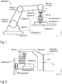
- a robot-assisted grinding device comprises a manipulator 1 (for example an industrial robot) and a grinding machine 10 with a rotating grinding wheel 11, the grinding machine 10 being coupled to the tool center point (TCP) of the manipulator 1 via a linear actuator 20.
- the manipulator can be constructed from four segments 2a, 2b, 2c and 2d, which are each connected via joints 3a, 3b and 3c.
- the last segment 2d is usually rigidly connected to a foundation B (which, however, does not necessarily have to be the case).
- the joint 3c connects the segments 2d and 2c.
- the joint 3c can be biaxial and allow the segment 2c to be rotated about a horizontal axis of rotation (elevation angle) and a vertical axis of rotation (azimuth angle).
- the joint 3b connects the segments 2b and 2c and enables a pivoting movement of the segment 2b relative to the position of the segment 2c.
- the hinge 3a connects the segments 2a and 2b.
- the joint 3a can be biaxial and therefore (similar to the joint 3c) enable a pivoting movement in two directions.
- the TCP has a fixed relative position to segment 2a, which usually also comprises a swivel joint (not shown) that enables a rotary movement about a longitudinal axis A of segment 2a (in Fig.
- Each axis of a joint is assigned an actuator which can cause a rotary movement about the respective joint axis.
- the actuators in the joints are controlled by a robot controller 4 in accordance with a robot program.
- the TCP can be positioned anywhere (within certain limits) (with any orientation of the axis A).
- the manipulator 1 is usually position-controlled, ie the robot controller can determine the pose (position and orientation) of the TCP and move it along a predefined trajectory. Industrial robots and the position control of the TCP are known per se and are therefore not explained further here. If the actuator 20 abuts an end stop, the pose of the TCP also defines the pose of the grinding tool. As already mentioned at the beginning, the actuator 20 serves to set the contact force (process force) between the tool (grinding wheel 11) and workpiece W to a desired value during the grinding process.
- process force process force
- a direct control of the process force by the manipulator 1 is usually too imprecise for grinding applications, since the high inertia of the segments 2a-2c of the manipulator 1 means that compensation of Force peaks (eg when placing the grinding tool on the workpiece 40) are practically not possible with conventional manipulators.
- the robot controller is designed to regulate the pose (position and orientation) of the TCP, while regulating the contact force (see also Fig. 2 , Contact force F K ) can only be produced by the actuator 20 (but not absolutely necessary), which is coupled between the grinding machine 10 and the manipulator 1.
- the contact force F K between the tool (grinding wheel 11) and workpiece W can be set during the grinding process with the aid of the (linear) actuator 20 and a force control unit (which can be implemented, for example, in the controller 4) such that the contact force F K between the grinding tool and workpiece W corresponds to a specifiable setpoint.
- the contact force is a reaction to the actuator force F A with which the linear actuator 20 presses on the workpiece surface. If there is no contact between workpiece 40 and tool, actuator 20 moves against an end stop (in.) Due to the lack of contact force F K Fig. 1 not shown or integrated in the actuator 20).
- the position control of the manipulator 1 (which can also be implemented in the controller 4) can work completely independently of the force control of the actuator 20.
- the actuator 20 is not responsible for the positioning of the grinding machine 10, but only for setting and maintaining the desired contact force during the grinding process and for detecting contact between the tool (grinding machine 10 with grinding wheel 11) and workpiece W.
- a contact can be recognized, for example , if the deflection of the actuator 20 starting from the end stop is none, or the change in the deflection of the actuator 20 becomes negative.
- the actuator can be a pneumatic actuator and can have, for example, a double-acting pneumatic cylinder.
- pneumatic actuators can also be used, such as bellows cylinders and air muscles.
- electric direct drives can also be considered.
- the force control can be implemented in a manner known per se with the aid of a control valve, a controller (implemented in the control 4) and a compressed air store.
- the concrete implementation is not important for the further explanation and is therefore not described in more detail.
- actuator 20 is not needed and can be omitted. In this case, the robot / manipulator 1 can regulate the process force directly.
- FIG. 2 The example shown is between the actuator 20 and the outermost segment 2a of the manipulator 1 (see also Fig. 1 )
- a bracket 21 is arranged, which has approximately an L-shape.
- the purpose of the holder 21 is that the linear actuator 20 does not have to be mounted on the manipulator 1 coaxially to the axis A of the segment 2a (as in FIG Fig. 1 shown), but can be tilted by an angle of, for example, 90 °, so that the axis of rotation R of the grinding machine is essentially parallel to the axis A.
- the holder can also be omitted (actuator 20 is then mounted directly on the manipulator 1) or a holder can be used which has an angle other than 90 °.
- the location of the local coordinate system of the grinding machine is also shown.
- the axis of rotation R of the grinding machine is equal to the z-axis, and the linear actuator 20 acts along the x-axis.
- the tool for example the grinding wheel 11
- the drive for example the motor of the grinding machine 10
- the tool is connected to a first coupling part of the shaft coupling 30 and the drive shaft of the motor is connected to a second coupling part of the shaft coupling 30.
- the first coupling part can be regarded as a special shaft stub on which the tool (grinding wheel 11) is mounted.
- a robot can automatically change the tool, whereby the assembly consisting of tool and the first coupling part is always changed together.
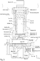
- Fig. 3 shows an exemplary implementation of a shaft coupling 30 (in a disengaged state), which can be used for an automatic, robot-assisted changing of grinding wheels.
- the shaft coupling has a first coupling part 310 and a second coupling part 350.
- the first coupling part 310 is connected to a grinding wheel 11, for example by means of a screw connection.
- a grinding wheel 11 is plugged onto one end of a shaft 330 and is fastened by means of a nut (not shown) which is attached to an Thread 332 provided shaft end is screwed, fixed, so that the grinding wheel 11 is clamped between the nut and a shaft shoulder 331 of the shaft 330.
- the second coupling part 350 has a hub 370, in which the drive shaft of the grinding machine 10 (in Fig. 3 not shown) and can be attached in a conventional manner via a key inserted into the groove 359.
- the two coupling parts 310 and 350 can be connected by means of a conical seat (outer cone 322 on the first coupling part 310 and inner cone 362 on the second coupling part 350). How the two coupling parts 310 and 350 can engage and be fixed to one another is described below with reference to FIG Fig. 4-7 explained in more detail. First, the structure of the first coupling part 310 is discussed in more detail.
- the first coupling part can be seen as a type of telescopic shaft, which is constructed, among other things, from the shaft 330 (to which the grinding wheel 11 is fixed) and a hollow shaft 320, the shaft 330 and the hollow shaft 320 being axially displaceable relative to one another (along the axis of rotation R) ,
- the hollow shaft 320 can be moved relative to the shaft 330 between two end positions.
- a sleeve 335 is arranged coaxially to the shaft 330, the sleeve 335 and the shaft 330 being rigidly connected to one another, for example via a screw connection 333 which connects a shaft section 331 of the shaft 330 to the sleeve 335.
- the outer and inner diameters of the hollow shaft 320 are dimensioned such that the hollow shaft 320 can slide between the shaft 330 and the sleeve 320 (in the axial direction).
- the inner diameter of the sleeve 335 and the outer diameter of the hollow shaft 320 can form a clearance fit .
- the inner diameter of the hollow shaft 320 and the outer diameter D 1 of the shaft 330 can also form a clearance fit.
- a key 336 which is inserted into a groove 337 in the shaft 330, prevents rotation between the hollow shaft 320 and the shaft 330.
- the hollow shaft 320 is displaceable relative to the shaft 330, a first end position of the hollow shaft 320 being formed by a shaft shoulder 338 of the shaft 330 and a second end position of the hollow shaft 320 being formed by an end face of the sleeve 335, which serves as a stop 340.
- the hollow shaft 320 is inserted as far as possible into the sleeve 335, and a shaft shoulder 323 of the hollow shaft 320 bears against the stop 340.
- the hollow shaft 320 protrudes out of the sleeve 335 at most and a shaft shoulder in the interior of the hollow shaft lies against a shaft shoulder 338 of the shaft 330.
- a spring 334 is arranged so that the Spring force pushes the hollow shaft 320 out of the sleeve 335 and presses in the axial direction against the shaft shoulder 338.
- a shaft section at the lower end of the shaft 330 has a diameter D 2 , which can be slightly smaller than the diameter D 1 .
- a cone 341 is provided on the lower end face of the shaft 330, which has a maximum diameter D 3 that is larger than the diameter D 2 , so that a shaft shoulder 339 is formed on the rear side of the cone 341.
- This shaft shoulder 339 serves to axially fix the first coupling part 310 to the second coupling part 350 (cf., for example Fig. 7 )
- the cone 341 is created, for example, by chamfering the peripheral edge at one end of the shaft 330. The chamfer forms the cone 341 mentioned.
- the second coupling part 350 can have a two-part housing (upper part 361, lower part 351), which can, for example, be fixed to one another (for example by means of screws).
- the upper part 361 of the housing has a central inner cone 362 (ie a conical hub) which, together with the corresponding outer cone 322 (on the hollow shaft 320) of the first coupling part 310, can form a conical seat (see for example Fig. 7 ).
- the inner cone 362 runs through the entire upper part 361 and is rotationally symmetrical with respect to the axis of rotation R.
- a radially (transversely to the axis of rotation R and relative to the housing of the second coupling part 350) displaceable securing element 352 is arranged, which by means of a spring 354 is pressed against an end stop in the lower part 351 of the housing.
- the spring 354 is arranged in a radial bore in the lower part 351 of the housing, which is closed with a screw 353. The spring force of the spring 354 thus acts between the securing element 352 and the screw 353.
- the lower part 351 of the housing has a central hole which forms a hub 370 for a motor shaft of the grinding machine 10 (cf. Fig. 2 ).
- the hub 370 can form a groove 359 for receiving a feather key (not shown).
- any other shaft-hub connection can be used for mounting the second coupling part 350 on the motor shaft of the grinding machine 10.
- the securing element has a central opening 355 below the conical hub (inner cone 362), through which the axis of rotation R extends.
- the upper edge of the opening 355 is chamfered so that the chamfer forms a small inner cone 356.
- the lower edge 357 of the opening 355 lies against the shaft shoulder 339 of the shaft 330 of the first coupling part 310 in order to fix the two coupling parts 310, 350 to one another (cf. Fig. 7 ).
- the central opening 355 in the securing element 352 is shown in the illustration Fig. 3 slightly eccentric with respect to the axis of rotation R.
- the two coupling parts 310 and 350 of the shaft coupling Fig. 3 shown in several (intermediate) positions during a coupling process.
- the first coupling part 310 together with a grinding wheel 11 mounted thereon lies on a base plate (cf. Fig. 10 ), and the second coupling part 350 is pressed by the robot onto the first coupling part 310 from above (in this case, the position of the shaft coupling is exactly reversed ( upside down ) as in FIG Fig. 3 ) Shown.
- the first coupling part 310 together with a grinding wheel 11 mounted thereon can also be arranged hanging on a base plate, and one and the second coupling part 350 is pressed onto the first coupling part 310 from below by the robot (in this case, the position of the shaft coupling is the same as in FIG Fig. 3 ) Shown.
- An inclined position of the shaft coupling when engaging and disengaging is also possible.
- Fig. 4 represents a state in which the second coupling part 350 is already partially plugged onto the first coupling part 310 along the axis of rotation R (in the z direction).
- the conical shaft cut 321 (outer cone 322) of the hollow shaft 320 of the first coupling part 310 is inserted into the conical opening (inner cone 362) of the upper part 361 of the housing of the second coupling part 350.
- the chamfered end (cone 341) of the shaft 330 of the first coupling part 310 touches the (eg chamfered, chamfered) edge (inner cone 356) of the central opening 355 of the securing element 352.
- the chamfers 341, 456 can slide on one another during that Securing element 352 is moved transversely to the axis of rotation.
- Fig. 5 represents a state in which the second coupling part 350 is completely plugged onto the first coupling part 310 along the axis of rotation R (in the z direction).
- the conical shaft cut 321 (outer cone 322) of the hollow shaft 320 of the first coupling part 310 and the conical hub (inner cone 362) of the upper part 361 of the housing of the second coupling part 350 form a conical seat (in Fig. 5 labeled with 322/362).
- the situation shown is the securing element 352 compared to that in FIG Fig. 4 situation shown by a shift d to the right (in the direction of the x-axis).
- This shifting of the securing element 352 is supported by the fact that the outer cone 341 (or the chamfer) on the end piece of the shaft 330 and the inner cone 356 on the edge of the opening 355 in the securing element 352 are matched to one another, as a result of which the conical surfaces can slide better on one another.
- the conical shape instead of the conical shape, another oblique or curved shape is also possible. It is also sufficient if only one of the two parts (shaft 330, securing element 352) is conical, oblique or curved at the contact point.
- the two coupling parts 310, 350 are frictionally connected via the conical seat 322/362.
- the conical seat is preloaded in the axial direction (z direction) with the spring force k F ⁇ ⁇ z.
- the securing element 352 is displaced against the force of the spring 354 until the securing element 352 no longer engages on the shaft shoulder 339 of the shaft 330 and consequently the spring 334 Shaft 330 can push back into the starting position (shaft shoulder 338 lies against a shoulder of the hollow shaft 320).
- Figure 8 is a detailed view of the locking element 352 in the engaged state on the shaft shoulder 339 of the shaft 330.
- the edge 357 of the opening 355 of the locking element 352 bears against the shaft shoulder 339 and thereby locks a snap back of the shaft 330 due to the spring force of the spring 334 (cf. Fig. 7 ).
- the elongated holes provided in the securing element 352 only serve to guide the securing element transversely to the axis of rotation R (transversely to the z direction).
- the manipulator can move the grinding tool to a defined storage position.
- a stop 520 is arranged in the vicinity and in a defined position relative to the storage position. For example, by rotating the shaft coupling around the axis of rotation R of the shaft 330, the robot can position the shaft coupling such that the stop 520 fixes the securing element 352 against the force of the spring 354 (see Fig. 7 , in Fig. 8 not shown) presses into the second coupling part 350 and releases the latching connection between the securing element 352 and the shaft shoulder 339 of the shaft 330.
- the stop 520 can also be spring-mounted, the spring stiffness of the stop being greater than the spring stiffness of the spring 354.
- Figure 9 shows an alternative embodiment of the shaft coupling, in which the spring 334, which provides the spring force for the prestressing of the conical seat, does not look like in the example Fig. 7 is arranged in the first coupling part 310, but in the second coupling part 350.
- the function is essentially the same as in the previous example Fig. 3-7 ,
- the first coupling part 310 can be made simpler (because the spring is omitted).
- the first coupling part 310 can be a rigid component.
- the spring 334 is arranged between the upper part 361 and the lower part 351 of the housing of the second coupling part 350.
- the lower part 351 When inserting of the first coupling part 310 into the second coupling part 350, the lower part 351 is pressed towards the upper part 361 against the spring force of one or more springs 334 ′ until the securing element engages on a shaft shoulder of the shaft 330 of the first coupling part, whereby the two coupling parts 310 and 350 are connected to one another be connected and the conical seat is biased by the spring force.
- the shaft coupling is released in the same way as in the previous example (see e.g. Fig. 8 ).
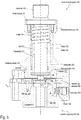
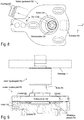
- Figure 10 illustrates an example of a changing station 50 which is suitable for automatic, robot-assisted changing of tools (for example grinding wheels 11 including the first coupling part 310).
- Figure 11 shows a detail of the changing station 50 with an inserted shaft coupling 30.
- a robot / manipulator eg in a robot cell
- several similar changing stations eg next to each other
- different tools can be made available for the (processing) process carried out by the robot / manipulator;
- By simply changing the shaft (with the tool attached to it) several (different) work steps can be carried out at one workstation with a robot / manipulator.
- the changing station comprises a base 501, which is generally stationary and has a defined position, which is known to the robot controller.
- a support plate 510 is mounted on the base 501.
- the support plate 510 is displaceably mounted on the base 501 by means of set screws 516, which are screwed to the base 501 and are guided through corresponding holes in the support plate 510 (against the z direction).
- the support plate 510 is pressed against the base 501 by means of springs 515, which act between the support plate 510 and nuts screwed onto the threaded pins 516.
- the support plate 510 can therefore be raised against the force of the springs 515 from the base 501.
- the support plate 510 is rigidly connected to the base 501 or the base 501 also serves as the support plate 510.
- the cover 505 is also optional.
- a recess 511 is provided in the support plate 510, into which the robot (see Fig. 1 , Manipulator 10) can insert the shaft coupling 30 laterally.
- the shaft coupling is in the y direction (see arrow in Fig. 10 ) inserted into the recess 511.
- this can be a have a circular contour.
- the upper edge of the recess 511 can be chamfered.
- the chamfer 512 forms a cone on which the first coupling part 310 of the shaft coupling 30 can rest. More specifically, the cone 345 of the hollow shaft 320 of the first coupling part 310 (see e.g. Fig.
- At least one stop 520 and a proximity switch 521 are arranged on the support plate 510.
- the function of the stop and the proximity switch 521 is shown in FIG Fig. 11 clear.
- FIG. 11 A situation is shown in which the shaft coupling 30 has just been rotated such that the outer end of the securing element 352 lies against the stop 520. The rotation of the shaft coupling 30 against the stop has been made with reference to FIG Fig. 8 explained.
- the stop 520 presses the securing element 352 into the second coupling part 350 and releases the latching connection with the shaft 330.
- the tool 11 with the first coupling part 310 remains in the changing station 50 and can be used later (for example manually). to be replaced by a new tool 11.
- the robot moves the grinding machine 10 to a changing station 50 with an inserted new grinding wheel 11 (including the first coupling part 310) such that the axis of rotation R of the motor of the grinding wheel 11 is coaxial with the axis of rotation of the tool to be coupled (cf. , Fig. 3 ).
- the process of pairing has already been made with reference to Fig. 3-7 described in detail.
- the securing element 352 moves away from the proximity switch 521 by a distance d (cf. Fig. 4-5 ) and then back to the starting position (cf. Fig. 6-7 ).
- This movement (forwards, backwards and forwards again) of the securing element 352 can be detected by the proximity switch 521 and in this way a proper coupling of the two coupling parts 310, 350 are monitored.
- Proximity switches 521 usually detect the presence of the securing element 352 via a mechanical contact.
- non-contact (eg inductive, capacitive or optical) proximity switches can also be used, which are also generally referred to as proximity sensors .
- a safety feature is the resilient mounting of the support plate 510 on the base 501. If the release of the shaft coupling 30 fails (for whatever reason), then the robot, when attempting to lift the grinding machine 11 with the second coupling part 350, will at the same time also Raise the support plate 510 against the spring force of the springs 515, since the non-disengaged first coupling part 310 takes the support plate with it when the coupling is inserted into the recess 511. This lifting of the support plate 510 can be detected by means of a sensor.
- a suitable sensor for this is e.g. a contact switch, a proximity sensor, a light sensor (which is covered by the platen when it is not raised), etc.
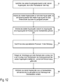
- FIG. 12 is a flowchart illustrating the sequence of a shaft change process, that is, the engagement of a shaft coupling such as a Fig. 3-7 shown and the release of the shaft coupling such as in Fig. 11 shown.
- a shaft of the first coupling part 310, see Fig. 3
- first coupling part 310 lies in recess 511 of the exchange station 50.
- a manipulator 1 cf. Fig. 1
- a machine tool with the second coupling part is moved towards the changing station so that the two coupling parts are aligned essentially coaxially (see Fig. 12 , Step S1).
- the manipulator can then press the two coupling parts against each other until a securing element of the second coupling part engages on a shaft shoulder of the first coupling part (see Fig. 12 , Step S2, cf. also Fig. 6-7 , Securing element 352 engages on shaft shoulder 339).
- the manipulator can then lift the second coupling part (and thus the entire shaft coupling including tools) and remove it from the exchange station ( Fig. 12 , Step S3).
- the second coupling part is moved out of the recess 511.
- the coupled tool can then be used for the automated machining of a workpiece (see Fig. 12 , Step S4).
- the shaft coupling can be reinserted in a changing station (in the same as before or in another), whereby when inserting over one Stop in the exchange station (cf. Fig. 10 , Stop 520) the securing element is actuated, as a result of which the latching connection is released (cf. state before being released in Fig. 7 , State after loosening in Fig. 6 ), please refer Fig. 12 , Step S5. Finally, the manipulator can move the released second coupling part out of the changing station and the first coupling part with the (used) tool remains in the changing station ( Fig. 12 , Step S6).
- the exemplary embodiments of the shaft coupling and the change station described here do not need their own energy supply (for example electrical current or compressed air). Consequently, the shaft coupling does not require any supply lines for electricity, compressed air and the like. Connectors, sliding contacts, etc. can be avoided.
- the exchange station (see Fig. 10 ) does not need its own drive.
- An exemplary embodiment relates to a shaft coupling which has a first coupling part with a shaft and a conical shaft section (cf. for example Fig. 3 ).
- a tool for example a grinding wheel, a drill, etc.
- the shaft coupling has a second coupling part which has a conical hub, into which the conical shaft section of the first coupling part can be inserted to form a conical seat.
- the second coupling part furthermore has a securing element which can be moved transversely to an axis of rotation of the shaft coupling and which is arranged such that it can snap into place on the shaft shoulder of the shaft (cf. Fig. 6 and 7 ).
- At least one spring is arranged in the shaft coupling in such a way that it generates a spring force which, when the securing element is engaged, acts on the conical seat in the axial direction and prestresses it.
- the spring that biases the conical seat can either be in the first coupling part (see Fig. 3 , Spring 334) or in the second coupling part (see Fig. 9 , Spring 334 ') may be provided.
- the first coupling part has a hollow shaft which is axially displaceably mounted on the shaft.
- the conical shaft section is part of the hollow shaft (see Fig. 3 , Shaft section 321 outside on the hollow shaft 320).
- the spring is contained in the first coupling part and arranged so that the hollow shaft is displaced against the spring force of the spring on the shaft when the conical shaft section is inserted into the conical hub (see 4 to 6 ).
- the relative movement between the hollow shaft and the shaft penetrates the shaft shoulder of the shaft into the second coupling part until the securing element can snap into the shaft shoulder and form a latching connection.
- the shaft can have a further shaft shoulder, which forms an end stop for the hollow shaft, the spring force of the spring pressing the hollow shaft against the end stop.
- a feather key can be arranged between the shaft and the hollow shaft so that an axial displacement (relative movement) between the shaft and the hollow shaft is possible, but a rotation between the shaft and the hollow shaft is blocked.
- the spring that prestresses the conical seat can also be arranged in the second coupling part (see Fig. 9 , Spring 334 ').
- the second coupling part comprises a lower part and an upper part which is axially displaceable relative to the lower part.
- the conical hub is arranged in the upper part, and the at least one spring is arranged between the lower part and the upper part in such a way that when the conical shaft section is inserted into the conical hub, the lower part is displaced towards the upper part against the spring force of the spring (see, for example Fig. 9 , Spring 334 'acts between lower part 351 and upper part 361 and prestresses the conical seat).
- the securing element can protrude from the second coupling part. Furthermore, the securing element can have a (central) opening, into which the shaft can be inserted until the securing element can snap into the shaft shoulder of the shaft, the latching connection preventing the shaft from being pulled back out of the opening.
- an edge of the central opening in the securing element is moved behind the shaft shoulder of the shaft (transversely to the axis of rotation of the shaft coupling, cf. 6 to 7 ).
- the spring force prestresses the conical shaft section against the conical hub.
- the edge of the opening in the securing element and a peripheral edge of the shaft can each be chamfered. The chamfer on the edge of the shaft and the chamfer on the edge of the opening can slide against one another when the shaft is inserted into the opening while the securing element is being displaced.
- Another exemplary embodiment relates to a system with a manipulator and a machine tool with a motor shaft for driving a tool.
- the machine tool is coupled to the manipulator and can be positioned by it.
- the system comprises a shaft coupling which can be constructed in accordance with one of the exemplary embodiments described here.
- Another exemplary embodiment relates to a system with a shaft coupling, which can be constructed in accordance with one of the exemplary embodiments described here, and with at least one changing station.
- the exchange station has a support plate with a recess.
- the recess defines a storage position in which the first coupling part of the shaft coupling can be inserted into the recess.
- the conical shaft section of the first coupling part protrudes from the support plate.
- the system can also have a stop arranged on the support plate.
- the system can have a proximity sensor which is arranged such that it can detect a displacement of the securing element during the coupling of the two coupling parts.
- the support plate can be resiliently mounted on a base (see e.g. Fig. 10 , Springs 515), which is why the support plate can be raised relative to the base (safety feature).
- a further exemplary embodiment relates to a method according to which a manipulator is used to initially align a second coupling part of a shaft coupling coaxially with a first coupling part of the shaft coupling (see, for example, Fig. 3 ), which is available in a change station (see e.g. Fig. 11 ).
- the second coupling part is then pressed onto the first coupling part until a securing element of the second coupling part engages on a shaft shoulder of the first coupling part and forms a latching connection (see, for example Fig. 6 and 7 , such as Fig. 9 ).
- the first coupling part (with the tool) can also be lifted out of the changing station by lifting the second coupling part.
- the manipulator can be used to carry out an automated (machining) process on a workpiece.
- the shaft coupling is then connected to the Exchange station (or another exchange station) inserted in such a way that the securing element of the second coupling part can be actuated via a stop in the respective exchange station, as a result of which the latching connection is released.
- the second coupling part is removed from the respective changing station by means of the manipulator, while the first coupling part remains in the changing station.
- a conical shaft section of the first coupling part can be inserted into a conical hub of the second coupling part, whereby a conical seat is formed.
- the shaft shoulder of the first coupling part can be pushed into the second coupling part until the securing element engages on the shaft shoulder so that the spring force prestresses the conical seat in the engaged state.
- the securing element is moved transversely to an axis of rotation of the shaft coupling, and this movement can be detected by means of a proximity sensor.
- the shaft shoulder can be pressed away from the securing element using a spring (see e.g. Fig.
- the shaft coupling After inserting the shaft coupling into the changing station (or another changing station), the shaft coupling can be rotated about its axis of rotation until the end of the securing element protruding from the second coupling part lies against the stop of the changing station.
Landscapes
- Engineering & Computer Science (AREA)
- Robotics (AREA)
- Mechanical Engineering (AREA)
- Manipulator (AREA)
- Finish Polishing, Edge Sharpening, And Grinding By Specific Grinding Devices (AREA)
- Constituent Portions Of Griding Lathes, Driving, Sensing And Control (AREA)
- Jigs For Machine Tools (AREA)
- Gripping On Spindles (AREA)
Description
Die vorliegende Erfindung betrifft ein Verfahren und ein System zum automatischen, robotergestützten Wechseln von Wellen. An den zu wechselnden Wellen können beispielsweise Schleifscheiben für eine robotergestützte Schleifvorrichtung oder auch andere rotierbare Werkzeuge montiert sein.The present invention relates to a method and a system for automatic, robot-assisted changing of shafts. For example, grinding wheels for a robot-assisted grinding device or other rotatable tools can be mounted on the shafts to be changed.
Bei robotergestützten Schleifvorrichtungen wird ein Schleifwerkzeug (z.B. eine elektrisch betriebene Schleifmaschine mit rotierender Schleifscheibe) von einem Manipulator, beispielsweise einem Industrieroboter, geführt. Dabei kann das Schleifwerkzeug auf unterschiedliche Weise mit dem sogenannten TCP (Tool Center Point) des Manipulators gekoppelt sein, sodass der Manipulator Position und Orientierung des Werkzeugs praktisch beliebig einstellen kann. Industrieroboter sind üblicherweise positionsgeregelt, was eine präzise Bewegung des TCP entlang einer gewünschten Trajektorie ermöglicht. Um beim robotergestützten Schleifen ein gutes Ergebnis zu erzielen ist in vielen Anwendungen eine Regelung der Prozesskraft (Schleifkraft) nötig, was mit herkömmlichen Industrierobotern oft nur schwer mit hinreichender Genauigkeit zu realisieren ist. Die großen und schweren Armsegmente eines Industrieroboters besitzen eine zu große Massenträgheit, als dass ein Regler (closed-loop controller) rasch genug auf Schwankungen der Prozesskraft reagieren könnte. Um dieses Problem zu lösen, kann zwischen TCP des Manipulators und dem Schleifwerkzeug ein im Vergleich zum Industrieroboter (vergleichsweise kleiner) Linearaktor angeordnet sein, der den TCP des Manipulators mit dem Schleifwerkzeug koppelt. Der Linearaktor regelt während des Schleifens lediglich die Prozesskraft (also die Anpresskraft zwischen Werkzeug und Werkstück) während der Manipulator das Schleifwerkzeug samt Linearaktor positionsgeregelt entlang einer vorgebbaren Trajektorie bewegt. Die Druckschrift
Auch bei robotergestützten Schleifvorrichtungen werden verschlissene Schleifscheiben häufig noch manuell gewechselt. Obwohl einige Konzepte für robotergestützte Wechselstationen zum Wechseln von Schleifscheiben existieren, sind bekannte Lösungen vergleichsweise komplex, aufwändig zu realisieren und daher teuer.Even with robot-assisted grinding devices, worn grinding wheels are often still changed manually. Although there are some concepts for robot-assisted changing stations for changing grinding wheels, known solutions are comparatively complex, complex to implement and therefore expensive.
Die Erfinder haben sich die Aufgabe gestellt, ein System und ein Verfahren zur Verfügung zu stellen, das aus einfache Weise ein automatisches, robotergestütztes Wechseln von rotierenden Werkzeugen wie z.B. Schleifscheiben ermöglicht.The inventors have set themselves the task of providing a system and a method which can easily and automatically change robot tools, such as rotating tools, e.g. Allows grinding wheels.
Die oben genannte Aufgabe wird durch die Vorrichtung gemäß Anspruch 1 gelöst. Unterschiedliche Ausführungsformen und Weiterentwicklungen sind Gegenstand der abhängigen Ansprüche.The above object is achieved by the device according to
Es wird hier ein System für die robotergestützte Bearbeitung von Werkstücken beschrieben. Gemäß einem Ausführungsbeispiel weist das System eine Werkzeugmaschine mit einer Motorwelle zum Antrieb eines Werkzeugs, einen Linearaktor zum Koppeln der Werkzeugmaschine mit einem Manipulator sowie eine Wellenkupplung zum Koppeln der Motorwelle der Werkzeugmaschine mit dem Werkzeug auf. Ein erster Kupplungsteil der Wellenkupplung weist einer Welle und einem konischen Wellenabschnitt auf, wobei an einem ersten Ende der Welle das Werkzeug fixierbar ist und an einem zweiten Ende der Welle eine Wellenschulter angeordnet ist. Ein zweiter Kupplungsteil der Wellenkupplung ist mit der Motorwelle der Werkzeugmaschine starr verbunden ist und weist eine konische Nabe auf, in die der konische Wellenabschnitt (des ersten Kupplungsteils) zur Bildung eines Kegelsitzes einführbar ist. Der zweite Kupplungsteil weist weiter ein quer zu einer Rotationsachse der Wellenkupplung verschiebbares Sicherungselement auf, welches so angeordnet ist, dass es an der Wellenschulter der Welle einrasten kann. Die Wellenkupplung beinhaltet mindestens eine Feder, die so angeordnet ist, dass sie eine Federkraft erzeugt, welche bei eingerastetem Sicherungselement in axialer Richtung auf den Kegelsitz wirkt und diesen vorspannt.A system for robot-assisted machining of workpieces is described here. According to one exemplary embodiment, the system has a machine tool with a motor shaft for driving a tool, a linear actuator for coupling the machine tool with a manipulator and a shaft coupling for coupling the motor shaft of the machine tool with the tool. A first coupling part of the shaft coupling has a shaft and a conical shaft section, the tool being fixable at a first end of the shaft and a shaft shoulder being arranged at a second end of the shaft. A second coupling part of the shaft coupling is rigidly connected to the motor shaft of the machine tool and has a conical hub into which the conical shaft section (of the first coupling part) can be inserted to form a conical seat. The second coupling part also has a securing element which can be displaced transversely to an axis of rotation of the shaft coupling and which is arranged such that it can snap into place on the shaft shoulder of the shaft. The shaft coupling contains at least one spring which is arranged in such a way that it generates a spring force which, when the securing element is engaged, acts on the conical seat in the axial direction and prestresses it.
Es wird im Folgenden eine Wellenkupplung beschrieben. Gemäß einem Ausführungsbeispiel umfasst die Wellenkupplung einen ersten Kupplungsteil mit einer Welle und einem konischen Wellenabschnitt. An einem ersten Ende der Welle ist ein Werkzeug (z.B. eine Schleifscheibe, ein Bohrer, etc.) fixierbar, und an einem zweiten Ende der Welle ist eine Wellenschulter angeordnet. Die Wellenkupplung umfasst des Weiteren einen zweiten Kupplungsteil, der eine konische Nabe aufweist, in die der konische Wellenabschnitt des ersten Kupplungsteils zur Bildung eines Kegelsitzes einführbar ist. Der zweite Kupplungsteil weist des Weiteren ein quer zu einer Rotationsachse der Wellenkupplung verschiebbares Sicherungselement aufweist, das so angeordnet ist, dass es an der Wellenschulter der Welle einrasten kann. Mindestens eine Feder ist so in der Wellenkupplung angeordnet, dass sie eine Federkraft erzeugt, welche bei eingerastetem Sicherungselement in axialer Richtung auf den Kegelsitz wirkt und diesen vorspannt.A shaft coupling is described below. According to one exemplary embodiment, the shaft coupling comprises a first coupling part with a shaft and a conical shaft section. At a first end of the shaft is a tool (e.g. a grinding wheel, a drill, etc.) can be fixed, and a shaft shoulder is arranged at a second end of the shaft. The shaft coupling further comprises a second coupling part, which has a conical hub into which the conical shaft section of the first coupling part can be inserted to form a conical seat. The second coupling part furthermore has a securing element which can be moved transversely to an axis of rotation of the shaft coupling and which is arranged such that it can snap into place on the shaft shoulder of the shaft. At least one spring is arranged in the shaft coupling in such a way that it generates a spring force which, when the securing element is engaged, acts on the conical seat in the axial direction and prestresses it.
Ein weiteres Ausführungsbeispiel betrifft ein Verfahren, gemäß dem mittels eines Manipulators zunächst ein zweites Kupplungsteils einer Wellenkupplung, der eine konische Nabe aufweist, koaxial zu einem ersten Kupplungsteil der Wellenkupplung ausgerichtet wird, der einen konischen Wellenabschnitt aufweist und in einer Wechselstation bereit liegt. Anschließend wird das zweite Kupplungsteil auf den ersten Kupplungsteil gedrückt, bis ein Sicherungselement des zweiten Kupplungsteils an einer Wellenschulter des ersten Kupplungsteils einrastet und eine Rastverbindung bildet. Nach dem Einkuppeln kann durch das Anheben des zweiten Kupplungsteils auch der erste Kupplungsteil aus der Wechselstation gehoben werden. Mittels des an dem ersten Kupplungsteil montierten Werkzeugs kann mit Hilfe des Manipulators automatisiert ein (Bearbeitungs-) Prozess an einem Werkstück durchgeführt werden. Im Anschluss wird die Wellenkupplung in die Wechselstation (oder eine andere Wechselstation) derart eingelegt, dass über einen Anschlag in der jeweiligen Wechselstation das Sicherungselement des zweiten Kupplungsteils betätigt werden kann, wodurch die Rastverbindung gelöst wird. Nach dem Auskuppeln wird das zweite Kupplungsteil aus der jeweiligen Wechselstation mittels des Manipulators entfernt, während der erste Kupplungsteil in der Wechselstation verbleibt.A further exemplary embodiment relates to a method according to which a manipulator is used to initially align a second coupling part of a shaft coupling, which has a conical hub, coaxially with a first coupling part of the shaft coupling, which has a conical shaft section and is available in a changing station. The second coupling part is then pressed onto the first coupling part until a securing element of the second coupling part engages on a shaft shoulder of the first coupling part and forms a latching connection. After coupling, the first coupling part can also be lifted out of the changing station by lifting the second coupling part. Using the tool mounted on the first coupling part, the manipulator can be used to carry out an automated (machining) process on a workpiece. The shaft coupling is then inserted into the changing station (or another changing station) in such a way that the securing element of the second coupling part can be actuated via a stop in the respective changing station, as a result of which the latching connection is released. After disengaging, the second coupling part is removed from the respective changing station by means of the manipulator, while the first coupling part remains in the changing station.
Die Erfindung wird nachfolgend anhand von den in den Abbildungen dargestellten Beispielen näher erläutert. Die Darstellungen sind nicht zwangsläufig maßstabsgetreu und die Erfindung beschränkt sich nicht nur auf die dargestellten Aspekte. Vielmehr wird Wert darauf gelegt, die der Erfindung zugrunde liegenden Prinzipien darzustellen. In den Abbildungen zeigt:
-
Figur 1 -
Figur 2 -
Figuren 3 zeigt eine exemplarische Implementierung einer Wellenkupplung aus dem Beispiel ausFig. 2 in einem ausgekuppelten Zustand. -
Figuren 4-7 zeigen die Wellenkupplung gemäßFig. 3 in unterschiedlichen Positionen während des Einkuppelns. -
Figur 8 zeigt ein Sicherungselement der Wellenkupplung ausFig. 3 in einer Draufsicht. -
Figur 9 zeigt eine weitere exemplarische Implementierung der Wellen aus dem Beispiel ausFig. 2 in einem eingekuppelten Zustand. -
Figur 10 -
Figur 11Fig. 10 mit der Wellenkupplung. -
Figur 12 ist ein Flussdiagramm, das den Ablauf eines Wellenwechselvorganges darstellt.
-
Figure 1 schematically shows an example of a robot-assisted grinding device in which a grinding machine is positioned by means of a manipulator. -
Figure 2 shows schematically the grinding machine, a bracket for mounting the grinding machine on the manipulator and a shaft coupling that couples the grinding wheel to the shaft of the grinding machine. -
Figures 3 shows an exemplary implementation of a shaft coupling from the exampleFig. 2 in a disengaged state. -
Figures 4-7 show the shaft coupling according toFig. 3 in different positions during engagement. -
Figure 8 shows a securing element of the shaft couplingFig. 3 in a top view. -
Figure 9 shows another exemplary implementation of the waves from the exampleFig. 2 in an engaged state. -
Figure 10 shows an example of a changing station with which a robot can change a tool that is connected to the machine via one of the shaft couplings described here. -
Figure 11 shows a detail of the exchange stationFig. 10 with the shaft coupling. -
Figure 12 is a flowchart illustrating the flow of a shaft changing process.
Ausführungsbeispiele der Erfindung werden anhand einer robotergestützten Schleifvorrichtung beschrieben. Die Beschreibung ist jedoch nicht auf robotergestütztes Schleifen beschränkt. Die hier beschriebenen Ausführungsbeispiele betreffen allgemein eine Wellenkupplung und ein System zum Wechseln von Wellen, an denen ein beliebiges rotierendes Werkzeug montiert sein kann wie z.B. eine Schleifscheibe, eine Polierscheibe ein Bohrer, ein Fräser, ein Schraubendreher, etc. Die in dieser Beschreibung erwähnte Schleifmaschine steht exemplarisch für eine beliebige Werkzeugmaschine, und die Schleifscheibe steht exemplarisch für ein beliebiges von der Werkzeugmaschine angetriebenes rotierendes Werkzeug.Exemplary embodiments of the invention are described using a robot-assisted grinding device. However, the description is not limited to robot-assisted grinding. The exemplary embodiments described here generally relate to a shaft coupling and a system for changing shafts, on which any rotating tool can be mounted, such as a grinding wheel, a polishing wheel, a drill, a milling cutter, a screwdriver, etc. The grinding machine mentioned in this description stands exemplarily for any machine tool, and the grinding wheel exemplarily stands for any rotating tool driven by the machine tool.
Bevor verschiedene Ausführungsbeispiele im Detail erläutert werden, wird zunächst ein allgemeines Beispiel einer robotergestützten Schleifvorrichtung beschrieben. Diese umfasst einen Manipulator 1 (beispielsweise einen Industrieroboter) und eine Schleifmaschine 10 mit rotierender Schleifscheibe 11, wobei die Schleifmaschine 10 mit dem Tool-Center-Point (TCP) des Manipulators 1 über einen Linearaktor 20 gekoppelt ist. Im Falle eines Industrieroboters mit sechs Freiheitsgraden kann der Manipulator aus vier Segmenten 2a, 2b, 2c und 2d aufgebaut sein, die jeweils über Gelenke 3a, 3b und 3c verbunden sind. Das letzte Segment 2d ist dabei meist starr mit einem Fundament B verbunden (was jedoch nicht zwangsläufig der Fall sein muss). Das Gelenk 3c verbindet die Segmente 2d und 2c. Das Gelenk 3c kann zweiachsig sein und eine Drehung des Segments 2c um eine horizontale Drehachse (Elevationswinkel) und eine vertikale Drehachse (Azimutwinkel) ermöglichen. Das Gelenk 3b verbindet die Segmente 2b und 2c und ermöglicht eine Schwenkbewegung des Segments 2b relativ zur Lage des Segments 2c. Das Gelenk 3a verbindet die Segmente 2a und 2b. Das Gelenk 3a kann zweiachsig sein und daher (ähnlich wie das Gelenk 3c) eine Schwenkbewegung in zwei Richtungen ermöglichen. Der TCP hat eine feste Relativposition zum Segment 2a, wobei dieses üblicherweise noch ein Drehgelenk (nicht dargestellt) umfasst, dass eine Drehbewegung um eine Längsachse A des Segments 2a ermöglicht (in
Der Manipulator 1 ist üblicherweise positionsgeregelt, d.h. die Robotersteuerung kann die Pose (Position und Orientierung) des TCP festlegen und diesen entlang einer vordefinierten Trajektorie bewegen. Industrieroboter und die Positionsregelung des TCP ist an sich bekannt und wird daher hier nicht weiter erläutert. Wenn der Aktor 20 an einem Endanschlag anliegt, ist mit der Pose des TCP auch die Pose des Schleifwerkzeugs definiert. Wie eingangs bereits erwähnt, dient der Aktor 20 dazu, während des Schleifprozesses die Kontaktkraft (Prozesskraft) zwischen Werkzeug (Schleifscheibe 11) und Werkstück W auf einen gewünschten Wert einzustellen. Eine direkte Regelung der Prozesskraft durch den Manipulator 1 ist für Schleifanwendungen üblicherweise zu ungenau, da durch die hohe Massenträgheit der Segmente 2a-2c des Manipulators 1 eine schnelle Kompensation von Kraftspitzen (z.B. beim Aufsetzen des Schleifwerkzeugs auf das Werkstück 40) mit herkömmlichen Manipulatoren praktisch nicht möglich ist. Aus diesem Grund ist die Robotersteuerung dazu ausgebildet, die Pose (Position und Orientierung) des TCP zu regeln, während die Regelung der Kontaktkraft (siehe auch
Wie bereits erwähnt kann während des Schleifprozesses die Kontaktkraft FK zwischen Werkzeug (Schleifscheibe 11) und Werkstück W mit Hilfe des (Linear-) Aktors 20 und einer Kraftregeleinheit (die beispielsweise in der Steuerung 4 implementiert sein kann) so eingestellt werden, dass die Kontaktkraft FK zwischen Schleifwerkzeug und Werkstück W einem vorgebbaren Sollwert entspricht. Die Kontaktkraft ist dabei eine Reaktion auf die Aktorkraft FA, mit der der Linearaktor 20 auf die Werkstückoberfläche drückt. Bei fehlendem Kontakt zwischen Werkstück 40 und Werkzeug fährt der Aktor 20 aufgrund der fehlenden Kontaktkraft FK gegen einen Endanschlag (in
Der Aktor kann ein pneumatischer Aktor sein und beispielsweise einen doppeltwirkenden Pneumatikzylinder aufweisen. Jedoch sind auch andere pneumatische Aktoren anwendbar wie z.B. Balgzylinder und Luftmuskel. Als Alternative kommen auch elektrische Direktantriebe (getriebelos) in Betracht. Im Falle eines pneumatischen Aktors kann die Kraftregelung in an sich bekannter Weise mit Hilfe eines Regelventils, eines Reglers (implementiert in der Steuerung 4) und eines Druckluftspeichers realisiert werden. Die konkrete Implementierung ist jedoch für die weitere Erläuterung nicht wichtig und wird daher auch nicht detaillierter beschrieben. In manchen Anwendung wird der Aktor 20 nicht benötigt und kann weg gelassen werden. In diesem Fall kann der Roboter/Manipulator 1 die Prozesskraft direkt regeln. Manche Anwendungen kommen auch ohne Kraftregelung aus und der Roboter/Manipulator 1 arbeitet positionsgeregelt. Für die hier beschriebene Wellenkupplung und das Wellenwechselsystem ist die Kraft- und Positionsregelung an sich nicht weiter relevant, sie kann jedoch für den mit dem Werkzeug durchgeführten (Bearbeitungs-) Prozess nützlich sein.The actuator can be a pneumatic actuator and can have, for example, a double-acting pneumatic cylinder. However, other pneumatic actuators can also be used, such as bellows cylinders and air muscles. As an alternative, electric direct drives (gearless) can also be considered. In the case of a pneumatic actuator, the force control can be implemented in a manner known per se with the aid of a control valve, a controller (implemented in the control 4) and a compressed air store. However, the concrete implementation is not important for the further explanation and is therefore not described in more detail. In some applications,
In dem in
Das Werkzeug (z.B. die Schleifscheibe 11) kann mit dem Antrieb (z.B. Motor der Schleifmaschine 10) über eine Wellenkupplung 30 verbunden sein. In diesem Fall ist das Werkzeug mit einem ersten Kupplungsteil der Wellenkupplung 30 und die Antriebswelle des Motors mit einem zweiten Kupplungsteil der Wellenkupplung 30 verbunden. Der erste Kupplungsteil kann als spezieller Wellenstummel betrachtet werden, an dem das Werkzeug (die Schleifscheibe 11) montiert ist. Mit Hilfe einer speziellen Wechselstation (siehe z.B.
Der erste Kupplungsteil kann als eine Art Teleskopwelle gesehen werden, die unter anderem aus der Welle 330 (an der die Schleifscheibe 11 fixiert ist) und einer Hohlwelle 320 aufgebaut ist, wobei Welle 330 und Hohlwelle 320 axial zueinander verschiebbar sind (entlang der Drehachse R). Die Hohlwelle 320 ist dabei relativ zur Welle 330 zwischen zwei Endpositionen verschiebbar. Koaxial zur Welle 330 ist eine Hülse 335 angeordnet, wobei Hülse 335 und Welle 330 starr miteinander verbunden sind, beispielsweise über eine Schraubverbindung 333, die einen Wellenabschnitt 331 der Welle 330 mit der Hülse 335 verbindet. Außen- und Innendurchmesser der Hohlwelle 320 sind so dimensioniert, dass die Hohlwelle 320 zwischen Welle 330 und Hülse 320 (in axialer Richtung) gleiten kann. Der Innendurchmesser der Hülse 335 und der Außendurchmesser der Hohlwelle 320 können eine Spielpassung bilden (clearance fit). Gleichermaßen können Innendurchmesser der Hohlwelle 320 und der Außendurchmesser D1 der Welle 330 ebenso eine Spielpassung bilden. Eine Passfeder 336, welche in eine Nut 337 der Welle 330 eingesetzt ist, verhindert eine Verdrehung zwischen Hohlwelle 320 und Welle 330.The first coupling part can be seen as a type of telescopic shaft, which is constructed, among other things, from the shaft 330 (to which the
Wie erwähnt ist die Hohlwelle 320 relativ zur Welle 330 verschiebbar, wobei eine erste Endposition der Hohlwelle 320 von einer Wellenschulter 338 der Welle 330 und eine zweite Endposition der Hohlwelle 320 von einer Stirnseite der Hülse 335, die als Anschlag 340 dient, gebildet wird. In der zweiten Endposition ist die Hohlwelle 320 so weit wie möglich in die Hülse 335 eingeführt, und eine Wellenschulter 323 der Hohlwelle 320 liegt am Anschlag 340 an. In der ersten Endposition ragt die Hohlwelle 320 maximal aus der Hülse 335 heraus und ein Wellenabsatz im Inneren der Hohlwelle liegt an einer Wellenschulter 338 der Welle 330 an. In der Hülse 335 ist eine Feder 334 so angeordnet, dass die Federkraft die Hohlwelle 320 aus der Hülse 335 herausdrückt und in axialer Richtung gegen die Wellenschulter 338 drückt.As mentioned, the
Ein Wellenabschnitt am unteren Ende der Welle 330 hat einen Durchmesser D2, der etwas kleiner sein kann als der Durchmesser D1. An der unteren Stirnseite der Welle 330 ist ein Konus 341 vorgesehen, der einen maximalen Durchmesser D3 aufweist, der größer ist, als der Durchmesser D2, sodass an der Rückseite des Konus 341 eine Wellenschulter 339 gebildet wird. Diese Wellenschulter 339 dient zur axialen Fixierung des ersten Kupplungsteils 310 an dem zweiten Kupplungsteil 350 (vgl. z.B.
Der zweite Kupplungsteil 350 kann ein zweiteiliges Gehäuse aufweisen (Oberteil 361, Unterteil 351), die beispielsweise fest aneinander fixiert (z.B. mittels Schrauben) sein können. Der Oberteil 361 des Gehäuses weist einen zentralen Innenkonus 362 (d.h. eine konische Nabe), der zusammen mit dem korrespondierenden Außenkonus 322 (an der Hohlwelle 320) des ersten Kupplungsteils 310 einen Kegelsitz bilden kann (siehe z.B.
Das Unterteil 351 des Gehäuses weist ein zentrales Loch auf, das eine Nabe 370 für eine Motorwelle der Schleifmaschine 10 bildet (vgl.
Das Sicherungselement weist unterhalb der konischen Nabe (Innenkonus 362) eine zentrale Öffnung 355 auf, durch die die Drehachse R hindurchverläuft. Die obere Kante der Öffnung 355 ist angefast, sodass die Fase einen kleinen Innenkonus 356 bildet. Die untere Kante 357 der Öffnung 355 liegt im eingekuppelten Zustand an der Wellenschulter 339 der Welle 330 des ersten Kupplungsteils 310 an, um die beiden Kupplungsteile 310, 350 aneinander zu fixieren (vgl. z.B.
In den
In der in
Nachdem das Sicherungselement 352 an der Wellenschulter 339 der Welle 330 eingerastet ist, sind die die beiden Kupplungsteile 310, 350 reibschlüssig über den Kegelsitz 322/362 verbunden. Der Kegelsitz ist in axialer Richtung (z-Richtung) mit der Federkraft kF·Δz vorgespannt. Zum Lösen der Verbindung der beiden Kupplungsteile 310, 350 muss (mit Hilfe des Manipulators, siehe
Um die Verbindung der beiden Kupplungsteile 310 und 350 wieder zu lösen kann der Manipulator das Schleifwerkzeug an eine definierte Ablageposition bewegen. In der Nähe und in definierter Lage relativ zu der Ablageposition ist ein Anschlag 520 angeordnet. Beispielsweise durch eine Drehung der Wellenkupplung um die Drehachse R der Welle 330 kann der Roboter die Wellenkupplung so positionieren, dass der Anschlag 520 das Sicherungselement 352 gegen die Kraft der Feder 354 (siehe
Die Wechselstation umfasst eine Basis 501, welche in der Regel ortsfest ist und eine definierte Position aufweist, welche der Robotersteuerung bekannt ist. An der Basis 501 ist eine Auflageplatte 510 gelagert. Im dargestellten Bespiel ist die Auflageplatte 510 an der Basis 501 mittels Gewindestiften 516, welche mit der Basis 501 verschraubt und durch korrespondierende Löcher in der Auflageplatte 510 hindurchgeführt sind, verschiebbar gelagert (gegen die z-Richtung). Die Auflageplatte 510 wird mittels Federn 515, die zwischen Auflageplatte 510 und auf die Gewindestifte 516 aufgeschraubte Muttern wirken, gegen die Basis 501 gedrückt. Die Auflageplatte 510 kann demnach gegen die Kraft der Federn 515 von der Basis 501 angehoben werden. Der Zweck dieser Lagerung wird weiter unten erläutert. In einem alternativen Ausführungsbeispiel ist die Auflageplatte 510 starr mit der Basis 501 verbunden oder die Basis 501 dient gleichzeitig als Auflageplatte 510. Auch die Abdeckung 505 ist optional.The changing station comprises a
In der Auflageplatte 510 ist eine Ausnehmung 511 vorgesehen, in welche der Roboter (siehe
Auf der Auflageplatte 510 sind mindestens ein Anschlag 520 und ein Näherungsschalter 521 (z.B. ein Kontaktschalter) angeordnet. Die Funktion des Anschlags und des Näherungsschalters 521 wird in der Darstellung in
Zum Koppeln eines neuen Werkzeugs bewegt der Roboter die Schleifmaschine 10 so zu einer Wechselstation 50 mit einer eingelegten neuen Schleifscheibe 11 (inkl. erstem Kupplungsteil 310), dass die Drehachse R des Motors der Schleifscheibe 11 koaxial zu der Drehachse des zu koppelnden Werkzeugs liegt (vgl.
Während des Koppelns bewegt sich das Sicherungselement 352 um eine Distanz d von dem Näherungsschalters 521 weg (vgl.
Ein Sicherheitsmerkmal besteht in der federnden Lagerung der Auflageplatte 510 an der Basis 501. Wenn das Lösen der Wellenkupplung 30 (aus welchen Gründen auch immer) fehlschlägt, dann wird der Roboter beim Versuch, die Schleifmaschine 11 mit den zweiten Kupplungsteil 350 anzuheben, gleichzeitig auch die Auflageplatte 510 gegen die Federkraft der Federn 515 anheben, da der nicht gelöste erste Kupplungsteil 310 die Auflageplatte mitnimmt, wenn die Kupplung in die Ausnehmung 511 eingeführt ist. Dieses Anheben der Auflageplatte 510 kann mittels eines Sensors detektiert werden. Ein geeigneter Sensor hierfür ist z.B. ein Kontaktschalter, ein Näherungssensor, eine Lichtsensor (der von der Auflageplatte abgedeckt wird, wenn sie nicht angehoben ist), etc.A safety feature is the resilient mounting of the
Die hier beschriebenen Ausführungsbeispiele der Wellenkupplung und der Wechselstation, kommen ohne eigene Energieversorgung (z.B. elektrischer Strom oder Druckluft) aus. Folglich benötigt die Wellenkupplung keinerlei Zuleitungen für Strom, Druckluft und dgl. Steckverbinder, Schleifkontakte, etc. können vermieden werden. Auch die Wechselstation (siehe
Im Folgenden werden einige Aspekte der hier beschriebenen Ausführungsbeispiele zusammengefasst. Es handelt sich dabei nicht um eine vollständige, sondern rein exemplarische Auflistung relevanter technischer Merkmale. Ein Ausführungsbeispiel betrifft eine Wellenkupplung, die einen ersten Kupplungsteil mit einer Welle und einem konischen Wellenabschnitt aufweist (vgl. z.B.
Die Feder, welche den Kegelsitz vorspannt, kann entweder in dem ersten Kupplungsteil (siehe
Die Welle kann eine weitere Wellenschulter aufweisen, die einen Endanschlag für die Hohlwelle bildet, wobei die Federkraft der Feder die Hohlwelle gegen den Endanschlag drückt. Eine Passfeder kann so zwischen der Welle und der Hohlwelle angeordnet sein, dass eine axiale Verschiebung (Relativbewegung) zwischen Welle und Hohlwelle möglich ist, eine Verdrehung zwischen Welle und Hohlwelle jedoch blockiert ist.The shaft can have a further shaft shoulder, which forms an end stop for the hollow shaft, the spring force of the spring pressing the hollow shaft against the end stop. A feather key can be arranged between the shaft and the hollow shaft so that an axial displacement (relative movement) between the shaft and the hollow shaft is possible, but a rotation between the shaft and the hollow shaft is blocked.
Wie erwähnt, kann die Feder, die den Kegelsitz vorspannt auch im zweiten Kupplungsteil angeordnet sein (siehe
Ein äußeres Ende des Sicherungselementes kann aus dem zweiten Kupplungsteil herausragen. Des Weiteren kann das Sicherungselement eine (zentrale) Öffnung aufweisen, in die die Welle soweit eingeschoben werden kann, bis das Sicherungselement an der Wellenschulter der Welle einrasten kann, wobei die Rastverbindung ein Zurückziehen der Welle aus der Öffnung heraus verhindert. Beim Einrasten wird z.B. eine Kante der zentralen Öffnung im Sicherungselement hinter die Wellenschulter der Welle verschoben (quer zur Rotationsachse der Wellenkupplung vgl.
Ein weiteres Ausführungsbeispiel betrifft ein System mit einem Manipulator und einer Werkzeugmaschine mit einer Motorwelle zum Antrieb eines Werkzeugs. Dabei ist die Werkzeugmaschine mit dem Manipulator gekoppelt und von diesem positionierbar. Zum Koppeln der Motorwelle der Werkzeugmaschine mit dem Werkzeug umfasst das System eine Wellenkupplung, die gemäß einem der hier beschriebenen Ausführungsbeispiele konstruiert sein kann.Another exemplary embodiment relates to a system with a manipulator and a machine tool with a motor shaft for driving a tool. The machine tool is coupled to the manipulator and can be positioned by it. To couple the motor shaft of the machine tool to the tool, the system comprises a shaft coupling which can be constructed in accordance with one of the exemplary embodiments described here.
Ein weiteres Ausführungsbeispiel betrifft ein System mit einer Wellenkupplung, die gemäß einem der hier beschriebenen Ausführungsbeispiele konstruiert sein kann, und mit mindestens einer Wechselstation. Die Wechselstation weist eine Auflageplatte mit einer Ausnehmung auf. Die Ausnehmung definiert eine Ablageposition, in der das erste Kupplungsteil der Wellenkupplung in die Ausnehmung einlegbar ist. Der konische Wellenabschnitt des ersten Kupplungsteils steht dabei von der Auflageplatte ab. Das System kann weiter einen auf der Auflageplatte angeordneten Anschlag aufweisen. Ein Ende des Sicherungselements kann seitlich aus dem zweiten Kupplungsteil herausragen, und der Anschlag kann so relativ zu der Ablageposition angeordnet sein, dass der Anschlag das herausragende Ende des Sicherungselements in das zweite Kupplungsteil hineindrücken kann, wodurch die Rastverbindung gelöst wird. Das System kann einen Näherungssensor aufweisen, der so angeordnet ist, dass er während des Koppelns der beiden Kupplungsteile eine Verschiebung des Sicherungselementes detektieren kann. Die Auflageplatte kann federnd an einer Basis gelagert sein (siehe z.B.
Ein weiteres Ausführungsbeispiel betrifft ein Verfahren, gemäß dem mittels eines Manipulators zunächst ein zweites Kupplungsteils einer Wellenkupplung koaxial zu einem ersten Kupplungsteil der Wellenkupplung ausgerichtet wird (siehe z.B.
Durch das Drücken des zweiten Kupplungsteils auf den ersten Kupplungsteil kann ein konischer Wellenabschnitt des ersten Kupplungsteils in eine konische Nabe des zweiten Kupplungsteils eingeführt werden, wodurch ein Kegelsitz gebildet wird. Gegen die Wirkung einer Federkraft kann die Wellenschulter des ersten Kupplungsteils so weit in den zweiten Kupplungsteil eingeschoben werden, bis das Sicherungselement an der Wellenschulter einrastet, sodass die Federkraft im eingerasteten Zustand den Kegelsitz vorspannt. Beim Einrasten wird das Sicherungselements quer zu einer Rotationsachse der Wellenkupplung bewegt, und diese Bewegung kann mittels eines Näherungssensors detektiert werden. Beim Lösen der Rastverbindung kann die Wellenschulter mittels einer Feder vom Sicherungselement weg gedrückt werden (siehe z.B.
Claims (20)
- Shaft coupling, comprising:a first coupling part (310) having a shaft (330) and a tapered shaft portion (321), wherein a tool (11) is fixable at a first end of the shaft (330) and a shaft shoulder (339) is arranged at a second end of the shaft;characterized in that the shaft coupling comprises a second coupling part (350) comprising a tapered hub (362) in which the tapered shaft portion (321) can be introduced to form a tapered seat, and comprising a retaining element (352) movable perpendicularly to a rotation axis of the shaft coupling (30) and arranged such that it can engage the shaft shoulder (339) of the shaft (330); andat least a spring (334, 334') arranged such that it generates a spring force which, when the retaining element (352) is engaged, acts on the tapered seat in an axial direction and preloads it.
- Shaft coupling according to claim 1, wherein an outer end of the retaining element (352) protrudes from the second coupling part (350).
- Shaft coupling according to one of the claims 1 or 2,wherein the first coupling part (310) comprises a hollow shaft (320) mounted to the shaft (330) such that it is movable in the axial direction,wherein the tapered shaft portion (321) is part of the hollow shaft (320), andwherein the spring is comprised in the first coupling part (310) and is arranged such that, when inserting the tapered shaft portion (321) into the tapered hub (362), the hollow shaft (320) is moved on the shaft (330) against the spring force of the spring (334).
- Shaft coupling according to claim 1 or 2,wherein the first coupling part (310) comprises a hollow shaft (320) mounted to the shaft (330) such that it is movable in the axial direction,wherein the tapered shaft portion (321) is part of the hollow shaft (320), andwherein the spring is comprised in the first coupling part (310) and is arranged such that, when inserting the tapered shaft portion (321) into the tapered hub (362), the hollow shaft (320) is moved on the shaft (330) against the spring force of the spring (334), whereby the shaft shoulder (339) of the shaft (330) penetrates into the second coupling part (350) until the retaining element (352) engages the shaft shoulder (339) and forms a snap connection.
- Shaft coupling according to claim 3 or 4,
wherein the shaft (330) comprises a further shaft shoulder (338) forming an end stop for the hollow shaft (320), wherein the spring force of the spring (334) presses the hollow shaft (320) against the end stop. - Shaft coupling according to one the claims 3 to 5, further comprising a key (336) arranged between the shaft (330) and the hollow shaft (32) such that an axial shift between the shaft (330) and the hollow shaft (320) is allowed, but a torsion is blocked.
- Shaft coupling according to claim 1 or 2,
wherein the second coupling part (350) comprises a lower part (351) and an upper part (361) movable in an axial direction relative to the bottom part (351), and in which the tapered hub (362) is arranged,
wherein the at least one spring (334') is arranged between the lower part (351) and the upper part (361) such that, when inserting the tapered shaft portion (321) into the tapered hub (362), the lower part (351) is moved to the upper part (361) against the spring force of the spring (334'). - Shaft coupling according to one of the claims 1 to 7,wherein the retaining element (352) comprises an opening (355) into which the shaft (330) can be inserted until the retaining element (352) engages the shaft shoulder (339) of the shaft (330), andwherein the snap connection prevents the shaft (330) from being pulled back from the opening (355).
- Shaft coupling according to claim 8,
wherein, when the retaining element (352) is engaged, the spring force of the spring (334) preloads the tapered shaft portion (321) against the tapered hub (362). - Shaft coupling according to claim 8 or 9,wherein an edge of the opening (355) in the retaining element (352) and a circumferential edge of the shaft (330) are respectively chamfered,wherein the chamfer (341) at the edge of the shaft (330) and the chamfer (356) at the edge of the opening (355) slide against each other when inserting the shaft (330) into the opening, thereby moving the retaining element (352).
- System, comprising:a manipulator (1);a tool machine (10) having a motor shaft for driving a tool (11), wherein the tool machine (10) is coupled with the manipulator (1) and can be positioned by it;a shaft coupling (30) according to one of the claims 1 to 10 for coupling the motor shaft of the tool machine (10) with the tool (11).
- System, comprising:a shaft coupling (30) according to one of the claims 1 to 10; andat least one changing station (50) comprising a support plate (510) having a recess (511) and defining a support position, in which the first coupling part (310) of the shaft coupling (30) can be inserted into the recess (511), wherein the tapered shaft portion (321) of the first coupling part (310) protrudes from the support plate (510).
- System according to claim 12, further comprising a stop (520) arranged on the support plate (510),
wherein an end of the retaining element (352) protrudes laterally from the second coupling part (350) and the stop (520) is arranged relative to the support position such that the stop (520) can push in the protruding end of the retaining element (352) into the second coupling part (350), thereby loosening the snap connection. - System according to claim 12 or 13, further comprising:
an approach sensor (521) arranged such that, during the coupling of both coupling parts (310, 350), it can detect a shift of the retaining element (352). - System according to one of the claims 12 to 14,
wherein the support plate (510) is resiliently mounted to a base (501) such that the support plate (510) can be lifted relative to the base (501). - Method, comprising:positioning - by means of a manipulator (1) - a second coupling part (350) of a shaft coupling, which comprises a tapered hub (362), coaxially to a first coupling part (310) of the shaft coupling, which comprises a tapered shaft portion (321) and already lies in a changing station (50);pressing the second coupling part (350) onto the first coupling part (310) until a retaining element (352) of the second coupling part (350) engages a shaft shoulder (339) of the first coupling part (310) and forms a snap connection;lifting the second coupling part (350), thereby lifting the first coupling part (310) from the changing station;carrying out an automatic process with a tool (11) mounted at the first coupling part (310) by means of the manipulator;inserting the shaft coupling into the changing station (50) or into another changing station such that the retaining element (352) of the second coupling part (350) is actuated via a stop (520) in the corresponding changing station, thereby loosening the snap connection; andremoving the second coupling part (350) from the corresponding changing station by means of the manipulator (1), while the first coupling part (310) remains in the changing station.
- Method according to claim 16,wherein, by pressing the second coupling part (350) onto the first coupling part (210), the tapered shaft portion (321) of the first coupling part (310) is inserted into the tapered hub (362) of the second coupling part (350), thereby forming a tapered seat, andwherein the shaft shoulder (339) of the first coupling part (310) is inserted into the second coupling part against the action of a spring force until the retaining element (352) engages the shaft shoulder (339), so that the spring force preloads the tapered seat in the engaged state.
- Method according to claim 16 or 17,
Wherein, during the engagement, the retaining element (352) is moved orthogonally to a rotation axis of the shaft coupling and this movement is detected by means of an approach sensor. - Method according to one of the claims 16 to 18,
wherein, after inserting the shaft coupling into the changing station (50) or into another changing station, the shaft coupling is rotated around its rotation axis until an end of the retaining element (352) protruding from the second coupling part abuts against the stop (520). - Method according to one of the claims 16 to 19,
wherein, when loosening the snap connection, the shaft shoulder (339) is pushed away from the retaining element (352) by means of a spring (334).
Applications Claiming Priority (2)
| Application Number | Priority Date | Filing Date | Title |
|---|---|---|---|
| DE102017121171.3A DE102017121171A1 (en) | 2017-09-13 | 2017-09-13 | METHOD AND SYSTEM FOR AUTOMATIC SWITCHING OF WAVES |
| PCT/EP2018/074799 WO2019053155A1 (en) | 2017-09-13 | 2018-09-13 | Method and system for automatically changing shafts |
Publications (2)
| Publication Number | Publication Date |
|---|---|
| EP3481605A1 EP3481605A1 (en) | 2019-05-15 |
| EP3481605B1 true EP3481605B1 (en) | 2020-01-22 |
Family
ID=63708289
Family Applications (1)
| Application Number | Title | Priority Date | Filing Date |
|---|---|---|---|
| EP18779239.5A Active EP3481605B1 (en) | 2017-09-13 | 2018-09-13 | Method and system for automatically changing shafts |
Country Status (7)
| Country | Link |
|---|---|
| US (1) | US11135729B2 (en) |
| EP (1) | EP3481605B1 (en) |
| JP (1) | JP7194175B2 (en) |
| KR (1) | KR102158959B1 (en) |
| CN (1) | CN111093915B (en) |
| DE (1) | DE102017121171A1 (en) |
| WO (1) | WO2019053155A1 (en) |
Families Citing this family (7)
| Publication number | Priority date | Publication date | Assignee | Title |
|---|---|---|---|---|
| CN114174016A (en) * | 2019-08-07 | 2022-03-11 | 右手机器人股份有限公司 | Robotic device configuration |
| CN111940820B (en) * | 2020-08-07 | 2021-08-24 | 国网江苏省电力有限公司常州供电分公司 | Universal communication interface convenient for replacing and locking |
| US20220297314A1 (en) * | 2021-03-16 | 2022-09-22 | Mark Eugene Ganninger | Mechanical Robot Tool Changer |
| CN113103042B (en) * | 2021-03-19 | 2022-03-29 | 上海航天精密机械研究所 | Automatic clamping method for turning and milling composite processing of thin-wall cabin body facing production line |
| CN113508686B (en) * | 2021-05-27 | 2022-04-12 | 中国农业大学 | String tomato picking end effector, robot and picking method thereof |
| CN113386152B (en) * | 2021-06-29 | 2022-09-23 | 重庆大学 | Six-axis polishing robot |
| TWI779932B (en) * | 2021-11-22 | 2022-10-01 | 博府智造股份有限公司 | Processing device and processing method of constant force spindle capable of rapidly changing force-controlled axial direction |
Family Cites Families (31)
| Publication number | Priority date | Publication date | Assignee | Title |
|---|---|---|---|---|
| JPS5148876A (en) * | 1974-10-23 | 1976-04-27 | Toyoda Machine Works Ltd | Jidokogukokansochi |
| JPS5292175A (en) * | 1976-01-29 | 1977-08-03 | Toyoda Mach Works Ltd | Machine tool which is provided with automatic tool changing device |
| US4399603A (en) * | 1980-11-17 | 1983-08-23 | Giddings & Lewis, Inc. | Power grip tool exchange arm for machining center |
| US4922591A (en) * | 1984-03-20 | 1990-05-08 | Carboloy Inc. | Tool storage and changing system |
| DE3868923D1 (en) * | 1988-05-06 | 1992-04-09 | Emile Pfalzgraf | DEVICE FOR FASTENING TOOL HOLDERS AND TOOLS WITH CONICAL AND TARGETED SUPPLIES, ESPECIALLY FOR MACHINING CENTERS WITH AUTOMATIC OR MANUAL TOOL CHANGERS. |
| US4897014A (en) * | 1988-09-06 | 1990-01-30 | Harbor Branch Oceanographic Institution, Inc. | Device for interchange of tools |
| US5002500A (en) * | 1990-03-02 | 1991-03-26 | General Motors Corporation | Quick connect/disconnector for high amperage current |
| US5294209A (en) * | 1991-07-25 | 1994-03-15 | Yamaha Hatsudoki Kabushiki Kaisha | Tool attaching device |
| US5220749A (en) * | 1991-11-07 | 1993-06-22 | The University Of Rochester | Grinding apparatus |
| DE9203374U1 (en) * | 1992-03-13 | 1993-07-22 | Städele, Berta, 88697 Bermatingen | manipulator |
| JPH0636738U (en) * | 1992-10-19 | 1994-05-17 | 嘉一 佐藤 | Automatic tool changer |
| TW251251B (en) * | 1993-12-08 | 1995-07-11 | Honda Motor Co Ltd | |
| US5613929A (en) * | 1995-06-07 | 1997-03-25 | Hurco Companies, Inc. | Machine tool with bar-spindle and DIN standard toolholder changer |
| JP3044456B2 (en) * | 1995-11-27 | 2000-05-22 | 本田技研工業株式会社 | Turret type machine tool |
| ITTO980462A1 (en) * | 1998-05-29 | 1999-11-29 | Brown & Sharpe Dea Spa | GROUP FOR CONNECTION OF A MEASURING TOOL TO A MEASURING HEAD SUITABLE TO BE MOVED BY A MEASURING ROBOT |
| US6149562A (en) * | 1999-10-27 | 2000-11-21 | Hurco Companies, Inc. | Manual tool changing apparatus |
| US6436021B2 (en) * | 2000-06-23 | 2002-08-20 | Nippei Toyama Corporation | Method and apparatus for supplying lubricant |
| KR200392408Y1 (en) | 2005-05-17 | 2005-08-17 | 임창영 | Tool chuck holder of tool changer in cnc small hole electric discharge machine |
| JP2007090411A (en) * | 2005-09-30 | 2007-04-12 | Kikusui Seisakusho Ltd | Rotary powder compacting machine |
| JP5125638B2 (en) * | 2008-03-12 | 2013-01-23 | 株式会社安川電機 | Double arm robot |
| CN101697929B (en) * | 2009-11-03 | 2011-04-27 | 昆山市工业技术研究院有限责任公司 | Rapid switching device for end of arm tool (EOAT) |
| DE102010030642A1 (en) * | 2010-06-09 | 2011-12-15 | Robert Bosch Gmbh | Hand tool with a tool holder |
| CN102059564A (en) * | 2010-12-13 | 2011-05-18 | 江南大学 | Quick-mounting working chuck |
| US8667660B2 (en) * | 2011-05-17 | 2014-03-11 | Kennametal Inc. | Quick change clamping device |
| EP2564994A1 (en) * | 2011-09-02 | 2013-03-06 | Siemens VAI Metals Technologies GmbH | Coupling device for automated coupling of a tool holder to a tool carrier |
| CN102490181B (en) * | 2011-11-21 | 2014-04-23 | 哈尔滨工业大学 | Gripping mechanism for replacing spatial on-orbit modules |
| DE102012213207A1 (en) * | 2012-07-26 | 2014-01-30 | Deckel Maho Pfronten Gmbh | Tool holder for holding and locking a tool taper on a tool magazine, unlocking device and tool magazine |
| CN104149102B (en) * | 2014-07-04 | 2015-09-09 | 哈尔滨博强机器人技术有限公司 | The sabot of robot tool self-locking quick quick change |
| CN105128022B (en) * | 2015-09-10 | 2017-01-18 | 西安交通大学 | Intelligent and automatic end replacing device of robot |
| CN205415662U (en) * | 2016-04-05 | 2016-08-03 | 山东大学 | Terminal quick replacement device of robot |
| US10065327B1 (en) * | 2017-10-06 | 2018-09-04 | Chih Hsiang Chen | Robotic arm capable of changing clamping heads rapidly |
-
2017
- 2017-09-13 DE DE102017121171.3A patent/DE102017121171A1/en not_active Withdrawn
-
2018
- 2018-09-13 US US16/646,711 patent/US11135729B2/en active Active
- 2018-09-13 WO PCT/EP2018/074799 patent/WO2019053155A1/en unknown
- 2018-09-13 KR KR1020207007971A patent/KR102158959B1/en active IP Right Grant
- 2018-09-13 EP EP18779239.5A patent/EP3481605B1/en active Active
- 2018-09-13 JP JP2020514723A patent/JP7194175B2/en active Active
- 2018-09-13 CN CN201880059795.XA patent/CN111093915B/en active Active
Non-Patent Citations (1)
| Title |
|---|
| None * |
Also Published As
| Publication number | Publication date |
|---|---|
| KR102158959B1 (en) | 2020-09-23 |
| DE102017121171A1 (en) | 2019-03-14 |
| EP3481605A1 (en) | 2019-05-15 |
| CN111093915A (en) | 2020-05-01 |
| JP2020533189A (en) | 2020-11-19 |
| JP7194175B2 (en) | 2022-12-21 |
| KR20200035315A (en) | 2020-04-02 |
| US20200376683A1 (en) | 2020-12-03 |
| US11135729B2 (en) | 2021-10-05 |
| CN111093915B (en) | 2023-01-10 |
| WO2019053155A1 (en) | 2019-03-21 |
Similar Documents
| Publication | Publication Date | Title |
|---|---|---|
| EP3481605B1 (en) | Method and system for automatically changing shafts | |
| EP3325214B1 (en) | Machine tool for robot-assisted surface finishing | |
| DE69919874T2 (en) | SPINDLE UNIT FOR MANUFACTURING A HOLE IN A WORKPIECE OF FIBER-REINFORCED MATERIAL | |
| DE102020124757B4 (en) | ROBOT SYSTEM WITH RECONFIGURABLE END EFFECTOR ASSEMBLY | |
| DE102011122040B4 (en) | Recording device for a tool | |
| DE102018103805A1 (en) | ROBOT SYSTEM WITH RECONFIGURABLE END EFFECTOR ASSEMBLY | |
| EP3416787A1 (en) | Effector unit for a robot, work implement comprising a robot, and method for replacing an effector in robots | |
| EP3765239B1 (en) | Rotational speed control in robot-assisted grinding | |
| DE102016222506A1 (en) | Tool changing device | |
| EP2277671B1 (en) | Method and device for changing millers on an industrial robot | |
| EP3956102B1 (en) | Device for the machining of surfaces | |
| EP3980227A2 (en) | Compensation of positional tolerances in the robot-assisted surface machining | |
| DE102019111049A1 (en) | System and method for the automated screwing of screw elements | |
| EP3600796B1 (en) | End effector with movable protective sleeve for machining workpieces, and robot system comprising an end effector | |
| DE112019004638T5 (en) | Electric tool changer | |
| DE102016009520A1 (en) | Processing system with machine tool and robot for attaching and detaching a workpiece | |
| DE102018126250A1 (en) | Assembly tool and assembly method | |
| DE602005005042T2 (en) | Workpiece gripping device for a toolholder system of a machine tool | |
| EP3697567B1 (en) | Extraction system for grinding tool with radial disc brush | |
| EP4275801A1 (en) | Sealant applying station and mounting system for joining components | |
| EP3682990A1 (en) | Safety device | |
| EP1600252A2 (en) | Tool driving unit, especially for the automatic deburring, the removal of sharp edges or the smoothing of workpieces | |
| EP3934862B1 (en) | Rapid clamping system for connecting machine tools to a robot | |
| DE102018001131A1 (en) | Device for supporting a workpiece to be machined | |
| EP4275798A1 (en) | Assembly tool and assembly system for joining components |
Legal Events
| Date | Code | Title | Description |
|---|---|---|---|
| STAA | Information on the status of an ep patent application or granted ep patent |
Free format text: STATUS: UNKNOWN |
|
| STAA | Information on the status of an ep patent application or granted ep patent |
Free format text: STATUS: THE INTERNATIONAL PUBLICATION HAS BEEN MADE |
|
| PUAI | Public reference made under article 153(3) epc to a published international application that has entered the european phase |
Free format text: ORIGINAL CODE: 0009012 |
|
| STAA | Information on the status of an ep patent application or granted ep patent |
Free format text: STATUS: REQUEST FOR EXAMINATION WAS MADE |
|
| 17P | Request for examination filed |
Effective date: 20190208 |
|
| AK | Designated contracting states |
Kind code of ref document: A1 Designated state(s): AL AT BE BG CH CY CZ DE DK EE ES FI FR GB GR HR HU IE IS IT LI LT LU LV MC MK MT NL NO PL PT RO RS SE SI SK SM TR |
|
| AX | Request for extension of the european patent |
Extension state: BA ME |
|
| GRAP | Despatch of communication of intention to grant a patent |
Free format text: ORIGINAL CODE: EPIDOSNIGR1 |
|
| STAA | Information on the status of an ep patent application or granted ep patent |
Free format text: STATUS: GRANT OF PATENT IS INTENDED |
|
| DAV | Request for validation of the european patent (deleted) | ||
| DAX | Request for extension of the european patent (deleted) | ||
| INTG | Intention to grant announced |
Effective date: 20190719 |
|
| GRAS | Grant fee paid |
Free format text: ORIGINAL CODE: EPIDOSNIGR3 |
|
| GRAJ | Information related to disapproval of communication of intention to grant by the applicant or resumption of examination proceedings by the epo deleted |
Free format text: ORIGINAL CODE: EPIDOSDIGR1 |
|
| GRAL | Information related to payment of fee for publishing/printing deleted |
Free format text: ORIGINAL CODE: EPIDOSDIGR3 |
|
| STAA | Information on the status of an ep patent application or granted ep patent |
Free format text: STATUS: REQUEST FOR EXAMINATION WAS MADE |
|
| GRAP | Despatch of communication of intention to grant a patent |
Free format text: ORIGINAL CODE: EPIDOSNIGR1 |
|
| STAA | Information on the status of an ep patent application or granted ep patent |
Free format text: STATUS: GRANT OF PATENT IS INTENDED |
|
| GRAA | (expected) grant |
Free format text: ORIGINAL CODE: 0009210 |
|
| STAA | Information on the status of an ep patent application or granted ep patent |
Free format text: STATUS: THE PATENT HAS BEEN GRANTED |
|
| INTC | Intention to grant announced (deleted) | ||
| INTG | Intention to grant announced |
Effective date: 20191204 |
|
| AK | Designated contracting states |
Kind code of ref document: B1 Designated state(s): AL AT BE BG CH CY CZ DE DK EE ES FI FR GB GR HR HU IE IS IT LI LT LU LV MC MK MT NL NO PL PT RO RS SE SI SK SM TR |
|
| REG | Reference to a national code |
Ref country code: GB Ref legal event code: FG4D Free format text: NOT ENGLISH |
|
| REG | Reference to a national code |
Ref country code: CH Ref legal event code: EP |
|
| REG | Reference to a national code |
Ref country code: AT Ref legal event code: REF Ref document number: 1226631 Country of ref document: AT Kind code of ref document: T Effective date: 20200215 |
|
| REG | Reference to a national code |
Ref country code: IE Ref legal event code: FG4D Free format text: LANGUAGE OF EP DOCUMENT: GERMAN |
|
| REG | Reference to a national code |
Ref country code: DE Ref legal event code: R096 Ref document number: 502018000667 Country of ref document: DE |
|
| REG | Reference to a national code |
Ref country code: NL Ref legal event code: MP Effective date: 20200122 |
|
| REG | Reference to a national code |
Ref country code: LT Ref legal event code: MG4D |
|
| PG25 | Lapsed in a contracting state [announced via postgrant information from national office to epo] |
Ref country code: NO Free format text: LAPSE BECAUSE OF FAILURE TO SUBMIT A TRANSLATION OF THE DESCRIPTION OR TO PAY THE FEE WITHIN THE PRESCRIBED TIME-LIMIT Effective date: 20200422 Ref country code: PT Free format text: LAPSE BECAUSE OF FAILURE TO SUBMIT A TRANSLATION OF THE DESCRIPTION OR TO PAY THE FEE WITHIN THE PRESCRIBED TIME-LIMIT Effective date: 20200614 Ref country code: RS Free format text: LAPSE BECAUSE OF FAILURE TO SUBMIT A TRANSLATION OF THE DESCRIPTION OR TO PAY THE FEE WITHIN THE PRESCRIBED TIME-LIMIT Effective date: 20200122 Ref country code: FI Free format text: LAPSE BECAUSE OF FAILURE TO SUBMIT A TRANSLATION OF THE DESCRIPTION OR TO PAY THE FEE WITHIN THE PRESCRIBED TIME-LIMIT Effective date: 20200122 Ref country code: NL Free format text: LAPSE BECAUSE OF FAILURE TO SUBMIT A TRANSLATION OF THE DESCRIPTION OR TO PAY THE FEE WITHIN THE PRESCRIBED TIME-LIMIT Effective date: 20200122 |
|
| PG25 | Lapsed in a contracting state [announced via postgrant information from national office to epo] |
Ref country code: BG Free format text: LAPSE BECAUSE OF FAILURE TO SUBMIT A TRANSLATION OF THE DESCRIPTION OR TO PAY THE FEE WITHIN THE PRESCRIBED TIME-LIMIT Effective date: 20200422 Ref country code: LV Free format text: LAPSE BECAUSE OF FAILURE TO SUBMIT A TRANSLATION OF THE DESCRIPTION OR TO PAY THE FEE WITHIN THE PRESCRIBED TIME-LIMIT Effective date: 20200122 Ref country code: IS Free format text: LAPSE BECAUSE OF FAILURE TO SUBMIT A TRANSLATION OF THE DESCRIPTION OR TO PAY THE FEE WITHIN THE PRESCRIBED TIME-LIMIT Effective date: 20200522 Ref country code: SE Free format text: LAPSE BECAUSE OF FAILURE TO SUBMIT A TRANSLATION OF THE DESCRIPTION OR TO PAY THE FEE WITHIN THE PRESCRIBED TIME-LIMIT Effective date: 20200122 Ref country code: GR Free format text: LAPSE BECAUSE OF FAILURE TO SUBMIT A TRANSLATION OF THE DESCRIPTION OR TO PAY THE FEE WITHIN THE PRESCRIBED TIME-LIMIT Effective date: 20200423 Ref country code: HR Free format text: LAPSE BECAUSE OF FAILURE TO SUBMIT A TRANSLATION OF THE DESCRIPTION OR TO PAY THE FEE WITHIN THE PRESCRIBED TIME-LIMIT Effective date: 20200122 |
|
| REG | Reference to a national code |
Ref country code: DE Ref legal event code: R097 Ref document number: 502018000667 Country of ref document: DE |
|
| PG25 | Lapsed in a contracting state [announced via postgrant information from national office to epo] |
Ref country code: ES Free format text: LAPSE BECAUSE OF FAILURE TO SUBMIT A TRANSLATION OF THE DESCRIPTION OR TO PAY THE FEE WITHIN THE PRESCRIBED TIME-LIMIT Effective date: 20200122 Ref country code: DK Free format text: LAPSE BECAUSE OF FAILURE TO SUBMIT A TRANSLATION OF THE DESCRIPTION OR TO PAY THE FEE WITHIN THE PRESCRIBED TIME-LIMIT Effective date: 20200122 Ref country code: SK Free format text: LAPSE BECAUSE OF FAILURE TO SUBMIT A TRANSLATION OF THE DESCRIPTION OR TO PAY THE FEE WITHIN THE PRESCRIBED TIME-LIMIT Effective date: 20200122 Ref country code: SM Free format text: LAPSE BECAUSE OF FAILURE TO SUBMIT A TRANSLATION OF THE DESCRIPTION OR TO PAY THE FEE WITHIN THE PRESCRIBED TIME-LIMIT Effective date: 20200122 Ref country code: EE Free format text: LAPSE BECAUSE OF FAILURE TO SUBMIT A TRANSLATION OF THE DESCRIPTION OR TO PAY THE FEE WITHIN THE PRESCRIBED TIME-LIMIT Effective date: 20200122 Ref country code: CZ Free format text: LAPSE BECAUSE OF FAILURE TO SUBMIT A TRANSLATION OF THE DESCRIPTION OR TO PAY THE FEE WITHIN THE PRESCRIBED TIME-LIMIT Effective date: 20200122 Ref country code: RO Free format text: LAPSE BECAUSE OF FAILURE TO SUBMIT A TRANSLATION OF THE DESCRIPTION OR TO PAY THE FEE WITHIN THE PRESCRIBED TIME-LIMIT Effective date: 20200122 Ref country code: LT Free format text: LAPSE BECAUSE OF FAILURE TO SUBMIT A TRANSLATION OF THE DESCRIPTION OR TO PAY THE FEE WITHIN THE PRESCRIBED TIME-LIMIT Effective date: 20200122 |
|
| PLBE | No opposition filed within time limit |
Free format text: ORIGINAL CODE: 0009261 |
|
| STAA | Information on the status of an ep patent application or granted ep patent |
Free format text: STATUS: NO OPPOSITION FILED WITHIN TIME LIMIT |
|
| 26N | No opposition filed |
Effective date: 20201023 |
|
| PG25 | Lapsed in a contracting state [announced via postgrant information from national office to epo] |
Ref country code: IT Free format text: LAPSE BECAUSE OF FAILURE TO SUBMIT A TRANSLATION OF THE DESCRIPTION OR TO PAY THE FEE WITHIN THE PRESCRIBED TIME-LIMIT Effective date: 20200122 |
|
| PG25 | Lapsed in a contracting state [announced via postgrant information from national office to epo] |
Ref country code: SI Free format text: LAPSE BECAUSE OF FAILURE TO SUBMIT A TRANSLATION OF THE DESCRIPTION OR TO PAY THE FEE WITHIN THE PRESCRIBED TIME-LIMIT Effective date: 20200122 Ref country code: PL Free format text: LAPSE BECAUSE OF FAILURE TO SUBMIT A TRANSLATION OF THE DESCRIPTION OR TO PAY THE FEE WITHIN THE PRESCRIBED TIME-LIMIT Effective date: 20200122 |
|
| REG | Reference to a national code |
Ref country code: BE Ref legal event code: MM Effective date: 20200930 |
|
| PG25 | Lapsed in a contracting state [announced via postgrant information from national office to epo] |
Ref country code: LU Free format text: LAPSE BECAUSE OF NON-PAYMENT OF DUE FEES Effective date: 20200913 |
|
| PG25 | Lapsed in a contracting state [announced via postgrant information from national office to epo] |
Ref country code: IE Free format text: LAPSE BECAUSE OF NON-PAYMENT OF DUE FEES Effective date: 20200913 Ref country code: BE Free format text: LAPSE BECAUSE OF NON-PAYMENT OF DUE FEES Effective date: 20200930 |
|
| REG | Reference to a national code |
Ref country code: CH Ref legal event code: PL |
|
| PG25 | Lapsed in a contracting state [announced via postgrant information from national office to epo] |
Ref country code: TR Free format text: LAPSE BECAUSE OF FAILURE TO SUBMIT A TRANSLATION OF THE DESCRIPTION OR TO PAY THE FEE WITHIN THE PRESCRIBED TIME-LIMIT Effective date: 20200122 Ref country code: MT Free format text: LAPSE BECAUSE OF FAILURE TO SUBMIT A TRANSLATION OF THE DESCRIPTION OR TO PAY THE FEE WITHIN THE PRESCRIBED TIME-LIMIT Effective date: 20200122 Ref country code: CY Free format text: LAPSE BECAUSE OF FAILURE TO SUBMIT A TRANSLATION OF THE DESCRIPTION OR TO PAY THE FEE WITHIN THE PRESCRIBED TIME-LIMIT Effective date: 20200122 |
|
| PG25 | Lapsed in a contracting state [announced via postgrant information from national office to epo] |
Ref country code: MK Free format text: LAPSE BECAUSE OF FAILURE TO SUBMIT A TRANSLATION OF THE DESCRIPTION OR TO PAY THE FEE WITHIN THE PRESCRIBED TIME-LIMIT Effective date: 20200122 Ref country code: MC Free format text: LAPSE BECAUSE OF FAILURE TO SUBMIT A TRANSLATION OF THE DESCRIPTION OR TO PAY THE FEE WITHIN THE PRESCRIBED TIME-LIMIT Effective date: 20200122 Ref country code: AL Free format text: LAPSE BECAUSE OF FAILURE TO SUBMIT A TRANSLATION OF THE DESCRIPTION OR TO PAY THE FEE WITHIN THE PRESCRIBED TIME-LIMIT Effective date: 20200122 |
|
| PG25 | Lapsed in a contracting state [announced via postgrant information from national office to epo] |
Ref country code: LI Free format text: LAPSE BECAUSE OF NON-PAYMENT OF DUE FEES Effective date: 20210930 Ref country code: CH Free format text: LAPSE BECAUSE OF NON-PAYMENT OF DUE FEES Effective date: 20210930 |
|
| PGFP | Annual fee paid to national office [announced via postgrant information from national office to epo] |
Ref country code: GB Payment date: 20230921 Year of fee payment: 6 |
|
| PGFP | Annual fee paid to national office [announced via postgrant information from national office to epo] |
Ref country code: FR Payment date: 20230918 Year of fee payment: 6 |
|
| PGFP | Annual fee paid to national office [announced via postgrant information from national office to epo] |
Ref country code: DE Payment date: 20231025 Year of fee payment: 6 |