EP3934862B1 - Rapid clamping system for connecting machine tools to a robot - Google Patents
Rapid clamping system for connecting machine tools to a robot Download PDFInfo
- Publication number
- EP3934862B1 EP3934862B1 EP21721895.7A EP21721895A EP3934862B1 EP 3934862 B1 EP3934862 B1 EP 3934862B1 EP 21721895 A EP21721895 A EP 21721895A EP 3934862 B1 EP3934862 B1 EP 3934862B1
- Authority
- EP
- European Patent Office
- Prior art keywords
- base plate
- flange
- clamping system
- linear actuator
- force
- Prior art date
- Legal status (The legal status is an assumption and is not a legal conclusion. Google has not performed a legal analysis and makes no representation as to the accuracy of the status listed.)
- Active
Links
- 239000012636 effector Substances 0.000 claims description 6
- 239000013013 elastic material Substances 0.000 claims description 4
- 238000003754 machining Methods 0.000 claims description 3
- 238000000227 grinding Methods 0.000 description 27
- 238000000034 method Methods 0.000 description 13
- 229920001971 elastomer Polymers 0.000 description 11
- 238000006073 displacement reaction Methods 0.000 description 3
- 238000003801 milling Methods 0.000 description 3
- 238000004381 surface treatment Methods 0.000 description 3
- 238000005553 drilling Methods 0.000 description 2
- 230000005489 elastic deformation Effects 0.000 description 2
- 238000005498 polishing Methods 0.000 description 2
- 230000001105 regulatory effect Effects 0.000 description 2
- 238000006243 chemical reaction Methods 0.000 description 1
- 238000010276 construction Methods 0.000 description 1
- 230000001276 controlling effect Effects 0.000 description 1
- 230000001419 dependent effect Effects 0.000 description 1
- 238000011161 development Methods 0.000 description 1
- 230000018109 developmental process Effects 0.000 description 1
- 239000000806 elastomer Substances 0.000 description 1
- 230000005484 gravity Effects 0.000 description 1
- 238000004519 manufacturing process Methods 0.000 description 1
- 239000000463 material Substances 0.000 description 1
- 210000003205 muscle Anatomy 0.000 description 1
- 239000004033 plastic Substances 0.000 description 1
- 229920003023 plastic Polymers 0.000 description 1
- 239000012858 resilient material Substances 0.000 description 1
Images


Classifications
-
- B—PERFORMING OPERATIONS; TRANSPORTING
- B25—HAND TOOLS; PORTABLE POWER-DRIVEN TOOLS; MANIPULATORS
- B25J—MANIPULATORS; CHAMBERS PROVIDED WITH MANIPULATION DEVICES
- B25J15/00—Gripping heads and other end effectors
- B25J15/04—Gripping heads and other end effectors with provision for the remote detachment or exchange of the head or parts thereof
- B25J15/0408—Connections means
-
- B—PERFORMING OPERATIONS; TRANSPORTING
- B25—HAND TOOLS; PORTABLE POWER-DRIVEN TOOLS; MANIPULATORS
- B25J—MANIPULATORS; CHAMBERS PROVIDED WITH MANIPULATION DEVICES
- B25J11/00—Manipulators not otherwise provided for
- B25J11/005—Manipulators for mechanical processing tasks
-
- B—PERFORMING OPERATIONS; TRANSPORTING
- B25—HAND TOOLS; PORTABLE POWER-DRIVEN TOOLS; MANIPULATORS
- B25J—MANIPULATORS; CHAMBERS PROVIDED WITH MANIPULATION DEVICES
- B25J15/00—Gripping heads and other end effectors
- B25J15/0019—End effectors other than grippers
Definitions
- the present invention relates to a quick clamping system (quick-clamping system ) for connecting machine tools to a robot.
- a machine tool for example a grinding machine, a drilling machine, a milling machine, a polishing machine and the like
- a manipulator for example an industrial robot.
- the machine tool can be coupled in different ways to the so-called TCP ( Tool Center Point ) of the manipulator; the manipulator can usually adjust the position and orientation of the TCP practically at will in order to move a machine tool on a trajectory, for example parallel to a surface of a workpiece.
- Industrial robots are usually position-controlled, which allows precise movement of the TCP along the desired trajectory.
- the process force (grinding force) must be controlled in many applications, which is often difficult to achieve with sufficient accuracy using conventional industrial robots.
- the large and heavy arm segments of an industrial robot have too much inertia for a closed loop controller to react quickly enough to fluctuations in the process force.
- a linear actuator which is smaller (and lighter) than the industrial robot and which couples the TCP of the manipulator to the machine tool can be arranged between the TCP of the manipulator and the machine tool.
- the linear actuator only regulates the process force (i.e. the contact pressure) during surface processing between tool and workpiece), while the manipulator moves the machine tool together with the linear actuator under position control along the desired trajectory.
- the linear actuator can compensate for inaccuracies in the position and shape of the workpiece to be machined as well as inaccuracies in the trajectory of the manipulator (within certain limits). Nevertheless, there are robots that are able to adjust the process force by means of force/torque control even without the linear actuator mentioned.
- the inventor has set himself the task of creating a comparatively simple quick-clamping system that is sufficiently precise for many applications for connecting machine tools.
- the quick-clamping system comprises the following: a chuck with a base plate which is designed to be mounted on a flange which can be positioned by a manipulator; a tool holder which is designed for mounting on a machine tool, the tool holder having a mounting plate which, in the locked state, bears against the base plate of the chuck; two or more pins which are designed to align the mounting plate to the base plate in the assembled state and a movement of the mounting plate relative to the base plate in a plane parallel to the to prevent base plate; at least one elastic element; and a clamping lock which is designed to lock the tool holder on the base plate of the chuck, the elastic element being deformed in the locked state and causing a prestressing force between the base plate and the mounting plate, and the at least one elastic element being a disc made of elastic material includes, which is arranged between the base plate and mounting plate.
- a robot-assisted grinding device includes a manipulator 80, for example an industrial robot, and a grinding machine 50 with a rotating grinding tool 51, which can be coupled to the so-called tool center point (TCP) of the manipulator 1 via a linear actuator 20.
- TCP tool center point
- the TCP is not a point but a vector and can be described, for example, by three spatial coordinates (position) and three angles (orientation).
- position usually six joint angles of the robot
- the position and orientation of the TCP is sometimes referred to as a "pose”.
- the orientation of the TCP as a function of time defines the movement of the grinding tool, which is called the trajectory.
- the center point of the robot's end effector flange is often defined as the TCP, but this is not necessarily the case.
- the TCP can be any point (and theoretically also be outside the robot) whose position and orientation can be set by the robot.
- the TCP can also define the origin of the tool coordinate system.
- the manipulator 80 can be constructed from four segments 82, 83, 84 and 85 which are connected via joints G 11 , G 12 and G 13 , respectively.
- the first segment 82 is usually rigidly connected to a foundation 81 (which, however, does not necessarily have to be the case).
- Joint G 11 connects segments 82 and 83.
- Joint G 11 may be 2-axis, allowing rotation of segment 83 about a horizontal axis of rotation (elevation angle) and a vertical axis of rotation (azimuth angle).
- Joint G 12 connects segments 83 and 84 and allows pivotal movement of segment 84 relative to the location of segment 83.
- Joint G 13 connects segments 84 and 85.
- Joint G 13 may be 2-axis and therefore (similar to the Joint G 11 ) allow a pivoting movement in two directions.
- the TCP has a fixed position relative to the segment 85, which usually also includes a rotary joint (not shown) which enables the end effector flange 86 arranged on the segment 85 to rotate about a longitudinal axis A of the segment 85 (in 1 shown as a dot-dash line, also corresponds to the axis of rotation of the grinding tool in the example shown).
- Each axis of a joint an actuator (eg an electric motor) is assigned, which can bring about a rotational movement about the respective joint axis.
- the actuators in the joints are controlled by a robot controller 70 according to a robot program.
- Various industrial robots/manipulators and associated controls are known per se and are therefore not explained further here.
- the manipulator 80 is usually position-controlled, ie the robot controller can determine the pose (location and orientation) of the TCP and move it along a predefined trajectory. In 1 the longitudinal axis of the segment 85 on which the TCP lies is denoted by A. When the actuator 90 rests against an end stop, the pose of the TCP also defines the pose of the grinding machine 50 (and also the grinding wheel 51). As already mentioned at the outset, the actuator 90 is used to set the contact force (process force) between the tool and the workpiece 60 to a desired value during the grinding process.
- a direct force control by the manipulator 80 is usually too imprecise for grinding applications, since due to the high mass inertia of the segments 83 to 85 of the manipulator 80, rapid compensation of force peaks (e.g.
- the robot controller 70 is designed to regulate the pose (position and orientation) of the TCP of the manipulator 80, while the force regulation is accomplished exclusively with the aid of the actuator 90.
- the contact force F K between the grinding tool (grinding machine 50 with grinding wheel 51) and workpiece 60 can be adjusted with the help of linear actuator 90 and a force controller (which can be implemented in controller 70, for example) such that the contact force F K (in the direction of the longitudinal axis A) between the grinding wheel 51 and the workpiece 60 corresponds to a predetermined setpoint.
- the contact force F K is a reaction to the actuator force F A with which the linear actuator 90 presses on the workpiece surface. If there is no contact between the workpiece 60 and the tool 51, the actuator 90 moves against an end stop (not shown since it is integrated in the actuator 2) due to the lack of contact force on the workpiece 60 and presses against it with a defined force.
- the force control is continuously active.
- the actuator deflection is therefore maximum and the actuator 90 is in an end position.
- the defined force with which the actuator 90 presses against the end stop can be very small or (theoretically) even regulated to zero in order to allow the softest possible contact with the workpiece surface.
- the position control of the manipulator 80 (which can also be implemented in the controller 70) can work completely independently of the force control of the actuator 90.
- the actuator 90 is not responsible for the positioning of the grinding machine 50, but only for setting and maintaining the desired contact force F K during the grinding process and for detecting contact between the tool 51 and the workpiece 60.
- a contact can be detected in a simple manner, for example that the actuator has moved out of the end position (actuator deflection a is smaller than the maximum deflection a MAX at the end stop).
- Actuator 90 may be a pneumatic actuator such as a double acting pneumatic cylinder.
- other pneumatic actuators can also be used, such as bellows cylinders and air muscles.
- Direct electric drives can also be considered as an alternative.
- the direction of action of the actuator 90 and the axis of rotation of the grinding machine 50 do not necessarily have to coincide with the longitudinal axis A of the segment 85 of the manipulator 80 .
- the force control can be implemented in a manner known per se using a control valve, a controller (e.g. implemented in the controller 70) and a compressed air reservoir or compressor. Since the inclination to the vertical is relevant for considering the force of gravity (i.e.
- the actuator 2 can contain an inclination sensor or this information can be determined based on the joint angles of the manipulator 80. The determined inclination is taken into account by the force controller.
- the concrete implementation of the force control is known per se and is not important for the further explanation and is therefore also not described in more detail.
- the actuator 90 not only enables a certain mechanical decoupling between the manipulator 80 and the workpiece 60, but is also able to compensate for inaccuracies in the positioning of the TCP.
- FIG. 1 illustrates an example implementation of a quick-release system that allows a machine tool, such as a grinder, polisher, or milling machine, to be connected to and disconnected from a robot with relative ease.
- 2 12 shows part of the above-mentioned linear actuator 90 which is connected at one end to the end effector flange 85 (on the robot's distal arm segment 85, cf 1 ) is coupled and at the other end itself has a flange 91 for mounting a machine tool.
- the actuator 90 is therefore often referred to as an "active flange" since he can actively adjust a force between the end effector flange and the machine tool.
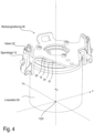
- 3 is one to 2 corresponding side view. 4 is a perspective view of the assembled quick release system in the locked state.
- the quick release system includes according to 2 essentially a chuck 10 ( chuck , clamping chuck ), which can be mechanically coupled to the flange 91 (e.g. by means of screws), an elastic element, which in the present example is designed as a rubber washer 20, and a tool holder 30, which is mechanically rigid with a Machine tool can be coupled.
- an elastic element which in the present example is designed as a rubber washer 20
- a tool holder 30 which is mechanically rigid with a Machine tool can be coupled.
- plastics, in particular elastomers are also suitable materials for the disc 20.
- the flange 91 has a number of threaded bores 210. In the example shown, the flange 91 has six threaded bores 210 , cylindrical pins 11 being screwed into three of the threaded bores 210 .
- the cylinder pins have a cylindrical shape in an upper section and have a thread 110 in a lower section that can be screwed into the threaded bores 210 .
- Cylindrical pins are also often referred to as dowel pins .
- cylindrical pins (without a thread) can also be glued or pressed into the corresponding holes.
- the screwed-in cylindrical pins 11 serve as guides for the tool holder 30, in particular to prevent the tool holder 30 from tilting with respect to the z-axis (axis perpendicular to the plane of the base plate 15, see FIG 2 ) to avoid.
- the pins 11 serve to prevent movement of the mounting plate 31 of the tool holder 30 relative to the base plate 15 of the chuck 10 in a plane (xy plane) parallel to the plane of the plate while allowing some movement normal to that plane.
- the chuck 10 essentially has a base plate 15 and two or more clamps 13 mounted laterally thereon.
- the base plate 15 has a plurality of holes 12 (usually bores).
- the base plate 15 has six holes, whereby the cylinder pins 11 screwed into the flange 91 are inserted through three of the holes 12 and thus determine the position of the chuck.
- the other three holes 12 are for the introduction of screws 14 which can be screwed into corresponding threaded holes 21 in the flange 91 to secure the base plate 15 to the flange 91 to fix.
- the six tapped holes 210 are offset by 60° each, and consequently the three cylindrical pins 11 and the three screws 14 can be arranged offset by 120° each (with respect to the z-axis).
- the base plate 15 has two arms 16 protruding laterally towards the flange 91, which enclose an angle of essentially 90° with the base plate 15 (see FIG 3 ).
- the clamps 13 are mounted on these arms (for example by means of screws).
- the cylinder pins 11 can alternatively also be mounted on the base plate 15 (eg screwed into it) (instead of in the flange 91).
- the in 2 shown variant in which the cylindrical pins 11 are screwed into the flange 91, be better (depending on the specific application).
- the cylindrical pins 11 In order to fulfill their function, the cylindrical pins 11 must protrude from the base plate 15 at right angles to it.
- the tool holder 30 is rigid with a machine tool (in Figures 2-4 not shown) connected.
- the specific construction of the tool holder 30 depends on the machine tool. In particular, those parts of the tool holder 30 that are used to fix the tool holder on the machine tool are variable and adapted to the respective machine tool.
- the tool holder 30 represents an interface, so to speak, which allows the machine tool to be clamped in the chuck 10 .
- the tool holder 30 has a mounting plate 31 with holes 33 and 32 hooks.
- the mounting plate 32 fits the base plate 15 of the chuck 10. In the assembled state, the mounting plate 32 of the tool holder 30 is plugged onto the cylinder pins 11, so that the cylinder pins 11 run through the bores 33.
- the cylindrical pins 11 thus define the position of the tool holder 30 (and thus also the position of the machine tool) in the x and y directions (ie transverse to the z axis in the xy plane).
- the mounting plate 32 of the tool holder 30 rests against the base plate 15 of the chuck 10 and the clamps 13 ( bracket ) are hooked into the associated hook 32 and clamped (the hook is sometimes also referred to as a keeper ).
- Clamp 13 and hook therefore form a draw latch.
- An elastic element in the example shown, a rubber disk 20 arranged between the base plate 15 and the mounting plate 32—allows a small elastic displacement of the tool holder 30 relative to the chuck 10 in the z-direction.
- the elastic element e.g.
- the tension locks draw latches , which each consist of a tension bracket 13 and a hook 31 in combination with the elastic element, are also referred to as dead center locking ( over center latch ), since the tension bracket 13 when locking after hanging in the associated hook 32 is pivoted about the joint 131 to the dead center of the pivoting movement and beyond the dead center.
- the clamping lock/the dead center lock is thus secure against unintentional loosening, since the clamping bracket 13 cannot move back past the dead center without the action of an external force. This external force must be applied manually by a worker when locking and unlocking the toggle latch.
- the rubber sheet 20 is merely an example of an elastic element.
- any elastic element is suitable which is arranged (somewhere in the quick-action clamping system) in such a way that it is elastically deformed when the clamping locks (clamping bracket 13 and hook 32) are locked and, in the locked state, generates a pre-tensioning force between the chuck 10 and the tool holder 30 in the z-direction exerts, which is absorbed by the toggle fasteners.
- the elastic deformation enables a small movement of the tool holder 30 in the z-direction relative to the chuck 10, while a relative movement in the x-direction and y-direction is blocked by the cylindrical pins 11, which serve as linear guides.
- one or more elastic elements can also be integrated into the clamps 13 or the hooks 32.
- the rubber disk 20 can be omitted.
- the hooks 32 and/or part of the tensioning brackets 13 themselves can be formed (at least in part) from an elastic or resilient material. In this case one sometimes also speaks of flexible draw latches or strap closures.
- the clamps 13 can be mounted on the arms 16 of the base plate 15 so that they can be displaced elastically in the z-direction by means of a spring.
- the hooks 32 can be mounted on the mounting plate 31 in an elastically displaceable manner by means of a spring element or another elastic element.
- the bearing bushes of the joints 131 the clamping bracket 13 may be formed from an elastic material and allow the aforementioned elastic deformation when the clamping closures are locked.
- figure 5 illustrates one on a robot (in figure 5 not shown, see 1 ) mounted linear actuator 90 with a locked quick-release system according to the examples Figures 2-4 , wherein a die grinder 50 is attached to the tool holder 30 .
- the tool holder 30 serves as an interface for clamping the machine tool on the chuck 10 of the quick-action clamping system.
- the quick clamping system described here can be used primarily with robots that are able to regulate the contact force between the tool and the workpiece surface.
- this force control can be implemented either with the help of the actuator 90 or - if the robot is suitable for this - by the robot itself.
- the actuator 90 can also be omitted and the chuck 10 can be attached directly to the end effector flange 86 (cf. 1 ) instead of being mounted on the flange 91 of the actuator 90.
- the contact force (process force) is regulated during the surface treatment process, whereby during the treatment process the in Figures 2-4
- the z-direction shown is usually normal to the workpiece surface and the z-direction is also the effective direction of the controlled contact force.
- Any inaccuracies in the positioning of the machine tool in the z-direction are compensated for by the force control, since the machine tool is always pressed against the workpiece with a defined, controlled force. For this reason, inaccuracies in the position of the machine tool, which are a consequence of the deformation of the elastic element (eg rubber disk 20), play no role in practice. These inaccuracies are also compensated almost automatically by the force control.
- any torque acting on the quick-clamping system cannot lead to any appreciable tilting or xy displacement of the tool holder 30 relative to the chuck 10, since these movements are prevented by the cylindrical pins 11 guided in the bores 33. A torque is thus absorbed by the quick-clamping system.
- the only degree of freedom is a (very small) elastic displacement in the z-direction, which, as mentioned, is compensated for by the force control.
- the position of the hook 32 and the clamp 13 can be interchanged, although in practice it probably makes more sense to attach the clamps the base plate of the chuck 10 (and not on the mounting plate 13 of the tool holder 30). Equally, it does not matter whether the dowel pins as in 2 shown are immovable relative to the base plate 15 of the chuck 10 and are passed through holes 33 in the mounting plate 31, or whether the cylinder pins are fixed to the mounting plate 31 (e.g. screwed into it) and passed through corresponding holes in the chuck 10.
- the pins (11) are also not necessarily separate parts and can theoretically also be made in one piece with the base plate 15 or the mounting plate 31 (even if that would be more complicated to manufacture).
- the base plate (or mounting plate) and pins would be an integral part.
- the pins also do not have to be cylindrical. Any shape is possible which can engage a corresponding opening in the opposing part to block movement in a plane parallel to the base and allow small movement perpendicular thereto.
- the linear actuator 90 together with the quick-clamping system and machine tool is not attached to a manipulator (industrial robot), but rather to an immovable (stationary) base.
- the workpiece is held by the robot and positioned in such a way that the machine tool can touch and process the workpiece held by the robot.
- the robot operates under position control and moves the workpiece along a predetermined trajectory during the machining process, while the linear actuator 90 mounted on a fixed base performs the force control and presses the machine tool against the workpiece held by the robot. Examples of such systems - but without a quick release system - are in the publication U.S. 2018/0126512 A1 described.
Description
Die vorliegende Erfindung betrifft ein Schnellspannsystem (quick-clamping system) zur Verbindung von Werkzeugmaschinen mit einem Roboter.The present invention relates to a quick clamping system (quick-clamping system ) for connecting machine tools to a robot.
Bei der robotergestützten Oberflächenbearbeitung wird eine Werkzeugmaschine (z.B. eine Schleifmaschine, eine Bohrmaschine, eine Fräsmaschine, eine Poliermaschine und dgl.) von einem Manipulator, beispielsweise einem Industrieroboter, geführt. Dabei kann die Werkzeugmaschine auf unterschiedliche Weise mit dem sogenannten TCP (Tool Center Point) des Manipulators gekoppelt sein; der Manipulator kann in der Regel Position und Orientierung des TCP praktisch beliebig einstellen, um eine Werkzeugmaschine auf einer Trajektorie z.B. parallel zu einer Oberfläche eines Werkstücks zu bewegen. Industrieroboter sind üblicherweise positionsgeregelt, was eine präzise Bewegung des TCP entlang der gewünschten Trajektorie ermöglicht.In the case of robot-assisted surface processing, a machine tool (for example a grinding machine, a drilling machine, a milling machine, a polishing machine and the like) is guided by a manipulator, for example an industrial robot. The machine tool can be coupled in different ways to the so-called TCP ( Tool Center Point ) of the manipulator; the manipulator can usually adjust the position and orientation of the TCP practically at will in order to move a machine tool on a trajectory, for example parallel to a surface of a workpiece. Industrial robots are usually position-controlled, which allows precise movement of the TCP along the desired trajectory.
Um beim robotergestützten Schleifen oder bei anderen Oberflächenbearbeitungsprozessen ein gutes Ergebnis zu erzielen, ist in vielen Anwendungen eine Regelung der Prozesskraft (Schleifkraft) nötig, was mit herkömmlichen Industrierobotern oft nur schwer mit hinreichender Genauigkeit zu realisieren ist. Die großen und schweren Armsegmente eines Industrieroboters besitzen eine zu große Massenträgheit, als dass ein Regler (closedloop controller) rasch genug auf Schwankungen der Prozesskraft reagieren könnte. Um dieses Problem zu lösen, kann zwischen dem TCP des Manipulators und der Werkzeugmaschine ein im Vergleich zum Industrieroboter kleiner (und leichter) Linearaktor angeordnet sein, der den TCP des Manipulators mit der Werkzeugmaschine koppelt. Der Linearaktor regelt während der Oberflächenbearbeitung lediglich die Prozesskraft (also die Anpresskraft zwischen Werkzeug und Werkstück), während der Manipulator die Werkzeugmaschine samt Linearaktor positionsgeregelt entlang der gewünschten Trajektorie bewegt. Durch die Kraftregelung kann der Linearaktor Ungenauigkeiten in der Lage und der Form des zu bearbeitenden Werkstücks sowie auch Ungenauigkeiten der Trajektorie des Manipulators (innerhalb gewisser Grenzen) ausgleichen. Nichtsdestotrotz gibt es Roboter, die in der Lage sind, auch ohne den erwähnten Linearaktor mittels Kraft-/Momenten-Regelung die Prozesskraft einzustellen.In order to achieve a good result with robot-assisted grinding or other surface treatment processes, the process force (grinding force) must be controlled in many applications, which is often difficult to achieve with sufficient accuracy using conventional industrial robots. The large and heavy arm segments of an industrial robot have too much inertia for a closed loop controller to react quickly enough to fluctuations in the process force. In order to solve this problem, a linear actuator which is smaller (and lighter) than the industrial robot and which couples the TCP of the manipulator to the machine tool can be arranged between the TCP of the manipulator and the machine tool. The linear actuator only regulates the process force (i.e. the contact pressure) during surface processing between tool and workpiece), while the manipulator moves the machine tool together with the linear actuator under position control along the desired trajectory. By controlling the force, the linear actuator can compensate for inaccuracies in the position and shape of the workpiece to be machined as well as inaccuracies in the trajectory of the manipulator (within certain limits). Nevertheless, there are robots that are able to adjust the process force by means of force/torque control even without the linear actuator mentioned.
Es sind verschiedene Spannsysteme bekannt, die dafür geeignet sind, verschiedene Werkzeugmaschinen mit dem Roboter zu verbinden und wieder zu lösen. In diesem Zusammenhang sei z.B. auf die Publikationen
Der Erfinder hat sich die Aufgabe gestellt, ein vergleichsweise einfaches und für viele Anwendung ausreichend präzises Schnellspannsystem für die Verbindung von Werkzeugmaschinen zu schaffen,The inventor has set himself the task of creating a comparatively simple quick-clamping system that is sufficiently precise for many applications for connecting machine tools.
Die oben genannte Aufgabe wird durch die Vorrichtung gemäß Patentanspruch 1 gelöst. Verschiedene Ausführungsformen und Weiterentwicklungen sind Gegenstand der abhängigen Patentansprüche.The above object is achieved by the device according to patent claim 1. Various embodiments and further developments are the subject matter of the dependent patent claims.
Es wird ein Schnellspannsystem zur Montage eines Werkzeugs oder einer Werkzeugmaschine an einem Manipulator beschrieben. Gemäß einem Ausführungsbeispiel umfasst das Schnellspannsystem folgendes: ein Spannfutter mit einer Grundplatte, welche dazu ausgebildet ist, an einem von einem Manipulator positionierbaren Flansch montiert zu werden; eine Werkzeughalterung, die zur Montage an einer Werkzeugmaschine ausgebildet ist, wobei die Werkzeughalterung eine Montageplatte aufweist, die in verriegeltem Zustand an der Grundplatte des Spannfutters anliegt; zwei oder mehr Stifte, die dazu ausgebildet sind, in montiertem Zustand die Montageplatte an der Grundplatte auszurichten und eine Bewegung der Montageplatte relativ zu der Grundplatte in einer Ebene parallel zur Grundplatte zu verhindern; mindestens ein elastisches Element; und einen Spannverschluss, der dazu ausgebildet ist, die Werkzeughalterung an der Grundplatte des Spannfutters zu verriegeln, wobei im verriegelten Zustand das elastische Element deformiert ist und eine Vorspannkraft zwischen der Grundplatte und der Montageplatte bewirkt und wobei das mindestens eine elastische Element eine Scheibe aus elastischem Material umfasst, die zwischen der Grundplatte und Montageplatte angeordnet ist.A quick-clamping system for mounting a tool or a machine tool on a manipulator is described. According to an exemplary embodiment, the quick-clamping system comprises the following: a chuck with a base plate which is designed to be mounted on a flange which can be positioned by a manipulator; a tool holder which is designed for mounting on a machine tool, the tool holder having a mounting plate which, in the locked state, bears against the base plate of the chuck; two or more pins which are designed to align the mounting plate to the base plate in the assembled state and a movement of the mounting plate relative to the base plate in a plane parallel to the to prevent base plate; at least one elastic element; and a clamping lock which is designed to lock the tool holder on the base plate of the chuck, the elastic element being deformed in the locked state and causing a prestressing force between the base plate and the mounting plate, and the at least one elastic element being a disc made of elastic material includes, which is arranged between the base plate and mounting plate.
Verschiedene Implementierungen werden nachfolgend anhand von den in den Abbildungen dargestellten Beispielen näher erläutert. Die Darstellungen sind nicht zwangsläufig maßstabsgetreu und die Erfindung beschränkt sich nicht nur auf die dargestellten Aspekte. Vielmehr wird Wert darauf gelegt, die den dargestellten Ausführungsbeispielen zugrunde liegenden Prinzipien darzustellen.
-
Figur 1 ist eine exemplarische schematische Darstellung einer robotergestützten Schleifvorrichtung mit einer Schleifmaschine, die mit einem Industrieroboter mittels eines kraftgeregelten Linearaktors gekoppelt ist; der Linearaktor bewirkt eine teilweise mechanische Entkopplung von Industrieroboter und Schleifmaschine. -
Figur 2 ist eine perspektivische Explosionsdarstellung eines Beispiels eines Schnellspannsystems zur Verbindung einer Werkzeugmaschine mit einem Roboter. -
Figur 3 ist eine Seitenansicht des Beispiels ausFig. 2 . -
Figur 4 ist eine perspektivische Darstellung des Schnellspannsystems in geklemmten Zustand. -
Figur 5 illustriert das System ausFig. 4 inklusive Werkzeugmaschine.
-
figure 1 Fig. 12 is an exemplary schematic representation of a robotic grinding apparatus with a grinding machine coupled to an industrial robot by means of a force-controlled linear actuator; the linear actuator causes a partial mechanical decoupling of the industrial robot and grinding machine. -
figure 2 12 is an exploded perspective view of an example of a quick release system for connecting a machine tool to a robot. -
figure 3 Fig. 12 is a side view of the example2 . -
figure 4 is a perspective view of the quick release system in the clamped state. -
figure 5 illustrates the system4 including machine tool.
Bevor verschiedene Ausführungsbeispiele im Detail erläutert werden, wird zunächst ein allgemeines Beispiel einer robotergestützten Schleifvorrichtung beschrieben. Es versteht sich, dass die hier beschriebenen Konzepte auch auf andere Arten von Oberflächenbearbeitung (z.B. Polieren, Fräsen, Bohren, etc.) übertragbar und nicht auf Schleifen beschränkt sind. Mit dem hier beschriebenen Schnellspannsystem können praktisch beliebige Komponenten schnell mit einem Roboter verbunden werden.Before various exemplary embodiments are explained in detail, a general example of a robot-assisted grinding device will first be described. It goes without saying that the concepts described here can also be transferred to other types of surface treatment (e.g. polishing, milling, drilling, etc.) and not to grinding are limited. With the quick clamping system described here, practically any component can be quickly connected to a robot.
Gemäß
Im Falle eines Industrieroboters mit sechs Freiheitsgraden kann der Manipulator 80 aus vier Segmenten 82, 83, 84 und 85 aufgebaut sein, die jeweils über Gelenke G11, G12 und G13 verbunden sind. Das erste Segment 82 ist dabei meist starr mit einem Fundament 81 verbunden (was jedoch nicht zwangsläufig der Fall sein muss). Das Gelenk G11 verbindet die Segmente 82 und 83. Das Gelenk G11 kann 2-achsig sein und eine Drehung des Segments 83 um eine horizontale Drehachse (Elevationswinkel) und eine vertikale Drehachse (Azimutwinkel) ermöglichen. Das Gelenk G12 verbindet die Segmente 83 und 84 und ermöglicht eine Schwenkbewegung des Segments 84 relativ zur Lage des Segments 83. Das Gelenk G13 verbindet die Segmente 84 und 85. Das Gelenk G13 kann 2-achsig sein und daher (ähnlich wie das Gelenk G11) eine Schwenkbewegung in zwei Richtungen ermöglichen. Der TCP hat eine feste Relativposition zum Segment 85, wobei dieses üblicherweise noch ein Drehgelenk (nicht dargestellt) umfasst, welches eine Drehbewegung des am Segment 85 angeordneten Endeffektorflansches 86 um eine Längsachse A des Segments 85 ermöglicht (in
Der Manipulator 80 ist üblicherweise positionsgeregelt, d.h. die Robotersteuerung kann die Pose (Ort und Orientierung) des TCP festlegen und diesen entlang einer vordefinierten Trajektorie bewegen. In
Wie bereits erwähnt, kann während des Schleifprozesses die Kontaktkraft FK zwischen Schleifwerkzeug (Schleifmaschine 50 mit Schleifscheibe 51) und Werkstück 60 mit Hilfe des Linear-Aktors 90 und einer Kraftregelung (die beispielsweise in der Steuerung 70 implementiert sein kann) so eingestellt werden, dass die Kontaktkraft FK (in Richtung der Längsachse A) zwischen Schleifscheibe 51 und Werkstück 60 einem vorgebbaren Sollwert entspricht. Die Kontaktkraft FK ist dabei eine Reaktion auf die Aktorkraft FA, mit der der Linearaktor 90 auf die Werkstückoberfläche drückt. Bei fehlendem Kontakt zwischen Werkstück 60 und Werkzeug 51 fährt der Aktor 90 aufgrund der fehlenden Kontaktkraft am Werkstück 60 gegen einen Endanschlag (nicht dargestellt da im Aktor 2 integriert) und drückt mit einer definierten Kraft gegen diesen. Die Kraftregelung ist dabei durchgehend aktiv. In dieser Situation (kein Kontakt) ist die Aktorauslenkung daher maximal und der Aktor 90 befindet sich in einer Endposition. Die definierte Kraft, mit der der Aktor 90 gegen den Endanschlag drückt kann sehr klein sein oder (theoretisch) sogar auf null geregelt werden, um ein möglichst sanftes Kontaktieren der Werkstückoberfläche zu ermöglichen.As already mentioned, during the grinding process, the contact force F K between the grinding tool (grinding
Die Positionsregelung des Manipulators 80 (die ebenfalls in der Steuerung 70 implementiert sein kann) kann vollkommen unabhängig von der Kraftregelung des Aktors 90 arbeiten. Der Aktor 90 ist nicht verantwortlich für die Positionierung der Schleifmaschine 50, sondern lediglich für das Einstellen und Aufrechterhalten der erwünschten Kontaktkraft FK während des Schleifprozesses und zur Erkennung von Kontakt zwischen Werkzeug 51 und Werkstück 60. Ein Kontakt kann z.B. in einfacher Weise dadurch erkannt werden, dass der Aktor sich aus der Endposition herausbewegt hat (Aktorauslenkung a ist kleiner als die maximale Auslenkung aMAX am Endanschlag).The position control of the manipulator 80 (which can also be implemented in the controller 70) can work completely independently of the force control of the
Der Aktor 90 kann ein pneumatischer Aktor sein, z.B. ein doppeltwirkender Pneumatikzylinder. Jedoch sind auch andere pneumatische Aktoren anwendbar wie z.B. Balgzylinder und Luftmuskel. Als Alternative kommen auch elektrische Direktantriebe (getriebelos) in Betracht. Es versteht sich, dass die Wirkrichtung des Aktors 90 und die Drehachse der Schleifmaschine 50 nicht notwendigerweise mit der Längsachse A des Segments 85 des Manipulators 80 zusammenfallen müssen. Im Falle eines pneumatischen Aktors kann die Kraftregelung in an sich bekannter Weise mit Hilfe eines Regelventils, eines Reglers (z.B. implementiert in der Steuerung 70) und eines Druckluftspeichers oder Kompressors realisiert werden. Da für die Berücksichtigung der Schwerkraft (d.h. der Gewichtskraft der Schleifmaschine 50) die Neigung zur Lotrechten relevant ist, kann der Aktor 2 einen Neigungssensor enthalten oder diese Information kann basierend auf den Gelenkwinkeln des Manipulators 80 ermittelt werden. Die ermittelte Neigung wird von dem Kraftregler berücksichtigt. Die konkrete Implementierung der Kraftregelung ist an sich bekannt und für die weitere Erläuterung nicht wichtig und wird daher auch nicht detaillierter beschrieben. Der Aktor 90 ermöglicht nicht nur eine gewisse mechanische Entkopplung zwischen Manipulator 80 und Werkstück 60, sondern ist auch in der Lage, Ungenauigkeiten in der Positionierung des TCP auszugleichen.
Das Schnellspannsystem umfasst gemäß
Das Spannfutter 10 weist im Wesentlichen ein Grundplatte 15 und zwei oder mehr seitlich daran montierte Spannbügel 13 auf. Die Grundplatte 15 weist mehrere Löcher 12 (in der Regel Bohrungen) auf. In dem Beispiel aus
Die Grundplatte 15 weist seitlich zwei zum Flansch 91 hin abstehende Ausleger 16 auf, die mit der Grundplatte 15 einen Winkel von im Wesentlichen 90° einschließen (siehe
Die Werkzeughalterung 30 ist starr mit einer Werkzeugmaschine (in
Die Spannverschlüsse (draw latches), die jeweils aus einem Spannbügel 13 und einem Haken 31 in Kombination mit dem elastischen Element benötigt werden, werden auch als Totpunktverriegelung (over center latch) bezeichnet, da der Spannbügel 13 beim Verriegeln nach dem Einhängen in den zugehörigen Haken 32 um das Gelenk 131 bis zum Totpunkt der Schwenkbewegung und über den Totpunkt hinaus geschwenkt wird. Der Spannverschluss / die Totpunktverriegelung ist damit sicher gegen ein unbeabsichtigtes Lösen, da der Spannbügel 13 nicht ohne externe Krafteinwirkung sich über den Totpunkt zurück bewegen kann. Diese externe Kraft muss beim Verriegeln und beim Entriegeln des Spannverschlusses von einem Arbeiter manuell aufgewendet werden.The tension locks ( draw latches ), which each consist of a tension bracket 13 and a
An dieser Stelle sei angemerkt, dass die Gummiplatte 20 lediglich ein Beispiel für ein elastisches Element. Im Allgemeinen ist jedes elastische Element geeignet, welches (irgendwo im Schnellspannsystem) so angeordnet ist, dass es beim Verriegeln der Spannverschlüsse (Spannbügel 13 und Haken 32) elastisch deformiert wird und im verriegelten Zustand eine Vorspannkraft zwischen Spannfutter 10 und Werkzeughalterung 30 in z-Richtung ausübt, die von den Spannverschlüssen aufgenommen wird. Durch die elastische Deformation wird eine kleine Bewegung der Werkzeughalterung 30 in z-Richtung relativ zum Spannfutter 10 ermöglicht, während eine Relativbewegung in x-Richtung und y-Richtung durch die Zylinderstifte 11, die als Linearführung dienen, blockiert wird. Alternativ zu der Gummischeibe 20 können ein oder mehrere elastische Elemente auch in die Spannbügel 13 oder die Haken 32 integriert sein. In diesem Fall kann die Gummischeibe 20 weggelassen werden. Beispielsweise können die Haken 32 und/oder ein Teil der Spannbügel 13 selbst aus einem elastischen oder nachgiebigen Material gebildet sein (zumindest teilweise). In diesem Fall spricht man manchmal auch von flexiblen Spannverschlüssen (flexible draw latches) oder Spannbandverschlüssen. Alternativ können die Spannbügel 13 mittels einer Feder in z-Richtung an den Auslegern 16 der Grundplatte 15 elastisch verschiebbar gelagert sein. Zusätzlich oder alternativ können die Haken 32 mittels eines Federelementes oder eines anderen elastischen Elementes elastisch verschiebbar an der Montageplatte 31 gelagert sein. Zusätzlich oder alternativ können auch die Lagerbuchsen der Gelenke 131 der Spannbügel 13 aus einem elastischen Material geformt sein und die erwähnte elastische Deformation bei der Verriegelung der Spannverschlüsse zulassen.At this point it should be noted that the
Das hier beschriebene Schnellspannsystem kann vor allem bei Robotern eingesetzt werden, die in der Lage sind die Kontaktkraft zwischen Werkzeug und Werkstückoberfläche zu regeln. Wie erwähnt kann diese Kraftregelung entweder mit Hilfe des Aktors 90 umgesetzt werden oder - sofern der Roboter dafür geeignet ist - durch den Roboter selbst. In diesem Fall kann der Aktor 90 auch weggelassen werden und das Spannfutter 10 kann direkt am Endeffektorflansch 86 (vgl.
Schließlich sei noch angemerkt, dass die Position von Haken 32 und Spannbügel 13 vertauschbar sind, obwohl es in der Praxis vermutlich sinnvoller ist, die Spannbügel an der Grundplatte des Spannfutters 10 zu lagern (und nicht an der Montageplatte 13 der Werkzeughalterung 30). Gleichermaßen spielt es keine Rolle, ob die Zylinderstifte wie in
In einem weiteren Beispiel ist der Linearaktor 90 samt Schnellspannsystem und Werkzeugmaschine nicht an einem Manipulator (Industrieroboter) befestigt, sondern an einer unbeweglichen (ortsfeste) Basis. In diesem Fall wird von dem Roboter das Werkstück gehalten und so positioniert, dass die Werkzeugmaschine das vom Roboter gehaltene Werkstück berührt und bearbeiten kann. Der Roboter arbeitet positionsgeregelt und bewegt das Werkstück während des Bearbeitungsprozesses entlang einer vorgegebenen Trajektorie, während der an einer festen Basis montierte Linearaktor 90 die Kraftregelung durchführt und die Werkzeugmaschine gegen das vom Roboter gehaltene Werkstück drückt. Beispiele derartige Systeme - jedoch ohne Schnellspannsystem - sind in der Publikation
Claims (8)
- A rapid clamping system, comprising:a chuck (10) with a base plate (15) configured to be assembled with a flange (86, 91) which is positionable in a force-controlled manner by means of a manipulator (80, 90) or a linear actuator (90),a tool holder (30) configured to be assembled with a machine tool, wherein the tool holder has an assembly plate (31) which rests against the base plate (15) in a locked state;two or more pins (11) configured to align the assembly plate (31) with the base plate (15) in an assembled state and to prevent a movement of the assembly plate (31) relative to the base plate (15) in a plane parallel to the base plate (15);at least one elastic member (20), comprising a disc made of elastic material interposed between the base plate (15) and the assembly plate (31); anda clamping lock (13, 32) configured to lock the tool holder (30) to the base plate (15) of the chuck (10), wherein the elastic member (20) is deformed in the locked state and causes a biasing force between the base plate (15) and the assembly plate (31).
- The rapid clamping system according to claim 1,
wherein the clamping lock comprises a plurality of clamps (13) and hooks (32) associated with the clamps (13). - The rapid clamping system according to claim 2,wherein the hooks (32) are assembled with the tool holder (30) and the clamps are mounted pivotably with the base plate (15), orwherein the hooks (32) are assembled with the base plate (15) and the clamps are pivotably mounted on the tool holder (30).
- The rapid clamping system according to any one of claims 1 to 3,wherein the pins (11) extend to corresponding holes in the assembly plate (31) in the assembled state, and/orwherein the pins (11) extend to corresponding holes in the base plate (32) in the assembled state.
- The rapid clamping system according to any one of claims 1 to 4,
wherein the pins (11) are assembled with the flange (86, 91) and extend through corresponding holes (12, 33) of the base plate (15) and the assembly plate (31). - The rapid clamping system according to any one of claims 1 to 5,
wherein the clamping lock (13, 32) comprises a dead center lock. - A device for robotic machining of a surface of a workpiece, having:a rapid clamping system according to any one of claims 1 to 6, wherein the flange positionable in a force-controlled manner is a first flange of the linear actuator (90),a manipulator (80), wherein a second flange of the linear actuator (90) is coupled to an end effector flange (86) of the manipulator (80),wherein the manipulator (80) is configured to position the linear actuator (90) together with the machine tool (50) coupled to the linear actuator (90) via the rapid clamping system in a position-controlled manner relative to the workpiece (60), and the linear actuator (90) is configured to adjust a force between the machine tool (50) and the workpiece (60).
- A device for robotic machining of a surface of a workpiece, having:a rapid clamping system according to any one of claims 1 to 6,wherein the flange positionable in a force-controlled manner is a first flange of the linear actuator (90),a stationary base which a second flange of the linear actuator is assembled with;a manipulator (80) configured to hold the workpiece and to position it in a position-controlled manner relative to a machine tool (50) coupled to the linear actuator via the rapid clamping system,wherein the linear actuator (90) is configured to adjust a force between the machine tool and the workpiece.
Applications Claiming Priority (2)
| Application Number | Priority Date | Filing Date | Title |
|---|---|---|---|
| DE102020111292.0A DE102020111292A1 (en) | 2020-04-24 | 2020-04-24 | QUICK CLAMPING SYSTEM FOR CONNECTING MACHINE TOOLS WITH A ROBOT |
| PCT/EP2021/060529 WO2021214217A1 (en) | 2020-04-24 | 2021-04-22 | Rapid clamping system for connecting machine tools to a robot |
Publications (2)
| Publication Number | Publication Date |
|---|---|
| EP3934862A1 EP3934862A1 (en) | 2022-01-12 |
| EP3934862B1 true EP3934862B1 (en) | 2023-06-21 |
Family
ID=75690278
Family Applications (1)
| Application Number | Title | Priority Date | Filing Date |
|---|---|---|---|
| EP21721895.7A Active EP3934862B1 (en) | 2020-04-24 | 2021-04-22 | Rapid clamping system for connecting machine tools to a robot |
Country Status (7)
| Country | Link |
|---|---|
| US (1) | US20230182320A1 (en) |
| EP (1) | EP3934862B1 (en) |
| JP (1) | JP2023523046A (en) |
| KR (1) | KR20230006512A (en) |
| CN (1) | CN115666875A (en) |
| DE (1) | DE102020111292A1 (en) |
| WO (1) | WO2021214217A1 (en) |
Citations (2)
| Publication number | Priority date | Publication date | Assignee | Title |
|---|---|---|---|---|
| DE29922796U1 (en) * | 1999-12-24 | 2000-08-17 | Staeubli Vertriebs Gmbh | Automatic robot change system for changing grippers on the robot |
| US8857821B2 (en) * | 2008-09-05 | 2014-10-14 | Ati Industrial Automation, Inc. | Manual robotic tool changer with rotating piston |
Family Cites Families (4)
| Publication number | Priority date | Publication date | Assignee | Title |
|---|---|---|---|---|
| DE10326239B4 (en) * | 2003-06-11 | 2007-05-16 | Ass Maschb Gmbh | Quick-change system |
| DE102015106480A1 (en) | 2015-04-27 | 2016-10-27 | Ferrobotics Compliant Robot Technology Gmbh | Device for surface treatment |
| CN110576346A (en) * | 2019-09-03 | 2019-12-17 | 中科君胜(深圳)智能数据科技发展有限公司 | Flexible actuator capable of automatically polishing by robot and polishing method thereof |
| CN111002155A (en) * | 2019-11-27 | 2020-04-14 | 中国科学院上海光学精密机械研究所 | Polishing force control flexible polishing tool |
-
2020
- 2020-04-24 DE DE102020111292.0A patent/DE102020111292A1/en active Pending
-
2021
- 2021-04-22 KR KR1020227040392A patent/KR20230006512A/en unknown
- 2021-04-22 WO PCT/EP2021/060529 patent/WO2021214217A1/en unknown
- 2021-04-22 US US17/920,964 patent/US20230182320A1/en active Pending
- 2021-04-22 JP JP2022564631A patent/JP2023523046A/en active Pending
- 2021-04-22 CN CN202180037744.9A patent/CN115666875A/en active Pending
- 2021-04-22 EP EP21721895.7A patent/EP3934862B1/en active Active
Patent Citations (2)
| Publication number | Priority date | Publication date | Assignee | Title |
|---|---|---|---|---|
| DE29922796U1 (en) * | 1999-12-24 | 2000-08-17 | Staeubli Vertriebs Gmbh | Automatic robot change system for changing grippers on the robot |
| US8857821B2 (en) * | 2008-09-05 | 2014-10-14 | Ati Industrial Automation, Inc. | Manual robotic tool changer with rotating piston |
Also Published As
| Publication number | Publication date |
|---|---|
| KR20230006512A (en) | 2023-01-10 |
| DE102020111292A1 (en) | 2021-10-28 |
| CN115666875A (en) | 2023-01-31 |
| JP2023523046A (en) | 2023-06-01 |
| WO2021214217A1 (en) | 2021-10-28 |
| US20230182320A1 (en) | 2023-06-15 |
| EP3934862A1 (en) | 2022-01-12 |
Similar Documents
| Publication | Publication Date | Title |
|---|---|---|
| EP3439836B1 (en) | Robot-aided grinding apparatus | |
| EP3325214B1 (en) | Machine tool for robot-assisted surface finishing | |
| EP3325232B1 (en) | Compensating device for a handling unit and handling unit comprising the compensating device | |
| EP3481605B1 (en) | Method and system for automatically changing shafts | |
| DE102018203626B3 (en) | Multiple gripper device for a robot | |
| WO2012123552A1 (en) | Active handling apparatus and method for contact tasks | |
| DE102018106086A1 (en) | SPEED CONTROL IN ROBOT-BASED GRINDING | |
| DE102015119589B4 (en) | Device and method for robotic roller hemming | |
| DE102013227147A1 (en) | Method for the automated rotary joining and / or rotary lifting of components, as well as associated industrial robots and automated assembly workstation | |
| EP3980227A2 (en) | Compensation of positional tolerances in the robot-assisted surface machining | |
| EP3288712B1 (en) | Device for machining surfaces | |
| DE102020101384A1 (en) | ROBOT-BASED GRINDING DEVICE WITH INTEGRATED MAINTENANCE UNIT | |
| EP3934862B1 (en) | Rapid clamping system for connecting machine tools to a robot | |
| DE102020110492A1 (en) | DEVICE FOR ROBOTIC PROCESSING OF SURFACES | |
| DE102022110487A1 (en) | PNEUMATIC LINEAR ACTUATOR | |
| WO2019077007A1 (en) | Extraction system for grinding tool with radial disc brush | |
| EP3999277B1 (en) | Device and method for automatically removing grinding wheels | |
| DE3708363A1 (en) | CHUCK FOR MACHINE TOOLS | |
| DE102018001131A1 (en) | Device for supporting a workpiece to be machined | |
| AT524630B1 (en) | Bending system and manipulator with rotatable gripper arrangement | |
| DE102021106990A1 (en) | Force-controlled handling device for robot-assisted surface treatment | |
| WO2022207409A1 (en) | System and method for executing an assembly task by means of a robot |
Legal Events
| Date | Code | Title | Description |
|---|---|---|---|
| STAA | Information on the status of an ep patent application or granted ep patent |
Free format text: STATUS: UNKNOWN |
|
| STAA | Information on the status of an ep patent application or granted ep patent |
Free format text: STATUS: THE INTERNATIONAL PUBLICATION HAS BEEN MADE |
|
| PUAI | Public reference made under article 153(3) epc to a published international application that has entered the european phase |
Free format text: ORIGINAL CODE: 0009012 |
|
| STAA | Information on the status of an ep patent application or granted ep patent |
Free format text: STATUS: REQUEST FOR EXAMINATION WAS MADE |
|
| 17P | Request for examination filed |
Effective date: 20211005 |
|
| AK | Designated contracting states |
Kind code of ref document: A1 Designated state(s): AL AT BE BG CH CY CZ DE DK EE ES FI FR GB GR HR HU IE IS IT LI LT LU LV MC MK MT NL NO PL PT RO RS SE SI SK SM TR |
|
| GRAP | Despatch of communication of intention to grant a patent |
Free format text: ORIGINAL CODE: EPIDOSNIGR1 |
|
| STAA | Information on the status of an ep patent application or granted ep patent |
Free format text: STATUS: GRANT OF PATENT IS INTENDED |
|
| INTG | Intention to grant announced |
Effective date: 20230131 |
|
| GRAS | Grant fee paid |
Free format text: ORIGINAL CODE: EPIDOSNIGR3 |
|
| GRAA | (expected) grant |
Free format text: ORIGINAL CODE: 0009210 |
|
| STAA | Information on the status of an ep patent application or granted ep patent |
Free format text: STATUS: THE PATENT HAS BEEN GRANTED |
|
| AK | Designated contracting states |
Kind code of ref document: B1 Designated state(s): AL AT BE BG CH CY CZ DE DK EE ES FI FR GB GR HR HU IE IS IT LI LT LU LV MC MK MT NL NO PL PT RO RS SE SI SK SM TR |
|
| DAV | Request for validation of the european patent (deleted) | ||
| DAX | Request for extension of the european patent (deleted) | ||
| REG | Reference to a national code |
Ref country code: CH Ref legal event code: EP |
|
| REG | Reference to a national code |
Ref country code: DE Ref legal event code: R096 Ref document number: 502021000906 Country of ref document: DE |
|
| REG | Reference to a national code |
Ref country code: AT Ref legal event code: REF Ref document number: 1580584 Country of ref document: AT Kind code of ref document: T Effective date: 20230715 |
|
| REG | Reference to a national code |
Ref country code: IE Ref legal event code: FG4D Free format text: LANGUAGE OF EP DOCUMENT: GERMAN |
|
| REG | Reference to a national code |
Ref country code: LT Ref legal event code: MG9D |
|
| REG | Reference to a national code |
Ref country code: NL Ref legal event code: MP Effective date: 20230621 |
|
| PG25 | Lapsed in a contracting state [announced via postgrant information from national office to epo] |
Ref country code: SE Free format text: LAPSE BECAUSE OF FAILURE TO SUBMIT A TRANSLATION OF THE DESCRIPTION OR TO PAY THE FEE WITHIN THE PRESCRIBED TIME-LIMIT Effective date: 20230621 Ref country code: NO Free format text: LAPSE BECAUSE OF FAILURE TO SUBMIT A TRANSLATION OF THE DESCRIPTION OR TO PAY THE FEE WITHIN THE PRESCRIBED TIME-LIMIT Effective date: 20230921 |
|
| PG25 | Lapsed in a contracting state [announced via postgrant information from national office to epo] |
Ref country code: RS Free format text: LAPSE BECAUSE OF FAILURE TO SUBMIT A TRANSLATION OF THE DESCRIPTION OR TO PAY THE FEE WITHIN THE PRESCRIBED TIME-LIMIT Effective date: 20230621 Ref country code: NL Free format text: LAPSE BECAUSE OF FAILURE TO SUBMIT A TRANSLATION OF THE DESCRIPTION OR TO PAY THE FEE WITHIN THE PRESCRIBED TIME-LIMIT Effective date: 20230621 Ref country code: LV Free format text: LAPSE BECAUSE OF FAILURE TO SUBMIT A TRANSLATION OF THE DESCRIPTION OR TO PAY THE FEE WITHIN THE PRESCRIBED TIME-LIMIT Effective date: 20230621 Ref country code: LT Free format text: LAPSE BECAUSE OF FAILURE TO SUBMIT A TRANSLATION OF THE DESCRIPTION OR TO PAY THE FEE WITHIN THE PRESCRIBED TIME-LIMIT Effective date: 20230621 Ref country code: HR Free format text: LAPSE BECAUSE OF FAILURE TO SUBMIT A TRANSLATION OF THE DESCRIPTION OR TO PAY THE FEE WITHIN THE PRESCRIBED TIME-LIMIT Effective date: 20230621 Ref country code: GR Free format text: LAPSE BECAUSE OF FAILURE TO SUBMIT A TRANSLATION OF THE DESCRIPTION OR TO PAY THE FEE WITHIN THE PRESCRIBED TIME-LIMIT Effective date: 20230922 |
|
| PG25 | Lapsed in a contracting state [announced via postgrant information from national office to epo] |
Ref country code: FI Free format text: LAPSE BECAUSE OF FAILURE TO SUBMIT A TRANSLATION OF THE DESCRIPTION OR TO PAY THE FEE WITHIN THE PRESCRIBED TIME-LIMIT Effective date: 20230621 |
|
| PG25 | Lapsed in a contracting state [announced via postgrant information from national office to epo] |
Ref country code: SK Free format text: LAPSE BECAUSE OF FAILURE TO SUBMIT A TRANSLATION OF THE DESCRIPTION OR TO PAY THE FEE WITHIN THE PRESCRIBED TIME-LIMIT Effective date: 20230621 |
|
| PG25 | Lapsed in a contracting state [announced via postgrant information from national office to epo] |
Ref country code: ES Free format text: LAPSE BECAUSE OF FAILURE TO SUBMIT A TRANSLATION OF THE DESCRIPTION OR TO PAY THE FEE WITHIN THE PRESCRIBED TIME-LIMIT Effective date: 20230621 |
|
| PG25 | Lapsed in a contracting state [announced via postgrant information from national office to epo] |
Ref country code: IS Free format text: LAPSE BECAUSE OF FAILURE TO SUBMIT A TRANSLATION OF THE DESCRIPTION OR TO PAY THE FEE WITHIN THE PRESCRIBED TIME-LIMIT Effective date: 20231021 |
|
| PG25 | Lapsed in a contracting state [announced via postgrant information from national office to epo] |
Ref country code: SM Free format text: LAPSE BECAUSE OF FAILURE TO SUBMIT A TRANSLATION OF THE DESCRIPTION OR TO PAY THE FEE WITHIN THE PRESCRIBED TIME-LIMIT Effective date: 20230621 Ref country code: SK Free format text: LAPSE BECAUSE OF FAILURE TO SUBMIT A TRANSLATION OF THE DESCRIPTION OR TO PAY THE FEE WITHIN THE PRESCRIBED TIME-LIMIT Effective date: 20230621 Ref country code: RO Free format text: LAPSE BECAUSE OF FAILURE TO SUBMIT A TRANSLATION OF THE DESCRIPTION OR TO PAY THE FEE WITHIN THE PRESCRIBED TIME-LIMIT Effective date: 20230621 Ref country code: PT Free format text: LAPSE BECAUSE OF FAILURE TO SUBMIT A TRANSLATION OF THE DESCRIPTION OR TO PAY THE FEE WITHIN THE PRESCRIBED TIME-LIMIT Effective date: 20231023 Ref country code: IS Free format text: LAPSE BECAUSE OF FAILURE TO SUBMIT A TRANSLATION OF THE DESCRIPTION OR TO PAY THE FEE WITHIN THE PRESCRIBED TIME-LIMIT Effective date: 20231021 Ref country code: ES Free format text: LAPSE BECAUSE OF FAILURE TO SUBMIT A TRANSLATION OF THE DESCRIPTION OR TO PAY THE FEE WITHIN THE PRESCRIBED TIME-LIMIT Effective date: 20230621 Ref country code: EE Free format text: LAPSE BECAUSE OF FAILURE TO SUBMIT A TRANSLATION OF THE DESCRIPTION OR TO PAY THE FEE WITHIN THE PRESCRIBED TIME-LIMIT Effective date: 20230621 Ref country code: CZ Free format text: LAPSE BECAUSE OF FAILURE TO SUBMIT A TRANSLATION OF THE DESCRIPTION OR TO PAY THE FEE WITHIN THE PRESCRIBED TIME-LIMIT Effective date: 20230621 |
|
| PG25 | Lapsed in a contracting state [announced via postgrant information from national office to epo] |
Ref country code: PL Free format text: LAPSE BECAUSE OF FAILURE TO SUBMIT A TRANSLATION OF THE DESCRIPTION OR TO PAY THE FEE WITHIN THE PRESCRIBED TIME-LIMIT Effective date: 20230621 |