EP3288712B1 - Device for machining surfaces - Google Patents
Device for machining surfaces Download PDFInfo
- Publication number
- EP3288712B1 EP3288712B1 EP16724583.6A EP16724583A EP3288712B1 EP 3288712 B1 EP3288712 B1 EP 3288712B1 EP 16724583 A EP16724583 A EP 16724583A EP 3288712 B1 EP3288712 B1 EP 3288712B1
- Authority
- EP
- European Patent Office
- Prior art keywords
- roller
- force
- actuator
- belt
- frame
- Prior art date
- Legal status (The legal status is an assumption and is not a legal conclusion. Google has not performed a legal analysis and makes no representation as to the accuracy of the status listed.)
- Active
Links
- 238000003754 machining Methods 0.000 title claims description 12
- 238000000034 method Methods 0.000 claims description 10
- 238000005259 measurement Methods 0.000 claims description 4
- 230000000694 effects Effects 0.000 claims 1
- 238000000227 grinding Methods 0.000 description 57
- 238000012545 processing Methods 0.000 description 12
- 239000000463 material Substances 0.000 description 3
- 230000000903 blocking effect Effects 0.000 description 2
- 239000000969 carrier Substances 0.000 description 2
- 230000001419 dependent effect Effects 0.000 description 2
- 238000013461 design Methods 0.000 description 2
- 238000004519 manufacturing process Methods 0.000 description 2
- 238000005498 polishing Methods 0.000 description 2
- 230000001105 regulatory effect Effects 0.000 description 2
- 230000006978 adaptation Effects 0.000 description 1
- 230000005540 biological transmission Effects 0.000 description 1
- 239000011248 coating agent Substances 0.000 description 1
- 238000000576 coating method Methods 0.000 description 1
- 230000001276 controlling effect Effects 0.000 description 1
- 230000001934 delay Effects 0.000 description 1
- 238000011161 development Methods 0.000 description 1
- 230000018109 developmental process Effects 0.000 description 1
- 238000010586 diagram Methods 0.000 description 1
- 238000009499 grossing Methods 0.000 description 1
- 238000013178 mathematical model Methods 0.000 description 1
- 238000001000 micrograph Methods 0.000 description 1
- 210000003205 muscle Anatomy 0.000 description 1
- 238000003825 pressing Methods 0.000 description 1
- 239000004065 semiconductor Substances 0.000 description 1
- 230000003068 static effect Effects 0.000 description 1
- 238000003860 storage Methods 0.000 description 1
- 230000001052 transient effect Effects 0.000 description 1
Images


Classifications
-
- B—PERFORMING OPERATIONS; TRANSPORTING
- B24—GRINDING; POLISHING
- B24B—MACHINES, DEVICES, OR PROCESSES FOR GRINDING OR POLISHING; DRESSING OR CONDITIONING OF ABRADING SURFACES; FEEDING OF GRINDING, POLISHING, OR LAPPING AGENTS
- B24B21/00—Machines or devices using grinding or polishing belts; Accessories therefor
- B24B21/04—Machines or devices using grinding or polishing belts; Accessories therefor for grinding plane surfaces
- B24B21/12—Machines or devices using grinding or polishing belts; Accessories therefor for grinding plane surfaces involving a contact wheel or roller pressing the belt against the work
-
- B—PERFORMING OPERATIONS; TRANSPORTING
- B24—GRINDING; POLISHING
- B24B—MACHINES, DEVICES, OR PROCESSES FOR GRINDING OR POLISHING; DRESSING OR CONDITIONING OF ABRADING SURFACES; FEEDING OF GRINDING, POLISHING, OR LAPPING AGENTS
- B24B21/00—Machines or devices using grinding or polishing belts; Accessories therefor
- B24B21/18—Accessories
-
- B—PERFORMING OPERATIONS; TRANSPORTING
- B24—GRINDING; POLISHING
- B24B—MACHINES, DEVICES, OR PROCESSES FOR GRINDING OR POLISHING; DRESSING OR CONDITIONING OF ABRADING SURFACES; FEEDING OF GRINDING, POLISHING, OR LAPPING AGENTS
- B24B21/00—Machines or devices using grinding or polishing belts; Accessories therefor
- B24B21/16—Machines or devices using grinding or polishing belts; Accessories therefor for grinding other surfaces of particular shape
-
- B—PERFORMING OPERATIONS; TRANSPORTING
- B24—GRINDING; POLISHING
- B24B—MACHINES, DEVICES, OR PROCESSES FOR GRINDING OR POLISHING; DRESSING OR CONDITIONING OF ABRADING SURFACES; FEEDING OF GRINDING, POLISHING, OR LAPPING AGENTS
- B24B21/00—Machines or devices using grinding or polishing belts; Accessories therefor
- B24B21/18—Accessories
- B24B21/20—Accessories for controlling or adjusting the tracking or the tension of the grinding belt
-
- B—PERFORMING OPERATIONS; TRANSPORTING
- B24—GRINDING; POLISHING
- B24B—MACHINES, DEVICES, OR PROCESSES FOR GRINDING OR POLISHING; DRESSING OR CONDITIONING OF ABRADING SURFACES; FEEDING OF GRINDING, POLISHING, OR LAPPING AGENTS
- B24B27/00—Other grinding machines or devices
-
- B—PERFORMING OPERATIONS; TRANSPORTING
- B24—GRINDING; POLISHING
- B24B—MACHINES, DEVICES, OR PROCESSES FOR GRINDING OR POLISHING; DRESSING OR CONDITIONING OF ABRADING SURFACES; FEEDING OF GRINDING, POLISHING, OR LAPPING AGENTS
- B24B27/00—Other grinding machines or devices
- B24B27/0069—Other grinding machines or devices with means for feeding the work-pieces to the grinding tool, e.g. turntables, transfer means
-
- B—PERFORMING OPERATIONS; TRANSPORTING
- B24—GRINDING; POLISHING
- B24B—MACHINES, DEVICES, OR PROCESSES FOR GRINDING OR POLISHING; DRESSING OR CONDITIONING OF ABRADING SURFACES; FEEDING OF GRINDING, POLISHING, OR LAPPING AGENTS
- B24B41/00—Component parts such as frames, beds, carriages, headstocks
- B24B41/005—Feeding or manipulating devices specially adapted to grinding machines
-
- B—PERFORMING OPERATIONS; TRANSPORTING
- B24—GRINDING; POLISHING
- B24B—MACHINES, DEVICES, OR PROCESSES FOR GRINDING OR POLISHING; DRESSING OR CONDITIONING OF ABRADING SURFACES; FEEDING OF GRINDING, POLISHING, OR LAPPING AGENTS
- B24B47/00—Drives or gearings; Equipment therefor
- B24B47/10—Drives or gearings; Equipment therefor for rotating or reciprocating working-spindles carrying grinding wheels or workpieces
- B24B47/12—Drives or gearings; Equipment therefor for rotating or reciprocating working-spindles carrying grinding wheels or workpieces by mechanical gearing or electric power
-
- B—PERFORMING OPERATIONS; TRANSPORTING
- B24—GRINDING; POLISHING
- B24B—MACHINES, DEVICES, OR PROCESSES FOR GRINDING OR POLISHING; DRESSING OR CONDITIONING OF ABRADING SURFACES; FEEDING OF GRINDING, POLISHING, OR LAPPING AGENTS
- B24B49/00—Measuring or gauging equipment for controlling the feed movement of the grinding tool or work; Arrangements of indicating or measuring equipment, e.g. for indicating the start of the grinding operation
- B24B49/08—Measuring or gauging equipment for controlling the feed movement of the grinding tool or work; Arrangements of indicating or measuring equipment, e.g. for indicating the start of the grinding operation involving liquid or pneumatic means
-
- B—PERFORMING OPERATIONS; TRANSPORTING
- B24—GRINDING; POLISHING
- B24B—MACHINES, DEVICES, OR PROCESSES FOR GRINDING OR POLISHING; DRESSING OR CONDITIONING OF ABRADING SURFACES; FEEDING OF GRINDING, POLISHING, OR LAPPING AGENTS
- B24B49/00—Measuring or gauging equipment for controlling the feed movement of the grinding tool or work; Arrangements of indicating or measuring equipment, e.g. for indicating the start of the grinding operation
- B24B49/16—Measuring or gauging equipment for controlling the feed movement of the grinding tool or work; Arrangements of indicating or measuring equipment, e.g. for indicating the start of the grinding operation taking regard of the load
Definitions
- the invention relates to a device for the automated machining or smoothing of surfaces of workpieces, for example for grinding workpiece surfaces.
- the contact force is the force with which the sanding belt acts on the workpiece surface.
- JP S63-089263 A device is described that regulates the contact force through suitable storage.
- the above-mentioned phenomena inevitably occur due to the inertia.
- a belt sander which has a contact disk and several deflection rollers around which a sanding belt is guided.
- the contact disk is rotatably mounted on a holder, which can be moved by means of a linear drive, and can tension the belt in such a way that grinding is prevented Workpiece is possible at different angles.
- JP 2009 016759 A discloses an apparatus for grinding a semiconductor wafer, having three fixed deflection rollers around which a belt 31 is guided, and two tension rollers which can be displaced by a guide part in order to contact and tension the belt.
- JP 2002 301659 A and EP 0 477 737 A1 each disclose a belt grinding machine, whereby the entire machine moves when a workpiece is processed.
- DE 100 13 340 A1 on which the preamble of claims 1 and 11 is based, discloses a belt grinding machine with an arrangement of at least one mounted drive roller or deflection roller, an adjustable tension roller with a force element loading the tension roller, a contact element that can be moved in at least one direction with a contact element in in this direction relative to a pressure element loading the workpiece and a sanding belt guided around the contact element, the drive roller or deflection roller and the tension roller.
- the contact element and the force element of the tension roller are functionally coupled to one another in such a way that the force element changes the position of the tension roller depending on the respective changes in position of the contact element that serve as a guide variable in such a way that a predeterminable pressure force between the contact element and the workpiece changes independently of the respective changes in position of the contact element sets.
- the object on which the invention is based is therefore to provide a device which enables complex grinding or polishing tasks to be carried out partially or fully automatically with improved quality.
- the device comprises a frame and a roller carrier on which a first roller is rotatably mounted and which is mounted on the frame so as to be displaceable along a first direction.
- the device comprises at least a second roller, which is mounted on the frame, and a belt which is guided at least around the two rollers, and due to the tension of which a resulting belt force acts on the roller carrier, the first roller only serving as a deflection roller.
- the device further comprises a tension roller for adjusting a pretensioning force in the band.
- the device further includes an actuator mechanically coupled to the frame and the roller carrier such that an adjustable actuator force acts between the frame and the first roller along the first direction.
- the band is guided with the help of the second roller - or with the help of the second roller and further rollers - in such a way that the resulting band force acting on the roller carrier acts approximately in a second direction, which is orthogonal to the first direction, when the actuator is deflected to a desired extent is.
- the actuator works purely force-controlled.
- a device for this purpose which has a frame, a roller carrier on which a first roller is rotatably mounted and which is mounted on the frame so as to be displaceable along a first direction, an actuator which is mechanically connected to the frame and the roller carrier is coupled, a second roller which is mounted on the frame, and a belt which is guided around the first and the second roller and which exerts a resulting belt force on the roller carrier, the first roller serving only as a deflection roller.
- the device further comprises a tension roller for adjusting a pretensioning force in the band.
- the method includes positioning the workpiece on the first roller, measuring a contact force between the first roller and the workpiece, and adjusting a contact force between the first roller and the workpiece by adjusting a force acting between the frame and the actuator.
- positioning the workpiece it is positioned relative to the device in such a way that the deflection of the actuator corresponds to its target deflection.
- the resulting belt force acting on the roller carrier acts approximately in one second direction that is orthogonal to the first direction.
- the reaction of the belt force on the actuator can therefore theoretically be reduced to zero.
- the actuator works purely force-controlled.
- the system comprises a processing device and a manipulator for positioning the workpiece relative to the processing device.
- This has a frame and a roller carrier on which a first roller is rotatably mounted and which is mounted on the frame so as to be displaceable along a first direction.
- the processing device comprises at least a second roller, which is mounted on the frame, and a belt which is guided at least around the two rollers, and due to the tension of which a resulting belt force acts on the roller carrier, the first roller only serving as a deflection roller.
- the system further includes a tension roller for adjusting a pre-tension force in the belt.
- the processing device further comprises an actuator that is mechanically coupled to the frame and the roller carrier such that an adjustable actuator force acts between the frame and the first roller along the first direction.
- the band is guided with the help of the second roller - or with the help of the second roller and further rollers - in such a way that the resulting band force acting on the roller carrier acts approximately in a second direction, which is orthogonal to the first direction, when the actuator is deflected to a desired extent is.
- the actuator works purely in a force-controlled manner and a position of the workpiece relative to the processing device is only determined by the manipulator.
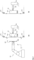
- FIG. 1 An example of a grinding device 100 known per se is shown in Figure 1 shown.
- the grinding device 100 is stationary and has a rotating grinding belt 102, which is guided over at least two rollers 101, 103. In this example it is assumed that the belt rotates clockwise.
- the sanding belt 102 is tensioned by a tensioning element 105 (tensioning roller), which is mounted in a linearly displaceable manner by a suitable bearing 130 (for example by means of a plain bearing).
- the components (rollers 101 and 103, clamping element 105) are connected to a frame 160 (eg a machine bed or a housing part) using one or more supports 401, 402, 403.
- the surface 200a of a workpiece 200 to be processed is pressed against the sanding belt 102 in the area of the first roller 101 while the sanding belt 102 is running.
- the contact force F K (grinding force) required for this can be set, for example, manually or with the help of a manipulator 150, which holds the workpiece.
- the manipulator 150 can be, for example, a standard industrial robot (with six degrees of freedom). Alternatively, however, another manually or mechanically operated clamping and/or pressing device can also be used as a manipulator.
- the contact force F K creates friction between the workpiece surface 200a and the Grinding belt 102 and material removal occurs.
- the main influencing factors for the machining result are the contact force F K per surface (support surface on which the sanding belt 102 and the surface of the workpiece 200a touch), hereinafter also referred to as contact pressure, and the rotational speed of the sanding belt 102. Since the contact surface is between the workpiece and grinding belt 102 generally does not change significantly during a grinding process, contact pressure and contact force F K are de facto proportional. In the area of corners and edges, the contact force (ie its target value) can be reduced accordingly due to the smaller contact surface.
- a correct setting (ie regulation) of the contact force F K is desirable throughout the entire machining process.
- Force control by the generally "rigid" manipulator proves to be difficult in known automated grinding devices, especially when placing the workpiece 200 on the grinding belt.
- transient disturbances (force peaks) in the contact force F K are very difficult to compensate for through control using conventional means. This is usually a result of the inertia of the moving parts of the manipulator 150 and limitations in the actuators (minimum dead time, maximum force or torque, etc.).
- Insufficient force control results in inhomogeneous micrographs with chatter marks. Chatter marks are surface irregularities caused by inadequate control of the contact force F K.
- the workpiece 200 is held and positioned by a manipulator 150.
- the manipulator 150 only requires a simple position control; the contact force control is implemented in the grinding machine 100 - as described below.
- Relatively inexpensive manipulators e.g. industrial robots
- the actuator 302 used for force control can be a simple linear actuator, for example an actuator with low static friction and passive compliance.
- Possible examples include pneumatic cylinders, air muscles, bellows cylinders, and electric direct drives (without gearboxes).
- a pneumatic cylinder is used as actuator 302.
- the actuator 302 does not act on the grinding machine 100 as a whole, but only on that roller of the grinding machine 100 that presses against the workpiece during operation (ie on the roller 101).
- the roller 101 is mounted on the frame 160 in a linearly displaceable manner (linear guide 140) (via the roller carrier 401).
- the actuator 302 acts between the roller carrier 401 and the frame 160.
- the actuator is mounted on the roller carrier 401 and on a further carrier 404, which is rigidly connected to the frame 160.
- the Roller 101 exerts an actuator force F A , which acts along the direction of movement (x-direction) of the linear guide 140. Due to the comparatively low mass of the first roller 101 (and the roller carrier 401), only small inertia forces occur on the actuator 302.
- the grinding device is in accordance with Fig. 2 constructed in the same way as the grinding device in the previous example Fig. 1 .
- the second role 103 is mounted immovably on the frame 160 via the (roller) carrier 403.
- immovable does not mean that the position of the roller 103 cannot be changed, for example to set a suitable tension in the sanding belt.
- the position of the roller 103 does not change during operation of the device (for example, during a grinding process).
- the roller 103 is driven (motor 104), whereas the roller 101 only serves as a deflection roller.
- the sanding belt 102 is guided around both rollers 101 and 103.
- a tensioning device can be provided for adjusting a pretension of the sanding belt.
- the tensioning device can, for example, have one or more tension rollers 105 which rest on the belt 102 and which can be moved approximately at right angles to the grinding belt 102 in order to tension the grinding belt 102.
- the tension rollers 105 are mounted on the roller carrier 402 with the aid of a linear guide 130, which in turn is rigidly connected to the frame 160.
- the pretension can be generated, for example, with the help of a spring which acts between the roller carrier 402 and the tension roller (or tension rollers) 105.
- the forces acting in the sanding belt 102 are in Fig. 2 shown as band forces F B1 (force in the upper part 102a of the band 102) and F B2 (force in the lower part 102b of the band 102), whereby both forces F B1 and F B2 each have a force component in the x direction (F B1,x or . F B2,x ) and have a force component in the y direction (F B1,y or F B1,y ).
- the resulting belt force F B,x acting on the roller 101 in the x direction also acts on the actuator 302 and thus against the actuator force F A.
- the band force F B, x must be known. This can either be measured (e.g. using a force sensor in the clamping device and the drive torque of the motor) or estimated using a mathematical model.
- actuator force F A and the resulting belt force F B,x in the effective direction (x direction) of actuator 302 are decoupled.
- An example of a suitable deflection of the sanding belt 102 is shown in Fig. 3 shown.
- FIG. 3 The example shown essentially corresponds to the previous example Fig. 2 , whereby two further deflection rollers 101a and 101b are arranged on the roller carrier 401 in addition to the deflection roller 101. Furthermore, two further deflection rollers 121a, 121b are provided, which are mounted immovably on the frame 160.
- the roller carrier 401 with the rollers 101, 101a and 101b is mounted on the frame 160 by means of the linear guide 140, the linear guide enabling the roller carrier 401 to be displaced in the horizontal direction (x direction) and blocking other degrees of freedom.
- the deflection rollers 101a and 101b as well as the deflection rollers 121a and 121b are arranged so that - at a nominal deflection x 0 (target deflection) of the actuator 302 - the resulting belt force F B 'acting on the roller carrier 401 is the actuator force F A (at least approximately) is at a right angle.
- the x component F B,x 'of the resulting belt force F B' is approximately zero, with the linear guide 140 allowing force transmission from the actuator 302 to the roller carrier 401 only in the x direction.
- Figure 4 shows the on a roll carrier 401 (e.g. from Fig. 3 ) acting forces in detail.
- Fig. 4c is a variant of Fig. 4a , in which the actuator force F A attacks exactly in the center of the roller carrier 401, so that all forces cancel out at the operating point and no torque acts on the roller carrier 4.
- Fig. 4a and Fig. 4b the relevant forces on the rollers 101, 101a, 101b mounted on the roller carrier 401 are shown again in detail.
- the rollers 101, 101a and 101b which are mounted displaceably in the x direction, as well as the sanding belt 102 and the workpiece 200 are shown.
- the position of the axes of rotation of the rollers 101, 101a and 101b relative to one another is fixed and does not change during operation.
- the actuator force F A and the contact force F K act on the rollers in the x direction (actuator and contact forces in other directions would be absorbed by the linear guide 140).
- Fig. 4a and Fig. 4b the relevant forces on the rollers 101, 101a, 101b mounted on the roller carrier 401 are shown again in detail.
- the actuator force F A and the contact force F K act on the rollers in the x direction (actuator and contact forces in other directions would be absorbed by the linear guide 140).
- the actuator 302 only acts on the roller carrier 401, which carries the deflection rollers 101, 101a, 101b, and not on the entire grinding device.
- the actuator force acts exactly at the center point C, so that the clamping forces F B1 ', F B2 ' and the friction force F R cancel each other out. In the same way, contact force F K and actuator force F A cancel each other out.
- Fig. 5 shows an alternative embodiment of the grinding device 100, which is also suitable for decoupling the actuator force F A and the belt forces F B1 , F B2 .
- the grinding device 100 is constructed in the same way as that in the previous example Fig. 4 .
- the linear guide 140 of the roller carrier 401 and the actuator 302 are compared to the example Fig. 4 rotated by 90 degrees.
- the frame 160 includes an arm 402 on which the roller carrier 401 is mounted (with the help of the linear guide 140).
- the actuator 302 acts in the vertical direction (x direction) between the arm 402 of the frame 160 and the roller carrier 401.
- the coordinate system is also rotated by 90 degrees compared to the previous example, so that the effective direction of the actuator 302 is the x- direction is. Additional deflection rollers are not essential in this exemplary embodiment necessary.
- the sanding belt 102 is only guided around the deflection roller 101 and the roller 103 (driven by the motor 104).
- a tensioning device with a tension roller 105 ensures the necessary pretension of the sanding belt 102.
- the belt forces acting on the displaceably mounted deflection roller are designated F B1 (force in the upper belt part) and F B2 (force in the lower belt part).
- the force components F B1,x and F B2,x in the x direction at least partially compensate each other (F B1,x >0 and F B2,x ⁇ 0), so that the resulting force component in the x direction F B1,x +F B2,x is negligibly small.
- the resulting force F B1,x +F B2,x is equal to zero and there is no reaction of the belt forces F B1 and F B2 on the actuator 302.
- Fig. 6a corresponds to the situation in Fig.
- the resulting belt force disappears in the x-direction
- ⁇ sin( ⁇ 2 ) and there is no reaction on the actuator 302 (for example because ⁇ 1 ⁇ 2 and
- Two deflection rollers 121a and 121b, which are firmly mounted on the frame 160, ensure that the angles ⁇ 1 and ⁇ 2 are equal to zero, so that the belt runs horizontally back and forth to the roller 101. Consequently, in this case, the resulting belt forces in the x direction are zero, provided that the factory return and thus the actuator 302 are at the operating point (x x 0 ).
- the previous example Fig. 3
- FIG. 7a shows devices which are not covered by the claims.
- Two rollers 101a and 101b are arranged on the roller carrier 401, on which the actuator 302 also acts.
- the belt 102 runs over the two rollers 101a, 101b essentially at right angles to the direction of action of the actuator 302.
- the workpiece 200 can be processed (eg ground or polished) between the rollers 101a, 101b; the tape can follow the contour of the workpiece 200 adjust.
- Fig. 7a constructed in the same way as the example Fig. 3 .
- Fig. 7b essentially corresponds to the previous example Fig.
- the carrier 401' (sliding carriage) instead has a sliding surface 101c along which the belt can slide essentially at right angles to the effective direction of the actuator 302.
- the band 102 runs essentially perpendicular to the effective direction of the actuator 302 at the operating point.
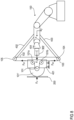
- the example according to Fig. 8 It is not the workpiece that is guided by the manipulator 150, but rather the grinding machine.
- the frame 160 (see e.g Fig. 3 ) is therefore part of the manipulator 150 or rigidly connected to it (its tool center point TCP).
- the workpiece 200 can be arranged on a fixed support (not shown).
- Two further deflection rollers 101a and 101b are arranged on a roller carrier 401 in addition to the deflection roller 101.
- two further deflection rollers 105 and 103 are provided, which are mounted on the manipulator 150 (a, frame 160) by means of the roller carriers 402 and 403, respectively.
- the roller 4 can be driven with the help of a motor.
- the motor (not explicitly shown) can also be mounted on the carrier 402.
- the roller 105 on the roller carrier 402 is designed as a tension roller.
- the roller carrier 401 with the rollers 101, 101a and 101b is similar to the example according to Fig. 3 slidably mounted on the manipulator, allowing the roller carrier 401 to be displaced in the x direction and blocking other degrees of freedom.
- the carrier 404 is also mounted on the manipulator 150.
- the actuator 302, which acts on the roller carrier 401, is arranged on the carrier 404.
- the tool with the frontmost roller 101 is a grinding wheel 101 '(or a other rotating tool).
- the belt runs essentially at right angles to the direction of action of the actuator, so that the belt forces F B1 ', F B2 ' are decoupled from the actuator force and there is no reaction from the belt forces F B1 '. ', F B2 ' takes place on the actuator 302.
- Figure 9 shows an example not covered by the claims, in which two rollers 101, 101a are arranged on an elongated roller carrier 401 at opposite ends of the roller carrier 401.
- the roller carrier is on the frame 160 (cf. Fig. 3 , in Fig. 9 not shown) stored slidably.
- Two further rollers 103 and 105 are also mounted on the frame (carriers 403 and 402), whereby the roller 105 can be driven by a motor (cf. Fig. 3 , in Fig. 9 not shown) and the other roller 103 can be part of a tensioning unit to tension the rotating belt 102.
- the tensioning unit can also be integrated in the drive (roller 105).
- the movable roller carrier 401 (slide) is arranged between the rollers 103 and 105;
- the belt running around the rollers 101, 103, 101a, 105 approximately forms a convex square in the cross-sectional view.
- the illustration makes it clear that the belt forces acting on the roller carrier 401 cancel each other out in the direction of action of the actuator 302, and no belt forces act back on the actuator 302, which acts on the roller carrier 401.
- the actuator presses the roller carrier 401 with a force F A and thus the roller 101 onto the workpiece.
- the contact force F K reaction force
- corresponds to the actuator force F A (F K -F A ).
- the workpiece is guided by a manipulator 150 and positioned so that the deflection x of the actuator 302 lies at a defined working point x 0 .
- the actuator 302 works purely in a force-controlled manner; the position is determined by the (position-controlled) manipulator 150. Small deviations from the operating point (e.g. due to shape and positional tolerances of the workpiece or due to limited positioning accuracy of the manipulator 150) do not lead to any significant change in the geometry of the device and the belt forces, so that the grinding force can always be specified by the force-controlled actuator 302.
- Fig. 10 shows an example of a control loop for regulating the contact force F K between the workpiece 200 and the grinding belt 102 on the deflection roller 101.
- the force measurement can take place directly via a force sensor integrated in the actuator 302 or coupled to it. In the case of a pneumatic actuator, however, the force measurement can also take place indirectly via the pressure p in the pneumatic actuator, taking into account the deflection x of the actuator 302.
- the actuator force F A (p, x) is a function of the pressure p in the actuator (e.g. in the pneumatic piston) and the deflection x of the actuator.
- an estimate or a separate measurement of the resulting belt force can be taken into account when measuring the contact force.
- F K,m -F A (p, x)-F B,x .
- the controller 301 can be, for example, a P controller, a PI controller, or a PID controller. However, other types of controllers can also be used.
Description
Die Erfindung bezieht sich auf eine Vorrichtung zur automatisierten spanenden oder glättenden Bearbeitung von Oberflächen von Werkstücken, beispielsweise zum Schleifen von Werkstückoberflächen.The invention relates to a device for the automated machining or smoothing of surfaces of workpieces, for example for grinding workpiece surfaces.
Die Endbearbeitung von Oberflächen in der Kleinserienproduktion wird in den meisten Fällen noch von Hand ausgeführt. Dies nimmt viel Zeit in Anspruch und muss von einem erfahrenen Facharbeiter durchgeführt werden. Dieser Arbeitsschritt ist umso aufwändiger, je hochwertiger die endgültige Oberfläche sein muss. Als Beispiel kann die Oberfläche einer PKW-Motorhaube angeführt werden, bei der die Anforderungen an die Qualität der Oberfläche verhältnismäßig hoch sind. Zur Herstellung einer derartigen Oberflächenqualität gibt es für die Kleinserie neben der Handarbeit mit einer (Hand-) Schleifmaschine keine adäquate Lösung. Die Schleifergebnisse von bekannten Schleifautomaten sind häufig mangelhaft oder benötigen lange Einstellzeiten oder Ein- und Auslaufbereiche, um zu vermeiden, dass Unregelmäßigkeiten im Schliffbild auf der endgültigen Oberfläche zu sehen sind. Diese Unregelmäßigkeiten entstehen aufgrund von Schwingungen im Schleifband oder einer zu trägen Regelung der Kontaktkraft. Die Kontaktkraft ist die Kraft, mit der das Schleifband auf die Werkstückoberfläche einwirkt. In der Publikation
Die der Erfindung zugrunde liegende Aufgabe besteht somit darin, eine Vorrichtung bereitzustellen, welche es ermöglicht, dass aufwendige Schleif- oder Polituraufgaben teil- oder vollautomatisiert mit verbesserter Qualität ausgeführt werden können.The object on which the invention is based is therefore to provide a device which enables complex grinding or polishing tasks to be carried out partially or fully automatically with improved quality.
Die genannte Aufgabe kann beispielsweise durch eine Vorrichtung gemäß Anspruch 1 oder durch ein Verfahren gemäß Anspruch 8 sowie durch ein System gemäß Anspruch 11 gelöst werden. Unterschiedliche Ausführungsbeispiele und Weiterentwicklungen sind Gegenstand der abhängigen Ansprüche.The stated object can be achieved, for example, by a device according to claim 1 or by a method according to claim 8 and by a system according to claim 11. Different embodiments and further developments are the subject of the dependent claims.
Es wird im Folgenden eine Vorrichtung zur Bearbeitung einer Oberfläche eines Werkstücks beschrieben. Gemäß einem Ausführungsbeispiel umfasst die Vorrichtung einen Rahmen und einen Rollenträger, an dem eine erste Rolle drehbar gelagert ist und der an dem Rahmen entlang einer ersten Richtung verschiebbar gelagert ist. Die Vorrichtung umfasst zumindest eine zweite Rolle, welche an dem Rahmen gelagert ist, sowie ein Band, das zumindest um die beiden Rollen geführt ist, und aufgrund dessen Spannung eine resultierende Bandkraft auf den Rollenträger wirkt, wobei die erste Rolle nur als Umlenkrolle dient. Die Vorrichtung umfasst weiter eine Spannrolle zum Einstellen einer Vorspannkraft im Band. Die Vorrichtung umfasst des Weiteren einen Aktor, der mechanisch mit dem Rahmen und dem Rollenträger derart gekoppelt ist, dass eine einstellbare Aktorkraft zwischen dem Rahmen und der ersten Rolle entlang der ersten Richtung wirkt. Das Band ist dabei mit Hilfe der zweiten Rolle - oder mit Hilfe der zweiten Rolle und weiterer Rollen - so geführt, dass die auf den Rollenträger wirkende resultierende Bandkraft bei einer Soll-Auslenkung des Aktors annähernd in einer zweiten Richtung wirkt, die orthogonal zur ersten Richtung ist. Der Aktor arbeitet rein kraftgeregelt.A device for processing a surface of a workpiece is described below. According to an exemplary embodiment, the device comprises a frame and a roller carrier on which a first roller is rotatably mounted and which is mounted on the frame so as to be displaceable along a first direction. The device comprises at least a second roller, which is mounted on the frame, and a belt which is guided at least around the two rollers, and due to the tension of which a resulting belt force acts on the roller carrier, the first roller only serving as a deflection roller. The device further comprises a tension roller for adjusting a pretensioning force in the band. The device further includes an actuator mechanically coupled to the frame and the roller carrier such that an adjustable actuator force acts between the frame and the first roller along the first direction. The band is guided with the help of the second roller - or with the help of the second roller and further rollers - in such a way that the resulting band force acting on the roller carrier acts approximately in a second direction, which is orthogonal to the first direction, when the actuator is deflected to a desired extent is. The actuator works purely force-controlled.
Des Weiteren wird ein Verfahren zur Oberflächenbearbeitung eines Werkstückes beschrieben. Gemäß einem Ausführungsbeispiel des Verfahrens wird dazu eine Vorrichtung verwendet, die einen Rahmen, einen Rollenträger, an dem eine erste Rolle drehbar gelagert ist und der an dem Rahmen entlang einer ersten Richtung verschiebbar gelagert ist, einen Aktor, der mechanisch mit dem Rahmen und dem Rollenträger gekoppelt ist, eine zweite Rolle, welche an dem Rahmen gelagert ist, sowie ein Band, das um die erste und die zweite Rolle geführt ist und das eine resultierende Bandkraft auf den Rollenträger ausübt, aufweist, wobei die erste Rolle nur als Umlenkrolle dient. Die Vorrichtung umfasst weiter eine Spannrolle zum Einstellen einer Vorspannkraft im Band. Das Verfahren umfasst dabei das Positionieren des Werkstücks an der ersten Rolle, das Messen einer Kontaktkraft zwischen der ersten Rolle und dem Werkstück, und das Einstellen einer Kontaktkraft zwischen der ersten Rolle und dem Werkstück, indem eine zwischen Rahmen und Aktor wirkende Kraft eingestellt wird. Beim Positionieren des Werkstücks wird dieses relativ zur Vorrichtung derart positioniert, dass die Auslenkung des Aktors seiner Soll-Auslenkung entspricht. Bei der Soll-Auslenkung wirkt die auf den Rollenträger wirkende resultierende Bandkraft annähernd in einer zweiten Richtung, die orthogonal zur ersten Richtung ist. Die Rückwirkung der Bandkraft auf den Aktor kann somit theoretisch auf Null reduziert werden. Der Aktor arbeitet rein kraftgeregelt.Furthermore, a method for surface processing of a workpiece is described. According to an exemplary embodiment of the method, a device is used for this purpose which has a frame, a roller carrier on which a first roller is rotatably mounted and which is mounted on the frame so as to be displaceable along a first direction, an actuator which is mechanically connected to the frame and the roller carrier is coupled, a second roller which is mounted on the frame, and a belt which is guided around the first and the second roller and which exerts a resulting belt force on the roller carrier, the first roller serving only as a deflection roller. The device further comprises a tension roller for adjusting a pretensioning force in the band. The method includes positioning the workpiece on the first roller, measuring a contact force between the first roller and the workpiece, and adjusting a contact force between the first roller and the workpiece by adjusting a force acting between the frame and the actuator. When positioning the workpiece, it is positioned relative to the device in such a way that the deflection of the actuator corresponds to its target deflection. At the target deflection, the resulting belt force acting on the roller carrier acts approximately in one second direction that is orthogonal to the first direction. The reaction of the belt force on the actuator can therefore theoretically be reduced to zero. The actuator works purely force-controlled.
Des Weiteren wird ein System zur robotergestützten Oberflächenbearbeitung von Werkstücken beschrieben. Gemäß einem Ausführungsbeispiel umfasst das System eine Bearbeitungsvorrichtung sowie einen Manipulator zur Positionierung des Werkstücks relativ zu der Bearbeitungsvorrichtung. Diese weist einen Rahmen auf sowie einen Rollenträger, an dem eine erste Rolle drehbar gelagert ist und der an dem Rahmen entlang einer ersten Richtung verschiebbar gelagert ist. Die Bearbeitungsvorrichtung umfasst zumindest eine zweite Rolle, welche an dem Rahmen gelagert ist, sowie ein Band, das zumindest um die beiden Rollen geführt ist, und aufgrund dessen Spannung eine resultierende Bandkraft auf den Rollenträger wirkt, wobei die erste Rolle nur als Umlenkrolle dient. Das System umfasst weiter eine Spannrolle zum Einstellen einer Vorspannkraft im Band. Die Bearbeitungsvorrichtung umfasst des Weiteren einen Aktor, der mechanisch mit dem Rahmen und dem Rollenträger derart gekoppelt ist, dass eine einstellbare Aktorkraft zwischen dem Rahmen und der ersten Rolle entlang der ersten Richtung wirkt. Das Band ist dabei mit Hilfe der zweiten Rolle - oder mit Hilfe der zweiten Rolle und weiterer Rollen - so geführt, dass die auf den Rollenträger wirkende resultierende Bandkraft bei einer Soll-Auslenkung des Aktors annähernd in einer zweiten Richtung wirkt, die orthogonal zur ersten Richtung ist. Der Aktor arbeitet rein kraftgeregelt arbeitet und eine Position des Werkstücks relativ zu der Bearbeitungsvorrichtung wird lediglich durch den Manipulator bestimmt.Furthermore, a system for robot-assisted surface processing of workpieces is described. According to one exemplary embodiment, the system comprises a processing device and a manipulator for positioning the workpiece relative to the processing device. This has a frame and a roller carrier on which a first roller is rotatably mounted and which is mounted on the frame so as to be displaceable along a first direction. The processing device comprises at least a second roller, which is mounted on the frame, and a belt which is guided at least around the two rollers, and due to the tension of which a resulting belt force acts on the roller carrier, the first roller only serving as a deflection roller. The system further includes a tension roller for adjusting a pre-tension force in the belt. The processing device further comprises an actuator that is mechanically coupled to the frame and the roller carrier such that an adjustable actuator force acts between the frame and the first roller along the first direction. The band is guided with the help of the second roller - or with the help of the second roller and further rollers - in such a way that the resulting band force acting on the roller carrier acts approximately in a second direction, which is orthogonal to the first direction, when the actuator is deflected to a desired extent is. The actuator works purely in a force-controlled manner and a position of the workpiece relative to the processing device is only determined by the manipulator.
Die Erfindung wird nachfolgend anhand von den in den Abbildungen dargestellten Beispielen näher erläutert. Die Darstellungen sind nicht zwangsläufig maßstabsgetreu und die Erfindung beschränkt sich nicht nur auf die dargestellten Aspekte. Vielmehr wird Wert darauf gelegt, die der Erfindung zugrunde liegenden Prinzipien darzustellen. In den Abbildungen zeigt:
-
Figur 1 zeigt eine Bandschleifvorrichtung gemäß einem nicht durch die Ansprüche abgedeckten Beispiel, bei der die Kontaktkraft zwischen Werkstück und Schleifband mit Hilfe eines Manipulators erzeugt wird. -
Figur 2 zeigt eine Bandschleifvorrichtung gemäß einem nicht durch die Ansprüche abgedeckten Beispiel mit nachgiebiger Lagerung einer ersten Rolle der Bandschleifvorrichtung. -
Figur 3 zeigt eine Bandschleifvorrichtung gemäß einem Ausführungsbeispiel der Erfindung, bei dem die erste Rolle um einen Rollensatz ergänzt worden ist. -
Figur 4 zeigt ein Detail der Vorrichtung ausFig. 3 zur besseren Darstellung der auf die Rollen wirkenden Kräfte im Arbeitspunkt (Fig. 4a und 4c ) und außerhalb des Arbeitspunktes (Fig. 4b ). -
Figur 5 zeigt ein weiteres Ausführungsbeispiel, bei dem die resultierende Zugkraft im Schleifband und die Kontaktkraft zwischen Werkstück und Schleifvorrichtung annähernd orthogonal zueinander sind. -
Figur 6a zeigt ein Detail der Vorrichtung ausFig. 5 zur besseren Darstellung der auf die Rollen wirkenden Kräfte undFigur 6b zeigt eine Alternative zuFig. 6a . -
Figur 7 zeigt ein weiteres Beispiel, das nicht durch die Ansprüche abgedeckt ist, als Alternative zum Beispiel ausFig. 3 . -
Figur 8 zeigt eine Variante, bei der nicht das Werkstück, sondern die Schleifvorrichtung von einem Manipulator geführt sind. -
Figur 9 zeigt ein alternatives Beispiel, das nicht durch die Ansprüche abgedeckt ist, zur Entkopplung von Bandkräften und Aktorkraft. -
Figur 10 zeigt ein Blockschaltbild betreffend die Regelung der Kontaktkraft in einer Vorrichtung gemäß den dargestellten Ausführungsbeispielen.
-
Figure 1 shows a belt grinding device according to an example not covered by the claims, in which the contact force between the workpiece and the grinding belt is generated with the aid of a manipulator. -
Figure 2 shows a belt grinding device according to an example not covered by the claims with flexible mounting of a first roller of the belt grinding device. -
Figure 3 shows a belt grinding device according to an embodiment of the invention, in which the first roller has been supplemented by a set of rollers. -
Figure 4 shows a detail of the deviceFig. 3 for a better representation of the forces acting on the rollers at the working point (Figs. 4a and 4c ) and outside the operating point (Fig. 4b ). -
Figure 5 shows a further exemplary embodiment in which the resulting tensile force in the grinding belt and the contact force between the workpiece and the grinding device are approximately orthogonal to one another. -
Figure 6a shows a detail of the deviceFig. 5 for a better representation of the forces acting on the rollers andFigure 6b shows an alternative toFig. 6a . -
Figure 7 shows another example, not covered by the claims, as an alternative to the exampleFig. 3 . -
Figure 8 shows a variant in which not the workpiece but the grinding device is guided by a manipulator. -
Figure 9 shows an alternative example, not covered by the claims, for decoupling band forces and actuator force. -
Figure 10 shows a block diagram relating to the control of the contact force in a device according to the exemplary embodiments shown.
In den Figuren bezeichnen gleiche Bezugszeichen gleiche oder ähnliche Komponenten mit jeweils gleicher oder ähnlicher Bedeutung.In the figures, the same reference numbers designate the same or similar components, each with the same or similar meaning.
Die hier beschriebenen Beispiele der Erfindung werden im Zusammenhang mit einer Bandschleifvorrichtung 100 beschrieben. Andere Anwendungen der Erfindung, zum Beispiel zur Oberflächenbeschichtung oder zum Polieren von Oberflächen sind ebenfalls möglich.The examples of the invention described here are described in connection with a
Die Endbearbeitung von technisch und optisch hochwertigen Oberflächen erfordert sehr hohe Genauigkeiten in der Fertigung. Die Einhaltung der geforderten Genauigkeit wird dadurch erschwert, dass sich der Zustand der Werkstückoberfläche 200a über den Bearbeitungszeitraum ändert. Deshalb ist die Endbearbeitung der Oberflächen in vielen Bereichen, insbesondere bei Kleinserien überwiegend Handarbeit. Ein Beispiel für eine an sich bekannte Schleifvorrichtung 100 ist in
Zur Bearbeitung wird die zu bearbeitende Oberfläche 200a eines Werkstücks 200 bei laufendem Schleifband 102 im Bereich der ersten Rolle 101 gegen das Schleifband 102 gedrückt. Die dazu nötige Kontaktkraft FK (Schleifkraft) kann z.B. manuell oder mit Hilfe eines Manipulators 150, welcher das Werkstück hält, eingestellt werden. Der Manipulator 150 kann z.B. ein Standard-Industrieroboter (mit sechs Freiheitsgraden) sein. Alternativ kann jedoch auch eine andere manuell oder maschinell betätigte Einspann- und/ oder Anpressvorrichtung als Manipulator verwendet werden. Durch die Kontaktkraft FK entsteht Reibung zwischen der Werkstückoberfläche 200a und dem Schleifband 102 und es kommt zum Materialabtrag. Wesentliche Einflussfaktoren für das Bearbeitungsergebnis sind die Kontaktkraft FK pro Fläche (Auflagefläche, an der sich Schleifband 102 und die Oberfläche des Werkstücks 200a berühren), im weiteren Verlauf auch als Anpressdruck bezeichnet, sowie die Umlaufgeschwindigkeit des Schleifbandes 102. Da sich die Auflagefläche zwischen Werkstück und Schleifband 102 in der Regel während eines Schleifvorgangs nicht wesentlich ändert, sind Anpressdruck und Kontaktkraft FK de facto proportional. Im Bereich von Ecken und Kanten kann aufgrund der geringeren Auflagefläche die Kontaktkraft (d.h. deren Sollwertvorgabe) entsprechend reduziert werden.For processing, the
Für ein gleichmäßiges Schleifergebnis ist eine korrekte Einstellung (d.h. eine Regelung) der Kontaktkraft FK während des gesamten Bearbeitungsvorganges wünschenswert. Eine Kraftregelung durch den im Allgemeinen "starren" Manipulator erweist sich bei bekannten automatisierten Schleifvorrichtungen vor allem beim Aufsetzen des Werkstücks 200 auf das Schleifband als schwierig. Ganz allgemein sind transiente Störungen (Kraftspitzen) in der Kontaktkraft FK mit herkömmlichen Mitteln durch Regelung nur sehr schwer zu kompensieren. Dies ist in der Regel eine Folge der Trägheit der beweglichen Teile des Manipulators 150 und von Einschränkungen bei den Aktoren (minimale Totzeit, maximale Kraft bzw. Drehmoment, etc). Eine unzureichende Kraftregelung hat inhomogene Schliffbilder mit Rattermarken als Folge. Rattermarken sind Oberflächenunebenheiten, die durch eine unzureichende Regelung der Kontaktkraft FK entstehen. In Bereichen, in denen (temporär) eine höhere Kontaktkraft FK wirkt, entstehen durch den höheren Materialabtrag Vertiefungen in der Werkstückoberfläche 200a. An den Stellen, an denen temporär eine geringere Kontaktkraft FK vorherrscht wird weniger Material abgetragen und es bleiben Erhöhungen zurück. Durch einen erfahrenen Facharbeiter können diese Ungenauigkeiten beim Schleifen von Hand ausgeglichen werden. Beim automatisierten Anpressen der Werkstückoberfläche 200a an das Schleifband 102, speziell mit Hilfe eines Manipulators 150, können diese Ungenauigkeiten nicht ohne weiteres ausgeglichen werden. Durch die hohe Trägheit des Manipulators 150 ist die schnelle Anpassung an die jeweils vorherrschende Schleifsituation mit großen zeitlichen Verzögerungen verbunden. Außerdem kann der Manipulator 150 in unterschiedlichem Maße um seine vordefinierte Sollposition schwingen, was zu einem ungleichmäßigen Schliffbild führen kann.For a uniform grinding result, a correct setting (ie regulation) of the contact force F K is desirable throughout the entire machining process. Force control by the generally "rigid" manipulator proves to be difficult in known automated grinding devices, especially when placing the
Statt das Werkstück 200 mit Hilfe eines Manipulators zu bewegen, ist es auch möglich, das Werkstück 200 einzuspannen und die Schleifmaschine beweglich zu lagern. In diesem Fall wäre der Aktor, mit dem die Schleifkraft geregelt wird, mit der Schleifmaschine gekoppelt, sodass die Schleifmaschine gegen das (stationäre) Werkstück drückt. Auch in diesem Fall besteht das Problem, dass die Masse der Schleifmaschine und damit deren Trägheit verhältnismäßig groß ist und folglich das gleiche Problem besteht wie bei der oben beschriebenen Variante.Instead of moving the
In dem in
Der Aktor 302 wirkt nicht auf die Schleifmaschine 100 als Ganzes, sondern nur auf jene Rolle der Schleifmaschine 100, die im Betrieb gegen das Werkstück drückt (d.h. auf die Rolle 101). Die Rolle 101 ist (über den Rollenträger 401) linear verschiebbar (Linearführung 140) an dem Rahmen 160 gelagert. Der Aktor 302 wirkt zwischen Rollenträger 401 und Rahmen 160. Im vorliegenden Beispiel ist der Aktor an dem Rollenträger 401 und an einem weiteren Träger 404 gelagert, welcher starr mit dem Rahmen 160 verbunden ist. Entsprechend der Ansteuerung des Aktors 302, wird auf die Rolle 101 eine Aktorkraft FA, die entlang der Bewegungsrichtung (x-Richtung) der Linearführung 140 wirkt, ausgeübt. Durch die vergleichsweise geringe Masse der ersten Rolle 101 (und des Rollenträgers 401) treten am Aktor 302 nur geringe Massenträgheitskräfte auf.The
Im Übrigen ist die Schleifvorrichtung gemäß
Die in dem Schleifband 102 wirkenden Kräfte sind in ![]()
![]()
Das in
In
Die an der verschiebbar gelagerten Umlenkrolle wirkenden Bandkräfte sind mit FB1 (Kraft im oberen Bandteil) und FB2 (Kraft im unteren Bandteil) bezeichnet. Die Kraftkomponenten FB1,x und FB2,x in x-Richtung kompensieren einander zumindest teilweise (FB1,x>0 und FB2,x<0), sodass die die resultierende Kraftkomponente in x-Richtung FB1,x+FB2,x vernachlässigbar klein ist. Bei geeigneter Auslegung der Schleifvorrichtung ist die resultierende Kraft FB1,x+FB2,x gleich null und es gibt keine Rückwirkung der Bandkräfte FB1 und FB2 auf den Aktor 302.
Die
Anders als bei den vorhergehenden Ausführungsbeispielen wird bei Beispiel gemäß
Der Rollenträger 401 mit den Rollen 101, 101a und 101b ist ähnlich im Beispiel gemäß
Gemäß
Die Kraftmessung (Kraftmesseinheit 303) kann direkt über einen im Aktor 302 integrierten oder mit diesem gekoppelten Kraftsensor erfolgen. Bei einem pneumatischen Aktor kann die Kraftmessung jedoch auch indirekt über den Druck p im pneumatischen Aktor unter Berücksichtigung der Auslenkung x des Aktors 302 erfolgen. Das heißt die Aktorkraft FA(p, x) ist eine Funktion von Druck p im Aktor (z.B. im Pneumatikkolben) und der Auslenkung x des Aktors. Aus der gemessenen Aktorkraft FA kann der gesuchte Messwert FK,m für die Kontaktkraft ermittelt werden. Bei einer Entkopplung zwischen resultierender Bandkraft FB und Aktorkraft FA gilt FK,m=-FA(p, x). Sofern keine vollständige Entkopplung zwischen Aktorkraft FA und resultierender Bandkraft FB,x in Wirkrichtung des Aktors 320 vorliegt, kann bei der Messung der Kontaktkraft eine Schätzung oder eine separate Messung der resultierenden Bandkraft berücksichtigt werden. Für den Messwert FK,m gilt in diesem Fall: FK,m=-FA(p, x)-FB,x. Aus dem Messwert FK,m für die Kontaktkraft und einem korrespondierenden Sollwert FK,s kann ein Regelfehler FE berechnet werden (FE=FK,s-FK,m), der dem Regler 301 eingangsseitig zugeführt ist. Der Regler 301 kann z.B. ein P-Regler, ein PI-Regler, oder ein PID-Regler. Jedoch können auch andere Reglertypen verwendet werden.The force measurement (force measuring unit 303) can take place directly via a force sensor integrated in the
Claims (12)
- A device (100) for machining a surface of a workpiece (200a), having:a frame (160);a roller support (401) on which a first roller (101) is rotatably mounted and which is slidably mounted on the frame (160) along a first direction (x);a second roller (103) which is mounted on the frame (160);a belt (102) which is guided around the two rollers (101, 103) and due to the tension of which a resulting belt force (FB, FB') acts on the roller support, wherein the first roller (101) only serves as a deflection roller; andan idler (105) for adjusting a biasing force in the belt (102) ;characterized byan actuator (302) which is mechanically coupled to the frame (160) and the roller support (401) such that an adjustable actuator force (FA) acts between the frame (160) and the first roller (101) along the first direction (x);wherein the belt is guided by means of the second roller (103) or by means of the second roller (103) and further rollers such that the resultant belt force (FB, FB') acting on the roller support (401) at a target deflection of the actuator (302) acts approximately in a second direction (y) which is orthogonal to the first direction (x), wherein the actuator (302) operates in a purely force-controlled manner.
- The device according to claim 1, further having:a force measuring device for direct or indirect measurement of a contact force (FK) between the first roller (101) and a workpiece (200), or between a rotating tool (101') connected to the first roller (101) and the workpiece (200), anda control unit which is adapted to adjust the actuator force (FA) such that the contact force (FK) corresponds to a predefinable setpoint value (FK,S).
- The device according to claim 2,wherein the actuator (302) is a pneumatic linear actuator, andwherein the force measuring device has a pressure sensor which is adapted to measure the air pressure (p) in the pneumatic linear actuator.
- The device according to any one of claims 1 to 3,
in which the first roller (101) is rotatably mounted on the roller support (401) about an axis of rotation, and the roller support (401) is displaceable along the first direction (x) relative to the frame (160) by means of a linear guide (140). - The device according to any one of claims 1 to 4,
wherein-at a target deflection of the actuator (302)-the belt (102) runs towards the roller support (401) and away from the roller support (401) approximately at a right angle to the first direction. - The device according to any one of claims 1 to 5, in whichthe first roller (101) is mounted on a first end of the roller support (401) and a further roller (101a) is mounted on a second end of the roller support (401) opposite the first end, andthe belt (102) is guided symmetrically around the first roller (101) and further roller at a nominal deflection (x0) of the actuator (302) such that the resulting belt force on the roller support (401) in the first direction is zero or negligibly small.
- The device according to any one of claims 1 to 6,in which the frame support has deflection rollers (101a, 101b) for deflecting the belt (102).wherein the deflection rollers (101a, 101b) are arranged such that, at a nominal deflection (x0) of the actuator (302), the belt runs towards the roller support (401) and away from the roller support (401) in a second direction (y) which is orthogonal to the first direction.
- A method for machining surfaces of a workpiece (200) by means of a device (100), having:a frame (160),a roller support (401) on which a first roller (101) is rotatably mounted and which is slidably mounted on the frame (160) along a first direction (x),a second roller (103) which is mounted on the frame (160),an actuator (302) which is mechanically coupled to the frame (160) and the roller support (401),a belt (102) which is guided at least around the two rollers (101, 103) and which exerts a resulting belt force (FB, FB') on the roller support (401), wherein the first roller (101) only serves as a deflection roller, andan idler (105) for adjusting a biasing force in the belt (102),wherein the method comprises:positioning the workpiece (200) on the first roller (101),measuring a contact force (FK) between the first roller (191) and the workpiece (200);adjusting a contact force (FK) between the first roller (101) and the workpiece (200) by adjusting a force acting between the frame (160) and the actuator (302), wherein the positioning of the workpiece (200) positions the same relative to the device (100) such that the deflection of the actuator (302) corresponds to its target deflection, at which the resulting belt force (FB, FB') acting on the roller support (401) acts approximately in a second direction (y) which is orthogonal to the first direction (x), wherein the actuator (302) operates in a purely force-controlled manner.
- The method according to claim 8, in which the retroactive effect of the resulting belt force (FB, FB') on the actuator at the target deflection is approximately zero.
- The method according to claim 8 or 9, in which the actuator is a pneumatic linear actuator, and the measuring of a contact force (FK) comprises measuring the pressure (p) in the pneumatic linear actuator.
- A system for robotic surface machining of workpieces, having:a machining device (100), anda manipulator (150) for positioning the workpiece relative to the machining device (100),wherein the machining device (100) has:a frame (160);a roller support (401) on which a first roller (101) is rotatably mounted and which is slidably mounted on the frame (160) along a first direction (x);at least one second roller (103) which is mounted on the frame (160);a belt (102) which is guided at least around the two rollers (101, 103) and due to the tension of which a resulting belt force (FB, FB') acts on the roller support, wherein the first roller (101) only serves as a deflection roller; andan idler (105) for adjusting a biasing force in the belt (102),characterized byan actuator (302) which is mechanically coupled to the frame (160) and the roller support (401) such that an adjustable actuator force (FA) acts between the frame (160) and the first roller (101) along the first direction (x);wherein the belt is guided by means of the second roller (103) or by means of the second roller (103) and further rollers such that the resultant belt force (FB, FB') acting on the roller support (401) at a target deflection of the actuator (302) acts approximately in a second direction (y) which is orthogonal to the first direction (x), wherein the actuator (302) operates in a purely force-controlled manner, and a position of the workpiece relative to the machining device (100) is only determined by the manipulator (150).
- The system according to claim 11,
in which the manipulator (150) positions the workpiece relative to the machining device (100) such that the deflection of the actuator (302) corresponds to its target deflection.
Applications Claiming Priority (2)
| Application Number | Priority Date | Filing Date | Title |
|---|---|---|---|
| DE102015106480.4A DE102015106480A1 (en) | 2015-04-27 | 2015-04-27 | Device for surface treatment |
| PCT/AT2016/050111 WO2016172751A1 (en) | 2015-04-27 | 2016-04-25 | Device for machining surfaces |
Publications (3)
| Publication Number | Publication Date |
|---|---|
| EP3288712A1 EP3288712A1 (en) | 2018-03-07 |
| EP3288712B1 true EP3288712B1 (en) | 2023-10-11 |
| EP3288712C0 EP3288712C0 (en) | 2023-10-11 |
Family
ID=56072142
Family Applications (1)
| Application Number | Title | Priority Date | Filing Date |
|---|---|---|---|
| EP16724583.6A Active EP3288712B1 (en) | 2015-04-27 | 2016-04-25 | Device for machining surfaces |
Country Status (7)
| Country | Link |
|---|---|
| US (1) | US10974362B2 (en) |
| EP (1) | EP3288712B1 (en) |
| JP (2) | JP7017934B2 (en) |
| KR (1) | KR102480548B1 (en) |
| CN (1) | CN107666985A (en) |
| DE (1) | DE102015106480A1 (en) |
| WO (1) | WO2016172751A1 (en) |
Families Citing this family (4)
| Publication number | Priority date | Publication date | Assignee | Title |
|---|---|---|---|---|
| KR101944958B1 (en) * | 2017-06-07 | 2019-02-07 | 주식회사 제이로보텍 | Grinder apparatus |
| DE102020111292A1 (en) | 2020-04-24 | 2021-10-28 | Ferrobotics Compliant Robot Technology Gmbh | QUICK CLAMPING SYSTEM FOR CONNECTING MACHINE TOOLS WITH A ROBOT |
| CN112077674A (en) * | 2020-09-08 | 2020-12-15 | 合肥江丰电子材料有限公司 | Polishing process for back plate in target assembly |
| CN112720188B (en) * | 2020-12-25 | 2022-12-06 | 邵武市泽诚机械有限公司 | Grinding machine |
Citations (1)
| Publication number | Priority date | Publication date | Assignee | Title |
|---|---|---|---|---|
| DE10013340A1 (en) * | 2000-03-17 | 2001-09-27 | Carat Robotic Innovation Gmbh | Belt grinding machine includes tension roller loaded by force element coupled functionally to displaceable workpiece contact element so that predeterminable contact pressure is set independent of position change of contact element |
Family Cites Families (18)
| Publication number | Priority date | Publication date | Assignee | Title |
|---|---|---|---|---|
| JPS6389263A (en) | 1986-10-02 | 1988-04-20 | Toshiba Corp | Belt grinder device |
| US4841683A (en) * | 1987-12-23 | 1989-06-27 | Williams Clarence W | Roll grinding system |
| DE4030158A1 (en) * | 1990-09-24 | 1992-03-26 | Hau Simex Gmbh | BELT GRINDING MACHINE |
| JP3138870B2 (en) * | 1991-07-31 | 2001-02-26 | ファロス ブラター アーゲー | A grinder for polishing the cylindrical or spherical surface of paper machine rolls |
| CH686350A5 (en) * | 1992-02-07 | 1996-03-15 | Sig Schweiz Industrieges | Belt sander. |
| JPH08108359A (en) * | 1994-10-07 | 1996-04-30 | Fuji Photo Film Co Ltd | Polishing device |
| JPH10549A (en) * | 1996-06-12 | 1998-01-06 | Nisshinbo Ind Inc | Polishing device |
| US6645349B1 (en) * | 1998-01-20 | 2003-11-11 | Valmet Corporation | Method and device for conditioning of a roll, in particular of a roll in a paper machine or in a paper finishing device |
| DE19825698B4 (en) * | 1998-06-09 | 2005-07-21 | SHL Seelmann, Häring und Lehr Automatisierungstechnik GmbH | belt sander |
| KR20020034408A (en) * | 2000-11-01 | 2002-05-09 | 이구택 | Apparatus for correcting track of grinding belt |
| US6561870B2 (en) * | 2001-03-30 | 2003-05-13 | Lam Research Corporation | Adjustable force applying air platen and spindle system, and methods for using the same |
| JP2002301659A (en) | 2001-04-03 | 2002-10-15 | Kawasaki Heavy Ind Ltd | Automatic finish method and device |
| JP2003220546A (en) | 2002-01-24 | 2003-08-05 | Soken Kogyo Kk | Belt type polishing device |
| JP2009016759A (en) | 2007-07-09 | 2009-01-22 | Nihon Micro Coating Co Ltd | Device for polishing semiconductor wafer end face and polishing head used for the same |
| DE102012005439A1 (en) * | 2012-03-20 | 2013-09-26 | Texmag Gmbh Vertriebsgesellschaft | Device for influencing a running web |
| CN203779279U (en) * | 2013-12-07 | 2014-08-20 | 泸州职业技术学院 | Self-adaptation pressure mechanical arm polishing device |
| CN103692317B (en) * | 2013-12-10 | 2017-01-25 | 深圳先进技术研究院 | Belt grinder with force feedback function |
| ES2616797T3 (en) * | 2014-07-17 | 2017-06-14 | Franke Water Systems Ag | Procedure for driving a belt grinding device |
-
2015
- 2015-04-27 DE DE102015106480.4A patent/DE102015106480A1/en active Pending
-
2016
- 2016-04-25 JP JP2017556218A patent/JP7017934B2/en active Active
- 2016-04-25 KR KR1020177032399A patent/KR102480548B1/en active IP Right Grant
- 2016-04-25 CN CN201680030814.7A patent/CN107666985A/en active Pending
- 2016-04-25 WO PCT/AT2016/050111 patent/WO2016172751A1/en active Application Filing
- 2016-04-25 US US15/569,704 patent/US10974362B2/en active Active
- 2016-04-25 EP EP16724583.6A patent/EP3288712B1/en active Active
-
2021
- 2021-10-28 JP JP2021176697A patent/JP2022017427A/en active Pending
Patent Citations (1)
| Publication number | Priority date | Publication date | Assignee | Title |
|---|---|---|---|---|
| DE10013340A1 (en) * | 2000-03-17 | 2001-09-27 | Carat Robotic Innovation Gmbh | Belt grinding machine includes tension roller loaded by force element coupled functionally to displaceable workpiece contact element so that predeterminable contact pressure is set independent of position change of contact element |
Also Published As
| Publication number | Publication date |
|---|---|
| JP7017934B2 (en) | 2022-02-09 |
| JP2022017427A (en) | 2022-01-25 |
| JP2018516764A (en) | 2018-06-28 |
| KR102480548B1 (en) | 2022-12-22 |
| CN107666985A (en) | 2018-02-06 |
| US10974362B2 (en) | 2021-04-13 |
| DE102015106480A1 (en) | 2016-10-27 |
| WO2016172751A1 (en) | 2016-11-03 |
| KR20170140261A (en) | 2017-12-20 |
| EP3288712C0 (en) | 2023-10-11 |
| US20180126512A1 (en) | 2018-05-10 |
| EP3288712A1 (en) | 2018-03-07 |
Similar Documents
| Publication | Publication Date | Title |
|---|---|---|
| EP3439836B1 (en) | Robot-aided grinding apparatus | |
| EP3288712B1 (en) | Device for machining surfaces | |
| EP3325214B1 (en) | Machine tool for robot-assisted surface finishing | |
| DE102016106141A1 (en) | Change station for automatic change of abrasive | |
| DE102015104164B4 (en) | Method and device for robot-assisted surface treatment | |
| DE102015007132B4 (en) | Motor controller | |
| EP3765239B1 (en) | Rotational speed control in robot-assisted grinding | |
| DE102012222586A1 (en) | machine tool | |
| DE102015119589B4 (en) | Device and method for robotic roller hemming | |
| EP2834024A1 (en) | Robot-controlled shaping tool and shaping process | |
| EP2919081B1 (en) | Processing machine taking into account position errors in collision checking | |
| EP3159103A1 (en) | Method for operating the grinding device and grinding device | |
| DE102020113098A1 (en) | WORKPIECE TURNING DEVICE AND ROBOT SYSTEM | |
| DE102013202332B4 (en) | Device for the automatic machining of workpieces | |
| DE102019115562A1 (en) | COMPENSATION OF POSITION TOLERANCES DURING ROBOT-ASSISTED SURFACE MACHINING | |
| DE102020110492A1 (en) | DEVICE FOR ROBOTIC PROCESSING OF SURFACES | |
| EP2623257B1 (en) | Position compensation device in a machine tool | |
| EP2852472B1 (en) | Method for grinding workpieces, in particular for centring grinding of workpieces such as optical lenses | |
| EP3999277B1 (en) | Device and method for automatically removing grinding wheels | |
| DE102015113890A1 (en) | Machine tool with workpiece position and weight-dependent deflection compensation | |
| DE102019101579A1 (en) | ROBOT-BASED GRINDING DEVICE WITH INTEGRATED MAINTENANCE UNIT | |
| DE102022125510A1 (en) | Processing device and method for processing workpieces | |
| DE10239570B3 (en) | Method for calibrating a control valve with zero cut piston for a machine with a hydraulic drive, in particular for manipulators | |
| CH715886A2 (en) | Method for dressing a grinding tool by means of a machine tool. | |
| DE102006020681A1 (en) | Work piece positioning device, has linear drives adjusting length of three legs, and measuring system configured to measure position measured values of local measuring points at table top |
Legal Events
| Date | Code | Title | Description |
|---|---|---|---|
| STAA | Information on the status of an ep patent application or granted ep patent |
Free format text: STATUS: THE INTERNATIONAL PUBLICATION HAS BEEN MADE |
|
| PUAI | Public reference made under article 153(3) epc to a published international application that has entered the european phase |
Free format text: ORIGINAL CODE: 0009012 |
|
| STAA | Information on the status of an ep patent application or granted ep patent |
Free format text: STATUS: REQUEST FOR EXAMINATION WAS MADE |
|
| 17P | Request for examination filed |
Effective date: 20171122 |
|
| AK | Designated contracting states |
Kind code of ref document: A1 Designated state(s): AL AT BE BG CH CY CZ DE DK EE ES FI FR GB GR HR HU IE IS IT LI LT LU LV MC MK MT NL NO PL PT RO RS SE SI SK SM TR |
|
| AX | Request for extension of the european patent |
Extension state: BA ME |
|
| DAV | Request for validation of the european patent (deleted) | ||
| DAX | Request for extension of the european patent (deleted) | ||
| STAA | Information on the status of an ep patent application or granted ep patent |
Free format text: STATUS: EXAMINATION IS IN PROGRESS |
|
| 17Q | First examination report despatched |
Effective date: 20210531 |
|
| STAA | Information on the status of an ep patent application or granted ep patent |
Free format text: STATUS: EXAMINATION IS IN PROGRESS |
|
| GRAP | Despatch of communication of intention to grant a patent |
Free format text: ORIGINAL CODE: EPIDOSNIGR1 |
|
| STAA | Information on the status of an ep patent application or granted ep patent |
Free format text: STATUS: GRANT OF PATENT IS INTENDED |
|
| INTG | Intention to grant announced |
Effective date: 20230726 |
|
| GRAS | Grant fee paid |
Free format text: ORIGINAL CODE: EPIDOSNIGR3 |
|
| GRAA | (expected) grant |
Free format text: ORIGINAL CODE: 0009210 |
|
| STAA | Information on the status of an ep patent application or granted ep patent |
Free format text: STATUS: THE PATENT HAS BEEN GRANTED |
|
| AK | Designated contracting states |
Kind code of ref document: B1 Designated state(s): AL AT BE BG CH CY CZ DE DK EE ES FI FR GB GR HR HU IE IS IT LI LT LU LV MC MK MT NL NO PL PT RO RS SE SI SK SM TR |
|
| REG | Reference to a national code |
Ref country code: GB Ref legal event code: FG4D Free format text: NOT ENGLISH |
|
| REG | Reference to a national code |
Ref country code: CH Ref legal event code: EP |
|
| REG | Reference to a national code |
Ref country code: DE Ref legal event code: R096 Ref document number: 502016016149 Country of ref document: DE |
|
| REG | Reference to a national code |
Ref country code: IE Ref legal event code: FG4D Free format text: LANGUAGE OF EP DOCUMENT: GERMAN |
|
| U01 | Request for unitary effect filed |
Effective date: 20231011 |
|
| U07 | Unitary effect registered |
Designated state(s): AT BE BG DE DK EE FI FR IT LT LU LV MT NL PT SE SI Effective date: 20231026 |
|
| PG25 | Lapsed in a contracting state [announced via postgrant information from national office to epo] |
Ref country code: GR Free format text: LAPSE BECAUSE OF FAILURE TO SUBMIT A TRANSLATION OF THE DESCRIPTION OR TO PAY THE FEE WITHIN THE PRESCRIBED TIME-LIMIT Effective date: 20240112 |
|
| PG25 | Lapsed in a contracting state [announced via postgrant information from national office to epo] |
Ref country code: IS Free format text: LAPSE BECAUSE OF FAILURE TO SUBMIT A TRANSLATION OF THE DESCRIPTION OR TO PAY THE FEE WITHIN THE PRESCRIBED TIME-LIMIT Effective date: 20240211 |
|
| U20 | Renewal fee paid [unitary effect] |
Year of fee payment: 9 Effective date: 20240319 |