EP3480387B1 - Regenwassersammler - Google Patents
Regenwassersammler Download PDFInfo
- Publication number
- EP3480387B1 EP3480387B1 EP18202449.7A EP18202449A EP3480387B1 EP 3480387 B1 EP3480387 B1 EP 3480387B1 EP 18202449 A EP18202449 A EP 18202449A EP 3480387 B1 EP3480387 B1 EP 3480387B1
- Authority
- EP
- European Patent Office
- Prior art keywords
- rainwater collector
- collector according
- clamping ring
- section
- curvature
- Prior art date
- Legal status (The legal status is an assumption and is not a legal conclusion. Google has not performed a legal analysis and makes no representation as to the accuracy of the status listed.)
- Active
Links
Images






Classifications
-
- E—FIXED CONSTRUCTIONS
- E04—BUILDING
- E04D—ROOF COVERINGS; SKY-LIGHTS; GUTTERS; ROOF-WORKING TOOLS
- E04D13/00—Special arrangements or devices in connection with roof coverings; Protection against birds; Roof drainage ; Sky-lights
- E04D13/04—Roof drainage; Drainage fittings in flat roofs, balconies or the like
- E04D13/0404—Drainage on the roof surface
- E04D13/0409—Drainage outlets, e.g. gullies
-
- E—FIXED CONSTRUCTIONS
- E04—BUILDING
- E04D—ROOF COVERINGS; SKY-LIGHTS; GUTTERS; ROOF-WORKING TOOLS
- E04D13/00—Special arrangements or devices in connection with roof coverings; Protection against birds; Roof drainage ; Sky-lights
- E04D13/04—Roof drainage; Drainage fittings in flat roofs, balconies or the like
- E04D13/0404—Drainage on the roof surface
- E04D13/0409—Drainage outlets, e.g. gullies
- E04D2013/0413—Strainers for drainage outlets
Definitions
- the invention relates to a rainwater collector, in particular for a flat roof, with a water inlet opening arranged at the top, a smaller diameter water outlet opening arranged at the bottom and an intermediate section, which is rotationally symmetrical with respect to a vertical axis, the inner wall of which rises along a top inclined flat to a horizontal plane and at a distance below extends from the horizontal plane, tapering steeply into an inner cylinder jacket surface which extends around the vertical axis and extends in a contour line extending in a vertical plane spanned by the vertical axis.
- Rainwater collectors are used on flat roofs. They have an upper region which extends in a horizontal plane and which is adjoined by a rotationally symmetrical intermediate region which merges into a cylinder section spaced apart from the horizontal plane. Such a rainwater collector is from the WO 99/51834 previously known.
- the intermediate section has a rounded contour line and ribs which are intended to set the water flowing into the water inlet opening in a circular motion.
- a flat roof rain collector is known in which the inlet area forms a hyperbolic flow channel. This is to avoid the accumulation of backwater.
- the flow channel has several sections of curvature. A first to the The curvature section adjoining the horizontal plane is formed by a roof film drawn into the drain funnel. The course of curvature of the first curvature section is predetermined by a base body. An adjoining second curvature section is formed by a clamping ring.
- Rainwater collectors for flat roofs are also known from EP 0 146 561 , EP 0502493 B1 and the WO2010 / 103371 A1 .
- the latter also has a leaf trap.
- the invention has for its object to optimize a rainwater collector of the generic type hydromechanically.
- the contour line is designed in such a way that there is neither a backflow nor a stall when the water runs off.
- the contour line is designed such that the vertical component of the speed of the water acted upon from above by pressure from an upper water column and downwards by suction from a lower water column is greater than the radial component of the water speed in each volume region of the intermediate region.
- a second aspect of the invention relates to a preferred constructive embodiment of a hydromechanically optimized flat roof drain, it being essential that the above-mentioned contour line preferably has three curvature sections which follow one another in the radial direction and which can be inclined differently with respect to the vertical axis, but can also be curved to different extents.
- the rainwater collector has a base body which has a horizontal section which lies in the horizontal plane and which is covered by a roofing membrane, for example a roofing membrane or a sealing film.
- the horizontal section running in the horizontal plane is followed by an annular first curvature section along a circular line Surface is formed by the waterproofing membrane or roofing membrane lying on the base body.
- a radially adjoining second curvature section which is more inclined with respect to the vertical axis, is formed by a clamping ring, which clamps an opening edge region of the sealing membrane between itself and the base body.
- the clamping ring extends over the edge of the opening and continues into a cylinder section which is in a neck of the base body.
- the cylinder section of the clamping ring preferably has an external thread which is screwed into an internal thread of the neck.
- the third curvature section which adjoins the second curvature section, and is more inclined with respect to the vertical axis than the second curvature section is formed by a support ring of a leaf trap body.
- the third curvature section merges into an inner cylinder surface, which is formed by a cylindrical section of the leaf trap body.
- the radially outer edge of the clamping ring extends at an acute angle and, in the installed state, lies in a plane that runs parallel to the horizontal plane, so that it only forms an insignificant kink between the first curved section and the second curved section.
- the radially inner edge of the second curvature section is essentially flush with the radially outer edge of the third curvature section.
- the leaf trap body preferably has leaf trap webs that extend upward from the support ring of the leaf trap body.
- the leaf guard webs preferably extend obliquely in the direction of the axis of the cylinder sections and open into a cover section in which the leaf guard webs are connected to one another.
- the leaf traps have an elongated cross-section. They are thus designed as flat bodies, the longitudinal axes of the cross-sectional areas running in the radial direction.
- the wall thickness of the leaf traps is less than the distance between two leaf traps in the circumferential direction.
- the clamping ring preferably has guide ribs in the second curvature section. The guide ribs extend in the radial direction from the radially inner edge of the second Curvature section in which the second curvature section merges into the inflow surface until immediately adjacent to the radially inner edge of the second curvature section.
- the guide ribs which are aligned in the radial direction with the leaf traps, force the water flowing into the rain collector into a radial flow.
- the acceleration forces are such that the vertical component of the speed of the water acted upon from above by pressure from an upper water column and downwards by suction from a lower water column is greater than the radial component of the water speed in each volume region of the intermediate region. This dimensioning avoids eddies and build-up effects.
- the leaf trap body is connected to the clamping ring with a latching tongue.
- a latching tongue adjoins the supporting ring, which has a latching projection which engages in a latching niche of the clamping ring.
- An outlet pipe is screwed below the clamping ring with an external thread into the internal thread of the neck of the base body.
- the connecting pipe can have a reducing section in which the inside diameter of the connecting pipe decreases.
- the upper section of the connecting pipe can have a diameter of 160 mm, for example, so that the pipe diameter in the reducing section can be reduced to the usual diameters of 150 mm, 125 mm, 100 mm, 70 mm, 50 mm.
- the rainwater collector shown in the drawings is intended for use on flat roofs and is optimized hydromechanically with regard to its drainage capacity. It is also easy to install and requires little maintenance.
- the rainwater collector has a base body 1 made of plastic, which has a round, essentially angular basic shape in the exemplary embodiment. In the periphery, it forms a horizontal section 2, on which a roofing membrane, sealing film or the like can be placed.
- the horizontal section 2 is followed by a first curved section 4 along a circular boundary line, which is the start of a funnel-shaped depression which opens into a connecting pipe 35.
- the first curvature section 4 is followed in a flat arrangement by the roofing membrane or sealing film, which, with its section 33 adjoining a circular opening edge 34, is clamped between a sealing ring 6 lying in an annular groove 5 of the base body 1 and a clamping ring 12.
- the opening edge 34 of the roofing membrane 30 or sealing film is located in a free space 7 between the base body 1 and the clamping ring 12.
- a cylindrical section of the basic body 1, which forms a neck 8 extends below a curved section of the basic body 1.
- the outer wall of the neck 8 has ribs 11 in the form of an external thread.
- the inner wall of the neck 8 has an internal thread 9.
- the kink in which the first curvature section 4 merges into the inflow surface 15 is greater than 120 °.
- the kink in which the inflow surface 15 merges into the second curvature section 13 is also greater than 120 °.
- the second curvature section 13 is divided into individual circumferential fields by a plurality of guide ribs 19 extending in the radial direction.
- the second curvature section 13, like the first curvature section 4, is curved in the vertical direction and has an inclination to the vertical axis A, the inclination of the first curvature section 4 being less than the inclination of the second curvature section 13.
- a leaf trap body 20 which has a support ring 21, from which flat leaf trap webs 22 project upwards.
- the leaf traps 22 have an elongated cross section, the longitudinal axis of the cross-sectional areas extending in the radial direction.
- the upper ends of the leaf traps 22 are connected to one another by means of a head piece.
- the guide ribs 19 are in radial alignment with the leaf traps 22.
- the clamping ring 12 forms a recess 16 in which the support ring 21 of the leaf trap body 20 is received, so that the second curvature section 13 merges into the third curvature section 23, which is formed by the support ring 21 and which is more inclined with respect to the vertical axis A than the second curvature section 13.
- the leaf trap webs 22 extend in the radial direction over the entire radial extent of the third curvature section 23, which on its radial inner side extends into a cylinder jacket surface section 24 passes.
- the cylindrical jacket surface section 41 of the clamping ring 12 ends at an edge 17 and runs flush with the cylinder surface of a connecting pipe 35, which is screwed into the internal thread 9 from below with an external thread 36, a sealing ring being located in the region of an edge 10 of the neck 8 of the base body 1 37 extends.
- three latching tongues 26 project downwards in the axial direction in a uniform circumferential distribution and engage in latching niches 27 of the cylinder section 41 of the clamping ring 12.
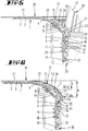
- the Figure 6 shows schematically a contour line L of the intermediate area between a horizontal section 31 of the roofing membrane 30 or sealing film and the cylinder section 41 or 24.
- the constants C and K are preferably in the range from 0.1 to 2.
- Graph A is a preferred contour line profile. In the case of rotationally symmetrical intermediate regions in which the contour line L forming in a longitudinal section is one of those in FIGS Figures 17 has run shown, the drainage performance is optimized.
- the contour line L runs essentially free of kinks from the top to the bottom and is curved in such a way that water dammed up vertically above the water inlet opening flows into a vertical flow through a downpipe adjoining the water outlet opening without a flow stall.
- the vertical component of the speed of the water which is acted upon from above by pressure from an upper water column and downwards by suction from a lower water column is preferably greater than the radial component of the water speed in each volume region of the intermediate region. This means that hardly any stall occurs and there is no backflow.
- the contour line L is preferably not interrupted and is also not disturbed by transverse ribs or the like.
- the guide ribs 19 arranged in front of the leaf trap webs 22 also reduce the formation of eddies, so that, in contrast to the prior art, an essentially radial / axial flow is formed.
- ⁇ b> ⁇ u> List of reference symbols ⁇ /u> ⁇ /b> 1 Basic body 26 Locking tongue 2nd horizontal section 27th Rest niche 3rd Contact surface 28 Recess 4th first section of curvature 29 head Start 5 Ring groove 30th roofing membrane 6 Sealing ring 31 horizontal section 7 free space 32 curved section 8th neck 33 pinched section 9 inner thread 34 Opening edge 10th Edge 35 Connecting pipe 11 Rib / external thread 36 External thread 12th Clamping ring 37 Sealing ring 13 second section of curvature 38 Vapor barrier 14 External thread 39 Reduction section 15 Inflow surface 40 cuff 16 niche 41 Cylinder section 17th Edge 18th free space 19th Leading rib A Vertical axis 20th Leaf trap H height 21st Support ring L Contour line 22 Leaf trap 23 third section of curvature 24th Cylinder
Landscapes
- Engineering & Computer Science (AREA)
- Architecture (AREA)
- Civil Engineering (AREA)
- Structural Engineering (AREA)
- Sewage (AREA)
- Tents Or Canopies (AREA)
Description
- Die Erfindung betrifft einen Regenwassersammler, insbesondere für ein Flachdach, mit einer oben angeordneten Wassereinlauföffnung, einer unten angeordneten durchmesserkleineren Wasseraustrittsöffnung und einem dazwischenliegenden, bezogen auf eine Vertikalachse rotationssymmetrischen Zwischenabschnitt, dessen Innenwandung sich entlang einer oben flach geneigt zu einer Horizontalebene entspringenden und unten in einem Abstand von der Horizontalebene, steil auslaufend in eine sich um die Vertikalachse erstreckenden inneren Zylindermantelfläche auslaufend verlaufenden, sich in einer von der Vertikalachse aufgespannten Vertikalebene erstreckenden Konturlinie erstreckt.
- Regenwassersammler werden an Flachdächern verwendet. Sie besitzen einen sich in einer Horizontalebene erstreckenden oberen Bereich, an dem sich ein rotationssymmetrischer Zwischenbereich anschließt, der in einen in einem Abstand von der Horizontalebene beabstandeten Zylinderabschnitt übergeht. Ein derartiger Regenwassersammler ist aus der
WO 99/51834 - Aus der
DE 88 04 040 U1 ist ein Flachdach-Regensammler vorbekannt, bei dem der Einlaufbereich einen hyperbelartig ausgebildeten Strömungskanal ausbildet. Damit soll das Ansammeln von Stauwasser vermieden werden. Der Strömungskanal weist mehrere Krümmungsabschnitte auf. Ein erster, an die Horizontalebene angrenzender Krümmungsabschnitt wird von einer in den Ablauftrichter eingezogenen Dachfolie ausgebildet. Der Krümmungsverlauf des ersten Krümmungsabschnitts wird dabei von einem Grundkörper vorgegeben. Ein sich daran anschließender zweiter Krümmungsabschnitt wird von einem Klemmring ausgebildet. - Regenwassersammler für Flachdächer sind darüber hinaus auch bekannt aus
EP 0 146 561 ,EP 0502493 B1 und derWO2010/103371 A1 . Letztere weist auch ein Laubfanggitter auf. - Der Erfindung liegt die Aufgabe zugrunde, einen Regenwassersammler der gattungsgemäßen Art hydromechanisch zu optimieren.
- Gelöst wird die Aufgabe durch die in den Ansprüchen angegebene Erfindung, wobei die Unteransprüche nicht nur vorteilhafte Weiterbildungen der nebengeordneten Ansprüche, sondern auch eigenständige Lösungen der Aufgabe darstellen.
- Zunächst und im Wesentlichen wird die Konturlinie derartig gestaltet, dass es beim Wasserabfluss weder zu einem Rückstau, noch zu einem Strömungsabriss kommt. Es ist insbesondere vorgesehen, dass die Konturlinie so gestaltet ist, dass die Vertikalkomponente der Geschwindigkeit des von oben durch Druck einer oberen Wassersäule und nach unten durch Sog einer unteren Wassersäule beaufschlagte Wasser in jedem Volumenbereich des Zwischenbereichs größer ist als die Radialkomponente der Wassergeschwindigkeit. Eine Berechnung der idealen Konturlinie unter Zuhilfenahme der Torricelli' schen Ausflussgleichung und der Kontinuitätsgleichung führt zu einer überraschend einfachen Funktion, nach dessen Graphen die Konturlinie verlaufen muss, damit der Wasserablauf optimiert ist. Die diesbezügliche Funktion


- Ein zweiter Aspekt der Erfindung betrifft eine bevorzugte konstruktive Ausgestaltung eines hydromechanisch optimierten Flachdachablaufs, wobei wesentlich ist, dass bevorzugt die oben genannte Konturlinie drei sich in Radialrichtung hintereinander anschließende Krümmungsabschnitte aufweist, die unterschiedlich stark gegenüber der Vertikalachse geneigt, aber auch unterschiedlich stark gekrümmt sein können. Erfindungsgemäß besitzt der Regenwassersammler einen Grundkörper, der einen Horizontalabschnitt aufweist, der in der Horizontalebene liegt und der von einer Dachbahn, bspw. einer Dachunterspannbahn oder einer Abdichtfolie, überdeckt ist. An den in der Horizontalebene verlaufenden Horizontalabschnitt schließt sich entlang einer kreisförmigen Line ein kreisringförmiger erster Krümmungsabschnitt an, dessen Oberfläche von der auf dem Grundkörper aufliegenden Dichtungsbahn bzw. Dachunterspannbahn ausgebildet ist. Ein sich radial daran anschließender zweiter Krümmungsabschnitt, der stärker gegenüber der Vertikalachse geneigt ist, wird von einem Klemmring ausgebildet, der zwischen sich und dem Grundkörper einen Öffnungsrandbereich der Dichtungsbahn einklemmt. Der Klemmring überfängt den Rand der Öffnung und setzt sich in einen Zylinderabschnitt fort, der in einem Hals des Grundkörpers steckt. Der Zylinderabschnitt des Klemmringes besitzt bevorzugt ein Außengewinde, das in ein Innengewinde des Halses eingeschraubt ist. Der dritte Krümmungsabschnitt, der sich an den zweiten Krümmungsabschnitt anschließt, und stärker gegenüber der Vertikalachse geneigt ist, als der zweite Krümmungsabschnitt wird von einem Tragring eines Laubfangkörpers ausgebildet. Der dritte Krümmungsabschnitt geht in eine Zylinderinnenmantelfläche über, die von einem Zylinderabschnitt des Laubfangkörpers gebildet ist. Die radial äußere Randkante des Klemmrings verläuft spitzwinklig aus und liegt im eingebauten Zustand in einer Ebene, die parallel zur Horizontalebene verläuft, so dass sie zwischen dem ersten Krümmungsabschnitt und dem zweiten Krümmungsabschnitt nur eine unwesentliche Knickstelle ausbildet. Der radial innere Rand des zweiten Krümmungsabschnittes schließt sich im Wesentlichen bündig an den radial äußeren Rand des dritten Krümmungsabschnittes an. Der Laubfangkörper besitzt bevorzugt Laubfangstege, die sich vom Tragring des Laubfangkörpers nach oben erstrecken. Bevorzugt erstrecken sich die Laubfangstege schräg in Richtung auf die Achse der Zylinderabschnitte nach oben und münden in einen Deckelabschnitt, in dem die Laubfangstege miteinander verbunden sind. Die Laubfangstege besitzen einen länglichen Querschnitt. Sie sind somit als Flachkörper ausgebildet, wobei die Längsachsen der Querschnittsflächen in Radialrichtung verlaufen. Die Wandstärke der Laubfangstege ist geringer als der Abstand zweier Laubfangstege in Umfangsrichtung. Der Klemmring weist im zweiten Krümmungsabschnitt bevorzugt Leit-Rippen aus. Die Leit-Rippen erstrecken sich in Radialrichtung von der radial inneren Randkante des zweiten Krümmungsabschnittes, in der der zweite Krümmungsabschnitt in die Anströmfläche übergeht, bis unmittelbar angrenzend an die radial innenliegende Randkante des zweiten Krümmungsabschnitts. Die mit den Laubfangstegen in Radialrichtung fluchtenden Leit-Rippen zwingen dem in den Regensammler einströmenden Wasser eine radiale Strömung auf. Die Beschleunigungskräfte stellen sich als Folge des Verlaufes der Konturlinie derart ein, dass die Vertikalkomponente der Geschwindigkeit des von oben durch Druck einer oberen Wassersäule und nach unten durch Sog einer unteren Wassersäule beaufschlagten Wassers in jedem Volumenbereich des Zwischenbereiches größer ist als die Radialkomponente der Wassergeschwindigkeit. Diese Dimensionierung vermeidet Wirbelbildung und Aufstaueffekte. In einer Weiterbildung der Erfindung ist vorgesehen, dass der Laubfangkörper mit einer Rastzunge mit dem Klemmring verbunden ist. Hierzu schließt sich an den Tragring eine Rastzunge an, die einen Rastvorsprung aufweist, der in eine Rastnische des Klemmrings eingreift. Unterhalb des Klemmrings ist mit einem Außengewinde ein Auslaufrohr in das Innengewinde des Halses des Grundkörpers eingeschraubt. Das Anschlussrohr kann einen Reduzierabschnitt aufweisen, in dem sich der Innendurchmesser des Anschlussrohres vermindert. Der obere Abschnitt des Anschlussrohres kann bspw. einen Durchmesser von 160 mm aufweisen, so dass sich der Rohrdurchmesser im Reduzierabschnitt auf die gängigen Durchmesser 150 mm, 125 mm, 100 mm, 70 mm, 50 mm vermindern kann.
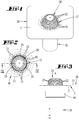
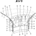
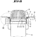
- Ausführungsbeispiele der Erfindung werden nachfolgend anhand beigefügter Zeichnungen erläutert. Es zeigen:
- Fig. 1
- in einer perspektivischen Darstellung einen Regenwassersammler,
- Fig. 2
- die Draufsicht auf den Regenwassersammler,
- Fig. 3
- die Seitenansicht des Regenwassersammlers,
- Fig. 4
- den Schnitt gemäß der Linie IV-IV in
Figur 2 , - Fig. 5
- vergrößert, den Ausschnitt V in
Figur 4 , - Fig. 6
- eine Darstellung gemäß
Figur 5 , jedoch mit dicker schwarzer Linie eine Konturlinie des trichterförmigen Zwischenbereichs zwischen einer Wassereinlauföffnung und einer Wasseraustrittsöffnung, - Fig. 7
- perspektivisch und teilweise aufgebrochen den Zwischenbereich,
- Fig. 8
- den Schnitt gemäß der Linie VIII-VIII in
Figur 4 , - Fig. 9
- vergrößert, den Ausschnitt IX in
Figur 8 , - Fig. 10
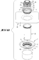
- eine erste Explosionsdarstellung der Einzelteile des Regenwassersammlers,
- Fig. 11
- eine zweite Explosionsdarstellung der Einzelteile des Regenwassersammlers,
- Fig. 12
- den in den
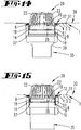
Figuren 1 bis 11 dargestellten Regenwassersammler mit einem Anschlussrohr 35, das einen Reduzierabschnitt 39 aufweist, - Fig. 13
- eine Darstellung gemäß
Figur 12 , jedoch mit einem anders dimensionierten Reduzierabschnitt 39, - Fig. 14
- eine Darstellung gemäß
Figur 12 mit einem dritten Reduzierabschnitt 39, - Fig. 15
- eine Darstellung gemäß
Figur 12 , bei der das Anschlussrohr 35 keinen Reduzierabschnitt aufweist, - Fig. 16
- ein Anwendungsbeispiel, bei dem zwei Regenwassersammler der zuvor beschriebenen Art bei einem Regenwasserablauf verwendet werden, wobei ein oberer Regenwassersammler an eine Dichtfolie oder Dachunterspannbahn angeschlossen ist und ein unterer Regenwassersammler, in dem das Anschlussrohr 35 des oberen Regenwassersammlers steckt, an eine Dampfsperre 38 angeschlossen ist,
- Fig. 17
- schematisch mehrere Konturlinien des Zwischenabschnittes, deren Verlauf durch eine Funktion bestimmt wird, die im Wesentlichen durch die vierte Wurzel des reziproken Abstandes x von der Horizontalebene bestimmt wird.
- Der in den Zeichnungen dargestellte Regenwassersammler ist für den Einsatz an Flachdächern vorgesehen und ist hinsichtlich seiner Abflussleistung hydromechanisch optimiert. Er ist darüber hinaus einfach zu montieren und wartungsarm im Einsatz.
- Der Regenwassersammler besitzt einen Grundkörper 1 aus Kunststoff, der eine runde, im Ausführungsbeispiel im Wesentlichen eckige Grundform aufweist. In der Peripherie bildet er einen horizontalen Abschnitt 2 aus, auf dem eine Dachunterspannbahn, Dichtfolie oder dergleichen aufgelegt sein kann.
- An den horizontalen Abschnitt 2 schließt sich entlang einer kreisförmigen Grenzlinie ein erster Krümmungsabschnitt 4 an, der der Beginn einer trichterförmigen Vertiefung ist, die in ein Anschlussrohr 35 mündet. Dem ersten Krümmungsabschnitt 4 folgt in flächiger Anlage die Dachunterspannbahn bzw. Dichtfolie, die mit ihrer sich an einen kreisförmigen Öffnungsrand 34 anschließende Abschnitt 33 zwischen einem in einer Ringnut 5 des Grundkörpers 1 einliegenden Dichtring 6 und einem Klemmring 12 eingeklemmt ist. Der Öffnungsrand 34 der Dachbahn 30 oder Dichtfolie befindet sich in einem Freiraum 7 zwischen dem Grundkörper 1 und dem Klemmring 12.
- Axial bezogen auf eine durch das Zentrum des Regenwassersammlers gehende Vertikalachse A erstreckt sich unterhalb eines gekrümmten Abschnittes des Grundkörpers 1 ein zylindrischer Abschnitt des Grundkörpers 1, der einen Hals 8 ausbildet. Die Außenwandung des Halses 8 besitzt Rippen 11 in Form eines Außengewindes. Die Innenwandung des Halses 8 besitzt ein Innengewinde 9.
- In das Innengewinde 9 ist das Außengewinde 14 eines Zylinderabschnittes 41 des Klemmrings 12 eingeschraubt. Hierdurch entwickelt sich eine Klemmkraft auf den eingeklemmten Abschnitt 33 der Dachbahn 30 zwischen dem Klemmring 12 und dem Grundkörper 1.
- Eine radial äußere Randkante eines zweiten Krümmungsabschnittes 13, der von einem peripheren Abschnitt des Klemmrings 12 gebildet ist, ist schräg angeschnitten, so dass er sich in einer horizontalen Ebene erstreckt und eine Anströmfläche 15 bildet. Die Knickstelle, in der der erste Krümmungsabschnitt 4 in die Anströmfläche 15 übergeht, ist größer als 120°. Auch die Knickstelle, in der die Anströmfläche 15 in den zweiten Krümmungsabschnitt 13 übergeht, ist größer als 120°.
- Der zweite Krümmungsabschnitt 13 ist durch eine Vielzahl von sich in Radialrichtung erstreckenden Leit-Rippen 19 in einzelne Umfangsfelder unterteilt. Der zweite Krümmungsabschnitt 13 ist ebenso, wie der erste Krümmungsabschnitt 4 in Vertikalrichtung gekrümmt und besitzt eine Neigung zur Vertikalachse A, wobei die Neigung des ersten Krümmungsabschnittes 4 geringer ist als die Neigung des zweiten Krümmungsabschnittes 13.
- Es ist ein Laubfangkörper 20 vorgesehen, der einen Tragring 21 aufweist, von dem nach oben gerichtete flache Laubfangstege 22 abragen. Die Laubfangstege 22 haben einen länglichen Querschnitt, wobei sich die Längsachse der Querschnittsflächen in Radialrichtung erstrecken. Die oberen Enden der Laubfangstege 22 sind mittels eines Kopfstücks miteinander verbunden. Die Leit-Rippen 19 liegen in radialer Flucht zu den Laubfangstegen 22.
- Der Klemmring 12 bildet eine Nische 16, in der der Tragring 21 des Laubfangkörpers 20 Aufnahme findet, so dass der zweite Krümmungsabschnitt 13 bündig in den dritten Krümmungsabschnitt 23 übergeht, der vom Tragring 21 gebildet ist und der gegenüber der Vertikalachse A stärker geneigt ist, als der zweite Krümmungsabschnitt 13. Die Laubfangstege 22 erstrecken sich in Radialrichtung über die gesamte Radialerstreckung des dritten Krümmungsabschnittes 23, der auf seiner Radialinnenseite in einen Zylindermantelflächenabschnitt 24 übergeht. Der Zylindermantelflächenabschnitt 41 des Klemmrings 12 endet an einer Randkante 17 und verläuft bündig zur Zylinderfläche eines Anschlussrohres 35, was von unten her mit einem Außengewinde 36 in das Innengewinde 9 eingeschraubt ist, wobei sich im Bereich einer Randkante 10 des Halses 8 des Grundkörpers 1 ein Dichtring 37 erstreckt.
- Vom Tragring 21 ragen in gleichmäßiger Umfangsverteilung drei Rastzungen 26 in Achsrichtung nach unten ab und greifen in Rastnischen 27 des Zylinderabschnittes 41 des Klemmrings 12 ein.
- Die
Figur 6 zeigt schematisch eine Konturlinie L des Zwischenbereiches zwischen einem horizontalen Abschnitt 31 der Dachbahn 30 bzw. Dichtfolie und dem Zylinderabschnitt 41 bzw. 24. Die Konturlinie L erstreckt sich über eine axiale Höhe H und wird mit der folgenden Bestimmungsgleichung beschrieben
- Wesentlich ist, dass der Radialabstand proportional zur vierten Wurzel des reziproken Axialabstandes ist. Bevorzugt liegen die Konstanten C und K im Bereich von 0,1 bis 2.
- Die
Figur 17 zeigt die Graphen A, B, C, D, E, die nach der folgenden Beziehung berechnet worden sind
Figuren 17 dargestellten Verlauf besitzt, ist die Ablaufleistung optimiert. Dies ist insbesondere dann der Fall, wenn die Konturlinie L von oben bis unten im Wesentlichen knickstellenfrei verläuft und derart gekrümmt ist, dass vertikal oberhalb der Wassereinlauföffnung aufgestautes Wasser wirbelfrei und ohne Strömungsabriss in eine Vertikalströmung durch ein sich an die Wasserauslauföffnung anschließendes Fallrohr einströmt. Die Vertikalkomponente der Geschwindigkeit des von oben durch Druck einer oberen Wassersäule und nach unten durch Sog einer unteren Wassersäule beaufschlagte Wasser ist bevorzugt in jedem Volumenbereich des Zwischenbereiches größer als die Radialkomponente der Wassergeschwindigkeit. Dies führt dazu, dass sich kaum Strömungsabrisse ausbilden und es zu keinem Rückstau kommt. Die Konturlinie L ist bevorzugt nicht unterbrochen und wird auch nicht durch Querrippen oder dergleichen gestört. Die vor den Laubfangstegen 22 angeordneten Leit-Rippen 19 vermindern darüber hinaus die Wirbelbildung, so dass sich anders als beim Stand der Technik eine im Wesentlichen radiale/axiale Strömung ausbildet.Liste der Bezugszeichen 1 Grundkörper 26 Rastzunge 2 horizontaler Abschnitt 27 Rastnische 3 Auflagefläche 28 Ausnehmung 4 erster Krümmungsabschnitt 29 Vorsprung 5 Ringnut 30 Dachbahn 6 Dichtring 31 horizontaler Abschnitt 7 Freiraum 32 gekrümmter Abschnitt 8 Hals 33 eingeklemmter Abschnitt 9 Innengewinde 34 Öffnungsrand 10 Randkante 35 Anschlussrohr 11 Rippe/Außengewinde 36 Außengewinde 12 Klemmring 37 Dichtring 13 zweiter Krümmungsabschnitt 38 Dampfsperre 14 Außengewinde 39 Reduzierabschnitt 15 Anströmfläche 40 Manschette 16 Nische 41 Zylinderabschnitt 17 Randkante 18 Freiraum 19 Leit-Rippe A Vertikalachse 20 Laubfangkörper H Höhe 21 Tragring L Konturlinie 22 Laubfangsteg 23 dritter Krümmungsabschnitt 24 Zylindermantelflächenabschnitt 25 Randkante
Claims (14)
- Regenwassersammler, insbesondere für ein Flachdach, mit einer oben angeordneten Wassereinlauföffnung, einer unten angeordneten durchmesserkleineren Wasseraustrittsöffnung und einem dazwischenliegenden, bezogen auf eine Vertikalachse (A) rotationssymmetrischen Zwischenabschnitt, dessen Innenwandung sich entlang einer oben flach geneigt zu einer Horizontalebene entspringenden und unten in einem Abstand (H) von der Horizontalebene, steil auslaufend in eine sich um die Vertikalachse erstreckenden inneren Zylindermantelfläche eines Zylinderabschnitts (24) auslaufend verlaufenden Konturlinie (L) erstreckt, dadurch gekennzeichnet, dass die Konturlinie (L) durch den Graphen einer Funktion R = D0 ∗ (H/x)¼ ∗ C + K definiert ist, die zu jedem Axialabstand (x) von der Horizontalebene einen Radialabstand (R) angibt, wobei C und K im Bereich von 0,1 und 2 liegen, wobei D0 dem Durchmesser des Zylinderabschnitts (24) entspricht.
- Regenwassersammler nach Anspruch 1, dadurch gekennzeichnet, dass die Konturlinie (L) durch den Graphen einer Funktion

- Regenwassersammler nach einem der Ansprüche 1 oder 2, dadurch gekennzeichnet, dass C im Bereich zwischen 0,1 und 1 liegt und insbesondere zwischen 0,1 und 0,7 liegt.
- Regenwassersammler nach einem der vorhergehenden Ansprüche, wobei die Konturlinie (L) mehrere Krümmungsabschnitte (4,13, 23) aufweist, dadurch gekennzeichnet, dass ein erster, an die Horizontalebene angrenzender Krümmungsabschnitt (4) von einem Grundkörper (1) vorgegeben ist, auf dem ein gekrümmter Abschnitt (32) einer Dachbahn (30) aufliegen kann, wobei ein zweiter Krümmungsabschnitt (13), der gegenüber der Vertikalachse (A) stärker geneigt ist als der erste Krümmungsabschnitt (4) von einem Klemmring (12) ausgebildet ist, der einen eingeklemmten Randabschnitt (33) der Dachbahn (30) zwischen sich und dem Grundkörper (1) einklemmen kann, und wobei ein dritter Krümmungsabschnitt (23), der gegenüber der Vertikalachse (A) stärker geneigt ist als der zweite Krümmungsabschnitt (13), von einem in den Klemmring (12) eingesetzten Laubfangkörper (20) ausgebildet ist.
- Regenwassersammler nach Anspruch 4, dadurch gekennzeichnet, dass der Grundkörper (1) einen Horizontalabschnitt (2) aufweist, der in der Horizontalebene liegt und einen zylinderförmigen Hals (8) ausbildet, der ein Innengewinde (9) aufweist, in dem ein Außengewinde (14) des Klemmrings (12) eingedreht ist.
- Regenwassersammler nach einem der Ansprüche 4 oder 5, dadurch gekennzeichnet, dass der Grundkörper (1) ein Innengewinde (9) aufweist, in dem ein Außengewinde (36) eines Anschlussrohres (35) eingedreht ist.
- Regenwassersammler nach einem der Ansprüche 4 bis 6, dadurch gekennzeichnet, dass die Innenwandung des Anschlussrohres (35) mit der Innenwandung eines zylindrischen Abschnitts des Klemmrings (12) fluchtet.
- Regenwassersammler nach einem der Ansprüche 4 bis 7, dadurch gekennzeichnet, dass der dritte Krümmungsabschnitt (23) von einem Tragring (21) des Laubfangkörpers (20) ausbildet ist, dem sich ein Zylinderabschnitt mit einer Zylinderinnenmantelfläche (24) anliegt.
- Regenwassersammler nach einem der Ansprüche 4 bis 8, gekennzeichnet durch von einem Tragring (21) des Laubfangkörpers (20) insbesondere schräg zur Vertikalachse (A) aufwärts sich erstreckende Laubfangstege (22), die als Flachteile ausgebildet sind, die sich, bezogen auf die Vertikalachse (A), in Radialrichtung erstrecken.
- Regenwassersammler nach einem der Ansprüche 4 bis 9, dadurch gekennzeichnet, dass der Klemmring (12) im Bereich des zweiten Krümmungsabschnittes (13) sich in Radialrichtung erstreckende Leit-Rippen (19) aufweist, die fluchtend radial außerhalb der Laubfangstege (22) angeordnet sind.
- Regenwassersammler nach einem der Ansprüche 4 bis 10, dadurch gekennzeichnet, dass der Laubfangkörper (20) eine in den Hals (8) des Grundkörpers (1) hineinragende Rastzunge (26) aufweist, die mit einem Rastvorsprung in eine Rastnische (27) des Klemmrings (12) eingreift.
- Regenwassersammler nach einem der Ansprüche 6 bis 11, dadurch gekennzeichnet, dass das Anschlussrohr (35) einen Reduzierabschnitt (39) aufweist, in dem sich der Durchmesser des Anschlussrohres (35) vermindert.
- Regenwassersammler nach Anspruch 12, dadurch gekennzeichnet, dass ein nicht durchmesserreduziertes Anschlussrohr (35) in den Zylinderabschnitt (41) des Klemmrings (12) eines zweiten Regenwassersammlers eingesteckt ist, bei dem eine Dampfsperre (38) zwischen Grundkörper (1) und Klemmring (12) einklemmbar ist.
- Regenwassersammler nach einem der Ansprüche 10 bis 13, dadurch gekennzeichnet, dass die Leit-Rippen (19) und die Laubfangstege (22) dieselbe in Umfangsrichtung gemessene Breite aufweisen und unmittelbar aneinander angrenzen.
Priority Applications (1)
| Application Number | Priority Date | Filing Date | Title |
|---|---|---|---|
| PL18202449T PL3480387T3 (pl) | 2017-11-06 | 2018-10-25 | Zbieracz wody deszczowej |
Applications Claiming Priority (1)
| Application Number | Priority Date | Filing Date | Title |
|---|---|---|---|
| DE102017125882.5A DE102017125882A1 (de) | 2017-11-06 | 2017-11-06 | Regenwassersammler |
Publications (2)
| Publication Number | Publication Date |
|---|---|
| EP3480387A1 EP3480387A1 (de) | 2019-05-08 |
| EP3480387B1 true EP3480387B1 (de) | 2020-05-13 |
Family
ID=63998527
Family Applications (1)
| Application Number | Title | Priority Date | Filing Date |
|---|---|---|---|
| EP18202449.7A Active EP3480387B1 (de) | 2017-11-06 | 2018-10-25 | Regenwassersammler |
Country Status (6)
| Country | Link |
|---|---|
| EP (1) | EP3480387B1 (de) |
| DE (1) | DE102017125882A1 (de) |
| ES (1) | ES2805962T3 (de) |
| HU (1) | HUE051139T2 (de) |
| PL (1) | PL3480387T3 (de) |
| PT (1) | PT3480387T (de) |
Families Citing this family (2)
| Publication number | Priority date | Publication date | Assignee | Title |
|---|---|---|---|---|
| RU197611U1 (ru) * | 2020-01-22 | 2020-05-18 | Общество с ограниченной ответственностью "ФАХМАНН РУССЛАНД" | Кровельная водосточная воронка |
| RU198187U1 (ru) * | 2020-01-22 | 2020-06-23 | Общество с ограниченной ответственностью "ФАХМАНН РУССЛАНДА" | Кровельная водосточная воронка |
Family Cites Families (8)
| Publication number | Priority date | Publication date | Assignee | Title |
|---|---|---|---|---|
| US2765865A (en) * | 1951-01-15 | 1956-10-09 | J A Zurn Mfg Co | Roof drain extension |
| DE6903939U (de) * | 1969-02-01 | 1969-05-22 | Dynamit Nobel Ag | Wasserablauf fuer flachdaecher |
| SE451610B (sv) * | 1983-04-14 | 1987-10-19 | Kontekla Oy | Skrepsil |
| DE8805040U1 (de) * | 1988-04-16 | 1988-05-26 | Vahlbrauk, Karl Heinz, 3353 Bad Gandersheim | Dach- bzw. Deckenelement |
| SE9100680L (sv) * | 1991-03-07 | 1992-09-08 | Sjoebo Bruk Ab | Anordning vid golvbrunnar |
| DE29805928U1 (de) | 1998-04-01 | 1999-08-05 | Klöber, Johannes, 58256 Ennepetal | Regenwassersammler, insbesondere für Flachdächer |
| IT1395999B1 (it) * | 2009-03-10 | 2012-11-09 | Valsir Spa | Pozzetto di scarico d'acqua, in particolare per sistemi ad effetto sifonico di drenaggio dei tetti |
| BE1019738A5 (nl) * | 2010-05-20 | 2012-12-04 | Aquadraat Enigineering Bvba | Dakkolk voor hemelwaterafvoer in onderdruk. |
-
2017
- 2017-11-06 DE DE102017125882.5A patent/DE102017125882A1/de not_active Ceased
-
2018
- 2018-10-25 PL PL18202449T patent/PL3480387T3/pl unknown
- 2018-10-25 EP EP18202449.7A patent/EP3480387B1/de active Active
- 2018-10-25 HU HUE18202449A patent/HUE051139T2/hu unknown
- 2018-10-25 ES ES18202449T patent/ES2805962T3/es active Active
- 2018-10-25 PT PT182024497T patent/PT3480387T/pt unknown
Non-Patent Citations (1)
| Title |
|---|
| None * |
Also Published As
| Publication number | Publication date |
|---|---|
| DE102017125882A1 (de) | 2019-05-09 |
| EP3480387A1 (de) | 2019-05-08 |
| PT3480387T (pt) | 2020-07-14 |
| PL3480387T3 (pl) | 2020-11-16 |
| HUE051139T2 (hu) | 2021-03-01 |
| ES2805962T3 (es) | 2021-02-16 |
Similar Documents
| Publication | Publication Date | Title |
|---|---|---|
| EP2952752B1 (de) | Umlenkbogen | |
| EP2230359A2 (de) | Bausatz für eine Verbindung eines Inspektions-Schachtes mit einer Abfluss-Leitung | |
| DE102012112852B4 (de) | Rohrbogen zur Abgasführung in Heizungsanlagen | |
| EP3480387A1 (de) | Regenwassersammler | |
| WO2010091519A1 (de) | Vorrichtung zum befestigen von geländern mit platten aus glas oder anderen zerbrechlichen materialien | |
| DE102014012288A1 (de) | Regenwasserfilter | |
| EP2159337B1 (de) | Bodenablauf, insbesondere für bodengleiche Dusche | |
| EP1826334B1 (de) | Notüberlauf | |
| DE4040495C2 (de) | ||
| EP3168375B1 (de) | Wandarmatur | |
| DE3505196A1 (de) | Waermetauscher, insbesondere fuer kraftfahrzeuge | |
| DE102012024358B4 (de) | Entwässerungsvorrichtung mit einer Abflussleitung | |
| EP2246622A2 (de) | Entlüftungsanordnung zur Montage auf einem Gebäudedach | |
| DE3105504C2 (de) | ||
| EP3763880B1 (de) | Vorrichtung zum vorzugsweise bündigen einbau in die strassen-/fahrbahndecke | |
| EP2687644B1 (de) | Rinnenabdeckung | |
| DE19904699C2 (de) | Freispiegel-Wasserablauf | |
| DE102015109717B4 (de) | Vorrichtung zur Reinigung einer Dachrinne | |
| DE29708509U1 (de) | Anschlußstück zum Anschließen eines Abzweigrohres an ein verlegtes Kanalisationsrohr | |
| DE102005017171B4 (de) | Halteanordnung für eine Blitzfangstange | |
| DE202015101954U1 (de) | Sicherheitsbrücke | |
| DE102005020300B4 (de) | Flachgully-waagerecht zu bestehenden Gullysystemen passend | |
| DE202006013874U1 (de) | Entwässerungssystem für Flachdächer und/oder andere Flachbauten, insbesondere Notentwässerung | |
| DE29715010U1 (de) | Abwasser-Geruchsverschluß | |
| DE102012110223A1 (de) | Ablaufanordnung |
Legal Events
| Date | Code | Title | Description |
|---|---|---|---|
| PUAI | Public reference made under article 153(3) epc to a published international application that has entered the european phase |
Free format text: ORIGINAL CODE: 0009012 |
|
| STAA | Information on the status of an ep patent application or granted ep patent |
Free format text: STATUS: THE APPLICATION HAS BEEN PUBLISHED |
|
| AK | Designated contracting states |
Kind code of ref document: A1 Designated state(s): AL AT BE BG CH CY CZ DE DK EE ES FI FR GB GR HR HU IE IS IT LI LT LU LV MC MK MT NL NO PL PT RO RS SE SI SK SM TR |
|
| AX | Request for extension of the european patent |
Extension state: BA ME |
|
| STAA | Information on the status of an ep patent application or granted ep patent |
Free format text: STATUS: REQUEST FOR EXAMINATION WAS MADE |
|
| 17P | Request for examination filed |
Effective date: 20190821 |
|
| RBV | Designated contracting states (corrected) |
Designated state(s): AL AT BE BG CH CY CZ DE DK EE ES FI FR GB GR HR HU IE IS IT LI LT LU LV MC MK MT NL NO PL PT RO RS SE SI SK SM TR |
|
| GRAP | Despatch of communication of intention to grant a patent |
Free format text: ORIGINAL CODE: EPIDOSNIGR1 |
|
| STAA | Information on the status of an ep patent application or granted ep patent |
Free format text: STATUS: GRANT OF PATENT IS INTENDED |
|
| RIC1 | Information provided on ipc code assigned before grant |
Ipc: E04D 13/04 20060101AFI20191106BHEP |
|
| INTG | Intention to grant announced |
Effective date: 20191127 |
|
| GRAS | Grant fee paid |
Free format text: ORIGINAL CODE: EPIDOSNIGR3 |
|
| GRAL | Information related to payment of fee for publishing/printing deleted |
Free format text: ORIGINAL CODE: EPIDOSDIGR3 |
|
| GRAS | Grant fee paid |
Free format text: ORIGINAL CODE: EPIDOSNIGR3 |
|
| GRAA | (expected) grant |
Free format text: ORIGINAL CODE: 0009210 |
|
| STAA | Information on the status of an ep patent application or granted ep patent |
Free format text: STATUS: THE PATENT HAS BEEN GRANTED |
|
| AK | Designated contracting states |
Kind code of ref document: B1 Designated state(s): AL AT BE BG CH CY CZ DE DK EE ES FI FR GB GR HR HU IE IS IT LI LT LU LV MC MK MT NL NO PL PT RO RS SE SI SK SM TR |
|
| REG | Reference to a national code |
Ref country code: GB Ref legal event code: FG4D Free format text: NOT ENGLISH |
|
| REG | Reference to a national code |
Ref country code: CH Ref legal event code: EP |
|
| REG | Reference to a national code |
Ref country code: DE Ref legal event code: R096 Ref document number: 502018001436 Country of ref document: DE |
|
| REG | Reference to a national code |
Ref country code: CH Ref legal event code: NV Representative=s name: FELBER UND PARTNER AG, CH |
|
| REG | Reference to a national code |
Ref country code: AT Ref legal event code: REF Ref document number: 1270461 Country of ref document: AT Kind code of ref document: T Effective date: 20200615 |
|
| REG | Reference to a national code |
Ref country code: PT Ref legal event code: SC4A Ref document number: 3480387 Country of ref document: PT Date of ref document: 20200714 Kind code of ref document: T Free format text: AVAILABILITY OF NATIONAL TRANSLATION Effective date: 20200708 |
|
| REG | Reference to a national code |
Ref country code: SK Ref legal event code: T3 Ref document number: E 34426 Country of ref document: SK |
|
| REG | Reference to a national code |
Ref country code: LT Ref legal event code: MG4D |
|
| REG | Reference to a national code |
Ref country code: NL Ref legal event code: MP Effective date: 20200513 |
|
| PG25 | Lapsed in a contracting state [announced via postgrant information from national office to epo] |
Ref country code: LT Free format text: LAPSE BECAUSE OF FAILURE TO SUBMIT A TRANSLATION OF THE DESCRIPTION OR TO PAY THE FEE WITHIN THE PRESCRIBED TIME-LIMIT Effective date: 20200513 Ref country code: GR Free format text: LAPSE BECAUSE OF FAILURE TO SUBMIT A TRANSLATION OF THE DESCRIPTION OR TO PAY THE FEE WITHIN THE PRESCRIBED TIME-LIMIT Effective date: 20200814 Ref country code: FI Free format text: LAPSE BECAUSE OF FAILURE TO SUBMIT A TRANSLATION OF THE DESCRIPTION OR TO PAY THE FEE WITHIN THE PRESCRIBED TIME-LIMIT Effective date: 20200513 Ref country code: NO Free format text: LAPSE BECAUSE OF FAILURE TO SUBMIT A TRANSLATION OF THE DESCRIPTION OR TO PAY THE FEE WITHIN THE PRESCRIBED TIME-LIMIT Effective date: 20200813 Ref country code: SE Free format text: LAPSE BECAUSE OF FAILURE TO SUBMIT A TRANSLATION OF THE DESCRIPTION OR TO PAY THE FEE WITHIN THE PRESCRIBED TIME-LIMIT Effective date: 20200513 Ref country code: IS Free format text: LAPSE BECAUSE OF FAILURE TO SUBMIT A TRANSLATION OF THE DESCRIPTION OR TO PAY THE FEE WITHIN THE PRESCRIBED TIME-LIMIT Effective date: 20200913 |
|
| PG25 | Lapsed in a contracting state [announced via postgrant information from national office to epo] |
Ref country code: BG Free format text: LAPSE BECAUSE OF FAILURE TO SUBMIT A TRANSLATION OF THE DESCRIPTION OR TO PAY THE FEE WITHIN THE PRESCRIBED TIME-LIMIT Effective date: 20200813 Ref country code: HR Free format text: LAPSE BECAUSE OF FAILURE TO SUBMIT A TRANSLATION OF THE DESCRIPTION OR TO PAY THE FEE WITHIN THE PRESCRIBED TIME-LIMIT Effective date: 20200513 Ref country code: RS Free format text: LAPSE BECAUSE OF FAILURE TO SUBMIT A TRANSLATION OF THE DESCRIPTION OR TO PAY THE FEE WITHIN THE PRESCRIBED TIME-LIMIT Effective date: 20200513 Ref country code: LV Free format text: LAPSE BECAUSE OF FAILURE TO SUBMIT A TRANSLATION OF THE DESCRIPTION OR TO PAY THE FEE WITHIN THE PRESCRIBED TIME-LIMIT Effective date: 20200513 |
|
| PG25 | Lapsed in a contracting state [announced via postgrant information from national office to epo] |
Ref country code: AL Free format text: LAPSE BECAUSE OF FAILURE TO SUBMIT A TRANSLATION OF THE DESCRIPTION OR TO PAY THE FEE WITHIN THE PRESCRIBED TIME-LIMIT Effective date: 20200513 Ref country code: NL Free format text: LAPSE BECAUSE OF FAILURE TO SUBMIT A TRANSLATION OF THE DESCRIPTION OR TO PAY THE FEE WITHIN THE PRESCRIBED TIME-LIMIT Effective date: 20200513 |
|
| PG25 | Lapsed in a contracting state [announced via postgrant information from national office to epo] |
Ref country code: SM Free format text: LAPSE BECAUSE OF FAILURE TO SUBMIT A TRANSLATION OF THE DESCRIPTION OR TO PAY THE FEE WITHIN THE PRESCRIBED TIME-LIMIT Effective date: 20200513 Ref country code: RO Free format text: LAPSE BECAUSE OF FAILURE TO SUBMIT A TRANSLATION OF THE DESCRIPTION OR TO PAY THE FEE WITHIN THE PRESCRIBED TIME-LIMIT Effective date: 20200513 Ref country code: DK Free format text: LAPSE BECAUSE OF FAILURE TO SUBMIT A TRANSLATION OF THE DESCRIPTION OR TO PAY THE FEE WITHIN THE PRESCRIBED TIME-LIMIT Effective date: 20200513 Ref country code: EE Free format text: LAPSE BECAUSE OF FAILURE TO SUBMIT A TRANSLATION OF THE DESCRIPTION OR TO PAY THE FEE WITHIN THE PRESCRIBED TIME-LIMIT Effective date: 20200513 |
|
| REG | Reference to a national code |
Ref country code: ES Ref legal event code: FG2A Ref document number: 2805962 Country of ref document: ES Kind code of ref document: T3 Effective date: 20210216 Ref country code: DE Ref legal event code: R097 Ref document number: 502018001436 Country of ref document: DE |
|
| REG | Reference to a national code |
Ref country code: HU Ref legal event code: AG4A Ref document number: E051139 Country of ref document: HU |
|
| PLBE | No opposition filed within time limit |
Free format text: ORIGINAL CODE: 0009261 |
|
| STAA | Information on the status of an ep patent application or granted ep patent |
Free format text: STATUS: NO OPPOSITION FILED WITHIN TIME LIMIT |
|
| 26N | No opposition filed |
Effective date: 20210216 |
|
| PG25 | Lapsed in a contracting state [announced via postgrant information from national office to epo] |
Ref country code: SI Free format text: LAPSE BECAUSE OF FAILURE TO SUBMIT A TRANSLATION OF THE DESCRIPTION OR TO PAY THE FEE WITHIN THE PRESCRIBED TIME-LIMIT Effective date: 20200513 |
|
| PG25 | Lapsed in a contracting state [announced via postgrant information from national office to epo] |
Ref country code: MC Free format text: LAPSE BECAUSE OF FAILURE TO SUBMIT A TRANSLATION OF THE DESCRIPTION OR TO PAY THE FEE WITHIN THE PRESCRIBED TIME-LIMIT Effective date: 20200513 Ref country code: LU Free format text: LAPSE BECAUSE OF NON-PAYMENT OF DUE FEES Effective date: 20201025 |
|
| REG | Reference to a national code |
Ref country code: BE Ref legal event code: MM Effective date: 20201031 |
|
| PG25 | Lapsed in a contracting state [announced via postgrant information from national office to epo] |
Ref country code: BE Free format text: LAPSE BECAUSE OF NON-PAYMENT OF DUE FEES Effective date: 20201031 |
|
| PG25 | Lapsed in a contracting state [announced via postgrant information from national office to epo] |
Ref country code: TR Free format text: LAPSE BECAUSE OF FAILURE TO SUBMIT A TRANSLATION OF THE DESCRIPTION OR TO PAY THE FEE WITHIN THE PRESCRIBED TIME-LIMIT Effective date: 20200513 Ref country code: MT Free format text: LAPSE BECAUSE OF FAILURE TO SUBMIT A TRANSLATION OF THE DESCRIPTION OR TO PAY THE FEE WITHIN THE PRESCRIBED TIME-LIMIT Effective date: 20200513 Ref country code: CY Free format text: LAPSE BECAUSE OF FAILURE TO SUBMIT A TRANSLATION OF THE DESCRIPTION OR TO PAY THE FEE WITHIN THE PRESCRIBED TIME-LIMIT Effective date: 20200513 |
|
| PG25 | Lapsed in a contracting state [announced via postgrant information from national office to epo] |
Ref country code: MK Free format text: LAPSE BECAUSE OF FAILURE TO SUBMIT A TRANSLATION OF THE DESCRIPTION OR TO PAY THE FEE WITHIN THE PRESCRIBED TIME-LIMIT Effective date: 20200513 |
|
| P01 | Opt-out of the competence of the unified patent court (upc) registered |
Effective date: 20230512 |
|
| REG | Reference to a national code |
Ref country code: CH Ref legal event code: U11 Free format text: ST27 STATUS EVENT CODE: U-0-0-U10-U11 (AS PROVIDED BY THE NATIONAL OFFICE) Effective date: 20251101 |
|
| PGFP | Annual fee paid to national office [announced via postgrant information from national office to epo] |
Ref country code: HU Payment date: 20251020 Year of fee payment: 8 |
|
| PGFP | Annual fee paid to national office [announced via postgrant information from national office to epo] |
Ref country code: PT Payment date: 20251014 Year of fee payment: 8 |
|
| PGFP | Annual fee paid to national office [announced via postgrant information from national office to epo] |
Ref country code: DE Payment date: 20251020 Year of fee payment: 8 |
|
| PGFP | Annual fee paid to national office [announced via postgrant information from national office to epo] |
Ref country code: GB Payment date: 20251024 Year of fee payment: 8 |
|
| PGFP | Annual fee paid to national office [announced via postgrant information from national office to epo] |
Ref country code: AT Payment date: 20251021 Year of fee payment: 8 |
|
| PGFP | Annual fee paid to national office [announced via postgrant information from national office to epo] |
Ref country code: IT Payment date: 20251031 Year of fee payment: 8 |
|
| PGFP | Annual fee paid to national office [announced via postgrant information from national office to epo] |
Ref country code: FR Payment date: 20251027 Year of fee payment: 8 |
|
| PGFP | Annual fee paid to national office [announced via postgrant information from national office to epo] |
Ref country code: CH Payment date: 20251101 Year of fee payment: 8 |
|
| PGFP | Annual fee paid to national office [announced via postgrant information from national office to epo] |
Ref country code: IE Payment date: 20251021 Year of fee payment: 8 Ref country code: CZ Payment date: 20251015 Year of fee payment: 8 |
|
| PGFP | Annual fee paid to national office [announced via postgrant information from national office to epo] |
Ref country code: PL Payment date: 20251014 Year of fee payment: 8 |
|
| PGFP | Annual fee paid to national office [announced via postgrant information from national office to epo] |
Ref country code: SK Payment date: 20251016 Year of fee payment: 8 |
|
| PGFP | Annual fee paid to national office [announced via postgrant information from national office to epo] |
Ref country code: ES Payment date: 20251114 Year of fee payment: 8 |