EP0502493B1 - Clamping device for floor drains - Google Patents
Clamping device for floor drains Download PDFInfo
- Publication number
- EP0502493B1 EP0502493B1 EP92103668A EP92103668A EP0502493B1 EP 0502493 B1 EP0502493 B1 EP 0502493B1 EP 92103668 A EP92103668 A EP 92103668A EP 92103668 A EP92103668 A EP 92103668A EP 0502493 B1 EP0502493 B1 EP 0502493B1
- Authority
- EP
- European Patent Office
- Prior art keywords
- clamping ring
- inlet member
- downwardly
- angle
- directed wall
- Prior art date
- Legal status (The legal status is an assumption and is not a legal conclusion. Google has not performed a legal analysis and makes no representation as to the accuracy of the status listed.)
- Expired - Lifetime
Links
- 230000006835 compression Effects 0.000 claims description 3
- 238000007906 compression Methods 0.000 claims description 3
- 230000037431 insertion Effects 0.000 claims 2
- 238000003780 insertion Methods 0.000 claims 2
- 238000007789 sealing Methods 0.000 description 4
Images


Classifications
-
- E—FIXED CONSTRUCTIONS
- E03—WATER SUPPLY; SEWERAGE
- E03F—SEWERS; CESSPOOLS
- E03F5/00—Sewerage structures
- E03F5/04—Gullies inlets, road sinks, floor drains with or without odour seals or sediment traps
- E03F5/0407—Floor drains for indoor use
- E03F5/0409—Devices for preventing seepage around the floor drain
-
- E—FIXED CONSTRUCTIONS
- E03—WATER SUPPLY; SEWERAGE
- E03F—SEWERS; CESSPOOLS
- E03F5/00—Sewerage structures
- E03F5/04—Gullies inlets, road sinks, floor drains with or without odour seals or sediment traps
- E03F5/0407—Floor drains for indoor use
-
- E—FIXED CONSTRUCTIONS
- E04—BUILDING
- E04D—ROOF COVERINGS; SKY-LIGHTS; GUTTERS; ROOF-WORKING TOOLS
- E04D13/00—Special arrangements or devices in connection with roof coverings; Protection against birds; Roof drainage ; Sky-lights
- E04D13/04—Roof drainage; Drainage fittings in flat roofs, balconies or the like
- E04D13/0404—Drainage on the roof surface
- E04D13/0409—Drainage outlets, e.g. gullies
-
- E—FIXED CONSTRUCTIONS
- E04—BUILDING
- E04D—ROOF COVERINGS; SKY-LIGHTS; GUTTERS; ROOF-WORKING TOOLS
- E04D13/00—Special arrangements or devices in connection with roof coverings; Protection against birds; Roof drainage ; Sky-lights
- E04D13/04—Roof drainage; Drainage fittings in flat roofs, balconies or the like
- E04D13/0404—Drainage on the roof surface
- E04D13/0409—Drainage outlets, e.g. gullies
- E04D2013/0436—Drainage outlets, e.g. gullies with sealing means
Definitions
- the present invention relates to a clamping device for floor drains including an inlet member (2) into which a floor covering (3) is insertable, whereby the floor covering (3) inserted into the inlet member (2) is arranged to engage a downwardly directed wall (4) of said inlet member (2), whereby a clamping ring (5) is provided within the floor covering (3) inserted into the inlet member (2), said clamping ring (5) being arranged to press the floor covering (3) inserted into the inlet member (2) in a direction outwards against the downwardly directed wall (4) and said clamping ring (5) being split and provided with a spring (6) which is arranged to press said clamping ring (5) in a direction outwards against the floor covering (3), whereby one side (7) of the clamping ring (5) facing outwards towards the floor covering (3) includes two surfaces (8, 9) extending at an angle relative to each other and together defining a point (10) facing outwards towards said floor covering (3), whereby the downwardly directed wall (4) comprises a relative to the clamping ring (5)
- Clamping rings of the above type are already known from WO-A-90/02232.
- the shape of the inlet member of this floor drain does not provide for reliable attachment of the clamping ring, but said ring can glide upwards and loosen.
- the object of the present invention is to eliminate this problem and provide a device at which the clamping ring can not glide upwards and yet exert a great clamping force or pressure against the floor covering. This is arrived at according to the invention essentially by means of the characterizing features of subsequent claim 1.
- the inlet member has been designed with a strongly inclined downwardly/outwardly directed wall portion, it is ensured that the clamping ring is prevented from gliding upwards while it at the same time can engage the floor covering with a great pressure, because the spring can expand the clamping ring after it in compressed condition has been moved past the downwardly/outwardly directed wall portion.
- This floor covering 3 shall be held closely against a downwardly directed wall 4 of the inlet member 2 by means of a clamping ring 5 mounted in said inlet member 2.
- This clamping ring 5 is split (see fig. 4) and comprises a spring 6 which permits sufficient compression thereof in radial direction for inserting it into the inlet member 2. Thereafter, when the clamping ring 5 is released, the spring 6 will dilate or expand said clamping ring radially outwards until it engages the floor covering 3.
- clamping ring 5 will press the floor covering 3 in outwards direction against the downwardly directed wall 4 of the inlet member 2, such that the floor covering 3 closely engages said wall 4.
- Clamping rings 5 of this type are described in detail in our SE patent specification No. 8802915-2.
- the side 7 of the clamping ring 5 facing outwards towards the floor covering 3 includes two surfaces 8 and 9 which extend at an angle relative to each other for defining a point 10 facing outwards towards the floor covering 3.
- the downwardly directed wall 4 of the inlet member 2 includes a wall portion 11 which is directed downwards/outwards relative to the clamping ring 5 and this wall portion 11 is at least partially situated on a somewhat higher level H1 than the level H2 of the point 10 of the clamping ring 5 in its operative position in the inlet member 2, i.e. when it engages the seat 2a in said inlet member 2.
- the angle ⁇ between the horizontal plane (here illustrated with the line H2 in fig. 1) and the upper surface 9 of the clamping ring 5 is equal to or somewhat smaller than the angle ⁇ between said wall portion 11 and the horizontal plane (here illustrated as the line H1 in fig. 1). It is hereby provided that the floor drain 1 is located in its intended position relative to the horizontal plane; if the floor drain 1 is located somewhat inclined relative to this intended position, the angles ⁇ and ⁇ will change correspondingly relative to the horizontal plane, but said relationship between these angles will remain unaltered.
- the downwardly/outwardly directed wall portion 11 is located on a somewhat higher level than the point 10 of the clamping ring 5 (in fig. 1 this difference in level corresponds with the distance between the levels H1 and H2).
- the angle ⁇ between the upper surface of the clamping ring 5 and the horizontal plane H2 preferably lies within a range of 10-55°.
- the angle ⁇ is about 45°.
- a point 10 of a suitable shape is obtained if the angle ⁇ between the upper and lower surfaces 9 and 8 of the clamping ring 5 lies within a range of 100-140°.
- this angle ⁇ is about 120°.
- the downwardly/outwardly directed wall portion 11 defines with the horizontal plane H1 preferably an angle ⁇ within a range of 55-65°.
- the angle ⁇ is about 60°.
- the inlet member 2 mentioned above may preferably also be used for mounting an extension ring 12 if the floor level is raised and one wish to maintain the existing floor drain 1 but yet provide an inlet member 2 located in level with the raised floor level.
- This extension ring 12 can be snapped onto the inlet member 2 of the floor drain while said extension ring 12 comprises a snap-in portion 13 which is intended to be moved at least partially beyond the downwardly/outwardly directed wall portion 11 until said snap-in portion 13 is snapped onto the inlet member 2 (see fig. 2).
- the snap-in portion 13 preferably includes a point 14 which, when pressing down the extension ring 12 into the inlet member 2, is engageable with the downwardly/outwardly directed wall portion 11 or preferably with the downwardly directed wall 4 just beneath said wall portion 11.
- the point 14 is preferably provided at such a distance above the lower edge 15 of the extension ring 12 that the extension ring 12 in its operative function is clamped between the seat 2a and the wall portion 11 or the downwardly directed wall 4, just beneath said wall portion 11 depending on where the point 14 is engaged. This means that the extension ring 12, in its operative position, can not move in axial direction relative to the floor drain 1.
- the snap-in portion 13 preferably comprises an outer side 16 with the same or similar shape as the outer side 7 of the clamping ring 5.
- the snap-in portion 13 may include an upper surface 17 with the same angle ⁇ to the horizontal plane as the surface 9 of the clamping ring 5 (see fig. 3).
- the outer side 16 may have a lower surface 18 and the angle between these surfaces 17, 18 can correspond with the angle ⁇ between corresponding surfaces 8, 9 on the clamping ring 5.
- a groove 19 for a sealing ring 20 which is adapted to provide a sealing between the inlet member 2 and the outer side of the extension ring 12.
- said inlet member 2 has the same shape as the inlet member 2 of the floor drain 1, i.e. comprises a downwardly/inwardly directed wall portion 11 and so on, and those parts of the inlet member 2 of the extension ring 12 which correspond with the same parts of the inlet member 2 of the floor drain 1 have for the purpose of simplification received the same reference numerals in fig. 2.
- the inlet member 2 preferably comprises a downwardly bent surface 21, through which the floor covering 3 extends downwards towards the downwardly directed wall 4.
- This downwardly bent surface 21 can down below define a constriction 22 of the inlet member 2 and the downwardly/outwardly directed wall portion 11 can be located just beneath this constriction 22 (see fig. 1).
- the downwardly/outwardly directed wall portion 11 preferably transforms into a vertically or substantially vertically directed section 23 of the downwardly directed wall 4 and this section 23 preferably has a rough portion 24 situated on the same level H2 as the point 10 of the clamping ring 5.
- the invention is not limited to the illustrated embodiment but may vary within the scope of the following claims.
- the inlet member need not necessarily be circular and eventually neither the clamping ring.
- the clamping ring can also be of another type than shown.
Landscapes
- Engineering & Computer Science (AREA)
- Health & Medical Sciences (AREA)
- Life Sciences & Earth Sciences (AREA)
- Hydrology & Water Resources (AREA)
- Public Health (AREA)
- Water Supply & Treatment (AREA)
- Architecture (AREA)
- Civil Engineering (AREA)
- Structural Engineering (AREA)
- Floor Finish (AREA)
- Installation Of Indoor Wiring (AREA)
- Specific Sealing Or Ventilating Devices For Doors And Windows (AREA)
- Keying Circuit Devices (AREA)
- Switches That Are Operated By Magnetic Or Electric Fields (AREA)
- Sink And Installation For Waste Water (AREA)
- Forklifts And Lifting Vehicles (AREA)
- Refuse Collection And Transfer (AREA)
- Steering Control In Accordance With Driving Conditions (AREA)
- Gripping Jigs, Holding Jigs, And Positioning Jigs (AREA)
- Seal Device For Vehicle (AREA)
Abstract
Description
- The present invention relates to a clamping device for floor drains including an inlet member (2) into which a floor covering (3) is insertable, whereby the floor covering (3) inserted into the inlet member (2) is arranged to engage a downwardly directed wall (4) of said inlet member (2),
whereby a clamping ring (5) is provided within the floor covering (3) inserted into the inlet member (2), said clamping ring (5) being arranged to press the floor covering (3) inserted into the inlet member (2) in a direction outwards against the downwardly directed wall (4) and said clamping ring (5) being split and provided with a spring (6) which is arranged to press said clamping ring (5) in a direction outwards against the floor covering (3),
whereby one side (7) of the clamping ring (5) facing outwards towards the floor covering (3) includes two surfaces (8, 9) extending at an angle relative to each other and together defining a point (10) facing outwards towards said floor covering (3),
whereby the downwardly directed wall (4) comprises a relative to the clamping ring (5) downwardly/outwardly directed wall portion (11) which at least partially is located on a higher level (H1) than the point (10) of the clamping ring (5) when said clamping ring (5) is situated in an operative position in the inlet member (2),
whereby an upper surface (9) of the two surfaces (8, 9) of the clamping ring (5) extending at an angle relative to each other defines an angle (α) with the horizontal plane (H2) which is equal to or preferably smaller than an angle (β) between the downwardly/outwardly directed wall portion (11) of the downwardly directed wall (4) and the horizontal plane (H1),
whereby the angle (α) between said upper surface (9) and the horizontal plane (H2) lies within a range of 10-55° and is preferably about 45°, and
whereby the surfaces (8, 9) of the clamping ring (5) extending relative to each other defines an angle (γ) lying within a range of 100-140°, said angle being preferably about 120°. - Clamping rings of the above type are already known from WO-A-90/02232. However, the shape of the inlet member of this floor drain does not provide for reliable attachment of the clamping ring, but said ring can glide upwards and loosen.
- In DE-A-3 007 511 there is shown a floor drain having an in downwards direction widening inlet member, but the problem here is that the clamping ring in this floor drain can not expand substantially, which means that this clamping ring can not exert any lengthy great clamping force or pressure against the floor covering.
- The object of the present invention is to eliminate this problem and provide a device at which the clamping ring can not glide upwards and yet exert a great clamping force or pressure against the floor covering. This is arrived at according to the invention essentially by means of the characterizing features of
subsequent claim 1. - Since the inlet member has been designed with a strongly inclined downwardly/outwardly directed wall portion, it is ensured that the clamping ring is prevented from gliding upwards while it at the same time can engage the floor covering with a great pressure, because the spring can expand the clamping ring after it in compressed condition has been moved past the downwardly/outwardly directed wall portion.
- The invention will be further described below with reference to the accompanying drawings, in which
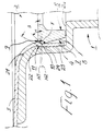
- figure 1
- is a section through a part of a floor drain with a device according to the invention;
- figure 2
- is a section through a floor drain according to figure 1 having an extension ring connected thereto;
- figure 3
- is a section through a lower portion of the extension ring of figure 2; and
- figure 4
- is a part of a plan view of the floor drain of figure 1 with a clamping ring mounted therein partially in section.
- In the drawings there is illustrated a
floor drain 1 into theinlet member 2 of which a floor covering 3, preferably a plastic floor mat, is inserted. This floor covering 3 shall be held closely against a downwardly directedwall 4 of theinlet member 2 by means of aclamping ring 5 mounted in saidinlet member 2. Thisclamping ring 5 is split (see fig. 4) and comprises aspring 6 which permits sufficient compression thereof in radial direction for inserting it into theinlet member 2. Thereafter, when theclamping ring 5 is released, thespring 6 will dilate or expand said clamping ring radially outwards until it engages the floor covering 3. Hereby, theclamping ring 5 will press the floor covering 3 in outwards direction against the downwardly directedwall 4 of theinlet member 2, such that the floor covering 3 closely engages saidwall 4. Clampingrings 5 of this type are described in detail in our SE patent specification No. 8802915-2. - The side 7 of the
clamping ring 5 facing outwards towards the floor covering 3 includes twosurfaces point 10 facing outwards towards the floor covering 3. The downwardly directedwall 4 of theinlet member 2 includes awall portion 11 which is directed downwards/outwards relative to theclamping ring 5 and thiswall portion 11 is at least partially situated on a somewhat higher level H1 than the level H2 of thepoint 10 of theclamping ring 5 in its operative position in theinlet member 2, i.e. when it engages theseat 2a in saidinlet member 2. - Furthermore, the angle α between the horizontal plane (here illustrated with the line H2 in fig. 1) and the
upper surface 9 of theclamping ring 5 is equal to or somewhat smaller than the angle β betweensaid wall portion 11 and the horizontal plane (here illustrated as the line H1 in fig. 1). It is hereby provided that thefloor drain 1 is located in its intended position relative to the horizontal plane; if thefloor drain 1 is located somewhat inclined relative to this intended position, the angles α and β will change correspondingly relative to the horizontal plane, but said relationship between these angles will remain unaltered. By means of thewall portion 11 and said relationship between the angles α and β, it is ensured that neither that part of the floor covering 3 located between saidwall portion 11 and thepoint 10 of theclamping ring 5 nor said clampingring 5 will glide upwards e.g. if the floor covering 3 shrinks, which results in a remaining sealing effect between said floor covering 3 and theinlet member 2. - As is apparent from fig. 1, the downwardly/outwardly directed
wall portion 11 is located on a somewhat higher level than thepoint 10 of the clamping ring 5 (in fig. 1 this difference in level corresponds with the distance between the levels H1 and H2). - The angle α between the upper surface of the
clamping ring 5 and the horizontal plane H2 preferably lies within a range of 10-55°. Preferably, the angle α is about 45°. Apoint 10 of a suitable shape is obtained if the angle γ between the upper andlower surfaces clamping ring 5 lies within a range of 100-140°. Preferably, this angle γ is about 120°. The downwardly/outwardly directedwall portion 11 defines with the horizontal plane H1 preferably an angle β within a range of 55-65°. Preferably, the angle β is about 60°. - The
inlet member 2 mentioned above may preferably also be used for mounting anextension ring 12 if the floor level is raised and one wish to maintain the existingfloor drain 1 but yet provide aninlet member 2 located in level with the raised floor level. Thisextension ring 12 can be snapped onto theinlet member 2 of the floor drain while saidextension ring 12 comprises a snap-inportion 13 which is intended to be moved at least partially beyond the downwardly/outwardly directedwall portion 11 until said snap-inportion 13 is snapped onto the inlet member 2 (see fig. 2). - The snap-in
portion 13 preferably includes apoint 14 which, when pressing down theextension ring 12 into theinlet member 2, is engageable with the downwardly/outwardly directedwall portion 11 or preferably with the downwardly directedwall 4 just beneath saidwall portion 11. Thepoint 14 is preferably provided at such a distance above thelower edge 15 of theextension ring 12 that theextension ring 12 in its operative function is clamped between theseat 2a and thewall portion 11 or the downwardly directedwall 4, just beneathsaid wall portion 11 depending on where thepoint 14 is engaged. This means that theextension ring 12, in its operative position, can not move in axial direction relative to thefloor drain 1. - The snap-in
portion 13 preferably comprises anouter side 16 with the same or similar shape as the outer side 7 of theclamping ring 5. Thus, the snap-inportion 13 may include anupper surface 17 with the same angle α to the horizontal plane as thesurface 9 of the clamping ring 5 (see fig. 3). Furthermore, theouter side 16 may have alower surface 18 and the angle between thesesurfaces corresponding surfaces clamping ring 5. In thelower surface 18 there may be provided agroove 19 for a sealing ring 20 which is adapted to provide a sealing between theinlet member 2 and the outer side of theextension ring 12. - For being able to provide as good and durable a sealing between the floor covering 3 on the new floor level and the
inlet member 2 of theextension ring 12, saidinlet member 2 has the same shape as theinlet member 2 of thefloor drain 1, i.e. comprises a downwardly/inwardly directedwall portion 11 and so on, and those parts of theinlet member 2 of theextension ring 12 which correspond with the same parts of theinlet member 2 of thefloor drain 1 have for the purpose of simplification received the same reference numerals in fig. 2. - It should be mentioned that the
inlet member 2 preferably comprises a downwardlybent surface 21, through which the floor covering 3 extends downwards towards the downwardly directedwall 4. This downwardlybent surface 21 can down below define aconstriction 22 of theinlet member 2 and the downwardly/outwardly directedwall portion 11 can be located just beneath this constriction 22 (see fig. 1). The downwardly/outwardly directedwall portion 11 preferably transforms into a vertically or substantially vertically directedsection 23 of the downwardly directedwall 4 and thissection 23 preferably has arough portion 24 situated on the same level H2 as thepoint 10 of theclamping ring 5. - The invention is not limited to the illustrated embodiment but may vary within the scope of the following claims. As alternative exemples it should be mentioned that the inlet member need not necessarily be circular and eventually neither the clamping ring. The clamping ring can also be of another type than shown.
Claims (6)
- Clamping device for floor drains including an inlet member (2) into which a floor covering (3) is insertable, whereby the floor covering (3) inserted into the inlet member (2) is arranged to engage a downwardly directed wall (4) of said inlet member (2),
whereby a clamping ring (5) is provided within the floor covering (3) inserted into the inlet member (2), said clamping ring (5) being arranged to press the floor covering (3) inserted into the inlet member (2) in a direction outwards against the downwardly directed wall (4) and said clamping ring (5) being split and provided with a spring (6) which is arranged to press said clamping ring (5) in a direction outwards against the floor covering (3),
whereby one side (7) of the clamping ring (5) facing outwards towards the floor covering (3) includes two surfaces (8, 9) extending at an angle relative to each other and together defining a point (10) facing outwards towards said floor covering (3),
whereby the downwardly directed wall (4) comprises a relative to the clamping ring (5) downwardly/outwardly directed wall portion (11) which at least partially is located on a higher level (H1) than the point (10) of the clamping ring (5) when said clamping ring (5) is situated in an operative position in the inlet member (2),
whereby an upper surface (9) of the two surfaces (8, 9) of the clamping ring (5) extending at an angle relative to each other defines an angle (α) with the horizontal plane (H2) which is equal to or preferably smaller than an angle (β) between the downwardly/outwardly directed wall portion (11) of the downwardly directed wall (4) and the horizontal plane (H1),
whereby the angle (α) between said upper surface (9) and the horizontal plane (H2) lies within a range of 10-55° and is preferably about 45°, and
whereby the surfaces (8, 9) of the clamping ring (5) extending relative to each other defines an angle (γ) lying within a range of 100-140°, said angle being preferably about 120°,
characterized in
that the downwardly/outwardly directed wall portion (11) defines with the horizontal plane (H1) an angle (β) lying within a range of 55-65°, said angle being preferably about 60°, and
that the spring (6) permits sufficient compression of the clamping ring (5) in radial direction for insertion of said clamping ring into the inlet member (2) until the point (10) thereof is located below the level (H1) of said wall portion (11), whereafter the spring (6) may dilate or expand the clamping ring (5) outwards in radial direction until said clamping ring engages the floor covering (3). - Device according to claim 1, characterized in that the inlet member (2) comprises a downwardly curved surface (21) which defines a constriction (22) of said inlet member (2), that the downwardly/outwardly directed wall portion (11) is situated beneath the constriction (22) and that the downwardly/outwardly directed wall portion (11) down below transforms into a vertically or substantially vertically directed section (23) of the downwardly directed wall (4), which section (23) preferably comprises a rough portion (24) located on the same level (H2) as the point (10) of the clamping ring (5).
- Device according to claim 1 or 2, whereby an extension ring (12) can be moved down into the inlet portion (2) of the floor drain (1), characterized in that the extension ring (12) can be snapped onto the inlet member (2) of the floor drain (1) while said extention ring (12) includes a snap-in portion (13) which is arranged to cooperate with the outwardly/downwardly directed wall portion (11) and which is adapted to be moved in downwards direction at least partially beyond said outwardly/downwardly directed wall portion (11) until the snap-in portion (13) is snapped in position.
- Device according to claim 3, characterized in that the snap-in portion (13) of the extension ring (12) has a point (14) for engaging the downwardly/outwardly directed wall portion (11) of the inlet member (2) or preferably a downwardly directed wall (4) of said inlet member (2) just beneath said wall portion (11).
- Device according to claim 4, characterized in that the point (14) of the snap-in portion (13) is provided at such a distance above a lower edge (15) on the extension ring (12) that said ring, in an operative position wherein it engages at seat (2a) in the inlet member (2), is clamped between said seat (2a) and the downwardly/outwardly directed wall portion (11) or that part of the downwardly directed wall (4) which is located just beneath said wall portion (11) engaged by said point (14).
- Device according to claims 3-5, whereby the extension ring (12) comprises an inlet member (2) into which a floor covering (3) is insertable, whereby the floor covering (3) inserted into the inlet member (2) is arranged to engage a downwardly directed wall (4) of said inlet member (2),
whereby a clamping ring (5) is provided within the floor covering (3) inserted into the inlet member (2) of the extension ring (12), said clamping ring (5) being adapted to press the floor covering (3) inserted into the inlet member (2) of the extension ring (12) in a direction outwards against the downwardly directed wall (4) and said clamping ring (5) being split and provided with a spring (6) which is adapted to press said clamping ring (5) in a direction outwards against the floor covering (3),
whereby one side (7) of the clamping ring (5) facing outwards towards the floor covering (3) includes two surfaces (8, 9) extending at an angle relative to each other and together defining a point (10) facing outwards towards said floor covering (3),
whereby the downwardly directed wall (4) comprises a relative to the clamping ring (5) downwardly/outwardly directed wall portion (11) which at least partially is located on a higher level (H1) that the point (10) of the clamping ring (5) when said clamping ring (5) is situated in an operative position in the inlet member (2),
whereby an upper surface (9) of the two surfaces (8, 9) extending at an angle relative to each other of the clamping ring (5), which is insertable into the inlet member (2) of the extension ring (12), defines an angle (α) with the horizontal plane (H2) which is equal to or preferably smaller than an angle (β) between the downwardly/outwardly directed wall portion (11) of the downwardly directed wall (4) and the horizontal plane (H1),
whereby the angle (α) between said upper surface (9) and the horizontal plane (H2) lies within a range of 10-55° and is preferably about 45°, and
whereby the surfaces (8, 9) of the clamping ring (5) extending relative to each other defines an angle (γ) lying within a range of 100-140°, said angle being preferably about 120°,
characterized in
that the downwardly/outwardly directed wall portion (11) defines with the horizontal plane (H1) an angle (β) lying within a range of 55-65°, said angle being preferably about 60°, and
that the spring (6) permits sufficient compression of the clamping ring (5) in radial direction for insertion of said clamping ring into the inlet member (2) of the extension ring (12) until the point (10) thereof is located below the level (H1) of said wall portion (11), whereafter the spring (6) may dilate or expand the clamping ring (5) outwards in radial direction until said clamping ring engages the floor covering (3).
Applications Claiming Priority (2)
| Application Number | Priority Date | Filing Date | Title |
|---|---|---|---|
| SE9100680 | 1991-03-07 | ||
| SE9100680A SE9100680L (en) | 1991-03-07 | 1991-03-07 | DEVICE ON FLOOR TOWNS |
Publications (2)
| Publication Number | Publication Date |
|---|---|
| EP0502493A1 EP0502493A1 (en) | 1992-09-09 |
| EP0502493B1 true EP0502493B1 (en) | 1994-12-21 |
Family
ID=20382090
Family Applications (1)
| Application Number | Title | Priority Date | Filing Date |
|---|---|---|---|
| EP92103668A Expired - Lifetime EP0502493B1 (en) | 1991-03-07 | 1992-03-04 | Clamping device for floor drains |
Country Status (7)
| Country | Link |
|---|---|
| EP (1) | EP0502493B1 (en) |
| AT (1) | ATE116026T1 (en) |
| DE (1) | DE69200932T2 (en) |
| DK (1) | DK0502493T3 (en) |
| FI (1) | FI95829C (en) |
| NO (1) | NO309533B1 (en) |
| SE (1) | SE9100680L (en) |
Cited By (1)
| Publication number | Priority date | Publication date | Assignee | Title |
|---|---|---|---|---|
| RU198187U1 (en) * | 2020-01-22 | 2020-06-23 | Общество с ограниченной ответственностью "ФАХМАНН РУССЛАНДА" | Roof drain funnel |
Families Citing this family (5)
| Publication number | Priority date | Publication date | Assignee | Title |
|---|---|---|---|---|
| NL9201790A (en) * | 1992-10-15 | 1994-05-02 | Johannes Adrianus Henricus Mar | Rainwater drain connector and method for its manufacture. |
| SE506914C2 (en) * | 1995-09-18 | 1998-03-02 | Sjoebo Bruk Ab | Transition device at floor wells |
| NL2001410C2 (en) * | 2008-03-27 | 2009-09-03 | Assenti Lux S A | Method, device, material layer and collection of parts for sealing a drain gutter. |
| NL2005842C2 (en) * | 2010-12-09 | 2012-06-12 | Easy Sanitairy Solutions Bv | VINYL GOOT. |
| DE102017125882A1 (en) * | 2017-11-06 | 2019-05-09 | Monier Roofing Components Gmbh | Rainwater harvesting |
Family Cites Families (5)
| Publication number | Priority date | Publication date | Assignee | Title |
|---|---|---|---|---|
| DE2507045A1 (en) * | 1975-02-19 | 1976-09-09 | Dallmer Helmuth Fa | Gutter inlet for flat roofs - incorporates clamping ring with socket, to clamp roofing foil |
| SE399451B (en) * | 1976-06-04 | 1978-02-13 | Spanberg B | DRAINAGE AT DRAINS |
| DE3007511C2 (en) * | 1980-02-28 | 1982-04-08 | Karl Heinz 3353 Bad Gandersheim Vahlbrauk | Process for liquid-exposed solid ceilings of buildings |
| DE3445186C2 (en) * | 1983-12-13 | 1986-04-17 | Eternit Ag, 1000 Berlin | Water inlet |
| SE461742B (en) * | 1988-08-17 | 1990-03-19 | Sjoebo Bruk Ab | COMPRESSION TO CLAMP DIFFERENT COATING MATERIAL AGAINST THE INSIDE OF A WELL |
-
1991
- 1991-03-07 SE SE9100680A patent/SE9100680L/en not_active Application Discontinuation
-
1992
- 1992-03-03 NO NO920821A patent/NO309533B1/en unknown
- 1992-03-04 EP EP92103668A patent/EP0502493B1/en not_active Expired - Lifetime
- 1992-03-04 FI FI920962A patent/FI95829C/en active IP Right Grant
- 1992-03-04 AT AT92103668T patent/ATE116026T1/en not_active IP Right Cessation
- 1992-03-04 DK DK92103668.7T patent/DK0502493T3/en active
- 1992-03-04 DE DE69200932T patent/DE69200932T2/en not_active Expired - Fee Related
Cited By (1)
| Publication number | Priority date | Publication date | Assignee | Title |
|---|---|---|---|---|
| RU198187U1 (en) * | 2020-01-22 | 2020-06-23 | Общество с ограниченной ответственностью "ФАХМАНН РУССЛАНДА" | Roof drain funnel |
Also Published As
| Publication number | Publication date |
|---|---|
| DK0502493T3 (en) | 1995-05-08 |
| NO920821D0 (en) | 1992-03-03 |
| EP0502493A1 (en) | 1992-09-09 |
| ATE116026T1 (en) | 1995-01-15 |
| FI95829B (en) | 1995-12-15 |
| NO920821L (en) | 1992-09-08 |
| FI95829C (en) | 1996-03-25 |
| DE69200932D1 (en) | 1995-02-02 |
| NO309533B1 (en) | 2001-02-12 |
| FI920962A7 (en) | 1992-09-08 |
| SE9100680D0 (en) | 1991-03-07 |
| DE69200932T2 (en) | 1995-06-08 |
| FI920962A0 (en) | 1992-03-04 |
| SE9100680L (en) | 1992-09-08 |
Similar Documents
| Publication | Publication Date | Title |
|---|---|---|
| EP0055003B1 (en) | A branch pipe connection | |
| AU6884094A (en) | Plug-in socket joint secured against sliding movement | |
| US8017870B2 (en) | Fastening device for a line | |
| GB2335951A (en) | Panel fixing clip comprising grommet, pin and flexible seal cap | |
| US6082782A (en) | Connection fitting having an axially protruding fastening projection | |
| CA2122204A1 (en) | Water Heater Stand | |
| GB2112486A (en) | Fastening device | |
| CA2191927A1 (en) | Joint Assembly | |
| US5040829A (en) | Hose coupling | |
| US5143469A (en) | Retention socket for a pivot | |
| US6227548B1 (en) | Seal for machine parts that reciprocate relative to one another | |
| EP0113054B1 (en) | Boltless restrained pipe joint | |
| EP0502493A1 (en) | Clamping device for floor drains | |
| GB2267857A (en) | Tool for venting hydraulic systems | |
| US20010040348A1 (en) | Pipe connecting gaskets | |
| JP3359966B2 (en) | Double floor floor panel support equipment | |
| US6354602B1 (en) | Assembly vent for boot/seal installation | |
| US4941707A (en) | Method for installing a cavity seal element inserted in a groove and an apparatus for setting a spacing of the groove | |
| EP1026330B1 (en) | Water seal for floor drains | |
| RU2161900C1 (en) | Vacuum cleaner telescopic suction pipe | |
| EP0789967B1 (en) | Fastening of picture tube in cabinet of tv receiver set | |
| EP0419493B1 (en) | Master cylinder and reservoir connection | |
| JP3450789B2 (en) | Hose joint retaining member and hose joint | |
| EP1054112A1 (en) | Device for floor drain | |
| JPS6232933Y2 (en) |
Legal Events
| Date | Code | Title | Description |
|---|---|---|---|
| PUAI | Public reference made under article 153(3) epc to a published international application that has entered the european phase |
Free format text: ORIGINAL CODE: 0009012 |
|
| AK | Designated contracting states |
Kind code of ref document: A1 Designated state(s): AT BE CH DE DK FR GB IT LI NL SE |
|
| 17P | Request for examination filed |
Effective date: 19930305 |
|
| 17Q | First examination report despatched |
Effective date: 19931025 |
|
| GRAA | (expected) grant |
Free format text: ORIGINAL CODE: 0009210 |
|
| AK | Designated contracting states |
Kind code of ref document: B1 Designated state(s): AT BE CH DE DK FR GB IT LI NL SE |
|
| REF | Corresponds to: |
Ref document number: 116026 Country of ref document: AT Date of ref document: 19950115 Kind code of ref document: T |
|
| REF | Corresponds to: |
Ref document number: 69200932 Country of ref document: DE Date of ref document: 19950202 |
|
| ITF | It: translation for a ep patent filed | ||
| ET | Fr: translation filed | ||
| REG | Reference to a national code |
Ref country code: DK Ref legal event code: T3 |
|
| PLBE | No opposition filed within time limit |
Free format text: ORIGINAL CODE: 0009261 |
|
| STAA | Information on the status of an ep patent application or granted ep patent |
Free format text: STATUS: NO OPPOSITION FILED WITHIN TIME LIMIT |
|
| 26N | No opposition filed | ||
| REG | Reference to a national code |
Ref country code: GB Ref legal event code: IF02 |
|
| PGFP | Annual fee paid to national office [announced via postgrant information from national office to epo] |
Ref country code: GB Payment date: 20050301 Year of fee payment: 14 Ref country code: DK Payment date: 20050301 Year of fee payment: 14 |
|
| PGFP | Annual fee paid to national office [announced via postgrant information from national office to epo] |
Ref country code: AT Payment date: 20050321 Year of fee payment: 14 |
|
| PGFP | Annual fee paid to national office [announced via postgrant information from national office to epo] |
Ref country code: CH Payment date: 20050329 Year of fee payment: 14 |
|
| PGFP | Annual fee paid to national office [announced via postgrant information from national office to epo] |
Ref country code: NL Payment date: 20050331 Year of fee payment: 14 |
|
| PGFP | Annual fee paid to national office [announced via postgrant information from national office to epo] |
Ref country code: BE Payment date: 20050422 Year of fee payment: 14 |
|
| PGFP | Annual fee paid to national office [announced via postgrant information from national office to epo] |
Ref country code: DE Payment date: 20050531 Year of fee payment: 14 |
|
| PG25 | Lapsed in a contracting state [announced via postgrant information from national office to epo] |
Ref country code: AT Free format text: LAPSE BECAUSE OF NON-PAYMENT OF DUE FEES Effective date: 20060304 Ref country code: GB Free format text: LAPSE BECAUSE OF NON-PAYMENT OF DUE FEES Effective date: 20060304 |
|
| PG25 | Lapsed in a contracting state [announced via postgrant information from national office to epo] |
Ref country code: CH Free format text: LAPSE BECAUSE OF NON-PAYMENT OF DUE FEES Effective date: 20060331 Ref country code: BE Free format text: LAPSE BECAUSE OF NON-PAYMENT OF DUE FEES Effective date: 20060331 Ref country code: LI Free format text: LAPSE BECAUSE OF NON-PAYMENT OF DUE FEES Effective date: 20060331 Ref country code: DK Free format text: LAPSE BECAUSE OF NON-PAYMENT OF DUE FEES Effective date: 20060331 |
|
| PGFP | Annual fee paid to national office [announced via postgrant information from national office to epo] |
Ref country code: IT Payment date: 20060331 Year of fee payment: 15 |
|
| PG25 | Lapsed in a contracting state [announced via postgrant information from national office to epo] |
Ref country code: NL Free format text: LAPSE BECAUSE OF NON-PAYMENT OF DUE FEES Effective date: 20061001 |
|
| PG25 | Lapsed in a contracting state [announced via postgrant information from national office to epo] |
Ref country code: DE Free format text: LAPSE BECAUSE OF NON-PAYMENT OF DUE FEES Effective date: 20061003 |
|
| REG | Reference to a national code |
Ref country code: DK Ref legal event code: EBP |
|
| REG | Reference to a national code |
Ref country code: CH Ref legal event code: PL |
|
| GBPC | Gb: european patent ceased through non-payment of renewal fee |
Effective date: 20060304 |
|
| NLV4 | Nl: lapsed or anulled due to non-payment of the annual fee |
Effective date: 20061001 |
|
| BERE | Be: lapsed |
Owner name: *SJOBO BRUK A.B. Effective date: 20060331 |
|
| PGFP | Annual fee paid to national office [announced via postgrant information from national office to epo] |
Ref country code: SE Payment date: 20090306 Year of fee payment: 18 |
|
| PG25 | Lapsed in a contracting state [announced via postgrant information from national office to epo] |
Ref country code: IT Free format text: LAPSE BECAUSE OF NON-PAYMENT OF DUE FEES Effective date: 20070304 |
|
| PGFP | Annual fee paid to national office [announced via postgrant information from national office to epo] |
Ref country code: FR Payment date: 20090316 Year of fee payment: 18 |
|
| EUG | Se: european patent has lapsed | ||
| REG | Reference to a national code |
Ref country code: FR Ref legal event code: ST Effective date: 20101130 |
|
| PG25 | Lapsed in a contracting state [announced via postgrant information from national office to epo] |
Ref country code: FR Free format text: LAPSE BECAUSE OF NON-PAYMENT OF DUE FEES Effective date: 20100331 |
|
| PG25 | Lapsed in a contracting state [announced via postgrant information from national office to epo] |
Ref country code: SE Free format text: LAPSE BECAUSE OF NON-PAYMENT OF DUE FEES Effective date: 20100305 |