EP3476011B1 - Feed-through terminal - Google Patents
Feed-through terminal Download PDFInfo
- Publication number
- EP3476011B1 EP3476011B1 EP17727255.6A EP17727255A EP3476011B1 EP 3476011 B1 EP3476011 B1 EP 3476011B1 EP 17727255 A EP17727255 A EP 17727255A EP 3476011 B1 EP3476011 B1 EP 3476011B1
- Authority
- EP
- European Patent Office
- Prior art keywords
- terminal
- feed
- wall opening
- housing
- fastening element
- Prior art date
- Legal status (The legal status is an assumption and is not a legal conclusion. Google has not performed a legal analysis and makes no representation as to the accuracy of the status listed.)
- Active
Links
- 238000003780 insertion Methods 0.000 claims description 20
- 230000037431 insertion Effects 0.000 claims description 20
- 230000013011 mating Effects 0.000 claims 1
- 239000004020 conductor Substances 0.000 description 13
- 238000009434 installation Methods 0.000 description 11
- 230000000903 blocking effect Effects 0.000 description 3
- 238000002347 injection Methods 0.000 description 1
- 239000007924 injection Substances 0.000 description 1
- 238000004519 manufacturing process Methods 0.000 description 1
- 239000000463 material Substances 0.000 description 1
- 230000001681 protective effect Effects 0.000 description 1
Images


Classifications
-
- H—ELECTRICITY
- H01—ELECTRIC ELEMENTS
- H01R—ELECTRICALLY-CONDUCTIVE CONNECTIONS; STRUCTURAL ASSOCIATIONS OF A PLURALITY OF MUTUALLY-INSULATED ELECTRICAL CONNECTING ELEMENTS; COUPLING DEVICES; CURRENT COLLECTORS
- H01R9/00—Structural associations of a plurality of mutually-insulated electrical connecting elements, e.g. terminal strips or terminal blocks; Terminals or binding posts mounted upon a base or in a case; Bases therefor
- H01R9/22—Bases, e.g. strip, block, panel
- H01R9/24—Terminal blocks
- H01R9/2408—Modular blocks
-
- H—ELECTRICITY
- H01—ELECTRIC ELEMENTS
- H01R—ELECTRICALLY-CONDUCTIVE CONNECTIONS; STRUCTURAL ASSOCIATIONS OF A PLURALITY OF MUTUALLY-INSULATED ELECTRICAL CONNECTING ELEMENTS; COUPLING DEVICES; CURRENT COLLECTORS
- H01R4/00—Electrically-conductive connections between two or more conductive members in direct contact, i.e. touching one another; Means for effecting or maintaining such contact; Electrically-conductive connections having two or more spaced connecting locations for conductors and using contact members penetrating insulation
- H01R4/28—Clamped connections, spring connections
- H01R4/48—Clamped connections, spring connections utilising a spring, clip, or other resilient member
- H01R4/4809—Clamped connections, spring connections utilising a spring, clip, or other resilient member using a leaf spring to bias the conductor toward the busbar
-
- H—ELECTRICITY
- H01—ELECTRIC ELEMENTS
- H01R—ELECTRICALLY-CONDUCTIVE CONNECTIONS; STRUCTURAL ASSOCIATIONS OF A PLURALITY OF MUTUALLY-INSULATED ELECTRICAL CONNECTING ELEMENTS; COUPLING DEVICES; CURRENT COLLECTORS
- H01R13/00—Details of coupling devices of the kinds covered by groups H01R12/70 or H01R24/00 - H01R33/00
- H01R13/73—Means for mounting coupling parts to apparatus or structures, e.g. to a wall
- H01R13/74—Means for mounting coupling parts in openings of a panel
- H01R13/741—Means for mounting coupling parts in openings of a panel using snap fastening means
- H01R13/743—Means for mounting coupling parts in openings of a panel using snap fastening means integral with the housing
-
- H—ELECTRICITY
- H01—ELECTRIC ELEMENTS
- H01R—ELECTRICALLY-CONDUCTIVE CONNECTIONS; STRUCTURAL ASSOCIATIONS OF A PLURALITY OF MUTUALLY-INSULATED ELECTRICAL CONNECTING ELEMENTS; COUPLING DEVICES; CURRENT COLLECTORS
- H01R9/00—Structural associations of a plurality of mutually-insulated electrical connecting elements, e.g. terminal strips or terminal blocks; Terminals or binding posts mounted upon a base or in a case; Bases therefor
- H01R9/22—Bases, e.g. strip, block, panel
- H01R9/24—Terminal blocks
- H01R9/26—Clip-on terminal blocks for side-by-side rail- or strip-mounting
- H01R9/2616—End clamping members
-
- H—ELECTRICITY
- H01—ELECTRIC ELEMENTS
- H01R—ELECTRICALLY-CONDUCTIVE CONNECTIONS; STRUCTURAL ASSOCIATIONS OF A PLURALITY OF MUTUALLY-INSULATED ELECTRICAL CONNECTING ELEMENTS; COUPLING DEVICES; CURRENT COLLECTORS
- H01R13/00—Details of coupling devices of the kinds covered by groups H01R12/70 or H01R24/00 - H01R33/00
- H01R13/62—Means for facilitating engagement or disengagement of coupling parts or for holding them in engagement
- H01R13/639—Additional means for holding or locking coupling parts together, after engagement, e.g. separate keylock, retainer strap
- H01R13/6395—Additional means for holding or locking coupling parts together, after engagement, e.g. separate keylock, retainer strap for wall or panel outlets
Description
Die Erfindung betrifft eine Durchführungsklemme zur Montage in einer Wandöffnung in einer Gehäusewand, mit einem einen Innenabschnitt und einen Außenabschnitt aufweisenden Klemmengehäuse, wobei in dem Innenabschnitt und in dem Außenabschnitt jeweils ein Anschlusselement angeordnet ist, und mit einer Befestigungseinrichtung, die aus einer gelösten Stellung in eine Befestigungsstellung, in der das Klemmengehäuse in der Wandöffnung befestigt ist, verbringbar ist, wobei bei der Montage der Durchführungsklemme der Innenabschnitt von der Außenseite durch die Wandöffnung durchsteckbar ist.The invention relates to a feedthrough terminal for mounting in a wall opening in a housing wall, with a terminal housing having an inner section and an outer section, wherein a connection element is arranged in the inner section and in the outer section, and with a fastening device which can be moved from a released position into a fastening position in which the terminal housing is fastened in the wall opening, wherein when mounting the feedthrough terminal the inner section can be pushed through the wall opening from the outside.
Elektrische Reihenklemmen sind seit Jahrzehnten bekannt und werden millionenfach bei der Verdrahtung elektrischer Anlagen und Geräte verwendet. Die Klemmen werden häufig auf Tragschienen aufgerastet, welche ihrerseits in einer Mehrzahl in einem Schaltschrank angeordnet sein können. Daneben können die Reihenklemmen aber auch alleine oder in der Regel zu mehreren als Klemmenblock in einer Wandöffnung einer Gehäusewand, insbesondere in einer Öffnung in einer Schaltschrankwand, befestigt sein. Dies hat den Vorteil, dass die eine Seite der Klemmen, die Bedienerseite bzw. Vorderseite, von außerhalb des Schaltschranks zugänglich ist, ohne dass der Schaltschrank geöffnet werden muss. Die andere Seite der Klemme, die Anschlussseite bzw. Rückseite, ist dagegen nur bei geöffneten Schaltschrank zugänglich.Electrical terminal blocks have been around for decades and are used millions of times in the wiring of electrical systems and devices. The terminal blocks are often snapped onto mounting rails, which in turn can be arranged in a plurality of them in a control cabinet. In addition, the terminal blocks can also be attached alone or usually in several as a terminal block in a wall opening in a housing wall, in particular in an opening in a control cabinet wall. This has the advantage that one side of the terminals, the operator side or front, is accessible from outside the control cabinet without having to open the control cabinet. The other side of the terminal, the connection side or rear, is only accessible when the control cabinet is open.
Als Anschlusselemente werden in Reihenklemmen insbesondere Schraubklemmen, Zugfederklemmen oder Schenkelfederklemmen verwendet. Das Klemmprinzip bei Zugfederklemmen ist ähnlich dem der Schraubtechnik. Während bei der Schraubklemme eine Zughülse durch die Betätigung der Klemmschraube den Leiter gegen den Strombalken zieht, wird bei der Zugfederklemme diese Aufgabe von der Zugfeder übernommen. Bei Schenkelfederklemmen wird dagegen der abisolierte Leiter vom Klemmschenkel der Feder gegen einen Strombalken gedrückt. Schenkelfederklemmen weisen dabei den Vorteil auf, dass ein abisolierter starrer Leiter direkt ohne Werkzeug an die Klemme angeschlossen werden kann, indem der Leiter in die Klemmstelle zwischen dem Ende des Klemmschenkels und dem Strombalken eingesteckt wird. Daneben können als Anschlusselemente aber auch Anschlussstifte oder Anschlussbuchsen verwendet werden, an die dann korrespondierende Anschlussbuchsen bzw. Anschlussstifte angeschlossen werden können.Screw terminals, tension spring terminals or leg spring terminals are used as connection elements in series terminals. The clamping principle of tension spring terminals is similar to that of screw technology. While in screw terminals a tension sleeve pulls the conductor against the current bar by operating the clamping screw, in tension spring terminals this task is performed by the tension spring. In leg spring terminals, on the other hand, the stripped conductor is pressed against a current bar by the clamping leg of the spring. Leg spring terminals have the advantage that a stripped rigid conductor can be connected directly to the terminal without tools by inserting the conductor into the clamping point between the end of the clamping leg and the current bar. In addition, connection pins or Connection sockets can be used, to which corresponding connection sockets or connection pins can then be connected.
Elektrische Reihenklemmen sind häufig Verbindungsklemmen, so dass sie mindestens zwei Anschlusselemente aufweisen, die elektrisch leitend miteinander verbunden sind, in der Regel über einen im Klemmengehäuse angeordneten Strombalken. Neben diesem Grundtyp der Reihenklemmen, der häufig auch als Durchgangsklemme bezeichnet wird, gibt es eine Vielzahl von unterschiedlichen Reihenklemmentypen, die speziell an die jeweiligen Anwendungsfälle angepasst sind. Als Beispiel seien Schutzleiterklemmen, Trennklemmen und Installationsklemmen genannt. Unabhängig von der Art der Klemme und den in der Klemme verwendeten Anschlusselementen ist bei Reihenklemmen, die in einer Wandöffnung befestigt werden, sogenannten Durchführungsklemmen, die einfache Montage und sicher mechanische Fixierung der Klemmen in der Wandöffnung von besonderer Bedeutung, wozu aus dem Stand der Technik verschiedene Befestigungsvorrichtungen bekannt sind.Electrical terminal blocks are often connecting terminals, meaning that they have at least two connection elements that are electrically connected to one another, usually via a current bar arranged in the terminal housing. In addition to this basic type of terminal block, which is often also referred to as a feed-through terminal, there are a large number of different terminal block types that are specially adapted to the respective application. Examples include protective conductor terminals, isolating terminals and installation terminals. Regardless of the type of terminal and the connection elements used in the terminal, the simple assembly and secure mechanical fixation of the terminals in the wall opening is of particular importance for terminal blocks that are attached to a wall opening, so-called feed-through terminals, for which various fastening devices are known from the state of the art.
Aus der
Auch die
Die
Die
Die
Der vorliegenden Erfindung liegt daher die Aufgabe zugrunde, eine Befestigungsmöglichkeit für Durchführungsklemmen sowie für einen aus mehreren Durchführungsklemmen bestehenden Klemmenblock zur Verfügung zu stellen, die bei einer einfachen Betätigung eine sichere Befestigung der Durchführungsklemme in der Wandöffnung gewährleistet. Darüber hinaus soll sich der von der Durchführungsklemme benötigte Bauraum durch die Befestigungseinrichtung möglichst nicht oder nur geringfügig vergrößern.The present invention is therefore based on the object of providing a fastening option for feedthrough terminals and for a terminal block consisting of several feedthrough terminals, which ensures secure fastening of the feedthrough terminal in the wall opening with a simple operation. In addition, the installation space required by the feedthrough terminal should not be increased or only increased slightly by the fastening device.
Diese Aufgabe ist bei der eingangs beschriebenen Durchführungsklemme mit den Merkmalen des Patentanspruchs 1 dadurch gelöst, dass die Befestigungseinrichtung ein federndes Befestigungselement und ein schwenkbares Betätigungsteil aufweist, dass mit dem Befestigungselement zusammenwirken kann. Das Befestigungselement und das Betätigungsteil sind dabei beide mit dem Klemmengehäuse verbunden, so dass keine separaten Bauteile, die bei der Montage verloren gehen können, vorgesehen sind. Das Befestigungselement ist mit seinem ersten Ende am Außenabschnitt des Klemmengehäuses befestigt, während es mit seinem zweiten, freien Ende im montierten Zustand der Durchführungsklemme in die Wandöffnung hineinragt. Am zweiten Ende des Befestigungselements ist dabei eine Klemmfläche ausgebildet, die in der Befestigungsstellung gegen eine Innenkante der Wandöffnung wirkt. Das Betätigungsteil ist über einen flexiblen Verbindungssteg mit dem Klemmengehäuse verbunden, so dass es aus einer ersten Position in eine zweite Position verschwenkbar ist. In der zweiten Position des Betätigungsteils ist das Befestigungselement durch das Betätigungsteil ausgelenkt, so dass das zweite Ende des Befestigungselements im montierten Zustand der Durchführungsklemme mit seiner Klemmfläche gegen die Innenkante der Wandöffnung drückt.This object is achieved in the feedthrough terminal described at the outset with the features of
Die erfindungsgemäße Durchführungsklemme unterscheidet sich zunächst dadurch von den aus dem Stand der Technik bekannten Durchführungsklemmen, dass die Befestigungseinrichtung keine separaten Bauteile, wie einen Schieber oder einen Rastbügel, aufweist, die zum einen den von der Durchführungsklemme benötigten Bauraum vergrößern, zum anderen bei der Montage verloren gehen können. Bei der erfindungsgemäßen Durchführungsklemme sind die beiden Elemente der Befestigungseinrichtung, das federnde Befestigungselement und das schwenkbare Betätigungsteil beide mit dem Klemmengehäuse verbunden und somit in die Durchführungsklemme integriert. Dadurch besteht die Möglichkeit, bei einem aus mehreren Durchführungsklemmen zusammengesetzten Klemmenblock jede Durchführungsklemme einzeln in der Wandöffnung zu fixieren. In der Regel kann es jedoch ausreichend sein, wenn bei einem aus mehreren Durchführungsklemmen bestehenden Klemmenblock nur die Befestigungseinrichtungen eines Teils der Durchführungsklemmen in die Befestigungsstellung verbracht werden, um den Klemmenblock insgesamt sicher in der Wandöffnung zu fixieren.The feedthrough terminal according to the invention differs from the feedthrough terminals known from the prior art in that the fastening device does not have any separate components, such as a slide or a locking bracket, which on the one hand increase the installation space required by the feedthrough terminal and on the other hand can get lost during assembly. In the feedthrough terminal according to the invention, the two elements of the fastening device, the spring fastening element and the pivoting actuating part, are both connected to the terminal housing and thus integrated into the feedthrough terminal. This makes it possible to fix each feedthrough terminal individually in the wall opening in a terminal block composed of several feedthrough terminals. As a rule, however, it can be sufficient if only the fastening devices of some of the feedthrough terminals are brought into the fastening position in order to fix the terminal block as a whole securely in the wall opening.
Damit die Durchführungsklemme bei der Montage in der Wandöffnung stets eine definierte Position aufweist, ist am Außenabschnitt des Klemmengehäuses vorzugsweise ein Anschlag ausgebildet, der im montierten Zustand der Durchführungsklemme an der die Wandöffnung begrenzenden Gehäusewand anliegt. Durch den Anschlag wird somit die Position vorgegeben, bis zu der die Durchführungsklemme bei der Montage in die Wandöffnung eingesteckt bzw. eingeschwenkt werden kann. Durch den Anschlag ist die Durchführungsklemme darüber hinaus in der Befestigungsstellung des Befestigungselements zusätzlich auch in horizontaler Richtung in der Wandöffnung festgelegt.To ensure that the feedthrough terminal always has a defined position when installed in the wall opening, a stop is preferably formed on the outer section of the terminal housing, which rests against the housing wall bordering the wall opening when the feedthrough terminal is installed. The stop thus specifies the position up to which the feedthrough terminal can be inserted or swiveled into the wall opening during installation. The stop also fixes the feedthrough terminal in the wall opening in the fastening position of the fastening element in a horizontal direction.
Gemäß einer weiteren besonders bevorzugten Ausgestaltung der erfindungsgemäßen Durchführungsklemme ist am Klemmengehäuse auf der der Klemmfläche des Betätigungsteils gegenüberliegenden Seite eine Einlegeschräge ausgebildet, mit der das Klemmengehäuse im montierten Zustand der Durchführungsklemme auf der unteren Innenkante der Wandöffnung aufsitzt. Die Durchführungsklemme wird dadurch im montierten Zustand nicht nur durch das Andrücken der Klemmfläche des Befestigungselements gegen die obere Innenkante der Wandöffnung gehalten, sondern zusätzlich auch dadurch fixiert, dass das Klemmengehäuse in vertikaler Richtung mit seiner Einlegeschräge gegen die untere Innenkante der Wandöffnung gedrückt wird.According to another particularly preferred embodiment of the feedthrough terminal according to the invention, an insertion bevel is formed on the terminal housing on the side opposite the clamping surface of the actuating part, with which the terminal housing sits on the lower inner edge of the wall opening when the feedthrough terminal is mounted. In the mounted state, the feedthrough terminal is not only held by pressing the clamping surface of the fastening element against the upper inner edge of the wall opening, but is also fixed in place by that the terminal housing is pressed vertically with its insertion slope against the lower inner edge of the wall opening.
Darüber hinaus gewährleistet die Ausbildung der Einlegeschräge an der Unterseite des Klemmengehäuses auch eine sichere Vormontage der Durchführungsklemme in der Wandöffnung, ohne dass die Gefahr besteht, dass die Durchführungsklemme aus der Wandöffnung herausfällt, wenn das Befestigungselement noch nicht durch das Betätigungsteil in die Befestigungsstellung verbracht worden ist. Hierzu wird die Durchführungsklemme in die Wandöffnung eingeschwenkt und anschließend auf die Einlegeschräge abgesenkt. Durch entsprechende Dimensionierung des Innenabschnitts des Klemmengehäuses wird dabei ein Herausfallen der Durchführungsklemme verhindert, auch wenn die Klemmfläche des zweiten Endes des Befestigungselements noch nicht mit der Innenkante der Wandöffnung zusammenwirkt. Die Ausbildung der Einlegeschräge ermöglicht darüber hinaus eine Montage der Durchführungsklemme in Wandöffnungen von Gehäusewänden, die - in gewissen Grenzen - unterschiedliche Materialstärken aufweisen.In addition, the design of the insertion slope on the underside of the terminal housing also ensures safe pre-assembly of the feed-through terminal in the wall opening, without the risk of the feed-through terminal falling out of the wall opening if the fastening element has not yet been moved into the fastening position by the actuating part. To do this, the feed-through terminal is swiveled into the wall opening and then lowered onto the insertion slope. By appropriately dimensioning the inner section of the terminal housing, the feed-through terminal is prevented from falling out, even if the clamping surface of the second end of the fastening element does not yet interact with the inner edge of the wall opening. The design of the insertion slope also enables the feed-through terminal to be installed in wall openings of housing walls that - within certain limits - have different material thicknesses.
Um eine dauerhafte und sichere Fixierung der Durchführungsklemme in einer Wandöffnung zu gewährleisten, ist das Betätigungsteil in seiner zweiten Position, in der es das Befestigungselement auslenkt, so dass dessen Klemmfläche gegen die obere Innenkante der Wandöffnung drückt, fixierbar. Dies wird vorteilhafterweise dadurch erzielt, dass das Befestigungselement an seinem zweiten Ende auf der der Klemmfläche gegenüberliegenden Fläche, d. h. auf der dem Betätigungsteil zugewandten Fläche, eine Verzahnung und das Betätigungsteil auf seiner dem Befestigungselement zugewandten Oberfläche eine korrespondierende Gegenverzahnung aufweist. Dadurch wird ein ungewolltes Zurückschwenken des Betätigungsteils aus seiner zweiten Position in die erste Position verhindert. Durch die beispielsweise durch entsprechende Rippen gewährleistete Verzahnung ist darüber hinaus sichergestellt, dass sich die Fixierung der Durchführungsklemme in einer Wandöffnung auch bei Vibrationen nicht löst oder lockert. Um eine sichere und dauerhafte Fixierung der Durchführungsklemme in einer Wandöffnung zu gewährleisten, weist die Klemmfläche des Betätigungselements vorzugsweise zusätzlich eine Rutschsicherung auf, wozu die Klemmfläche beispielsweise Rippen oder entsprechende Vorsprünge oder Noppen aufweisen kann.In order to ensure that the feedthrough terminal is permanently and securely fixed in a wall opening, the actuating part can be fixed in its second position, in which it deflects the fastening element so that its clamping surface presses against the upper inner edge of the wall opening. This is advantageously achieved in that the fastening element has a toothing on its second end on the surface opposite the clamping surface, i.e. on the surface facing the actuating part, and the actuating part has a corresponding counter toothing on its surface facing the fastening element. This prevents the actuating part from accidentally pivoting back from its second position to the first position. The toothing, which is ensured, for example, by corresponding ribs, also ensures that the fixation of the feedthrough terminal in a wall opening does not come loose or become loose even in the event of vibrations. In order to ensure that the feedthrough terminal is securely and permanently fixed in a wall opening, the clamping surface of the actuating element preferably also has an anti-slip device, for which purpose the clamping surface can have, for example, ribs or corresponding projections or knobs.
Damit das Betätigungsteil einfach aus seiner ersten Position in seine zweite Position und insbesondere auch wieder aus der zweiten, verrasteten Position zurück in die erste, gelöste Position verschwenkt werden kann, weist das Betätigungsteil an seinem freien Ende vorzugsweise eine Einstecköffnung für ein Betätigungswerkzeug auf. Bei dem Betätigungswerkzeug kann es sich beispielsweise um einem Schraubendreher handeln, dessen Spitze zum Verschwenken des Betätigungsteils in die Einstecköffnung eingeführt werden kann. Dadurch ist auch ein kleines Betätigungsteil von einem Monteur einfach und sicher aus seiner ersten Position in seine zweite Position und umgekehrt verschwenkbar.So that the actuating part can easily be moved from its first position to its second position and in particular also from the second, locked position can be pivoted back into the first, released position, the actuating part preferably has an insertion opening for an actuating tool at its free end. The actuating tool can be, for example, a screwdriver, the tip of which can be inserted into the insertion opening to pivot the actuating part. This means that even a small actuating part can be pivoted easily and safely by a fitter from its first position to its second position and vice versa.
In der Regel wird die erfindungsgemäße Durchführungsklemme nicht alleine in einer Wandöffnung befestigt, auch wenn dies grundsätzlich ohne Weiteres möglich ist. Zumeist bilden jedoch mehrere derartige Durchführungsklemmen zusammen einen Klemmenblock, wozu die scheibenförmigen Durchführungsklemmen miteinander verbunden, insbesondere miteinander verrastet sind. Ein derart gebildeter Klemmenblock kann dabei einfach dadurch in einer entsprechend dimensionierten Wandöffnung fixiert werden, dass die Befestigungselemente einzelner Durchführungsklemmen oder aller Durchführungsklemmen mittels der jeweiligen Betätigungsteile in die Befestigungsstellung verbracht werden.As a rule, the feedthrough terminal according to the invention is not fastened alone in a wall opening, even if this is basically possible without any problems. In most cases, however, several such feedthrough terminals together form a terminal block, for which purpose the disk-shaped feedthrough terminals are connected to one another, in particular locked together. A terminal block formed in this way can be fixed in a correspondingly dimensioned wall opening simply by moving the fastening elements of individual feedthrough terminals or all feedthrough terminals into the fastening position using the respective actuating parts.
Um die einzelnen Durchführungsklemmen mechanisch zu einem Klemmenblock miteinander zu verbinden, werden die Durchführungsklemmen in der Regel über an den Klemmengehäusen ausgebildete Rastelement zusammengerastet. Die Rastelemente bestehen dabei vorzugsweise aus auf der einen Seite der Klemmengehäuse angeordneten Rastzapfen und auf der anderen Seite der Klemmengehäuse ausgebildete korrespondierende Rastausnehmungen.In order to mechanically connect the individual feed-through terminals to form a terminal block, the feed-through terminals are usually snapped together using locking elements on the terminal housings. The locking elements preferably consist of locking pins arranged on one side of the terminal housing and corresponding locking recesses on the other side of the terminal housing.
Gemäß einer vorteilhaften Ausgestaltung des Klemmenblocks weist dieser neben einer Mehrzahl von Durchführungsklemmen noch zwei Abschlusselemente auf, die an den beiden Stirnseiten des Klemmenblocks befestigt sind. Im Gehäuse der Abschlusselemente ist dabei jeweils eine Einlegeschräge ausgebildet, mit der die Gehäuse im montierten Zustand des Klemmenblocks auf der unteren Innenkante der Wandöffnung aufsitzen. Die Einlegeschrägen in den Abschlusselementen sind dabei so angeordnet, dass sie mit den Einlegeschrägen in den Klemmengehäusen der Durchführungsklemmen in einer Flucht liegen. Die Abschlusselemente dienen dabei auch als eine Art Gehäusedeckel für die äußeren Durchführungsklemmen des Klemmenblocks, so dass die in den Klemmengehäusen der Durchführungsklemmen angeordneten leitenden Bauteile, die Anschlusselemente und die Stromschiene, gegen Berührung gesichert sind.According to an advantageous embodiment of the terminal block, in addition to a plurality of feedthrough terminals, it also has two end elements that are attached to the two front sides of the terminal block. In the housing of the end elements, an insertion bevel is formed, with which the housings sit on the lower inner edge of the wall opening when the terminal block is assembled. The insertion bevels in the end elements are arranged in such a way that they are aligned with the insertion bevels in the terminal housings of the feedthrough terminals. The end elements also serve as a type of housing cover. for the external feed-through terminals of the terminal block, so that the conductive components arranged in the terminal housings of the feed-through terminals, the connection elements and the busbar, are protected against contact.
Im Einzelnen gibt es nun eine Vielzahl von Möglichkeiten, die erfindungsgemäße Durchführungsklemme bzw. den Klemmenblock auszugestalten und weiterzubilden. Dazu wird verwiesen sowohl auf die den Patentansprüchen 1 und 9 nachgeordneten Patentansprüche, als auch auf die nachfolgende Beschreibung eines bevorzugten Ausführungsbeispiels in Verbindung mit der Zeichnung. In der Zeichnung zeigen
- Fig. 1
- eine erfindungsgemäße Durchführungsklemme von der Seite,
- Fig. 2
- die Durchführungsklemme gemäß
Fig. 1 mit einem eingesteckten Betätigungswerkzeug, im montierten Zustand, - Fig. 3
- eine vergrößerte Darstellung eines Teils der Durchführungsklemme gemäß
Fig. 2 , mit einem Teil einer Gehäusewand, - Fig. 4
- die Montage eines Klemmenblocks in einer Wandöffnung, in vier Schritten, von der Seite,
- Fig. 5
- ein erfindungsgemäßer Klemmenblock, bestehend aus mehreren Durchführungsklemmen und zwei Abschlusselementen, schräg von der Rückseite, und
- Fig. 6
- den Klemmenblock gemäß
Fig. 5 , schräg von der Vorderseite.
- Fig.1
- a feedthrough terminal according to the invention from the side,
- Fig.2
- the feedthrough terminal according to
Fig.1 with an inserted operating tool, in the assembled state, - Fig.3
- an enlarged view of a part of the feed-through terminal according to
Fig.2 , with part of a housing wall, - Fig.4
- the installation of a terminal block in a wall opening, in four steps, from the side,
- Fig.5
- a terminal block according to the invention, consisting of several feed-through terminals and two termination elements, diagonally from the rear, and
- Fig.6
- the terminal block according to
Fig.5 , diagonally from the front.
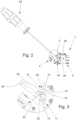
Die
Im Klemmengehäuse 6, das in der Regel als Kunststoffspritzteil ausgebildet ist, sind zwei Anschlusselemente 7, 8 angeordnet, durch die jeweils ein elektrischer Leiter an die Durchführungsklemme 1 angeschlossen werden kann. Bei der in den Figuren dargestellten Durchführungsklemme 1 sind als Anschlusselemente 7, 8 zwei Schenkelfedern vorgesehen, durch die jeweils ein anzuschließender Leiter gegen eine Stromschiene 9 gneklemmt wird. Mittels der beiden Schenkelfedern 7, 8 können zwei Leiter so über den Stromschiene 9 elektrisch leitend miteinander verbunden werden.In the
Zur Befestigung der Durchführungsklemme 1 in der Wandöffnung 2 weist die Durchführungsklemme 1 eine Befestigungseinrichtung auf, die aus einem federnden Befestigungselement 10 und einem schwenkbaren Betätigungsteil 11 besteht. Das als eine Art Federarm ausgebildete Befestigungselement 10 ist mit seinem ersten Ende 12 derart am Außenabschnitt 5 des Klemmengehäuses 6 befestigt, dass das zweite, freie Ende 13 des Befestigungselements 10 im montierten Zustand der Durchführungsklemme 1 in die Wandöffnung 2 hineinragt bzw. etwas durch die Wandöffnung 2 hindurchragt, wie dies insbesondere aus
Das keilförmige Betätigungsteil 11 ist über einen flexiblen Verbindungssteg 15 mit dem Klemmengehäuse 6 verbunden, so dass das Betätigungsteil 11 aus einer in
Der Außenabschnitt 5 des Klemmengehäuses 6 weist einen Anschlag 17 auf, der im montierten Zustand der Durchführungsklemme 1 an der Außenseite der die Wandöffnung 2 umgebenden Gehäusewand 3 anstößt. Durch den Anschlag 17 ist somit vorgegeben, wie weit die Durchführungsklemme 1 bei der Montage in die Wandöffnung 2 eingesteckt bzw. eingeschwenkt werden kann. Außerdem ist am Klemmengehäuse 6, auf der der Klemmfläche 14 des Betätigungsteils 10 gegenüberliegenden Seite eine Einlegeschräge 18 ausgebildet, mit der das Klemmengehäuse 6 im montierten Zustand der Durchführungsklemme auf der unteren Innenkante 19 der Wandöffnung 2 aufsitzt (
Zur Gewährleistung einer dauerhaften und sicheren Fixierung der Durchführungsklemme 1 in der Wandöffnung 2 weist die Klemmfläche 14 des Befestigungselements 10 eine Rutschsicherung 20 auf, die durch mehrere an der Klemmfläche 14 ausgebildete Rippen gebildet sein kann. Außerdem weist das Befestigungselement 10 an seinem zweiten Ende 13 auf der der Klemmfläche 14 gegenüberliegenden Fläche eine Verzahnung 21 und das Betätigungsteil 11 auf seiner dem Befestigungselement 10 zugewandten Oberfläche eine korrespondierende Gegenverzahnung 22 auf. Dadurch ist sichergestellt, dass kein ungewolltes Zurückschwenken des Betätigungsteils 11 aus seiner zweiten, verrasteten Position erfolgt. Damit ist auch gewährleistet, dass die Klemmfläche 14 des Befestigungselements 10 dauerhaft gegen die obere Innenkante 16 der Wandöffnung 2 gepresst wird, so dass es nicht zu einem ungewollten Lösen oder Verrutschen der Durchführungsklemme 1 in der Wandöffnung 2 kommt.To ensure permanent and secure fixation of the
Um das Betätigungsteil 11 auch bei relativ kleinen Abmessungen der Durchführungsklemme 1 einfach aus der ersten Position in die zweite Position verschwenken zu können, weist das Betätigungsteil 11 an seinem freien Ende eine Einstecköffnung 23 auf, in die die Spitze eines Schraubendrehers 24 als Betätigungswerkzeug eingesteckt werden kann. Mit Hilfe des Schraubendrehers 24 kann das Betätigungsteil 11 auch aus der verrasteten zweiten Position gelöst werden, so dass im Bedarfsfall eine Durchführungsklemme 1 auch wieder aus der Wandöffnung 2 gelöst werden kann.In order to be able to easily pivot the
Wie insbesondere aus der vergrößerten Darstellung gemäß
Zur einfachen Montage und Handhabung der Durchführungsklemme ist außerdem am Außenabschnitt 5 des Klemmengehäuses 6 auf zwei einander gegenüberliegenden Seiten jeweils eine Griffmulde 26 ausgebildet, so dass die Durchführungsklemme 1 bzw. das Klemmengehäuse 6 von einem Monteur einfach mit zwei Fingern gehalten werden kann. In den Griffmulden 26 können dabei als Rutschsicherung entsprechende Rippen ausgebildet sein, wie dies aus
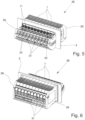
Die
Die Montage eines Klemmenblocks 28 in einer Wandöffnung 2 wird nachfolgend anhand der
Anschließend wird der Klemmenblock 28 entgegen dem Uhrzeigersinn verschwenkt, bis er sich in der in
Die
Claims (10)
- Feed-through terminal (1) for mounting in a wall opening (2) in a housing wall (3), with a terminal housing (6) having an inner section (4) and an outer section (5), wherein a connecting element (7, 8) is arranged in the inner section (4) and in the outer section (5) in each case, and with a fastening device which can be moved from a released position into a fastening position in which the terminal housing (6) is fastened in the wall opening (2), wherein the inner section (4) can be pushed through the wall opening (2) from the outside when the feed-through terminal (1) is mounted,wherein the fastening device has a resilient fastening element (10) and a pivotable actuating part (11),wherein the fastening element (10) is fastened with its first end (12) to the outer section (5) of the terminal housing (6) and projects with its second, free end (13) from the outside into the wall opening (2) in the mounted state of the feed-through terminal (1), wherein a clamping surface (14) is designed at the second end (13) of the fastening element (10),wherein the actuating part (11) is connected to the terminal housing (6) via a flexible connecting bar (15) and can be pivoted from a first position into a second position, andwherein in the second position of the actuating part (11), the fastening element (10) is deflected, so that in the mounted state of the feed-through terminal (1) the second end (13) of the fastening element (10) acts with its clamping surface (14) against an inner edge (16) of the wall opening (2) and wherein in the second position of the actuating part (11), the fastening element (10) is deflected by the actuating part (11).
- Feed-through terminal (1) according to claim 1, characterized in that a stop (17) is designed on the outer section (5) of the terminal housing (6), which stop is present on the housing wall (3) delimiting the wall opening (2) when the feed-through terminal (1) is mounted.
- Feed-through terminal (1) according to claim 1 or 2, characterized in that a placement bevel (18) is designed on the terminal housing (6) on the side opposite the clamping surface (14) of the actuating part (11), with which the terminal housing (6) rests on the lower inner edge (19) of the wall opening (2) when the feed-through terminal (1) is mounted.
- Feed-through terminal (1) according to any one of claims 1 to 3, characterized in that the clamping surface (14) of the fastening element (10) has an anti-slip safeguard (20).
- Feed-through terminal (1) according to any one of claims 1 to 4, characterized in that the fastening element (10) has toothing (21) at its second end (13) on the surface opposite the clamping surface (14) and the actuating part (11) has corresponding mating toothing (22) on its surface facing the fastening element (10).
- Feed-through terminal (1) according to any one of claims 1 to 5, characterized in that the actuating part (11) has an insertion opening (23) for an actuating tool (24) at its free end.
- Feed-through terminal (1) according to any one of claims 1 to 6, characterized in that an insertion bevel (25) is designed at the second end (13) of the fastening element (10), which projects through the wall opening (2) when the feed-through terminal (1) is mounted.
- Feed-through terminal (1) according to any one of claims 1 to 7, characterized in that recessed grips (26) are designed on the outer section (5) of the terminal housing (6) on two opposite sides.
- Terminal block (28) consisting of a plurality of feed-through terminals (1) according to any one of claims 1 to 8, arranged next to each other and connected to each other.
- Terminal block (28) according to claim 9, characterized in that a respective end element (29) is fastened to both end faces of the terminal block (28), wherein a placement bevel (30) is designed in the housing of the end elements (29) in each case, with which the housings sit on the lower inner edge (19) of the wall opening (2) in the assembled state of the terminal block (28).
Applications Claiming Priority (2)
| Application Number | Priority Date | Filing Date | Title |
|---|---|---|---|
| LU93126A LU93126B1 (en) | 2016-06-28 | 2016-06-28 | Through terminal |
| PCT/EP2017/063686 WO2018001682A1 (en) | 2016-06-28 | 2017-06-06 | Leadthrough terminal |
Publications (2)
| Publication Number | Publication Date |
|---|---|
| EP3476011A1 EP3476011A1 (en) | 2019-05-01 |
| EP3476011B1 true EP3476011B1 (en) | 2024-05-08 |
Family
ID=56550940
Family Applications (1)
| Application Number | Title | Priority Date | Filing Date |
|---|---|---|---|
| EP17727255.6A Active EP3476011B1 (en) | 2016-06-28 | 2017-06-06 | Feed-through terminal |
Country Status (5)
| Country | Link |
|---|---|
| EP (1) | EP3476011B1 (en) |
| CN (1) | CN109314354B (en) |
| EA (1) | EA035781B1 (en) |
| LU (1) | LU93126B1 (en) |
| WO (1) | WO2018001682A1 (en) |
Families Citing this family (2)
| Publication number | Priority date | Publication date | Assignee | Title |
|---|---|---|---|---|
| DE202018104285U1 (en) * | 2018-07-25 | 2019-10-28 | Wago Verwaltungsgesellschaft Mbh | Conductor terminal |
| CN115155207B (en) * | 2022-06-15 | 2023-12-01 | 华能八〇三热电有限公司 | Environment-friendly fog gun device for thermal power plant |
Citations (2)
| Publication number | Priority date | Publication date | Assignee | Title |
|---|---|---|---|---|
| WO2004088798A1 (en) * | 2003-04-04 | 2004-10-14 | Phoenix Contact Gmbh & Co. Kg | Clamping screw or plug through-wall connection, a wedge-shaped fixation |
| EP1655813A1 (en) * | 2004-11-09 | 2006-05-10 | Phoenix Contact GmbH & Co. KG | Attachment for electrical connector |
Family Cites Families (7)
| Publication number | Priority date | Publication date | Assignee | Title |
|---|---|---|---|---|
| DE19801260C2 (en) * | 1998-01-09 | 2002-01-24 | Wago Verwaltungs Gmbh | Wall feed-through clamp for electr. ladder |
| DE10216574B4 (en) * | 2001-04-13 | 2010-01-21 | Wago Verwaltungsgesellschaft Mbh | Wall-mounted housing for electrical components |
| DE20200974U1 (en) | 2002-01-24 | 2003-05-28 | Weidmueller Interface | Feed-through clamp for electrical conductors |
| DE102006003064B4 (en) * | 2006-01-20 | 2010-04-15 | Phoenix Contact Gmbh & Co. Kg | Electrical terminal block |
| DE102008014179B4 (en) * | 2008-03-14 | 2012-08-02 | Phoenix Contact Gmbh & Co. Kg | Switching bridge and assembly consisting of at least two electrical terminal blocks and a jumper |
| DE202010010424U1 (en) * | 2010-07-20 | 2011-10-25 | Weidmüller Interface GmbH & Co. KG | Wall feed-through terminal for electrical conductors |
| CN202363600U (en) * | 2011-11-28 | 2012-08-01 | 上海友邦电气(集团)股份有限公司 | Conductor connecting structure in guide rail installation type logic controller |
-
2016
- 2016-06-28 LU LU93126A patent/LU93126B1/en active IP Right Grant
-
2017
- 2017-06-06 WO PCT/EP2017/063686 patent/WO2018001682A1/en unknown
- 2017-06-06 EP EP17727255.6A patent/EP3476011B1/en active Active
- 2017-06-06 EA EA201990108A patent/EA035781B1/en unknown
- 2017-06-06 CN CN201780040763.0A patent/CN109314354B/en active Active
Patent Citations (2)
| Publication number | Priority date | Publication date | Assignee | Title |
|---|---|---|---|---|
| WO2004088798A1 (en) * | 2003-04-04 | 2004-10-14 | Phoenix Contact Gmbh & Co. Kg | Clamping screw or plug through-wall connection, a wedge-shaped fixation |
| EP1655813A1 (en) * | 2004-11-09 | 2006-05-10 | Phoenix Contact GmbH & Co. KG | Attachment for electrical connector |
Also Published As
| Publication number | Publication date |
|---|---|
| EA035781B1 (en) | 2020-08-10 |
| EP3476011A1 (en) | 2019-05-01 |
| CN109314354A (en) | 2019-02-05 |
| CN109314354B (en) | 2020-07-14 |
| EA201990108A1 (en) | 2019-05-31 |
| WO2018001682A1 (en) | 2018-01-04 |
| LU93126B1 (en) | 2018-01-24 |
Similar Documents
| Publication | Publication Date | Title |
|---|---|---|
| EP3320582B1 (en) | Connection terminal | |
| EP2839544B1 (en) | Test terminal block | |
| EP2965389B1 (en) | Connection terminal | |
| EP3375046B1 (en) | Electric connection terminal | |
| EP3342005B1 (en) | Electric terminal block | |
| DE102015102257B4 (en) | Electrical terminal block and connector system for terminal blocks with an operating or test plug | |
| DE102010045913A1 (en) | Wall bushing connector and fastener for this purpose | |
| EP3843221A1 (en) | Supporting frame for a connector | |
| DE102011002135B4 (en) | Plug element with second contact fuse | |
| EP1912293A1 (en) | Interlock on an electric connector | |
| DE102016111847B4 (en) | Through terminal | |
| EP3476011B1 (en) | Feed-through terminal | |
| EP2819246B1 (en) | Connection device, in particular switching device, with a spring-loaded terminal and a drive mechanism for operating the spring-loaded terminal | |
| DE4433617C2 (en) | Electrical connector part | |
| DE202016100281U1 (en) | Busbar aisle clamp with spring-loaded technology | |
| DE102012203554A1 (en) | Sammelschienenabgreifklemme | |
| EP3698440A1 (en) | Fastening clamp | |
| EP1333535A2 (en) | Safety socket with the finger-proof contact protection fixed on the socket cover | |
| DE10335496A1 (en) | To be arranged on support elements of an electrical device part | |
| EP3876362B1 (en) | Fastening clip | |
| EP2262062B1 (en) | Connector | |
| DE102016105428A1 (en) | terminal | |
| DE102016114295A1 (en) | electronics housing | |
| EP3931911A1 (en) | Connection device for electrical conductors, and spring element for a connection device | |
| DE10315502B3 (en) | Adapter for installation equipment for bus bars has at least two conductively connected contact regions for contact with contact arrangement of hook part on one side and bus bar on other side |
Legal Events
| Date | Code | Title | Description |
|---|---|---|---|
| STAA | Information on the status of an ep patent application or granted ep patent |
Free format text: STATUS: UNKNOWN |
|
| STAA | Information on the status of an ep patent application or granted ep patent |
Free format text: STATUS: THE INTERNATIONAL PUBLICATION HAS BEEN MADE |
|
| PUAI | Public reference made under article 153(3) epc to a published international application that has entered the european phase |
Free format text: ORIGINAL CODE: 0009012 |
|
| STAA | Information on the status of an ep patent application or granted ep patent |
Free format text: STATUS: REQUEST FOR EXAMINATION WAS MADE |
|
| 17P | Request for examination filed |
Effective date: 20181115 |
|
| AK | Designated contracting states |
Kind code of ref document: A1 Designated state(s): AL AT BE BG CH CY CZ DE DK EE ES FI FR GB GR HR HU IE IS IT LI LT LU LV MC MK MT NL NO PL PT RO RS SE SI SK SM TR |
|
| AX | Request for extension of the european patent |
Extension state: BA ME |
|
| DAV | Request for validation of the european patent (deleted) | ||
| DAX | Request for extension of the european patent (deleted) | ||
| STAA | Information on the status of an ep patent application or granted ep patent |
Free format text: STATUS: EXAMINATION IS IN PROGRESS |
|
| 17Q | First examination report despatched |
Effective date: 20191030 |
|
| STAA | Information on the status of an ep patent application or granted ep patent |
Free format text: STATUS: EXAMINATION IS IN PROGRESS |
|
| STAA | Information on the status of an ep patent application or granted ep patent |
Free format text: STATUS: EXAMINATION IS IN PROGRESS |
|
| P01 | Opt-out of the competence of the unified patent court (upc) registered |
Effective date: 20230512 |
|
| GRAP | Despatch of communication of intention to grant a patent |
Free format text: ORIGINAL CODE: EPIDOSNIGR1 |
|
| STAA | Information on the status of an ep patent application or granted ep patent |
Free format text: STATUS: GRANT OF PATENT IS INTENDED |
|
| RIC1 | Information provided on ipc code assigned before grant |
Ipc: H01R 13/639 20060101ALN20231114BHEP Ipc: H01R 9/26 20060101ALI20231114BHEP Ipc: H01R 4/48 20060101ALI20231114BHEP Ipc: H01R 9/24 20060101ALI20231114BHEP Ipc: H01R 13/74 20060101AFI20231114BHEP |
|
| INTG | Intention to grant announced |
Effective date: 20231127 |
|
| GRAS | Grant fee paid |
Free format text: ORIGINAL CODE: EPIDOSNIGR3 |
|
| GRAA | (expected) grant |
Free format text: ORIGINAL CODE: 0009210 |
|
| STAA | Information on the status of an ep patent application or granted ep patent |
Free format text: STATUS: THE PATENT HAS BEEN GRANTED |
|
| RBV | Designated contracting states (corrected) |
Designated state(s): AL AT BE BG CH CY CZ DK EE ES FI FR GB GR HR HU IE IS IT LI LT LU LV MC MK MT NL NO PL PT RO RS SE SI SK SM TR |
|
| REG | Reference to a national code |
Ref country code: DE Ref legal event code: R108 |
|
| AK | Designated contracting states |
Kind code of ref document: B1 Designated state(s): AL AT BE BG CH CY CZ DK EE ES FI FR GB GR HR HU IE IS IT LI LT LU LV MC MK MT NL NO PL PT RO RS SE SI SK SM TR |
|
| REG | Reference to a national code |
Ref country code: GB Ref legal event code: FG4D Free format text: NOT ENGLISH |