EP3876362B1 - Fastening clip - Google Patents
Fastening clip Download PDFInfo
- Publication number
- EP3876362B1 EP3876362B1 EP21159457.7A EP21159457A EP3876362B1 EP 3876362 B1 EP3876362 B1 EP 3876362B1 EP 21159457 A EP21159457 A EP 21159457A EP 3876362 B1 EP3876362 B1 EP 3876362B1
- Authority
- EP
- European Patent Office
- Prior art keywords
- housing
- wall opening
- terminal
- fastening clip
- locking arm
- Prior art date
- Legal status (The legal status is an assumption and is not a legal conclusion. Google has not performed a legal analysis and makes no representation as to the accuracy of the status listed.)
- Active
Links
- 229910052751 metal Inorganic materials 0.000 claims description 63
- 239000002184 metal Substances 0.000 claims description 43
- 238000003780 insertion Methods 0.000 claims description 8
- 230000037431 insertion Effects 0.000 claims description 8
- 239000004020 conductor Substances 0.000 claims description 5
- 238000009434 installation Methods 0.000 description 2
- 238000013475 authorization Methods 0.000 description 1
- 238000006073 displacement reaction Methods 0.000 description 1
- 230000001681 protective effect Effects 0.000 description 1
Images


Classifications
-
- H—ELECTRICITY
- H01—ELECTRIC ELEMENTS
- H01R—ELECTRICALLY-CONDUCTIVE CONNECTIONS; STRUCTURAL ASSOCIATIONS OF A PLURALITY OF MUTUALLY-INSULATED ELECTRICAL CONNECTING ELEMENTS; COUPLING DEVICES; CURRENT COLLECTORS
- H01R13/00—Details of coupling devices of the kinds covered by groups H01R12/70 or H01R24/00 - H01R33/00
- H01R13/73—Means for mounting coupling parts to apparatus or structures, e.g. to a wall
- H01R13/74—Means for mounting coupling parts in openings of a panel
- H01R13/741—Means for mounting coupling parts in openings of a panel using snap fastening means
- H01R13/745—Means for mounting coupling parts in openings of a panel using snap fastening means separate from the housing
-
- B—PERFORMING OPERATIONS; TRANSPORTING
- B25—HAND TOOLS; PORTABLE POWER-DRIVEN TOOLS; MANIPULATORS
- B25B—TOOLS OR BENCH DEVICES NOT OTHERWISE PROVIDED FOR, FOR FASTENING, CONNECTING, DISENGAGING OR HOLDING
- B25B11/00—Work holders not covered by any preceding group in the subclass, e.g. magnetic work holders, vacuum work holders
- B25B11/02—Assembly jigs
-
- H—ELECTRICITY
- H01—ELECTRIC ELEMENTS
- H01R—ELECTRICALLY-CONDUCTIVE CONNECTIONS; STRUCTURAL ASSOCIATIONS OF A PLURALITY OF MUTUALLY-INSULATED ELECTRICAL CONNECTING ELEMENTS; COUPLING DEVICES; CURRENT COLLECTORS
- H01R9/00—Structural associations of a plurality of mutually-insulated electrical connecting elements, e.g. terminal strips or terminal blocks; Terminals or binding posts mounted upon a base or in a case; Bases therefor
- H01R9/22—Bases, e.g. strip, block, panel
- H01R9/24—Terminal blocks
- H01R9/2408—Modular blocks
Definitions
- Electrical terminal blocks are usually connection terminals, so that they have at least two conductor connection elements that are electrically connected to one another via an electrically conductive connection bar, the current bar.
- this basic type of terminal block which is often also referred to as a feed-through terminal block
- the invention also relates to a structural unit consisting of two fastening clamps according to the invention and a plurality of terminal blocks arranged next to one another, the series clamps being arranged between the fastening clamps and each having a terminal housing with at least two conductor connection elements arranged therein.
- Such terminal blocks are basically already known from the prior art in a wide variety of design variants.
- the terminal blocks are preferably connected to one another to form a terminal block block.
- the electrical terminal blocks which together form the terminal block block, are each designed in the shape of a disk. So that several terminal blocks together form a terminal block, the individual terminal blocks are connected to one another, for which purpose the terminal blocks are latched to one another via corresponding latching elements formed in the terminal housing.
- the latching elements preferably consist of latching pins arranged on one side of the terminal housing and corresponding latching recesses formed on the other side of the terminal housing.
- latching elements are preferably also formed on the terminal housings of the fastening terminals, which correspond to the latching recesses and/or latching pins in the terminal housing of the terminal blocks.
- the latching arm 7 can be pushed in the direction of the second housing side 22 so far that the upper inner edge 42 of the wall opening 4 is no longer in the Recess 10 is arranged in the locking arm 7.
- the fastening clamp 1 can then be pivoted out of the wall opening 4 with its second housing side 22, so that the fastening clamp can then be lifted with its first, lower housing side 21 from the lower inner edge 41 of the wall opening 4 and thus out of the wall opening 4 can be taken out.
Description
Die Erfindung betrifft eine Befestigungsklemme zur Fixierung mindestens einer Reihenklemmen in einer Wandöffnung einer Gehäusewand, mit einem Klemmengehäuse und mit mindestens einem Klemmelement, wobei das Klemmengehäuse zwei einander gegenüberliegende Gehäuseseiten aufweist, die im montierten Zustand der Befestigungsklemme jeweils mit einer Innenkante der Wandöffnung zusammenwirken, und wobei in der ersten Gehäuseseite des Klemmengehäuses eine Ausnehmung ausgebildet ist, mit der das Klemmengehäuse im montierten Zustand der Befestigungsklemme auf der unteren Innenkante der Wandöffnung aufsitzt.The invention relates to a fastening clamp for fixing at least one terminal block in a wall opening of a housing wall, with a terminal housing and with at least one clamping element, the terminal housing having two housing sides opposite one another, which in the mounted state of the fastening clamp each interact with an inner edge of the wall opening, and wherein a recess is formed in the first housing side of the terminal housing, with which the terminal housing is seated on the lower inner edge of the wall opening in the mounted state of the fastening clamp.
Elektrische Reihenklemmen werden seit vielen Jahren millionenfach bei der Verdrahtung elektrischer Anlagen und Geräte verwendet. Die Klemmen werden häufig auf Tragschienen aufgerastet, die in einer Mehrzahl in einem Schaltschrank angeordnet sein können. Daneben werden Reihenklemmen auch alleine oder in der Regel zu mehreren als Reihenklemmenblock in einer Wandöffnung, insbesondere in einer Öffnung in einer Schaltschrankwand befestigt. Dies hat den Vorteil, dass die eine Seite der Klemmen, die Bedienerseite, von außerhalb des Schaltschranks zugänglich ist, ohne dass der Schaltschrank geöffnet werden muss, während die andere Seite der Klemme, die Anschlussseite, nur bei geöffnetem Schaltschrank zugänglich ist. Dadurch kann sichergestellt werden, dass niemand unbefugt an die Verdrahtung gelangen und diese manipulieren kann.Electrical terminal blocks have been used by the millions for wiring electrical systems and devices for many years. The terminals are often snapped onto mounting rails, many of which can be arranged in a control cabinet. In addition, terminal blocks are also fastened alone or generally in groups as a block of terminal blocks in a wall opening, in particular in an opening in a control cabinet wall. This has the advantage that one side of the terminal, the operator side, is accessible from outside the control cabinet without having to open the control cabinet, while the other side of the terminal, the connection side, is only accessible when the control cabinet is open. This ensures that nobody can access and manipulate the wiring without authorization.
Elektrische Reihenklemmen sind in der Regel Verbindungsklemmen, so dass sie mindestens zwei Leiteranschlusselemente aufweisen, die über eine elektrisch leitende Verbindungsschiene, den Strombalken, elektrisch miteinander verbunden sind. Neben diesem Grundtyp der Reihenklemmen, der häufig auch als Durchgangsklemme bezeichnet wird, gibt es eine Vielzahl von weiteren Reihenklemmentypen, die speziell an die jeweiligen Anwendungsfälle angepasst sind. Als Beispiel seien Schutzleiterklemmen, Messertrennklemmen, Durchgangsklemmen mit Trennmöglichkeit und Installationsklemmen genannt.Electrical terminal blocks are usually connection terminals, so that they have at least two conductor connection elements that are electrically connected to one another via an electrically conductive connection bar, the current bar. In addition to this basic type of terminal block, which is often also referred to as a feed-through terminal block, there are a large number of other terminal block types that are specially adapted to the respective application. Examples include protective conductor terminals, blade disconnect terminals, feed-through terminals with disconnection options and installation terminals.
Unabhängig davon, wie die Reihenklemmen im Einzelnen ausgebildet sind, ob es sich um Verbindungsklemmen oder Durchgangsklemmen mit Trennmöglichkeit handelt, werden Reihenklemmen häufig zu mehreren nebeneinander angeordnet und mechanisch miteinander verbunden, so dass sie zusammen einen Reihenklemmenblock bilden. Dieser wird dann häufig in einer Wandöffnung einer Gehäusewand, beispielsweise einer Schaltschranktür oder einer Schaltschrankwand, befestigt. Zur Fixierung der Reihenklemmen bzw. des Reihenklemmenblocks in der Wandöffnung werden häufig Befestigungsklemmen verwendet, die auf beiden Seiten des Reihenklemmenblocks angeordnet werden und daher auch als Endhalter bezeichnet werden.Irrespective of how the terminal blocks are designed in detail, whether they are connection terminals or feed-through terminals with the option of disconnection, there are often several terminal blocks next to one another arranged and mechanically connected to each other so that together they form a terminal block. This is then often fastened in a wall opening of a housing wall, for example a control cabinet door or a control cabinet wall. Fastening clamps are often used to fix the terminal blocks or the terminal block block in the wall opening, which are arranged on both sides of the terminal block block and are therefore also referred to as end brackets.
Die
Aus der
Die
Hierzu ist im Klemmengehäuse der bekannten Befestigungsklemme ein Klemmelemente verschiebbar angeordnet, das eine Klemmenschräge aufweist, die durch eine Öffnung im Klemmengehäuse herausragt. Das Klemmelement kann mit Hilfe einer Schraube in eine Klemmposition verbracht werden, in der die Klemmschräge gegen die obere Innenkante der Wandöffnung drückt.For this purpose, a clamping element is slidably arranged in the terminal housing of the known fastening clamp, which has a terminal bevel that protrudes through an opening in the terminal housing. The clamping element can be brought into a clamping position with the aid of a screw, in which the clamping bevel presses against the upper inner edge of the wall opening.
Die Montage und Demontage der Befestigungsklemme in der Wandöffnung erfolgt dabei nur von einer Seite, nämlich von der Seite, von der die Schraube zum Verschieben des Klemmelements betätigt werden kann. Von dieser Seite wird die Befestigungsklemme zunächst in die Wandöffnung eingeschoben, bevor die Befestigungsklemme durch Verschieben des Klemmelements in die Klemmposition in der Wandöffnung fixiert wird. Dadurch, dass das Klemmelement durch Drehen der Schraube in seine Klemmposition gebracht werden muss, ist die Fixierung eines Reihenklemmenblocks mit Hilfe zweier solcher Befestigungsklemmen mit einem gewissen Zeitaufwand verbunden.The assembly and disassembly of the fastening clamp in the wall opening takes place only from one side, namely from the side from which the screw can be actuated to move the clamping element. From this side, the fastening clamp is first pushed into the wall opening before the fastening clamp is fixed in the wall opening by moving the clamping element into the clamping position. Due to the fact that the clamping element has to be brought into its clamping position by turning the screw, fixing a terminal block with the aid of two such fastening clamps takes a certain amount of time.
Der vorliegenden Erfindung liegt daher die Aufgabe zu Grunde, eine Befestigungsmöglichkeit für mindestens eine Reihenklemme zur Verfügung zu stellen, die eine einfache Montage und Demontage der Reihenklemme in einer Wandöffnung einer Gehäusewand ermöglicht.The present invention is therefore based on the object of providing a fastening option for at least one terminal block that enables simple assembly and disassembly of the terminal block in a wall opening in a housing wall.
Diese Aufgabe ist bei der eingangs beschriebenen Befestigungsklemme mit den Merkmalen des Patentanspruchs 1 gelöst. Erfindungsgemäß ist das Klemmelement als federnder Rastarm ausgebildet, der mit seinem Fußbreich an der zweiten Gehäuseseite des Klemmengehäuses befestigt ist. In dem Rastarm ist dabei eine Ausnehmung ausgebildet ist, die im montierten Zustand der Befestigungsklemme die obere Innenkante der Wandöffnung aufnimmt. Außerdem ist im Rastarm mindestens ein Metallelement angeordnet ist, das einen scharfkantigen Abschnitt aufweist, der derart in die Ausnehmung hineinragt, dass im montierten Zustand der Befestigungsklemme eine kraftschlüssige Verbindung zwischen dem scharfkantigen Abschnitt und einem an die obere Innenkante der Wandöffnung angrenzenden Abschnitt der Gehäusewand besteht.In the case of the fastening clamp described at the outset, this object is achieved with the features of
Durch die Ausbildung des Klemmelements als federnder Rastarm erfolgt die Fixierung der Befestigungsklemme in der Wandöffnung direkt aus der Rückstellkraft des federnden Rastarms, wenn dieser im montierten Zustand der Befestigungsklemme ausgelenkt ist. Eine separates Verbringen des Klemmelements in eine Klemmposition ist dagegen nicht erforderlich. Dadurch vereinfacht sich die Montage der Befestigungsklemme in der Wandöffnung. Insbesondere ist dabei eine schraubenlose Befestigung möglich.Due to the design of the clamping element as a resilient latching arm, the fastening clamp is fixed in the wall opening directly from the restoring force of the resilient latching arm when it is deflected in the mounted state of the fastening clamp. A separate spending of the clamping element in a clamping position, however, is not required. This simplifies the assembly of the fastening clamp in the wall opening. In particular, a screwless attachment is possible.
Dadurch, dass im Rastarm mindestens ein Metallelement angeordnet ist, erfolgt eine Fixierung der Befestigungsklemme nicht nur senkrecht zur Ebene der Wandöffnung, sondern auch in der Ebene der Wandöffnung, so dass ein seitliches Verrutschen der Befestigungsklemme durch das Metallelement verhindert wird. Hierzu ragt ein scharfkantiger Abschnitt des Metallelements in die Ausnehmung im Rastarm hinein, so dass der scharfkantige Abschnitt gegen einen Abschnitt der Gehäusewand drückt bzw. sich etwas in die Gehäusewand eingräbt, wenn die obere Innenkante der Wandöffnung in der Ausnehmung im federnden Rastarm angeordnet ist.Because at least one metal element is arranged in the locking arm, the fastening clamp is not only fixed perpendicularly to the plane of the wall opening, but also in the plane of the wall opening, so that the metal element prevents the fastening clamp from slipping sideways. For this purpose, a sharp-edged section of the metal element protrudes into the recess in the locking arm, so that the sharp-edged section presses against a section of the housing wall or digs into the housing wall when the upper inner edge of the wall opening is arranged in the recess in the resilient locking arm.
Um die kraftschlüssige Verbindung zwischen dem scharfkantigen Abschnitt des Metallelements und dem gegenüberliegenden Abschnitt der Gehäusewand zu erhöhen, weist das mindestens eine Metallelement vorzugsweise zusätzlich einen abgerundeten Abschnitt auf, der ebenfalls in die Ausnehmung hineinragt. Im montierten Zustand der Befestigungsklemme stützt sich der abgerundete Abschnitt dabei an der oberen Innenkante der Wandöffnung ab. Die obere Innenkante der Wandöffnung ist dann in der Ausnehmung im Rastarm aufgenommen, wobei sich das im Rastarm angeordnete Metallelement mit seinem abgerundeten Abschnitt an der Innenkante abstützt und mit seinem scharflcantigen Abschnitt gegen einen Abschnitt der Gehäusewand drückt, der an die obere Innenkante der Wandöffnung angrenzt.In order to increase the non-positive connection between the sharp-edged section of the metal element and the opposite section of the housing wall, the at least one metal element preferably also has a rounded section which also protrudes into the recess. In the installed state of the fastening clamp, the rounded section is supported on the upper inner edge of the wall opening. The upper inner edge of the wall opening is then accommodated in the recess in the locking arm, with the metal element arranged in the locking arm being supported with its rounded section on the inner edge and with its sharp-edged section pressing against a section of the housing wall which adjoins the upper inner edge of the wall opening.
Zur Aufnahme des mindestens einen Metallelements im Rastarm ist in dem Rastarm vorzugsweise eine Aufnahmetasche ausgebildet, in der das Metallelement angeordnet und gehalten ist. Weist der Rastarm nicht nur ein Metallelement, sondern beispielsweise zwei Metallelemente auf, so sind in dem Rastarm vorzugsweise zwei parallel zueinander angeordnete Aufnahmetaschen ausgebildet, in denen jeweils ein Metallelement angeordnet ist. Die Aufnahmetasche korrespondiert dabei mit ihren Abmessungen derart zum Metallelement, dass nur der scharfkantige Abschnitt bzw. der scharfkantige Abschnitt und der abgerundete Abschnitt aus der Aufnahmetasche herausragen.To accommodate the at least one metal element in the locking arm, a receiving pocket is preferably formed in the locking arm, in which the metal element is arranged and held. If the latching arm has not only one metal element but, for example, two metal elements, then two receiving pockets arranged parallel to one another are preferably formed in the latching arm, in each of which a metal element is arranged. The dimensions of the receiving pocket correspond to the metal element in such a way that only the sharp-edged section or the sharp-edged section and the rounded section protrude from the receiving pocket.
Das mindestens eine Metallelement kann beispielsweise als flaches Metallplättchen ausgebildet sein, so dass es einfach durch Stanzen hergestellt werden kann. Ist das Metallelement als flaches Metallplättchen ausgebildet, so ist die Aufnahmetasche korrespondierend dazu als schlitzförmige Aufnahmetasche ausgebildet, in die das Metallelement einfach eingeschoben werden kann. Die Befestigung des Metallelements in der Aufnahmetasche erfolgt vorzugsweise durch eine Verrastung. Dazu kann in dem Metallelement beispielsweise eine Ausnehmung oder eine Öffnung und in der Aufnahmetasche korrespondierend dazu eine Erhebung bzw. ein Vorsprung ausgebildet sein. Alternativ dazu kann an dem Metallelement auch eine Lasche oder eine Nase ausgebildet sein, die in eine entsprechende Öffnung oder Ausnehmung in der Aufnahmetasche eingreift.The at least one metal element can be designed as a flat metal plate, for example, so that it can be produced simply by stamping. If the metal element is designed as a flat metal plate, the receiving pocket is designed correspondingly as a slit-shaped receiving pocket into which the metal element can be easily inserted. The metal element is preferably fastened in the receiving pocket by latching. For this purpose, for example, a recess or an opening can be formed in the metal element and a corresponding elevation or projection can be formed in the receiving pocket. As an alternative to this, a tab or a lug can also be formed on the metal element, which engages in a corresponding opening or recess in the receiving pocket.
Gemäß einer besonders bevorzugten Ausgestaltung der erfindungsgemäßen Befestigungsklemme ist nicht nur im Rastarm mindestens ein Metallelement angeordnet, sondern darüber hinaus auch in der gegenüberliegenden ersten Gehäuseseite des Klemmengehäuses. Auch das in der ersten Gehäuseseite des Klemmengehäuses angeordnete mindestens eine Metallelement weist einen scharfkantigen Abschnitt auf, der so in die Ausnehmung in der ersten Seite des Klemmengehäuses hineinragt, dass zwischen dem scharfkantigen Abschnitt und einem Abschnitt der Gehäusewand, der an die untere Innenkante der Wandöffnung angrenzt, eine kraftschlüssige Verbindung besteht, wenn die Befestigungsklemme in der Wandöffnung angeordnet ist. Auch dieses Metallelement drückt dabei mit seinem scharfkantigen Abschnitt gegen den gegenüberliegenden Abschnitt der Gehäusewand, wodurch ein seitliches Verschieben oder Verrutschen der Befestigungsklemme in der Wandöffnung verhindert wird.According to a particularly preferred embodiment of the fastening clamp according to the invention, at least one metal element is arranged not only in the locking arm, but also in the opposite first housing side of the clamp housing. The at least one metal element arranged in the first housing side of the terminal housing also has a sharp-edged section that protrudes into the recess in the first side of the terminal housing such that between the sharp-edged section and a section of the housing wall that adjoins the lower inner edge of the wall opening , There is a non-positive connection when the fastening clamp is arranged in the wall opening. This metal element also presses with its sharp-edged section against the opposite section of the housing wall, as a result of which lateral displacement or slipping of the fastening clamp in the wall opening is prevented.
Bei dieser bevorzugten Ausgestaltung der erfindungsgemäßen Befestigungsklemme wird die Befestigungsklemme somit dadurch sicher in ihrer Position gehalten, dass sowohl im federnden Rastarm als auch in der gegenüberliegenden ersten Gehäuseseite des Klemmengehäuses jeweils mindestens ein Metallelement angeordnet ist. Das Metallelement im federnden Rastarm wirkt dabei mit der oberen Innenkante der Wandöffnung und das Metallelement in der ersten Gehäuseseite des Klemmengehäuses mit der unteren Innenkante der Wandöffnung zusammen. Dadurch ist die Position der Befestigungsklemme und damit auch die eines Reihenklemmenblocks in der Wandöffnung fixiert, so dass es auch bei Vibrationen nicht zu einem Verrutschen der einzelnen Reihenklemmen kommt, wodurch ansonsten zusätzliche Zugbelastungen auf die angeschlossenen Leiter oder die Anschlusselemente entstehen könnten.In this preferred embodiment of the fastening clamp according to the invention, the fastening clamp is thus held securely in its position in that at least one metal element is arranged both in the resilient locking arm and in the opposite first housing side of the clamp housing. The metal element in the resilient locking arm interacts with the upper inner edge of the wall opening and the metal element in the first housing side of the terminal housing interacts with the lower inner edge of the wall opening. This fixes the position of the fastening clamp and thus also that of a terminal block in the wall opening, This means that even when there are vibrations, the individual terminal blocks do not slip, which could otherwise result in additional tensile loads on the connected conductors or the connection elements.
Vorzugsweise sind dabei die Metallelemente gleich ausgebildet, so dass auch das zweite Metallelement einen abgerundeten Abschnitt aufweist, der in die Ausnehmung in der ersten Gehäuseseite des Klemmengehäuses hineinragt, so dass sich der abgerundete Abschnitt im montierten Zustand der Befestigungsklemme an der unteren Innenkante der Wandöffnung abstützt. Zur Aufnahme und Halterung des Metallelements ist dabei vorzugsweise auch in der ersten Gehäuseseite des Klemmengehäuses eine entsprechende Aufnahmetasche ausgebildet, in der das Metallelement angeordnet ist.The metal elements are preferably of the same design, so that the second metal element also has a rounded section which protrudes into the recess in the first housing side of the terminal housing, so that the rounded section is supported on the lower inner edge of the wall opening when the fastening clamp is in the mounted state. In order to receive and hold the metal element, a corresponding receiving pocket, in which the metal element is arranged, is preferably also formed in the first housing side of the terminal housing.
Um das Einsetzen der Befestigungsklemme in die Wandöffnung zu erleichtern, weist die Ausnehmung in der ersten Gehäuseseite des Klemmengehäuses eine Schräge auf, über die das Klemmengehäuse beim Einsetzen in die Wandöffnung gleitet, bis das Klemmengehäuse mit der Ausnehmung auf der unteren Innenkante der Wandöffnung aufsitzt. Die Befestigungsklemme wird somit vorzugsweise nicht senkrecht zur Ebene der Wandöffnung in diese eingeschoben, sondern zunächst mit der Ausnehmung in der ersten, unteren Gehäuseseite des Klemmengehäuses auf die untere Innenkante der Wandöffnung aufgesetzt und dann in die Wandöffnung eingeschwenkt, wobei der federnde Rastarm in Richtung der zweiten Gehäuseseite des Klemmengehäuses gedrückt wird, bis die obere Innenkante der Wandöffnung in der Ausnehmung im Rastarm angeordnet ist. Die Schräge fungiert somit als eine Art Einlegeschräge, zur Vereinfachung der Montage der Befestigungsklemme in der Wandöffnung.In order to make it easier to insert the fastening clamp into the wall opening, the recess in the first housing side of the clamp housing has a slope over which the clamp housing slides when it is inserted into the wall opening until the clamp housing with the recess is seated on the lower inner edge of the wall opening. The fastening clamp is therefore preferably not pushed into the wall opening perpendicularly to the plane of the wall opening, but first placed with the recess in the first, lower housing side of the clamp housing on the lower inner edge of the wall opening and then pivoted into the wall opening, with the resilient locking arm in the direction of the second Housing side of the terminal housing is pressed until the upper inner edge of the wall opening is located in the recess in the locking arm. The slope thus acts as a kind of insertion slope to simplify the installation of the fastening clamp in the wall opening.
Gemäß einer weiteren vorteilhaften Ausgestaltung der Erfindung ist an der zweiten Gehäuseseite des Klemmengehäuses ein federnder Stützarm angeordnet, durch den die Kraft, mit der der federnde Rastarm gegen die obere Innenkante der Wandöffnung drückt, erhöht wird. Hierzu erstreckt sich der Stützarm derart von der zweiten Gehäuseseite des Klemmengehäuses in Richtung des freien Endes des Rastarms, dass der Stützarm entgegen seiner Federkraft durch den Rastarm ausgelenkt ist, wenn die Befestigungsklemme in der Wandöffnung fixiert ist. Im montierten Zustand der Befestigungsklemme in der Wandöffnung wird dann nicht nur der Rastarm dadurch ausgelenkt, dass er in Richtung der zweiten Gehäuseseite des Klemmengehäuses gedrückt wird, sondem der Rastarm lenkt dabei zusätzlich auch noch den Stützarm in Richtung der zweiten Gehäuseseite des Klemmengehäuses aus. Dies führt dazu, dass der Rastarm zusätzlich von der Federkraft des ausgelenkten Stützarms gegen die obere Innenkante der Wandöffnung gedrückt wird.According to a further advantageous embodiment of the invention, a resilient support arm is arranged on the second housing side of the terminal housing, through which the force with which the resilient latching arm presses against the upper inner edge of the wall opening is increased. For this purpose, the support arm extends from the second housing side of the terminal housing in the direction of the free end of the latching arm such that the support arm is deflected by the latching arm against its spring force when the fastening clamp is fixed in the wall opening. When the fastening clamp is installed in the wall opening, not only is the latching arm deflected because it Is pressed in the direction of the second housing side of the terminal housing, but the latching arm also deflects the support arm in the direction of the second housing side of the terminal housing. This means that the locking arm is additionally pressed against the upper inner edge of the wall opening by the spring force of the deflected support arm.
Damit die Kraft, die aufgebracht werden muss, um die Befestigungsklemme in die Wandöffnung einzuschwenken, nicht zu groß ist, erstreckt sich der Stützarm unter einem Winkel α > 90° von der zweiten Gehäuseseite des Klemmengehäuses weg. Zusätzlich ist das freie Ende des Stützarms vorzugsweise vom freien Ende des Rastarms weggebogen, so dass der Stützarm einen Aufnahmebereich aufweist, der beim Einsetzen der Befestigungsklemme in die Wandöffnung mit einer am Rastarm ausgebildeten Schräge zusammenwirkt. Die Schräge ist dabei am freien Ende des Rastarms auf der dem Stützarm zugewandten Seite ausgebildet, so dass der Rastarm beim Zusammendrücken mit seiner Schräge über den Auflagebereich des Stützarms gleitet.So that the force that has to be applied in order to pivot the fastening clamp into the wall opening is not too great, the support arm extends away from the second housing side of the clamp housing at an angle α>90°. In addition, the free end of the support arm is preferably bent away from the free end of the locking arm, so that the support arm has a receiving area which interacts with a bevel formed on the locking arm when the fastening clamp is inserted into the wall opening. The bevel is formed at the free end of the locking arm on the side facing the support arm, so that the locking arm slides with its bevel over the support area of the support arm when it is pressed together.
Um das Einführen der Befestigungsklemme in die Wandöffnung weiter zu erleichtern, weist der Rastarm eine Einführschräge auf, die auf der der zweiten Gehäuseseite des Klemmengehäuses abgewandten Seite des Rastarms zwischen dessen Fußbereich und der Ausnehmung angeordnet ist. Beim Einschwenken der Befestigungsklemme in die Wandöffnung gleitet der Rastarm dann mit der Einführschräge an der oberen Innenkante der Wandöffnung entlang, wobei der Rastarm in Richtung der zweiten Gehäuseseite des Klemmengehäuses gedrückt wird.In order to further facilitate the insertion of the fastening clamp into the wall opening, the latching arm has an insertion bevel which is arranged on the side of the latching arm facing away from the second housing side of the terminal housing between its foot region and the recess. When the fastening clamp is pivoted into the wall opening, the latching arm then slides with the insertion bevel along the upper inner edge of the wall opening, with the latching arm being pressed in the direction of the second housing side of the terminal housing.
Damit eine mittels der Befestigungsklemme in einer Wandöffnung befestigte Reihenklemme oder ein Reihenklemmenblock auch wieder aus der Wandöffnung herausgenommen werden kann, ist im freien Ende des Rastarms eine Aufnahme ausgebildet, in die ein Werkzeug, beispielsweise der Spitze eines Schraubendrehers, eingesteckt werden kann. Wird das Werkzeug in die Aufnahme eingesteckt, so kann der Rastarm weiter in Richtung der zweiten Gehäuseseite des Klemmengehäuses gedrückt werden, bis die obere Innenkante der Wandöffnung nicht mehr in der Ausnehmung aufgenommen ist. Dann kann die Befestigungsklemme aus der Wandöffnung herausgeschwenkt werden, bis auch die obere, zweite Gehäuseseite des Klemmengehäuses nicht mehr in der Wandöffnung angeordnet ist, so dass dann die Befestigungsklemme von der unteren Innenkante der Wandöffnung abgehoben werden kann.So that a terminal block fastened in a wall opening by means of the fastening clamp or a terminal block block can also be removed from the wall opening again, a receptacle is formed in the free end of the locking arm, into which a tool, for example the tip of a screwdriver, can be inserted. If the tool is inserted into the receptacle, the locking arm can be pressed further in the direction of the second housing side of the terminal housing until the upper inner edge of the wall opening is no longer received in the recess. Then the fastening clamp can be pivoted out of the wall opening until the upper, second housing side of the clamp housing is not is arranged more in the wall opening, so that then the fastening clamp can be lifted from the lower inner edge of the wall opening.
Die Erfindung betrifft darüber hinaus auch eine Baueinheit bestehend aus zwei erfindungsgemäßen Befestigungsklemmen und mehreren nebeneinander angeordneten Reihenklemmen, wobei die Reihenklemmen zwischen den Befestigungsklemmen angeordnet sind und jeweils ein Klemmengehäuse mit mindestens zwei darin angeordneten Leiteranschlusselementen aufweisen. Derartige Reihenklemmen sind in verschiedensten Ausführungsvarianten grundsätzlich bereits aus dem Stand der Technik bekannt. Vorzugsweise sind die Reihenklemmen dabei zu einem Reihenklemmenblock miteinander verbunden.The invention also relates to a structural unit consisting of two fastening clamps according to the invention and a plurality of terminal blocks arranged next to one another, the series clamps being arranged between the fastening clamps and each having a terminal housing with at least two conductor connection elements arranged therein. Such terminal blocks are basically already known from the prior art in a wide variety of design variants. The terminal blocks are preferably connected to one another to form a terminal block block.
Die elektrischen Reihenklemmen, die zusammen den Reihenklemmenblock bilden, sind jeweils scheibenförmig ausgebildet. Damit mehrere Reihenklemmen zusammen einen Reihenklemmenblock bilden, sind die einzelnen Reihenklemmen miteinander verbunden, wozu die Reihenklemmen über im Klemmengehäuse ausgebildete, korrespondierende Rastelemente miteinander verrastet sind. Die Rastelemente bestehen dabei vorzugsweise aus auf der einen Seite der Klemmengehäuse angeordneten Rastzapfen und auf der anderen Seite der Klemmengehäuse ausgebildeten korrespondierenden Rastausnehmungen. Um die Befestigungsklemmen mit den benachbarten Reihenklemmen zu verbinden, sind vorzugsweise auch an den Klemmengehäusen der Befestigungsklemmen Rastelemente ausgebildet, die zu den Rastausnehmungen und/oder Rastzapfen im Klemmengehäuse der Reihenklemmen korrespondieren.The electrical terminal blocks, which together form the terminal block block, are each designed in the shape of a disk. So that several terminal blocks together form a terminal block, the individual terminal blocks are connected to one another, for which purpose the terminal blocks are latched to one another via corresponding latching elements formed in the terminal housing. The latching elements preferably consist of latching pins arranged on one side of the terminal housing and corresponding latching recesses formed on the other side of the terminal housing. In order to connect the fastening terminals to the adjacent terminal blocks, latching elements are preferably also formed on the terminal housings of the fastening terminals, which correspond to the latching recesses and/or latching pins in the terminal housing of the terminal blocks.
Im Einzelnen gibt es nun eine Vielzahl von Möglichkeiten, die erfindungsgemäße Befestigungsklemme und die Baueinheit auszugestalten und weiterzubilden. Dazu wird verwiesen sowohl auf die nachgeordneten Patentansprüche, als auch auf die nachfolgende Beschreibung eines bevorzugten Ausführungsbeispiels in Verbindung mit der Zeichnung. In der Zeichnung zeigen
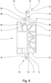
- Fig. 1
- eine erfindungsgemäße Baueinheit, bestehend aus einem Reihenklemmenblock und zwei Befestigungsklemmen, schräg von der Anschlussseite,
- Fig. 2
- eine erfindungsgemäße Befestigungsklemme, schräg von der Seite,
- Fig. 3
- ein vergrößerter Ausschnitt der oberen, zweiten Seite der Befestigungsklemme gemäß
Fig. 2 , - Fig. 4
- die Befestigungsklemme gemäß
Fig. 2 , schräg von unten, - Fig. 5
- ein vergrößerter Ausschnitt der unteren, ersten Seite der Befestigungsklemme gemäß
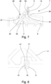
Fig. 4 , - Fig. 6
- die Befestigungsklemme gemäß
Fig. 2 in Seitenansicht, mit zwei Metallelementen, - Fig. 7
- eine vergrößerte Darstellung der oberen, zweiten Seite der Befestigungsklemme, im in die Wandöffnung eingesetzten Zustand, und
- Fig. 8
- eine vergrößerte Darstellung der unteren, ersten Seite der Befestigungsklemme, im in die Wandöffnung eingesetzten Zustand.
- 1
- a unit according to the invention, consisting of a terminal block and two fastening clamps, diagonally from the connection side,
- 2
- a fastening clamp according to the invention, diagonally from the side,
- 3
- according to an enlarged section of the upper, second side of the
fastening clamp 2 , - 4
- the mounting clamp according to
2 , diagonally from below, - figure 5
- according to an enlarged section of the lower, first side of the
fastening clamp 4 , - 6
- the mounting clamp according to
2 in side view, with two metal elements, - Figure 7
- an enlarged view of the upper, second side of the fastening clamp, when inserted into the wall opening, and
- 8
- an enlarged view of the lower, first side of the mounting clamp, in the state used in the wall opening.
Die Figuren zeigen eine bevorzugte Ausführungsform einer erfindungsgemä-ßen Befestigungsklemme 1 mit einem Klemmengehäuse 2, das eine erste, untere Gehäuseseite 21 und eine zweite, obere Gehäuseseite 22 aufweist. Die Befestigungsklemme 1 dient zur Fixierung mindestens einer Reihenklemme 31 in einer Wandöffnung 4 einer Gehäusewand 5, wobei es sich bei der Gehäusewand 5 beispielsweise um eine Schaltschrankwand handeln kann.The figures show a preferred embodiment of a
In
Die
Die Metallelemente 11 sind derart ausgebildet und angeordnet, dass im montierten Zustand der Befestigungsklemme 1 zwischen dem scharfkantigen Abschnitt 12 und einem Abschnitt 52 der Gehäusewand 5, der an die obere Innenkante 42 der Wandöffnung 4 angrenzt, eine kraftschlüssige Verbindung besteht. Aus der Darstellung gemäß
Zusätzlich zum scharfkantigen Abschnitt 12 ist an dem Metallelement 11 noch ein abgerundeter Abschnitt 13 ausgebildet, der ebenfalls in die Ausnehmung 10 im Rastarm 7 hineinragt. Der abgerundete Abschnitt 13 ist derart angeordnet, dass sich die Befestigungsklemme 1 im montierten Zustand über den abgerundeten Abschnitt 13 an der oberen Innenkante 42 der Wandöffnung 4 abstützt. Die obere Innenkante 42 der Wandöffnung 4 ist somit im montierten Zustand der Befestigungsklemme 1 von der Ausnehmung 10 im Rastarm 7 derart aufgenommen, dass zwischen dem abgerundeten Abschnitt 13 und dem scharfkantigen Abschnitt 12 des Metallelements 11 einerseits und der Gehäusewand 5 andererseits eine kraftschlüssige Verbindung besteht, die ein seitliches Verrutschen der Befestigungsklemme 1 verhindert.In addition to the sharp-edged
Aus der vergrößerten Darstellung des oberen Teils der Befestigungsklemme 1 gemäß
Aus der Darstellung der Befestigungsklemme 1 gemäß den
Aus der vergrößerten Darstellung des unteren Teils der Befestigungsklemme 1 gemäß
In
Aus den
Insbesondere aus den
Damit die Auslenkung des Rastarms 7 in Richtung der zweiten Gehäuseseite 22 beim Einschwenken der Befestigungsklemme 1 in die Wandöffnung 4 nicht durch den Stützarm 24 blockiert wird, weist das freie Ende 9 des Rastarms 7 auf der dem Stützarm 24 zugewandten Seite eine Schräge 26 auf. Außerdem ist das freie Ende des Stützarms 24 vom freien Ende 9 des Rastarms 7 weggebogen, so dass der Stützarm 24 einen Auflagebereich 27 aufweist, der beim Einsetzen der Befestigungsklemme 1 in die Wandöffnung 4 mit der Schräge 26 am Rastarm 7 zusammenwirkt. Beim Einschwenken der Befestigungsklemme 1 in die Wandöffnung 4 gleitet der Rastarm 7 mit seiner Schräge 26 an der Auflagefläche 27 des Stützarms 24 entlang, wobei gleichzeitig der Stützarm 24 etwas in Richtung der zweiten Gehäuseseite 22 gedrückt wird. Aus einem Vergleich der
Um das Einschwenken der Befestigungsklemme 1 in die Wandöffnung zu erleichtem, weist der Rastarm 7 eine Einführschräge 28 auf, die auf der der zweiten Gehäuseseite 22 des Klemmengehäuses 2 abgewandten Seite des Rastarms 7 zwischen dessen Fußbereich 8 und der Ausnehmung 10 angeordnet ist. Diese Einführschräge 28 am Rastarm 7 ist besonders aus den
Claims (14)
- Fastening clip (1) for fixing at least one terminal block (31) in a wall opening (4) of a housing wall (5), with a terminal housing (2) and with at least one clamping element,wherein the terminal housing (2) has two opposing housing sides (21, 22) which, in the mounted state of the fastening clip (1), each interact with an inner edge (41, 42) of the wall opening (4), and wherein a recess (6) is formed in the first housing side (21), with which recess the terminal housing (2), in the mounted state of the fastening clip (1), is seated on the lower inner edge (41) of the wall opening (4)characterized inthat the clamping element is designed as a resilient locking arm (7) which is fastened by its base region (8) to the second housing side (22) of the terminal housing (2) and in which a recess (10) is formed which, in the mounted state of the fastening clip (1), receives the upper inner edge (42) of the wall opening (4), andthat at least one metal element (11) is arranged in the locking arm (7), wherein the metal element (11) has a sharp-edged section (12) which projects into the recess (10) in such a way that, in the mounted state of the fastening clip (1), there is a non-positive connection between the sharp-edged section (12) and a section (52) of the housing wall (5) which is adjacent to the upper inner edge (42) of the wall opening (4).
- Fastening clip (1) according to claim 1, characterized in that the metal element (11) has a rounded section (13) which projects into the recess (10) in such a way that, in the mounted state of the fastening clip (1), the rounded section (13) is supported on the upper inner edge (42) of the wall opening (4).
- Fastening clip (1) according to claim 1 or 2, characterized in that at least one receiving pocket (14) is formed in the locking arm (7), in which the at least one metal element (11) is arranged and held in such a way that only the sharp-edged section (12) or the sharp-edged section (12) and the rounded section (13) protrude from the receiving pocket (14).
- Fastening clip (1) according to any one of claims 1 to 3, characterized in that at least one metal element (15) is arranged in the first housing side (21) of the terminal housing (2), wherein the metal element (15) has a sharp-edged section (16) which projects into the recess (6) in the first housing side (21) in such a way that, in the mounted state of the fastening clip (1), there is a non-positive connection between the sharp-edged section (16) and a section (51) of the housing wall (5) which adjoins the lower inner edge (41) of the wall opening (4).
- Fastening clip (1) according to claim 4, characterized in that the metal element (15) has a rounded section (17) which projects into the recess (6) in the first housing side (21) in such a way that, in the mounted state of the fastening clip (1), the rounded section (17) is supported on the lower inner edge (41) of the wall opening (4).
- Fastening clip (1) according to claim 4 or 5, characterized in that at least one receiving pocket (18) is designed in the first housing side (21) of the terminal housing (2), in which receiving pocket (18) the at least one metal element (15) is arranged and held in such a way that only the sharp-edged section (16) or the sharp-edged section (16) and the rounded section (17) protrude from the receiving pocket.
- Fastening clip (1) according to any one of claims 1 to 6, characterized in that the recess (6) in the first housing side (21) of the terminal housing (2) has a slope (23) over which the terminal housing (2) slides during insertion into the wall opening (4) until the terminal housing (2) rests with the recess (6) on the lower inner edge (41) of the wall opening (4).
- Fastening clip (1) according to any one of claims 1 to 7, characterized in that a tongue-like support arm (24) is arranged on the second housing side (22) of the terminal housing (2), which extends from the second housing side (22) of the terminal housing (2) in the direction of the free end (9) of the resilient locking arm (7) in such a way that the supporting arm (24) is deflected against its spring force by the locking arm (7) when the fastening clip (1) is fixed in the wall opening (4).
- Fastening clip (1) according to claim 8, characterized in that the base region (25) of the supporting arm (24) is arranged at a distance from the base region (8) of the locking arm (7) on the second housing side (22) of the terminal housing (2) in such a way that in the mounted state of the fastening clip (1) the base region (8) of the locking arm (7) is located on one side of the housing wall (5) and the base region (25) of the supporting arm (24) is located on the other side of the housing wall (5), and that the supporting arm (24) extends away from the second housing side (22) of the terminal housing (2) at an angle α greater than 90°.
- Fastening clip (1) according to claim 9, characterized in that the free end (9) of the locking arm (7) has a slope (26) on the side facing the supporting arm (24), and the free end (25) of the supporting arm (24) is bent away from the free end (9) of the locking arm (7), so that the supporting arm (24) has a bearing region (27) which interacts with the slope (26) of the locking arm (7) when the fastening clip (1) is inserted into the wall opening (4).
- Fastening clip (1) according to any one of claims 1 to 10, characterized in that the locking arm (7) has an insertion slope (28) which is arranged on the side of the locking arm (7) facing away from the second housing side (22) of the terminal housing (2) between the base region (8) of the locking arm (7) and the recess (10).
- Fastening clip (1) according to any one of claims 1 to 10, characterized in that a receptacle (29) is designed in the free end (9) of the locking arm (7) which serves to receive a tool for releasing the fixing of the fastening clip (1) in the wall opening (4).
- Assembly comprising two fastening clips (1) according to any one of claims 1 to 12 and a terminal block (3) comprising a plurality of terminal blocks (31) arranged side by side, wherein the terminal blocks (31) are arranged between the fastening clips (1) and each have a terminal housing (32) with at least two conductor connection elements arranged therein.
- Assembly unit according to claim 13, characterized in that the fastening clips (1) are each mechanically connected to the adjacent terminal block (31) via latching elements formed on their terminal housings (2), in particular via latching pins and/or latching recesses, for which corresponding latching recesses and/or latching pins are designed in the clip housing (32) of the terminal blocks (31).
Applications Claiming Priority (1)
| Application Number | Priority Date | Filing Date | Title |
|---|---|---|---|
| DE102020105580.3A DE102020105580B4 (en) | 2020-03-03 | 2020-03-03 | Fastening clamp for fixing at least one terminal block in a wall opening |
Publications (2)
| Publication Number | Publication Date |
|---|---|
| EP3876362A1 EP3876362A1 (en) | 2021-09-08 |
| EP3876362B1 true EP3876362B1 (en) | 2023-04-05 |
Family
ID=74858184
Family Applications (1)
| Application Number | Title | Priority Date | Filing Date |
|---|---|---|---|
| EP21159457.7A Active EP3876362B1 (en) | 2020-03-03 | 2021-02-26 | Fastening clip |
Country Status (3)
| Country | Link |
|---|---|
| EP (1) | EP3876362B1 (en) |
| CN (1) | CN113334288B (en) |
| DE (1) | DE102020105580B4 (en) |
Family Cites Families (13)
| Publication number | Priority date | Publication date | Assignee | Title |
|---|---|---|---|---|
| DE29907005U1 (en) | 1999-04-20 | 1999-07-15 | Adels Kg | Connection and / or connection terminal for an electrical device |
| US6709286B1 (en) | 2002-10-03 | 2004-03-23 | Hon Hai Precision Ind. Co., Ltd. | Electrical connector |
| DE10315661B4 (en) | 2003-04-04 | 2005-11-10 | Phoenix Contact Gmbh & Co. Kg | Locking element for a wall feed-through terminal / connector with wedge-shaped attachment |
| GB0406706D0 (en) * | 2004-03-25 | 2004-04-28 | Delphi Tech Inc | Electrical connector |
| EP1655813A1 (en) * | 2004-11-09 | 2006-05-10 | Phoenix Contact GmbH & Co. KG | Attachment for electrical connector |
| DE102005062059B4 (en) | 2005-12-22 | 2008-11-27 | Phoenix Contact Gmbh & Co. Kg | Electrical connection terminals with a fastening device for passing a line through a housing wall |
| DE102010015449A1 (en) | 2009-11-05 | 2011-05-19 | Weidmüller Interface GmbH & Co. KG | Mounting arrangement for electrical appliances |
| DE102011110637B4 (en) * | 2011-08-18 | 2016-01-28 | Wago Verwaltungsgesellschaft Mbh | Connectors |
| DE102012011676B4 (en) | 2012-05-14 | 2022-02-03 | Phoenix Contact Gmbh & Co. Kg | Fastening clamp and assembly with two fastening clamps and several terminal blocks arranged side by side |
| JP6108236B2 (en) * | 2014-05-23 | 2017-04-05 | 住友電装株式会社 | connector |
| DE102016111847B4 (en) | 2016-06-28 | 2019-02-14 | Phoenix Contact Gmbh & Co. Kg | Through terminal |
| DE102017124143A1 (en) * | 2017-10-17 | 2019-04-18 | Phoenix Contact Gmbh & Co. Kg | mounting clamp |
| DE202018104285U1 (en) | 2018-07-25 | 2019-10-28 | Wago Verwaltungsgesellschaft Mbh | Conductor terminal |
-
2020
- 2020-03-03 DE DE102020105580.3A patent/DE102020105580B4/en active Active
-
2021
- 2021-02-26 EP EP21159457.7A patent/EP3876362B1/en active Active
- 2021-03-03 CN CN202110233060.8A patent/CN113334288B/en active Active
Also Published As
| Publication number | Publication date |
|---|---|
| EP3876362A1 (en) | 2021-09-08 |
| CN113334288B (en) | 2023-01-13 |
| CN113334288A (en) | 2021-09-03 |
| DE102020105580B4 (en) | 2022-03-24 |
| DE102020105580A1 (en) | 2021-09-09 |
Similar Documents
| Publication | Publication Date | Title |
|---|---|---|
| DE102011115637B4 (en) | Electrical connection terminal | |
| EP1657789B1 (en) | Connection device for direct connection of conductor ends, and electrical apparatus including such a connection device | |
| EP3111513A1 (en) | Connection terminal and spring-loaded terminal contact therefor | |
| DE10355195B4 (en) | wire connection | |
| DE102006049772B4 (en) | Service switching device | |
| EP1217692B1 (en) | Connecting terminal for electrical conductors | |
| DE102010060252B4 (en) | Electrical connection unit | |
| EP1818964B1 (en) | Fuse rail with lateral outlet contacts and lateral adapter module | |
| DE202012104617U1 (en) | Mounting a connection device | |
| DE202015102045U1 (en) | Spring-loaded clamping element with pivoting lever | |
| WO2007131631A1 (en) | Module with connectors for actuators and/or sensors | |
| DE102010045913A1 (en) | Wall bushing connector and fastener for this purpose | |
| DE102016111847B4 (en) | Through terminal | |
| DE102021104504A1 (en) | Terminal arrangement, connector terminal and electronic device | |
| EP3876362B1 (en) | Fastening clip | |
| LU93126B1 (en) | Through terminal | |
| DE102010033112B4 (en) | Electrical installation device | |
| WO2019076537A1 (en) | Fastening clamp | |
| DE102012202240A1 (en) | Clamping body for a connection terminal | |
| DE102004002850B4 (en) | Electrical connector | |
| EP0123040B1 (en) | Terminal board for electric and electronic apparatuses, e.g. overcurrent protection switches | |
| EP3625854A1 (en) | Connection device for connecting at least one electrical conductor to a stud terminal | |
| EP2009745B1 (en) | Electrical device with spring clip unit | |
| EP3931911A1 (en) | Connection device for electrical conductors, and spring element for a connection device | |
| DE102018103999B4 (en) | Power distribution box and assembly method of a fuse box into the power distribution box |
Legal Events
| Date | Code | Title | Description |
|---|---|---|---|
| PUAI | Public reference made under article 153(3) epc to a published international application that has entered the european phase |
Free format text: ORIGINAL CODE: 0009012 |
|
| STAA | Information on the status of an ep patent application or granted ep patent |
Free format text: STATUS: THE APPLICATION HAS BEEN PUBLISHED |
|
| AK | Designated contracting states |
Kind code of ref document: A1 Designated state(s): AL AT BE BG CH CY CZ DE DK EE ES FI FR GB GR HR HU IE IS IT LI LT LU LV MC MK MT NL NO PL PT RO RS SE SI SK SM TR |
|
| STAA | Information on the status of an ep patent application or granted ep patent |
Free format text: STATUS: REQUEST FOR EXAMINATION WAS MADE |
|
| 17P | Request for examination filed |
Effective date: 20220308 |
|
| RBV | Designated contracting states (corrected) |
Designated state(s): AL AT BE BG CH CY CZ DE DK EE ES FI FR GB GR HR HU IE IS IT LI LT LU LV MC MK MT NL NO PL PT RO RS SE SI SK SM TR |
|
| GRAP | Despatch of communication of intention to grant a patent |
Free format text: ORIGINAL CODE: EPIDOSNIGR1 |
|
| STAA | Information on the status of an ep patent application or granted ep patent |
Free format text: STATUS: GRANT OF PATENT IS INTENDED |
|
| INTG | Intention to grant announced |
Effective date: 20220909 |
|
| GRAS | Grant fee paid |
Free format text: ORIGINAL CODE: EPIDOSNIGR3 |
|
| GRAA | (expected) grant |
Free format text: ORIGINAL CODE: 0009210 |
|
| STAA | Information on the status of an ep patent application or granted ep patent |
Free format text: STATUS: THE PATENT HAS BEEN GRANTED |
|
| AK | Designated contracting states |
Kind code of ref document: B1 Designated state(s): AL AT BE BG CH CY CZ DE DK EE ES FI FR GB GR HR HU IE IS IT LI LT LU LV MC MK MT NL NO PL PT RO RS SE SI SK SM TR |
|
| REG | Reference to a national code |
Ref country code: GB Ref legal event code: FG4D Free format text: NOT ENGLISH |
|
| REG | Reference to a national code |
Ref country code: CH Ref legal event code: EP |
|
| REG | Reference to a national code |
Ref country code: AT Ref legal event code: REF Ref document number: 1558971 Country of ref document: AT Kind code of ref document: T Effective date: 20230415 |
|
| REG | Reference to a national code |
Ref country code: DE Ref legal event code: R096 Ref document number: 502021000540 Country of ref document: DE |
|
| REG | Reference to a national code |
Ref country code: IE Ref legal event code: FG4D Free format text: LANGUAGE OF EP DOCUMENT: GERMAN |
|
| P01 | Opt-out of the competence of the unified patent court (upc) registered |
Effective date: 20230424 |
|
| REG | Reference to a national code |
Ref country code: LT Ref legal event code: MG9D |
|
| REG | Reference to a national code |
Ref country code: NL Ref legal event code: MP Effective date: 20230405 |
|
| PG25 | Lapsed in a contracting state [announced via postgrant information from national office to epo] |
Ref country code: NL Free format text: LAPSE BECAUSE OF FAILURE TO SUBMIT A TRANSLATION OF THE DESCRIPTION OR TO PAY THE FEE WITHIN THE PRESCRIBED TIME-LIMIT Effective date: 20230405 |
|
| PG25 | Lapsed in a contracting state [announced via postgrant information from national office to epo] |
Ref country code: SE Free format text: LAPSE BECAUSE OF FAILURE TO SUBMIT A TRANSLATION OF THE DESCRIPTION OR TO PAY THE FEE WITHIN THE PRESCRIBED TIME-LIMIT Effective date: 20230405 Ref country code: PT Free format text: LAPSE BECAUSE OF FAILURE TO SUBMIT A TRANSLATION OF THE DESCRIPTION OR TO PAY THE FEE WITHIN THE PRESCRIBED TIME-LIMIT Effective date: 20230807 Ref country code: NO Free format text: LAPSE BECAUSE OF FAILURE TO SUBMIT A TRANSLATION OF THE DESCRIPTION OR TO PAY THE FEE WITHIN THE PRESCRIBED TIME-LIMIT Effective date: 20230705 Ref country code: ES Free format text: LAPSE BECAUSE OF FAILURE TO SUBMIT A TRANSLATION OF THE DESCRIPTION OR TO PAY THE FEE WITHIN THE PRESCRIBED TIME-LIMIT Effective date: 20230405 |
|
| PG25 | Lapsed in a contracting state [announced via postgrant information from national office to epo] |
Ref country code: RS Free format text: LAPSE BECAUSE OF FAILURE TO SUBMIT A TRANSLATION OF THE DESCRIPTION OR TO PAY THE FEE WITHIN THE PRESCRIBED TIME-LIMIT Effective date: 20230405 Ref country code: PL Free format text: LAPSE BECAUSE OF FAILURE TO SUBMIT A TRANSLATION OF THE DESCRIPTION OR TO PAY THE FEE WITHIN THE PRESCRIBED TIME-LIMIT Effective date: 20230405 Ref country code: LV Free format text: LAPSE BECAUSE OF FAILURE TO SUBMIT A TRANSLATION OF THE DESCRIPTION OR TO PAY THE FEE WITHIN THE PRESCRIBED TIME-LIMIT Effective date: 20230405 Ref country code: LT Free format text: LAPSE BECAUSE OF FAILURE TO SUBMIT A TRANSLATION OF THE DESCRIPTION OR TO PAY THE FEE WITHIN THE PRESCRIBED TIME-LIMIT Effective date: 20230405 Ref country code: IS Free format text: LAPSE BECAUSE OF FAILURE TO SUBMIT A TRANSLATION OF THE DESCRIPTION OR TO PAY THE FEE WITHIN THE PRESCRIBED TIME-LIMIT Effective date: 20230805 Ref country code: HR Free format text: LAPSE BECAUSE OF FAILURE TO SUBMIT A TRANSLATION OF THE DESCRIPTION OR TO PAY THE FEE WITHIN THE PRESCRIBED TIME-LIMIT Effective date: 20230405 Ref country code: GR Free format text: LAPSE BECAUSE OF FAILURE TO SUBMIT A TRANSLATION OF THE DESCRIPTION OR TO PAY THE FEE WITHIN THE PRESCRIBED TIME-LIMIT Effective date: 20230706 Ref country code: AL Free format text: LAPSE BECAUSE OF FAILURE TO SUBMIT A TRANSLATION OF THE DESCRIPTION OR TO PAY THE FEE WITHIN THE PRESCRIBED TIME-LIMIT Effective date: 20230405 |
|
| PG25 | Lapsed in a contracting state [announced via postgrant information from national office to epo] |
Ref country code: FI Free format text: LAPSE BECAUSE OF FAILURE TO SUBMIT A TRANSLATION OF THE DESCRIPTION OR TO PAY THE FEE WITHIN THE PRESCRIBED TIME-LIMIT Effective date: 20230405 |
|
| REG | Reference to a national code |
Ref country code: DE Ref legal event code: R097 Ref document number: 502021000540 Country of ref document: DE |
|
| PG25 | Lapsed in a contracting state [announced via postgrant information from national office to epo] |
Ref country code: SK Free format text: LAPSE BECAUSE OF FAILURE TO SUBMIT A TRANSLATION OF THE DESCRIPTION OR TO PAY THE FEE WITHIN THE PRESCRIBED TIME-LIMIT Effective date: 20230405 |
|
| PG25 | Lapsed in a contracting state [announced via postgrant information from national office to epo] |
Ref country code: SM Free format text: LAPSE BECAUSE OF FAILURE TO SUBMIT A TRANSLATION OF THE DESCRIPTION OR TO PAY THE FEE WITHIN THE PRESCRIBED TIME-LIMIT Effective date: 20230405 Ref country code: SK Free format text: LAPSE BECAUSE OF FAILURE TO SUBMIT A TRANSLATION OF THE DESCRIPTION OR TO PAY THE FEE WITHIN THE PRESCRIBED TIME-LIMIT Effective date: 20230405 Ref country code: RO Free format text: LAPSE BECAUSE OF FAILURE TO SUBMIT A TRANSLATION OF THE DESCRIPTION OR TO PAY THE FEE WITHIN THE PRESCRIBED TIME-LIMIT Effective date: 20230405 Ref country code: EE Free format text: LAPSE BECAUSE OF FAILURE TO SUBMIT A TRANSLATION OF THE DESCRIPTION OR TO PAY THE FEE WITHIN THE PRESCRIBED TIME-LIMIT Effective date: 20230405 Ref country code: DK Free format text: LAPSE BECAUSE OF FAILURE TO SUBMIT A TRANSLATION OF THE DESCRIPTION OR TO PAY THE FEE WITHIN THE PRESCRIBED TIME-LIMIT Effective date: 20230405 Ref country code: CZ Free format text: LAPSE BECAUSE OF FAILURE TO SUBMIT A TRANSLATION OF THE DESCRIPTION OR TO PAY THE FEE WITHIN THE PRESCRIBED TIME-LIMIT Effective date: 20230405 |
|
| PLBE | No opposition filed within time limit |
Free format text: ORIGINAL CODE: 0009261 |
|
| STAA | Information on the status of an ep patent application or granted ep patent |
Free format text: STATUS: NO OPPOSITION FILED WITHIN TIME LIMIT |
|
| 26N | No opposition filed |
Effective date: 20240108 |