EP3473380A1 - Oszillationsantrieb mit verstellbarem oszillationswinkel - Google Patents
Oszillationsantrieb mit verstellbarem oszillationswinkel Download PDFInfo
- Publication number
- EP3473380A1 EP3473380A1 EP18184356.6A EP18184356A EP3473380A1 EP 3473380 A1 EP3473380 A1 EP 3473380A1 EP 18184356 A EP18184356 A EP 18184356A EP 3473380 A1 EP3473380 A1 EP 3473380A1
- Authority
- EP
- European Patent Office
- Prior art keywords
- eccentric
- additional
- drive according
- sleeve
- drive
- Prior art date
- Legal status (The legal status is an assumption and is not a legal conclusion. Google has not performed a legal analysis and makes no representation as to the accuracy of the status listed.)
- Granted
Links
Images




Classifications
-
- F—MECHANICAL ENGINEERING; LIGHTING; HEATING; WEAPONS; BLASTING
- F16—ENGINEERING ELEMENTS AND UNITS; GENERAL MEASURES FOR PRODUCING AND MAINTAINING EFFECTIVE FUNCTIONING OF MACHINES OR INSTALLATIONS; THERMAL INSULATION IN GENERAL
- F16H—GEARING
- F16H25/00—Gearings comprising primarily only cams, cam-followers and screw-and-nut mechanisms
- F16H25/16—Gearings comprising primarily only cams, cam-followers and screw-and-nut mechanisms for interconverting rotary motion and oscillating motion
-
- B—PERFORMING OPERATIONS; TRANSPORTING
- B23—MACHINE TOOLS; METAL-WORKING NOT OTHERWISE PROVIDED FOR
- B23D—PLANING; SLOTTING; SHEARING; BROACHING; SAWING; FILING; SCRAPING; LIKE OPERATIONS FOR WORKING METAL BY REMOVING MATERIAL, NOT OTHERWISE PROVIDED FOR
- B23D51/00—Sawing machines or sawing devices working with straight blades, characterised only by constructional features of particular parts; Carrying or attaching means for tools, covered by this subclass, which are connected to a carrier at both ends
- B23D51/16—Sawing machines or sawing devices working with straight blades, characterised only by constructional features of particular parts; Carrying or attaching means for tools, covered by this subclass, which are connected to a carrier at both ends of drives or feed mechanisms for straight tools, e.g. saw blades, or bows
- B23D51/161—Sawing machines or sawing devices working with straight blades, characterised only by constructional features of particular parts; Carrying or attaching means for tools, covered by this subclass, which are connected to a carrier at both ends of drives or feed mechanisms for straight tools, e.g. saw blades, or bows with dynamic balancing
-
- B—PERFORMING OPERATIONS; TRANSPORTING
- B24—GRINDING; POLISHING
- B24B—MACHINES, DEVICES, OR PROCESSES FOR GRINDING OR POLISHING; DRESSING OR CONDITIONING OF ABRADING SURFACES; FEEDING OF GRINDING, POLISHING, OR LAPPING AGENTS
- B24B27/00—Other grinding machines or devices
- B24B27/06—Grinders for cutting-off
- B24B27/08—Grinders for cutting-off being portable
-
- B—PERFORMING OPERATIONS; TRANSPORTING
- B25—HAND TOOLS; PORTABLE POWER-DRIVEN TOOLS; MANIPULATORS
- B25F—COMBINATION OR MULTI-PURPOSE TOOLS NOT OTHERWISE PROVIDED FOR; DETAILS OR COMPONENTS OF PORTABLE POWER-DRIVEN TOOLS NOT PARTICULARLY RELATED TO THE OPERATIONS PERFORMED AND NOT OTHERWISE PROVIDED FOR
- B25F3/00—Associations of tools for different working operations with one portable power-drive means; Adapters therefor
-
- B—PERFORMING OPERATIONS; TRANSPORTING
- B27—WORKING OR PRESERVING WOOD OR SIMILAR MATERIAL; NAILING OR STAPLING MACHINES IN GENERAL
- B27B—SAWS FOR WOOD OR SIMILAR MATERIAL; COMPONENTS OR ACCESSORIES THEREFOR
- B27B19/00—Other reciprocating saws with power drive; Fret-saws
- B27B19/006—Other reciprocating saws with power drive; Fret-saws with oscillating saw blades; Hand saws with oscillating saw blades
-
- H—ELECTRICITY
- H02—GENERATION; CONVERSION OR DISTRIBUTION OF ELECTRIC POWER
- H02K—DYNAMO-ELECTRIC MACHINES
- H02K7/00—Arrangements for handling mechanical energy structurally associated with dynamo-electric machines, e.g. structural association with mechanical driving motors or auxiliary dynamo-electric machines
- H02K7/003—Couplings; Details of shafts
-
- H—ELECTRICITY
- H02—GENERATION; CONVERSION OR DISTRIBUTION OF ELECTRIC POWER
- H02K—DYNAMO-ELECTRIC MACHINES
- H02K7/00—Arrangements for handling mechanical energy structurally associated with dynamo-electric machines, e.g. structural association with mechanical driving motors or auxiliary dynamo-electric machines
- H02K7/06—Means for converting reciprocating motion into rotary motion or vice versa
- H02K7/075—Means for converting reciprocating motion into rotary motion or vice versa using crankshafts or eccentrics
-
- B—PERFORMING OPERATIONS; TRANSPORTING
- B23—MACHINE TOOLS; METAL-WORKING NOT OTHERWISE PROVIDED FOR
- B23D—PLANING; SLOTTING; SHEARING; BROACHING; SAWING; FILING; SCRAPING; LIKE OPERATIONS FOR WORKING METAL BY REMOVING MATERIAL, NOT OTHERWISE PROVIDED FOR
- B23D61/00—Tools for sawing machines or sawing devices; Clamping devices for these tools
- B23D61/006—Oscillating saw blades
-
- B—PERFORMING OPERATIONS; TRANSPORTING
- B24—GRINDING; POLISHING
- B24B—MACHINES, DEVICES, OR PROCESSES FOR GRINDING OR POLISHING; DRESSING OR CONDITIONING OF ABRADING SURFACES; FEEDING OF GRINDING, POLISHING, OR LAPPING AGENTS
- B24B23/00—Portable grinding machines, e.g. hand-guided; Accessories therefor
- B24B23/04—Portable grinding machines, e.g. hand-guided; Accessories therefor with oscillating grinding tools; Accessories therefor
-
- B—PERFORMING OPERATIONS; TRANSPORTING
- B24—GRINDING; POLISHING
- B24B—MACHINES, DEVICES, OR PROCESSES FOR GRINDING OR POLISHING; DRESSING OR CONDITIONING OF ABRADING SURFACES; FEEDING OF GRINDING, POLISHING, OR LAPPING AGENTS
- B24B47/00—Drives or gearings; Equipment therefor
- B24B47/10—Drives or gearings; Equipment therefor for rotating or reciprocating working-spindles carrying grinding wheels or workpieces
- B24B47/16—Drives or gearings; Equipment therefor for rotating or reciprocating working-spindles carrying grinding wheels or workpieces performing a reciprocating movement, e.g. during which the sense of rotation of the working-spindle is reversed
-
- B—PERFORMING OPERATIONS; TRANSPORTING
- B24—GRINDING; POLISHING
- B24B—MACHINES, DEVICES, OR PROCESSES FOR GRINDING OR POLISHING; DRESSING OR CONDITIONING OF ABRADING SURFACES; FEEDING OF GRINDING, POLISHING, OR LAPPING AGENTS
- B24B49/00—Measuring or gauging equipment for controlling the feed movement of the grinding tool or work; Arrangements of indicating or measuring equipment, e.g. for indicating the start of the grinding operation
Definitions
- the invention relates to an oscillatory drive with a drive and with an eccentric coupling drive for converting a rotational movement of the drive in a rotational oscillating movement of a tool spindle about its longitudinal axis, said eccentric coupling drive having a driven by the drive eccentric having a first eccentricity, which cooperates with a coupling element with the tool spindle is coupled to implement the movement of the eccentric in a rotational oscillating movement of the tool spindle.
- Such an oscillation drive is for example from the DE 102 20 325 known.
- an eccentric pin is added at the end of a motor shaft.
- an eccentric bearing is held in the form of a needle bearing, which is held by a spherical outer ring between the two fork ends of a tuning fork.
- the tuning fork is rotatably connected at its other end to the tool spindle.
- oscillatory drives are highly flexible and suitable for many possible applications, applications and tools to be used.
- Their compact and lightweight design allows the user to adopt a wide variety of grip or working positions with respect to the hand tool or workpiece.
- the oscillation angle produced by a particular oscillatory drive is always associated with some compromise.
- oscillating tools that are used for surface grinding and thus have a relatively large triangular or circular paddle should advantageously be driven with a relatively small oscillation angle to avoid overloading the drive
- there are other tools that are advantageous with a larger oscillation angle should be driven, for example, to allow a quick work progress. This is especially in smaller tools in question, which do not have much inertia.
- an object of the invention to provide an oscillation drive which can detect a change in the maximum oscillation angle, i. the amplitude between two dead centers.
- the object of the invention is achieved in this way.
- the drive is reversible in its direction of rotation, in order to switch between a first relative position of eccentric and adjuzzenter, in which additively overlap the two eccentricities, and a second relative position, in which the eccentricities of eccentric and adjzxzenter subtractively superimposed to effect.
- a preferred embodiment is, for example, a combination of an amplitude of 2.6 ° with subtractive superimposition and an amplitude of 5.0 ° with additive superimposition.
- any other amplitude pairings within certain limits are also conceivable.
- Small amplitudes are advantageous for accurate work, as well as for cutting knives or very long or large tools.
- Large amplitude ensure a great work progress and lead to an inaccurate work.
- the eccentric and the formezzzenter between the first and second relative position are rotated by 180 ° to each other.
- the coupling element is designed as a swing fork, which is connected at a first end fixed to the tool spindle and is driven at a second end ofificatzxzenter.
- the additional eccentric is rotatably received on the eccentric and the second end of the tuning fork encloses an eccentric bearing, which is held on the Rajzzenter, from the outside.
- the eccentric bearing is designed as a pivot bearing with a spherical outer ring which is enclosed by two fork ends of the tuning fork.
- the eccentric preferably has an eccentric neck, which engages in an eccentrically arranged recess of the additional eccentric, on the outer surface of the eccentric bearing is held.
- the eccentric neck is formed at one end of a rotationally driven output.
- the drive in this case preferably has an electric motor, on the motor shaft of the eccentric neck is formed.
- a sleeve is rotatably mounted on the motor shaft, which is coupled via a driver in at least two relative positions with the additional eccentric.
- the additional eccentric on a disc which is rotatably disposed within the sleeve and abuts in the at least two relative positions on a nose of the sleeve.
- the disc has a resilient portion which expands under centrifugal force to the outside and rests against an inner surface of the sleeve for fixing the relative position between the eccentric and foizzzenter.
- the embodiment described above allows a particularly simple switching between the two amplitudes of the oscillation by reversing the direction of rotation of the motor shaft.
- the additional eccentric first stops when the direction of rotation of the motor shaft is reversed and is then taken along by the further rotation of the motor shaft as soon as the disc of the additional eccentric strikes against the nose of the sleeve. Stopping the relievezzenters is purely by inertia.
- Stopping the unbezzenters by inertia when switching the direction of rotation may result in unfavorable cases, such as by different fat fills, possibly to undefined states. It may thus result in unfavorable circumstances, a change in the amplitude of the oscillation angle, which deviates from the desired change.
- the additional eccentric can additionally be stopped by means of a braking device, before a takeover takes place again when switching the direction of rotation.
- a braking device which allows a braking ofificatzxzenters at a standstill relative to the housing and which dissolves with a rotating motor shaft under centrifugal force to cancel the braking effect.
- the sleeve has a guide slot in the form of a recess, through which engages a driving pin in an associated driver receiving the sanszzzenter to set the relative position between the eccentric and sanszzzenter.
- the braking device has two spring-loaded, radially movable brake shoes for braking the unbezzenters when reversing direction on the housing, which expand under centrifugal force outward against the spring action to cancel the braking.
- a bearing bush is held on the housing, on which the brake shoes rest upon rotation reversal, and wherein the brake shoes create under centrifugal force on an inner surface of the sleeve so as to fix the relative position between the eccentric and foizzzenter.
- the brake shoes are coupled via the driving pin, which extends through the guide slot of the sleeve into the driver receiving, with the Rajzxzenter.
- the invention further provides a system having an oscillatory drive of the type described above, comprising a plurality of tools, the tools having an encoding, and a controller for automatically adjusting the oscillation angle.
- an automatic adjustment of the oscillation angle can be determined depending on the tool used. This ensures that the relevant tool is always operated with the desired amplitude of the oscillation angle, so as to ensure an optimized use.
- the controller may be further configured to automatically adjust the oscillation angle and / or the speed.
- the tools concerned can be automatically operated with the optimum oscillation angle and the associated optimum speed.
- the coding is in this case preferably designed as an RFID chip.
- the drive preferably has an electronically commutated electric motor.
- the switching of the direction of rotation can be done automatically by the controller.
- the speed can be adjusted automatically.
- FIG. 1 an oscillation drive according to the invention is shown in perspective and designated overall by the numeral 10.
- the oscillatory drive 10 has a housing 12 which can be gripped around with one hand and at the rear end of which a receptacle 14 for a rechargeable battery is provided. From a front end of the housing 12, a tool spindle 20 protrudes downward at right angles. Various tools can be fastened to the tool spindle 20 by means of a quick-action clamping device, for which purpose a clamping lever 18 is provided which can be seen on the upper side of the housing 12.
- an on-off switch 16 is further recognizable, the for switching the machine on and off. Further, a reversing switch is provided, which is arranged on the right side of the housing 12 (not shown).
- Fig. 2 shows a longitudinal section through the oscillating drive 10 according to Fig. 1 ,
- the oscillation drive 10 has a drive 26, which in the present case is designed as an electronically commutated electric motor (EC motor).
- EC motor electronically commutated electric motor
- This has a motor shaft 27 which is rotatably supported by means of two bearings 30, 32.
- the rotational movement of the motor shaft 27 is converted via an eccentric coupling drive in a rotational oscillating movement of the tool spindle 20 about its longitudinal axis 21, as indicated by the double arrow 22.
- a further eccentric is additionally provided the amplitude of the oscillatory motion is variable.
- a 1925zxzenter 36 is provided which is held with a recess 37 directly on the Exzenterstutzen 35.
- the recess 37 is arranged eccentrically, so that an eccentric movement results on the outer surface of the additional eccentric 36, which results from the superimposition of the two eccentricities of the eccentric 34 and of the additional eccentric 36.
- an eccentric bearing 38 is held with a spherical outer ring of a swing fork 40 is gripped on both sides, the other end is firmly connected to the tool spindle 20. The eccentric movement of the eccentric bearing 38 is thus converted into an oscillating movement of the tool spindle 20.
- eccentricity the eccentric bearing 38 and thus the rocker arm 40 depends on the relative position between the eccentric 34 and the additional eccentric 36.
- the eccentricities of eccentric 34 and additional eccentric 36 add up, so that there is a maximum amplitude of the oscillatory motion.
- the additional eccentric 34 would be 180 ° in relation to the position in FIG Fig. 2 twisted, so a subtractive superposition of the two eccentricities would result, so that would result in a minimal deflection and thus a minimum amplitude of the oscillatory motion by the eccentric movement.
- Stopping the auxiliary eccentric 36 can easily be done by inertia or forced by a braking device.
- the Fig. 2 to 7 show the embodiment with a braking device, while the 8 to 11 show an embodiment without such a braking device, in which the stopping of the attorneyzentrzers when reversing the direction is done only by inertia.
- Fig. 3 are the essential moving parts of the execution with braking device in an exploded view one behind the other in the installed position.
- the rocker arm 40 At the left end of the rocker arm 40 is shown, which surrounds the eccentric bearing 38 at its spherical outer ring 39 with two fork ends 42, 43.
- the rocker arm 40 is rotatably fixed with a recess 41 on the tool spindle 20, for example by shrinking.
- the additional eccentric 36 is sleeve-shaped and has an eccentric recess 37, with which the additional eccentric 36 is rotatably supported on the eccentric pin 35.
- a washer 44 is integrally formed on the auxiliary eccentric 36, in which a driver receptacle 46 in the form of a radially extending groove 46 is provided.
- a sleeve 48 Adjoining the disk 44 of the additional eccentric 37 is a sleeve 48, in which a guide slot 50 in the form of a groove is provided, which extends over an angular range of 180 °.
- a total of 54 braking device 54 On the rear side of the sleeve 50 is designated a total of 54 braking device 54 which has two radially movable brake shoes 55, 56, which are acted upon by means of an externally enclosing spring ring 58 inwardly resiliently.
- One of the brake shoes 56, 57 in the illustration according to Fig. 3 the lower brake shoe 57, via a driver pin 52 which extends through the guide slot 50 therethrough with the Auxiliary eccentric 36 is coupled, since the driving pin 52 engages in the cam receiver 46 of the disc 44.
- the bearing bush 60 has a projecting towards the tool spindle 20 projection 61 on which the brake shoes 55, 56 can rest with its inner surface when they are pressed by the spring ring 58.
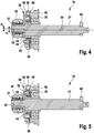
- Fig. 4 are the two eccentricities, which result from the eccentric 34 and the eccentric pin 35 and by the additional eccentric 36, indicated by e1 and e2. While the eccentric pin 35 has a larger eccentricity e1, the eccentricity e2 caused by the additional cam 36 is smaller than the first eccentricity e1.
- the amplitude of the oscillation angle can be adapted within relatively wide limits. For example, a combination of 2.6 ° / 5.0 ° (amplitude of oscillation angle from dead center to dead center) may be used.
- the brake shoes 55, 56 move outwards until they come to rest against an inner surface of the sleeve 48, so that on the one hand the braking is released and on the other hand the relative position between the eccentric 34 and the auxiliary eccentric 36 is fixed.
- the 8 to 11 show a simplified embodiment of the oscillating drive without braking device, which is generally designated 10a.
- Correspondingly modified parts are identified by corresponding reference numerals followed by the letter "a”, while the remaining corresponding parts are denoted by corresponding reference numerals (in FIG 10 and 11 is additionally the rotor body 66 of the engine recognizable).
- the sleeve-shaped additional eccentric 36a has a disk 44a (cf. Fig. 8, 9 . 11 ), one half of which is formed as a resilient portion 70.
- the disc 44a is movable within the enclosing sleeve 48a and has at the resilient portion 70 two ends 71, 72 which, depending on the direction of rotation, can abut either on one side or on the other side of a protruding nose 68 of the sleeve 48a.
- the additional eccentric 36a and thus the disc 44a is rotated in a clockwise or counterclockwise direction, so puts one end 71 or the other end 72 of the resilient portion 70 on the nose 68, so that there is a driving.
- the resilient portion 70 expands outwardly and abuts against the associated inner surface of the sleeve 48a, so that the relative position between the eccentric 34 and unbezzzenter 36a and thus the amplitude of the oscillatory motion is fixed.
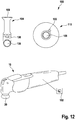
- Fig. 12 2 shows by way of example a system 100 with an oscillatory drive 10 of the type described above and with two exemplary tools 104 and 110.
- the tool 104 is an elongated sawing tool with a cutting edge 109 at the outer end.
- a fastening opening 108 is provided with which a positive reception on the tool spindle 20 is made possible.
- an RFID chip is provided, which is indicated schematically at 106.
- the oscillation drive 10 has an only schematically indicated with 102 control electronics, which reads the RFID chip 106 automatically and then automatically adjusts an associated amplitude of the oscillation angle.
- the EC motor of the oscillation drive 10 is automatically operated by the control device 102 with the associated direction of rotation, which results in the desired oscillation angle.
- the second tool 110 shown by way of example is a grinding tool with a relatively large sanding pad, which in turn is provided with an RFID chip 106. Due to the relatively large inertia of the grinding tool this should usually be operated with a lower amplitude of the oscillation angle. This adjustment to the lower amplitude is in turn automatically effected via the control device 102.
Landscapes
- Engineering & Computer Science (AREA)
- Mechanical Engineering (AREA)
- Power Engineering (AREA)
- Life Sciences & Earth Sciences (AREA)
- General Engineering & Computer Science (AREA)
- Wood Science & Technology (AREA)
- Forests & Forestry (AREA)
- Finish Polishing, Edge Sharpening, And Grinding By Specific Grinding Devices (AREA)
- Apparatuses For Generation Of Mechanical Vibrations (AREA)
Abstract
Description
- Die Erfindung betrifft einen Oszillationsantrieb mit einem Antrieb und mit einem Exzenterkoppeltrieb zur Umsetzung einer Drehbewegung des Antriebs in eine drehoszillierende Bewegung einer Werkzeugspindel um ihre Längsachse, wobei der Exzenterkoppeltrieb einen vom Antrieb angetriebenen Exzenter mit einer ersten Exzentrizität aufweist, der mit einem Koppelelement zusammenwirkt, das mit der Werkzeugspindel gekoppelt ist, um die Bewegung des Exzenters in eine drehoszillierende Bewegung der Werkzeugspindel umzusetzen.
- Ein derartiger Oszillationsantrieb ist beispielsweise aus der
DE 102 20 325 bekannt. - Hierbei ist am Ende einer Motorwelle ein Exzenterzapfen aufgenommen. Auf dem Exzenterzapfen ist ein Exzenterlager in Form eines Nadellagers gehalten, das über einen balligen Außenring zwischen den beiden Gabelenden einer Schwinggabel gehalten ist. Die Schwinggabel ist an ihrem anderen Ende drehfest mit der Werkzeugspindel verbunden.
- Mit einer derartigen Ausführung ergibt sich ein ziemlich einfacher Aufbau des Oszillationsantriebs. Derartige Oszillationsantriebe finden vielfältige Verwendung, etwa beim Schleifen, Sägen oder auch beim Schneiden von Werkstücken. Hierbei liegen übliche Oszillationsfrequenzen etwa im Bereich von 5.000 bis 25.000 Oszillationen pro Minute. Typische maximale Verschwenkwinkel der Werkzeugspindel (auch als Amplitude der Oszillation bezeichnet) betragen etwa zwischen 0,5° und 7° (von Totpunkt zu Totpunkt).
- Solchermaßen gestaltete Oszillationsantriebe sind hochflexibel und für viele mögliche Anwendungen, Einsatzgebiete und zu verwendende Werkzeuge geeignet. Durch ihre kompakte und leichte Gestalt gestatten sie es dem Anwender, verschiedenste Griff- bzw. Arbeitspositionen in Bezug auf das Handwerkzeug bzw. das Werkstück einzunehmen.
- Wegen der Vielfältigkeit der verwendbaren Werkzeuge ist der Oszillationswinkel, der von einem bestimmten Oszillationsantrieb erzeugt wird, immer mit einem gewissen Kompromiss verbunden. Während zum Beispiel Oszillationswerkzeuge, die zum Flächenschleifen verwendet werden und somit einen relativ großen dreieckförmigem oder runden Schleifteller aufweisen, vorteilhafterweise mit einem relativ kleinen Oszillationswinkel angetrieben werden sollten, um eine Überlastung des Antriebs zu vermeiden, gibt es andere Werkzeuge, die vorteilhaft mit einem größeren Oszillationswinkel angetrieben werden sollten, etwa um einen schnellen Arbeitsfortschritt zu ermöglichen. Dies kommt insbesondere bei kleineren Werkzeugen in Frage, welche keine große Trägheit besitzen. Dagegen sind für andere Arbeiten, beispielsweise zum Durchtrennen des Klebewulstes von Autoscheiben beim Ausglasen geringe Oszillationswinkel bevorzugt, um eine Selbstzerstörung der betreffenden Schneidemesser zu vermeiden.
- Vor diesem Hintergrund liegt der Erfindung die Aufgabe zugrunde, einen Oszillationsantrieb bereitzustellen, der eine Veränderung des maximalen Oszillationswinkels, d.h. der Amplitude zwischen zwei Totpunkten, ermöglicht.
- Diese Aufgabe wird bei einem Oszillationsantrieb gemäß der eingangs genannten Art erfindungsgemäß dadurch gelöst, dass der Exzenter mit einem Zusatzexzenter mit einer zweiten Exzentrizität gekoppelt ist, so dass sich die Exzentrizitäten überlagern, wobei die Relativlage zwischen dem Exzenter und dem Zusatzexzenter in mindestens zwei unterschiedliche Positionen verstellbar ist.
- Die Aufgabe der Erfindung wird auf diese Weise gelöst.
- Da sich die Wirkungen von Exzenter und Zusatzexzenter überlagern, ergibt sich eine resultierende Bewegung, die zwischen Extremen variiert werden kann, nämlich zwischen einer additiven Überlagerung, bei welcher sich die beiden Exzentrizitäten addieren, und zwischen einer Stellung, in der sich eine minimale Amplitude ergibt, da sich die beiden Exzentrizitäten substraktiv überlagern.
- Grundsätzlich ist es denkbar, die Relativposition zwischen Exzenter und Zusatzexzenter kontinuierlich verstellbar auszugestalten. Auf diese Weise ergibt sich eine Amplitude der Oszillationsbewegung, die in vorgegebenen Grenzen stufenlos veränderbar ist.
- Gemäß einer bevorzugten Weiterbildung der Erfindung ist der Antrieb in seiner Drehrichtung umschaltbar ausgebildet, um eine Umschaltung zwischen einer ersten Relativposition von Exzenter und Zusatzexzenter, in welcher sich die beiden Exzentrizitäten additiv überlagern, und einer zweiten Relativposition, in welcher sich die Exzentrizitäten von Exzenter und Zusatzexzenter substraktiv überlagern, zu bewirken.
- Auf diese Weise ergibt sich eine besonders einfache Konstruktion. Durch einfache Umschaltung der Drehrichtung des Antriebs können zwei unterschiedliche Amplituden der Oszillationsbewegung eingestellt werden. Je nach Auslegung von Exzenter und Zusatzexzenter können auf diese Weise unterschiedliche Paarungen von Oszillationswinkeln erzielt werden.
- Eine bevorzugte Ausgestaltung ist beispielsweise eine Kombination einer Amplitude von 2,6° bei subtraktiver Überlagerung und einer Amplitude von 5,0° bei additiver Überlagerung. Es sind aber grundsätzlich auch beliebige andere Amplitudenpaarungen in gewissen Grenzen denkbar. Kleine Amplituden sind von Vorteil für ein genaues Arbeiten, sowie für Schneidmesser oder sehr lange bzw. große Werkzeuge. Große Amplitude dagegen sorgen für einen großen Arbeitsfortschritt und führen zu einem ungenaueren Arbeiten. Manche Werkzeuge und auch manche Oszillationsantriebe, die beim Arbeiten zu sehr großen Beschleunigungskräften führen, wie etwa sehr große Schleifplatten oder lange Messer, sind nur für kleinere Amplituden geeignet.
- Vorzugsweise sind der Exzenter und der Zusatzexzenter zwischen der ersten und zweiten Relativposition um 180° zueinander verdreht.
- Auf diese Weise kann einfach durch die Drehrichtungsumkehr die maximale Differenz zwischen der additiven Überlagerung der Exzentrizitäten und der substraktiven Überlagerung der Exzentrizitäten erreicht werden.
- Gemäß einer weiteren Ausgestaltung der Erfindung ist das Koppelelement als Schwing¬gabel ausgebildet, welche an einem ersten Ende fest mit der Werkzeugspindel verbunden ist und an einem zweiten Ende vom Zusatzexzenter angetrieben ist.
- Dies ermöglicht eine besonders einfache Konstruktion.
- Gemäß einer weiteren Ausgestaltung der Erfindung ist der Zusatzexzenter auf dem Exzenter drehbar aufgenommen und das zweite Ende der Schwinggabel umschließt ein Exzenterlager, das auf dem Zusatzexzenter gehalten ist, von außen.
- Vorzugsweise ist das Exzenterlager als Drehlager mit einem balligen Außenring ausgebildet, der von zwei Gabelenden der Schwinggabel umschlossen ist.
- Auf diese Weise ergibt sich eine besonders einfache, zuverlässige Konstruktion.
- Der Exzenter weist bevorzugt einen Exzenterstutzen auf, der in eine exzentrisch angeordnete Ausnehmung des Zusatzexzenters eingreift, auf dessen Außenoberfläche das Exzenterlager gehalten ist.
- Weiter bevorzugt ist der Exzenterstutzen an einem Ende eines rotatorisch angetriebenen Abtriebs ausgebildet.
- Der Antrieb weist hierbei vorzugsweise einen Elektromotor auf, an dessen Motorwelle der Exzenterstutzen ausgebildet ist.
- Durch diese Merkmale ist eine besonders einfache und zuverlässige Konstruktion gewährleistet.
- Gemäß einer weiteren Ausgestaltung der Erfindung ist auf der Motorwelle eine Hülse drehfest angeordnet, die über einen Mitnehmer in mindestens zwei Relativpositionen mit dem Zusatzexzenter koppelbar ist.
- Auf diese Weise kann die Relativposition zwischen Zusatzexzenter und Exzenter, der unmittelbar an der Motorwelle aufgenommen ist, sehr einfach verstellt werden.
- Gemäß einer weiteren Ausführung der Erfindung weist der Zusatzexzenter eine Scheibe auf, die innerhalb der Hülse verdrehbar angeordnet ist und in den mindestens zwei Relativpositionen an einer Nase der Hülse anschlägt.
- Auf diese Weise gestaltet sich die Umschaltung zwischen den beiden Relativpositionen durch Drehrichtungsumkehr der Motorwelle besonders einfach.
- Gemäß einer weiteren Ausgestaltung der Erfindung weist die Scheibe einen federnden Abschnitt auf, der sich unter Fliehkraftwirkung nach außen aufweitet und an einer Innenoberfläche der Hülse zur Fixierung der Relativlage zwischen Exzenter und Zusatzexzenter anliegt.
- Durch die Aufweitung des federnden Abschnitts unter Fliehkraftwirkung ist gewährleistet, dass sich die Relativlage zwischen Exzenter und Zusatzexzenter und somit die Amplitude der Oszillation im Betrieb nicht mehr verändern kann.
- Die zuvor beschriebene Ausführung erlaubt eine besonders einfache Umschaltung zwischen den beiden Amplituden der Oszillation durch Drehrichtungsumkehr der Motorwelle. Der Zusatzexzenter bleibt bei Drehrichtungsumkehr der Motorwelle zunächst stehen und wird dann durch die weitere Drehung der Motorwelle mitgenommen, sobald die Scheibe des Zusatzexzenters an der Nase der Hülse anschlägt. Das Stehenbleiben des Zusatzexzenters erfolgt rein durch Trägheit.
- Das Stehenbleiben des Zusatzexzenters durch Trägheit beim Umschalten der Drehrichtung kann in ungünstigen Fällen, etwa durch unterschiedliche Fettfüllungen, gegebenenfalls zu undefinierten Zuständen führen. Es kann sich so unter ungünstigen Umständen eine Veränderung der Amplitude des Oszillationswinkels ergeben, die von der gewünschten Veränderung abweicht.
- Um derartige Probleme zu vermeiden, kann zusätzlich der Zusatzexzenter mittels einer Bremseinrichtung angehalten werden, bevor bei der Umschaltung der Drehrichtung wieder eine Mitnahme erfolgt.
- Hierzu ist eine Bremseinrichtung vorgesehen, welche eine Bremsung des Zusatzexzenters im Stillstand relativ zum Gehäuse erlaubt und die sich bei rotierender Motorwelle unter Fliehkraftwirkung löst, um die Bremswirkung aufzuheben.
- Auf diese Weise ist in jedem Fall gewährleistet, dass der Zusatzexzenter zunächst stehen bleibt und erst, nachdem sich der Exzenter um 180° relativ dazu bewegt, hat, mitgenommen wird. Auf diese Weise ist eine Umschaltung der Relativposition zwischen Exzenter und Zusatzexzenter jeweils um die gewünschte Verdrehung von 180° zueinander in jedem Falle gewährleistet, so dass sich die Umschaltung zwischen der additiven Überlagerung der Exzentrizitäten und der subtraktiven Überlagerung der Exzentrizitäten präzise ergibt.
- Gemäß einer weiteren Ausgestaltung der Erfindung weist die Hülse eine Führungskulisse in Form einer Ausnehmung auf, durch welche hindurch ein Mitnehmerstift in eine zugeordnete Mitnehmeraufnahme am Zusatzexzenter eingreift, um die Relativposition zwischen Exzenter und Zusatzexzenter festzulegen.
- Auf diese Weise wird die Mitnahme zwischen Exzenter und Zusatzexzenter auf einfache Weise ermöglicht.
- In weiterer Ausgestaltung der Erfindung weist die Bremseinrichtung zwei federnd beaufschlagte, radial bewegliche Bremsbacken zur Bremsung des Zusatzexzenters bei Drehrichtungsumkehr am Gehäuse auf, welche sich unter Fliehkraftwirkung nach außen gegen die Federwirkung aufweiten, um die Bremsung aufzuheben.
- Auf diese Weise ist gewährleistet, dass der Zusatzexzenter bei Drehrichtungsumkehr zunächst abgebremst wird und dass die Bremsung bei zunehmender Drehzahl wieder aufgehoben wird.
- Bevorzugt ist hierbei am Gehäuse eine Lagerbuchse gehalten, auf der die Bremsbacken bei Drehrichtungsumkehr aufliegen, und wobei sich die Bremsbacken unter Fliehkraftwirkung an einer Innenoberfläche der Hülse anlegen, um so die Relativlage zwischen Exzenter und Zusatzexzenter zu fixieren.
- Auf diese Weise ist gewährleistet, dass die Bremsbacken im Betrieb die Relativlage zwischen Exzenter und Zusatzexzenter sicher fixieren, so dass sich die Amplitude des Oszillationswinkels nicht verändern kann.
- Gemäß einer weiteren Ausgestaltung der Erfindung sind die Bremsbacken über den Mitnehmerstift, der sich durch die Führungskulisse der Hülse hindurch in die Mitnehmeraufnahme erstreckt, mit dem Zusatzexzenter gekoppelt.
- Auf diese Weise wird einerseits die Mitnahme des Zusatzexzenters bewirkt und andererseits werden gleichzeitig die Bremsbacken mit dem Zusatzexzenter gekoppelt.
- Durch die Erfindung wird ferner ein System mit einem Oszillationsantrieb gemäß der vorstehend beschriebenen Art bereitgestellt, mit einer Mehrzahl von Werkzeugen, wobei die Werkzeuge eine Codierung aufweisen, und wobei eine Steuerung zur automatischen Einstellung des Oszillationswinkels vorgesehen ist.
- Auf diese Weise kann bei einer Verwendung des Oszillationsantriebs mit einer Mehrzahl von Werkzeugen eine automatische Einstellung des Oszillationswinkels in Abhängigkeit vom verwendeten Werkzeug festgelegt werden. Hierdurch wird erreicht, dass das betreffende Werkzeug immer mit der gewünschten Amplitude des Oszillationswinkels betrieben wird, um so einen optimierten Einsatz zu gewährleisten.
- Die Steuerung kann ferner zur automatischen Einstellung des Oszillationswinkels und/oder der Drehzahl ausgebildet sein.
- Somit können die betreffenden Werkzeuge automatisch mit dem optimalen Oszillationswinkel und der zugeordneten optimalen Drehzahl betrieben werden.
- Die Codierung ist hierbei bevorzugt als RFID-Chip ausgebildet.
- Der Antrieb weist vorzugsweise einen elektronisch kommutierten Elektromotor auf. Hierbei kann die Umschaltung der Drehrichtung automatisch durch die Steuerung erfolgen. Auch lässt sich die Drehzahl automatisch einstellen.
- Es versteht sich, dass die vorstehend genannten und die nachstehend noch zu erläuternden Merkmale der Erfindung nicht nur in der jeweils angegebenen Kombination, sondern auch in anderen Kombinationen oder in Alleinstellung verwendbar sind, ohne den Rahmen der vorliegenden Erfindung zu verlassen.
- Weitere Merkmale und Vorteile der Erfindung ergeben sich aus der nachfolgenden Beschreibung bevorzugter Ausführungsbeispiele unter Bezugnahme auf die Zeichnung. Es zeigen:
- Fig. 1
- eine perspektivische Darstellung eines erfindungsgemäßen Oszillationsantriebs;
- Fig. 2
- einen Längsschritt durch den Oszillationsantrieb gemäß
Fig. 1 ; - Fig. 3
- eine Explosionsansicht der wesentlichen Teile des Antriebsstrangs, die miteinander in Einbaurichtung entlang einer Längsachse dargestellt sind;
- Fig. 4
- einen Längsschritt durch die Motorwelle und zugeordnete Teile im Bereich der Lagerung mit Zusatzexzenter und Exzenterlager in einer ersten Relativposition zwischen Exzenter und Zusatzexzenter, in der sich die beiden Exzentrizitäten additiv überlagern;
- Fig. 5
- eine Darstellung gemäß
Fig. 4 , wobei jedoch Exzenter und Zusatzexzenter in eine um 180° zueinander verdrehte Position bewegt sind, in der sich die beiden Exzentrizitäten subtraktiv überlagern; - Fig. 6
- eine vergrößerte perspektivische Darstellung der Motorwelle im Bereich der Bremseinrichtung, wobei zum Zwecke der besseren Erkennbarkeit eine Reihe von Teilen freigeschnitten wurden;
- Fig. 7
- eine Darstellung gemäß
Fig. 6 , wobei jedoch ein durch die Mittelachse der Motorwelle verlaufender Längsschnitt vorgesehen wurde; - Fig. 8
- eine abgewandelte Ausführung des Oszillationsantriebs gemäß der
Fig. 4 und 5 mit einem Längsschnitt durch den vorderen Teil der Motorwelle, mit zugeordneter Lagerung, Exzenter, Zusatzexzenter und Exzenterlager in einer ersten Relativposition zwischen Exzenter und Zusatzexzenter, in der sich eine additive Überlagerung der beiden Exzentrizitäten ergibt; - Fig. 9
- eine Darstellung gemäß
Fig. 8 , wobei Exzenter und Zusatzexzenter jedoch um 180° zueinander verdreht wurden, so dass sich eine substraktive Überlagerung der beiden Exzentrizitäten ergibt; - Fig. 10
- eine vergrößerte perspektivische Darstellung der Ausführung gemäß der
Fig. 8 und 9 , wobei die Motorwelle nebst dem darauf angeordneten Rotorkörper, die Hülse zwischen Exzenter und Zusatzexzenter, sowie das Exzenterlager erkennbar sind; - Fig. 11
- eine Vorderansicht der Anordnung gemäß
Fig. 10 nach Abnahme des Exzenterlagers und - Fig. 12
- ein System mit einem Oszillationsantrieb gemäß
Fig. 1 und mit zwei zugehörigen Werkzeugen. - In
Fig. 1 ist ein erfindungsgemäßer Oszillationsantrieb perspektivisch dargestellt und insgesamt mit der Ziffer 10 bezeichnet. Der Oszillationsantrieb 10 weist ein Gehäuse 12 auf, das mit einer Hand umgreifbar ist und an dessen hinterem Ende eine Aufnahme 14 für einen Akkumulator vorgesehen ist. Aus einem vorderen Ende des Gehäuses 12 steht eine Werkzeugspindel 20 rechtwinklig nach unten hervor. An der Werkzeugspindel 20 können verschiedene Werkzeuge mittels einer Schnellspanneinrichtung befestigt werden, wozu ein Spannhebel 18 vorgesehen ist, der an der Oberseite des Gehäuses 12 erkennbar ist. An der Oberseite des Gehäuses 12 ist ferner ein Ein-Aus-Schalter 16 erkennbar, der zum Ein- und Ausschalten der Maschine dient. Ferner ist ein Schalter zur Drehrichtungsumkehr vorgesehen, der auf der rechten Seite des Gehäuses 12 angeordnet ist (nicht dargestellt). -
Fig. 2 zeigt einen Längsschnitt durch den Oszillationsantrieb 10 gemäßFig. 1 . - Der Oszillationsantrieb 10 weist einen Antrieb 26 auf, der im vorliegenden Fall als elektronisch kommutierbarer Elektromotor (EC-Motor) ausgebildet ist. Dieser weist eine Motorwelle 27 auf, die mittels zweier Lager 30, 32 drehbar gelagert ist. Die Drehbewegung der Motorwelle 27 wird über einen Exzenterkoppeltrieb in eine drehoszillierende Bewegung der Werkzeugspindel 20 um ihre Längsachse 21 umgesetzt, wie durch den Doppelpfeil 22 angedeutet ist. Während bei herkömmlichen Exzenterkoppeltrieben eine exzentrische Bewegung eines am Ende der Motorwelle vorgesehenen Exzenters mittels eines balligen Exzenterlagers und eines Schwinghebels, der am Exzenterlager angreift und der fest mit der Werkzeugspindel gekoppelt ist, aufweist, ist erfindungsgemäß zusätzlich ein weiterer Exzenter, der sogenannte Zusatzexzenter vorgesehen, wodurch die Amplitude der Oszillationsbewegung veränderbar wird.
- Zusätzlich zu einem Exzenter 34 mit einem Exzenterstutzen 35 am Ende der Motorwelle 27 ist also ein Zusatzexzenter 36 vorgesehen, der mit einer Ausnehmung 37 unmittelbar auf dem Exzenterstutzen 35 gehalten ist. Die Ausnehmung 37 ist exzentrisch angeordnet, so dass sich an der Außenoberfläche des Zusatzexzenters 36 eine Exzenterbewegung ergibt, die aus der Überlagerung der beiden Exzentrizitäten von Exzenter 34 und von Zusatzexzenter 36 resultiert. Auf der Außenoberfläche des Zusatzexzenters 36 ist ein Exzenterlager 38 mit einem balligen Außenring gehalten, das von einer Schwinggabel 40 beidseitig umgriffen wird, deren anderes Ende fest mit der Werkzeugspindel 20 verbunden ist. Die Exzenterbewegung des Exzenterlagers 38 wird somit in eine oszillierende Bewegung der Werkzeugspindel 20 umgesetzt.
- Mit welcher Exzentrizität das Exzenterlager 38 und somit der Schwinghebel 40 bewegt wird, hängt von der Relativlage zwischen dem Exzenter 34 und dem Zusatzexzenter 36 ab. In der in
Fig. 2 gezeigten Stellung addieren sich die Exzentrizitäten von Exzenter 34 und Zusatzexzenter 36, so dass sich eine maximale Amplitude der Oszillationsbewegung ergibt. Wäre dagegen der Zusatzexzenter 34 um 180° gegenüber der Position inFig. 2 verdreht, so würde sich eine subtraktive Überlagerung der beiden Exzentrizitäten ergeben, so dass sich durch die Exzenterbewegung eine minimale Auslenkung und damit eine minimale Amplitude der Oszillationsbewegung ergeben würde. - Erfindungsgemäß erfolgt die Umschaltung zwischen diesen beiden Relativpositionen, die um 180° zueinander verdreht sind, durch eine Drehrichtungsumkehr des Antriebs 26. Der Zusatzexzenter 36 bleibt beim Anlaufen stehen, bis er über einen zugeordneten Anschlag vom Exzenter 34 mitgenommen wird. Wird die Drehrichtung umgekehrt, so bleibt der Zusatzexzenter 36 wiederum zunächst stehen, bevor er in einer um 180° verdrehten Position über einen Anschlag des Exzenters 34 mitgenommen wird.
- Das Stehenbleiben des Zusatzexzenters 36 kann einfach durch Trägheit erfolgen oder aber durch eine Bremseinrichtung erzwungen werden.
- Im Folgenden werden beide Ausführungsvarianten näher erläutert.
- Die
Fig. 2 bis 7 zeigen die Ausführung mit einer Bremseinrichtung, während dieFig. 8 bis 11 eine Ausführung ohne eine solche Bremseinrichtung zeigen, bei der das Stehenbleiben des Zusatzexzenters bei Drehrichtungsumkehr lediglich durch Trägheit erfolgt. - In
Fig. 3 sind die wesentlichen beweglichen Teile der Ausführung mit Bremseinrichtung in einer Explosionsdarstellung hintereinander in Einbaulage dargestellt. Am linken Ende ist der Schwinghebel 40 dargestellt, der das Exzenterlager 38 an seinem balligen Außenring 39 mit zwei Gabelenden 42, 43 umschließt. Der Schwinghebel 40 ist mit einer Ausnehmung 41 drehfest auf der Werkzeugspindel 20 festgelegt, zum Beispiel durch Aufschrumpfen. - Auf der Motorwelle 27 ist am äußeren Ende der Exzenterstutzen 35 ausgebildet. Der Zusatzexzenter 36 ist hülsenförmig ausgebildet und weist eine exzentrische Ausnehmung 37 auf, mit der der Zusatzexzenter 36 auf dem Exzenterstift 35 drehbar gehalten ist. Motorseitig ist am Zusatzexzenter 36 eine Scheibe 44 angeformt, in der eine Mitnehmeraufnahme 46 in Form einer radial verlaufenden Nut 46 vorgesehen ist.
- An die Scheibe 44 des Zusatzexzenters 37 schließt sich eine Hülse 48 an, in der eine Führungskulisse 50 in Form einer Nut vorgesehen ist, die sich über einen Winkelbereich von 180° erstreckt. Auf der rückwärtigen Seite der Hülse 50 ist eine insgesamt mit 54 bezeichnete Bremseinrichtung 54 vorgesehen, die zwei radial zueinander bewegliche Bremsbacken 55, 56 aufweist, die mittels eines außen umschließenden Federrings 58 nach innen hin federnd beaufschlagt sind. Einer der Bremsbacken 56, 57, in der Darstellung gemäß
Fig. 3 der untere Bremsbacken 57, ist über einen Mitnehmerstift 52, der sich durch die Führungskulisse 50 hindurch erstreckt, drehmäßig mit dem Zusatzexzenter 36 gekoppelt, da der Mitnehmerstift 52 in die Mitnehmeraufnahme 46 der Scheibe 44 eingreift. - Das der Werkzeugspindel 20 zugewandte Lager 30, das mit seinem Innenring auf der Motorwelle 27 sitzt, greift mit seinem Außenring in eine Lagerbuchse 60, die im Gehäuse 12 festgelegt ist. Die Lagerbuchse 60 weist einen in Richtung zur Werkzeugspindel 20 vorstehenden Vorsprung 61 auf, auf dem die Bremsbacken 55, 56 mit ihrer Innenoberfläche aufliegen können, wenn diese durch den Federring 58 angepresst werden.
- In
Fig. 3 ist ferner noch ein zugeordnetes Ausgleichsgewicht 32 erkennbar, das am äußeren Ende der Motorspindel 27 vorgesehen ist (vgl. auchFig. 2 ). - In
Fig. 4 sind die beiden Exzentrizitäten, die sich durch den Exzenter 34 bzw. den Exzenterstift 35 und durch den Zusatzexzenter 36 ergeben, durch e1 und e2 angedeutet. Während der Exzenterstift 35 eine größere Exzentrizität e1 besitzt, ist die durch den Zusatzexzenter 36 bewirkte Exzentrizität e2 kleiner als die erste Exzentrizität e1. - In der dargestellten Position gemäß
Fig. 4 ist die Relativlage von Exzenterstutzen 35 und Zusatzexzenter 36 derart, dass sich die beiden Exzentrizitäten e1 und e2 additiv überlagern, so dass die resultierende Gesamtexzentrizität eg = e1 + e2 ist. Werden Exzenter und Zusatzexzenter gegenüber der Position gemäßFig. 4 um 180° zueinander verdreht, so ergibt sich die Position gemäßFig. 5 , in der sich die beiden Exzentrizitäten e1 und e2 subtraktiv überlagern, so dass die resultierende Gesamtexzentrizität eg = e1 - e2 ist. - Je nach Größe der Exzentrizitäten e1 und e2 ergeben sich unterschiedliche resultierende Exzentrizitäten, so dass die Amplitude des Oszillationswinkels in relativ weiten Grenzen anpassbar ist. Beispielsweise kann eine Kombination von 2,6°/5,0° (Amplitude des Oszillationswinkels von Totpunkt zu Totpunkt) verwendet werden.
- Wie aus den
Fig. 6 und 7 näher zu ersehen, sind die beiden Bremsbacken 55, 56 beim Stillstand oder bei Drehrichtungsumkehr durch den umliegenden Federring 58 auf dem Vorsprung 61 der Lagerbuchse 60 gehalten. Während der Drehrichtungsumkehr wird somit der Zusatzexzenter 36 über den Mitnahmestift 52, der in die Mitnehmeraufnahme 46 eingreift, drehmäßig festgehalten bzw. abgebremst. Die Hülse 48 sitzt drehfest auf der Außenoberfläche der Motorwelle 27. Bewegt sich die Motorwelle 27 bei Drehrichtungsumkehr nunmehr in die umgekehrte Drehrichtung, so bewegt sich der Exzenterstutzen 35, der mit der Motorwelle 27 fest verbunden ist, solange relativ zum Zusatzexzenter 36, bis der Mitnahmestift 52 am anderen Ende der Führungskulisse 50 anschlägt und der Zusatzexzenter 36 nunmehr mitgenommen wird. Bei zunehmender Drehzahl bewegen sich die Bremsbacken 55, 56 nach außen, bis sie an einer Innenoberfläche der Hülse 48 zur Anlage kommen, so dass einerseits die Bremsung freigegeben wird und andererseits die Relativlage zwischen Exzenter 34 und Zusatzexzenter 36 fixiert ist. - Bei einer Drehrichtungsumkehr wird zunächst die Motorwelle 27 angehalten, so dass der Zusatzexzenter 36 mittels der Bremseinrichtung 24 wieder abgebremst wird, bis schließlich der Mitnahmestift 52 am entgegengesetzte Ende der Führungskulisse 50 zur Anlage kommt und den Zusatzexzenter 36 wieder mitnimmt.
- Die
Fig. 8 bis 11 zeigen eine vereinfachte Ausführung des Oszillationsantriebs ohne Bremseinrichtung, der insgesamt mit 10a bezeichnet ist. Entsprechend abgewandelte Teile sind mit entsprechenden Bezugszeichen gekennzeichnet, die vom Buchstaben "a" gefolgt sind, während die übrigen entsprechenden Teile mit entsprechenden Bezugsziffern gekennzeichnet sind (inFig. 10 und 11 ist zusätzlich noch der Rotorkörper 66 des Motors erkennbar). - Der hülsenförmige Zusatzexzenter 36a weist eine Scheibe 44a (vgl. insbesondere
Fig. 8, 9 ,11 ), von der eine Hälfte als ein federnder Abschnitt 70 ausgebildet ist. Die Scheibe 44a ist innerhalb der umschließenden Hülse 48a beweglich und weist am federnden Abschnitt 70 zwei Enden 71, 72 auf, die sich je nach Drehrichtung entweder an der einen Seite oder an der anderen Seite einer hervorstehenden Nase 68 der Hülse 48a anlegen können. Je nachdem ob der Zusatzexzenter 36a und damit die Scheibe 44a im Uhrzeigersinn oder im Gegenuhrzeigersinn gedreht wird, legt sich also das eine Ende 71 oder das andere Ende 72 des federnden Abschnitts 70 an der Nase 68 an, so dass sich eine Mitnahme ergibt. Bei zunehmender Drehzahl weitet sich der federnde Abschnitt 70 nach außen auf und legt sich an der zugeordneten Innenoberfläche der Hülse 48a an, so dass die Relativlage zwischen Exzenter 34 und Zusatzexzenter 36a und damit die Amplitude der Oszillationsbewegung fixiert ist. - Wie eingangs bereits erwähnt, sind für unterschiedliche Werkzeuge unterschiedliche Amplituden der Oszillationsbewegung besonders vorteilhaft. Es bietet sich somit an, die betreffenden Werkzeuge mit einer geeigneten Codierung zu versehen, die automatisch ausgelesen werden kann, um eine automatische Umschaltung der Amplitude des Oszillationswinkels zu bewirken.
-
Fig. 12 zeigt beispielhaft ein System 100 mit einem Oszillationsantrieb 10 der vorstehend beschriebenen Art und mit zwei beispielhaft dargestellten Werkzeugen 104 und 110. - Das Werkzeug 104 ist ein längliches Sägewerkzeug mit einer Schneide 109 am äußeren Ende. Zur Befestigung ist eine Befestigungsöffnung 108 vorgesehen, mit der eine formschlüssige Aufnahme an der Werkzeugspindel 20 ermöglicht ist.
- Um eine automatische Erkennung des Werkzeugs 104 zu gewährleisten, ist ein RFID-Chip vorgesehen, der schematisch mit 106 angedeutet ist.
- Der Oszillationsantrieb 10 weist eine lediglich mit 102 schematisch angedeutete Steuerelektronik auf, welche den RFID-Chip 106 automatisch ausliest und dann hierzu eine zugeordnete Amplitude des Oszillationswinkels automatisch einstellt. Der EC-Motor des Oszillationsantriebs 10 wird von der Steuereinrichtung 102 automatisch mit der zugeordneten Drehrichtung betrieben, mit der sich der gewünschte Oszillationswinkel ergibt.
- Bei dem zweiten beispielhaft dargestellten Werkzeug 110 handelt es sich um ein Schleifwerkzeug mit einem relativ großen Schleifteller, das wiederum mit einem RFID-Chip 106 versehen ist. Infolge der relativ großen Trägheit des Schleifwerkzeuges sollte dieses üblicherweise mit einer geringeren Amplitude des Oszillationswinkels betrieben werden. Diese Einstellung auf die geringere Amplitude wird wiederum automatisch über die Steuereinrichtung 102 bewirkt.
- Zusätzlich zu einer automatischen Einstellung der Amplitude des Oszillationswinkels können auch noch unterschiedliche Drehzahlen abgespeichert sein, so dass die betreffenden Werkzeuge mit einer optimalen Kombination von Oszillationswinkel und Drehzahl verwendet werden können.
Claims (18)
- Oszillationsantrieb mit einem Antrieb (26) und mit einem Exzenterkoppeltrieb (28) zur Umsetzung einer Drehbewegung des Antriebs (26) in eine drehoszillierende Bewegung einer Werkzeugspindel (20) um ihre Längsachse (21), wobei der Exzenterkoppeltrieb (28) einen vom Antrieb (26) angetriebenen Exzenter (34) mit einer ersten Exzentrizität (ei) aufweist, der mit einem Koppelelement (40) zusammenwirkt, das mit der Werkzeugspindel (20) gekoppelt ist, um die Bewegung des Exzenters (34) in eine drehoszillierende Bewegung der Werkzeugspindel (20) umzusetzen, dadurch gekennzeichnet, dass der Exzenter (34) mit einem Zusatzexzenter (36, 36a) mit einer zweiten Exzentrizität (e2) gekoppelt ist, so dass sich die Exzentrizitäten (e1, e2) überlagern, wobei zur Veränderung der Amplitude der Oszillationsbewegung der Werkzeugspindel (20) die Relativlage zwischen dem Exzenter (34) und dem Zusatzexzenter (36, 36a) in mindestens zwei unterschiedliche Positionen verstellbar ist.
- Oszillationsantrieb nach Anspruch 1, dadurch gekennzeichnet, dass der Antrieb (26) in seiner Drehrichtung umschaltbar ausgebildet ist, um eine Umschaltung zwischen einer ersten Relativposition von Exzenter (34) und Zusatzexzenter (36, 36a), in welcher sich die beiden Exzentrizitäten (e1, e2) additiv überlagern, und einer zweiten Relativposition, in welcher sich die Exzentrizitäten (e1, e2) von Exzenter (34) und Zusatzexzenter (36, 36a) subtraktiv überlagern, zu bewirken.
- Oszillationsantrieb nach Anspruch 2, dadurch gekennzeichnet, dass Exzenter (34) und Zusatzexzenter (36, 36a) zwischen der ersten und der zweiten Relativposition um 180° zueinander verdreht sind.
- Oszillationsantrieb nach einem der vorhergehenden Ansprüche, dadurch gekennzeichnet, dass das Koppelelement als Schwinggabel (40) ausgebildet ist, welche an einem ersten Ende fest mit der Werkzeugspindel (20) verbunden ist und an einem zweiten Ende vom Zusatzexzenter (36, 36a) angetrieben ist.
- Oszillationsantrieb nach Anspruch 4, dadurch gekennzeichnet, dass der Zusatzexzenter (36, 36a) auf dem Exzenter (34) drehbar aufgenommen ist, und dass das zweite Ende der Schwinggabel (40) ein Exzenterlager (38), das auf dem Zusatzexzenter (36, 36a) gehalten ist, von außen umschließt.
- Oszillationsantrieb nach Anspruch 4 oder 5, dadurch gekennzeichnet, dass das Exzenterlager (38) als Drehlager mit einem balligen Außenring (39) ausgebildet ist, der von zwei Gabelenden (42, 43) der Schwinggabel (40) umschlossen ist.
- Oszillationsantrieb nach einem der vorhergehenden Ansprüche, dadurch gekennzeichnet, dass der Exzenter (34) einen Exzenterstutzen (35) aufweist, der in eine exzen¬trisch angeordnete Ausnehmung (37) des Zusatzexzenters (36, 36a) eingreift, auf dessen Außenoberfläche das Exzenterlager (38) gehalten ist.
- Oszillationsantrieb nach Anspruch 7, dadurch gekennzeichnet, dass der Exzenterstutzen (35) an einem Ende einer rotatorisch angetriebenen Abtriebswelle (27) des Antriebs (26) ausgebildet ist.
- Oszillationsantrieb nach Anspruch 8, dadurch gekennzeichnet, dass der Antrieb (26) einen Elektromotor aufweist, an dessen Motorwelle (27) der Exzenterstutzen (35) ausgebildet ist.
- Oszillationsantrieb nach Anspruch 9, dadurch gekennzeichnet, dass auf der Motorwelle (27) eine Hülse (48, 48a) drehfest angeordnet ist, die über einen Mitnehmer (52, 68) in mindestens zwei Relativpositionen mit dem Zusatzexzenter (36, 36a) koppelbar ist.
- Oszillationsantrieb nach Anspruch 10, dadurch gekennzeichnet, dass der Zusatzexzenter (36a) eine Scheibe (44a) aufweist, die innerhalb der Hülse (48a) verdrehbar angeordnet ist und in den mindestens zwei Relativpositionen an einer Nase (68) der Hülse (48a) anschlägt.
- Oszillationsantrieb nach Anspruch 11, dadurch gekennzeichnet, dass die Scheibe (44a) einen federnden Abschnitt (70) aufweist, der sich unter Fliehkraftwirkung nach außen aufweitet und an einer Innenoberfläche der Hülse (48a) zur Fixierung der Relativlage zwischen Exzenter (34) und Zusatzexzenter (36a) anliegt.
- Oszillationsantrieb nach Anspruch 10 oder 12, dadurch gekennzeichnet, dass eine Bremseinrichtung (54) vorgesehen ist, welche eine Bremsung der Motorwelle (27) im Stillstand relativ zum Gehäuse (12) erlaubt und sich bei rotierender Motorwelle (27) unter Fliehkraftwirkung löst, um die Bremswirkung aufzuheben.
- Oszillationsantrieb nach Anspruch 13, dadurch gekennzeichnet, dass die Hülse (48) eine Führungskulisse (50) in Form einer Ausnehmung aufweist, durch welche hindurch ein Mitnehmerstift (52) in eine zugeordnete Mitnehmeraufnahme (46) am Zusatzexzenter (36) eingreift, um die Relativposition zwischen Exzenter (34) und Zusatzexzenter (36) festzulegen.
- Oszillationsantrieb nach Anspruch 14, dadurch gekennzeichnet, dass die Bremseinrichtung (54) zwei federnd beaufschlagte, radial beweglich Bremsbacken (55, 56) zur Bremsung des Zusatzexzenters (36) am Gehäuse (12) bei Drehrichtungsumkehr aufweist, welche sich unter Fliehraftwirkung nach außen gegen die Federwirkung aufweiten, um die Bremsung aufzuheben.
- Oszillationsantrieb nach Anspruch 15, dadurch gekennzeichnet, dass am Gehäuse (12) eine Lagerbuchse gehalten (60) ist, auf der die Bremsbacken (55, 56) bei Drehrichtungsumkehr aufliegen, und dass sich die Bremsbacken (55, 56) unter Fliehkraftwirkung an einer Innenoberfläche der Hülse (48) anlegen, um so die Relativlage zwischen Exzenter (34) und Zusatzexzenter (36) zu fixieren.
- Oszillationsantrieb nach Anspruch 15 oder 16, dadurch gekennzeichnet, dass die Bremsbacken (55, 56) über den Mitnehmerstift (52), der sich durch die Führungskulisse (50) der Hülse (48) hindurch in die Mitnehmeraufnahme (46) erstreckt, mit dem Zusatzexzenter (36) gekoppelt sind.
- System mit einem Oszillationsantrieb (10) nach einem der vorhergehenden Ansprüche, und mit einer Mehrzahl von Werkzeugen (104, 110), wobei die Werkzeuge (104, 110) eine Codierung (106) aufweisen, und mit einer Steuerung (102) zur automatischen Einstellung des Oszillationswinkels.
Applications Claiming Priority (1)
| Application Number | Priority Date | Filing Date | Title |
|---|---|---|---|
| DE102017124745.9A DE102017124745A1 (de) | 2017-10-23 | 2017-10-23 | Oszillationsantrieb mit verstellbarem Oszillationswinkel |
Publications (2)
| Publication Number | Publication Date |
|---|---|
| EP3473380A1 true EP3473380A1 (de) | 2019-04-24 |
| EP3473380B1 EP3473380B1 (de) | 2023-01-11 |
Family
ID=63012851
Family Applications (1)
| Application Number | Title | Priority Date | Filing Date |
|---|---|---|---|
| EP18184356.6A Active EP3473380B1 (de) | 2017-10-23 | 2018-07-19 | Oszillationsantrieb mit verstellbarem oszillationswinkel |
Country Status (3)
| Country | Link |
|---|---|
| US (1) | US10982740B2 (de) |
| EP (1) | EP3473380B1 (de) |
| DE (1) | DE102017124745A1 (de) |
Families Citing this family (6)
| Publication number | Priority date | Publication date | Assignee | Title |
|---|---|---|---|---|
| WO2017036403A1 (zh) * | 2015-08-31 | 2017-03-09 | 苏州宝时得电动工具有限公司 | 手持式工具及其夹紧装置 |
| CN108098531B (zh) * | 2016-11-25 | 2021-08-27 | 南京德朔实业有限公司 | 角磨、电动工具及其制动方法 |
| US11052475B2 (en) * | 2018-11-27 | 2021-07-06 | Zhejiang Burley Tools Co., Ltd. | Rapid replacing structure for multi-purpose saw |
| JP7252043B2 (ja) * | 2019-04-08 | 2023-04-04 | 株式会社マキタ | 作業工具 |
| EP4025390B1 (de) | 2019-09-04 | 2024-12-04 | Milwaukee Electric Tool Corporation | Oszillierende werkzeugmaschine mit einstellbarer schwingungswinkelweite |
| CN219946098U (zh) * | 2022-06-10 | 2023-11-03 | 南京泉峰科技有限公司 | 动力工具 |
Citations (6)
| Publication number | Priority date | Publication date | Assignee | Title |
|---|---|---|---|---|
| DE10220325A1 (de) | 2002-04-30 | 2003-11-13 | C & E Fein Gmbh & Co Kg | Oszillationsantrieb |
| GB2420518A (en) * | 2004-11-17 | 2006-05-31 | Bosch Gmbh Robert | Eccentric device |
| US20120007748A1 (en) * | 2008-07-25 | 2012-01-12 | Sylvain Forgues | Controlled electro-pneumatic power tools and interactive consumable |
| EP2760612A1 (de) * | 2011-09-28 | 2014-08-06 | Hitachi Koki Co., Ltd. | Schwingwerkzeug |
| DE102014102130A1 (de) * | 2013-11-13 | 2015-05-13 | C. & E. Fein Gmbh | Oszillierend antreibbare Werkzeugmaschine |
| WO2015078386A1 (zh) * | 2013-11-29 | 2015-06-04 | 苏州宝时得电动工具有限公司 | 摆动动力工具 |
Family Cites Families (2)
| Publication number | Priority date | Publication date | Assignee | Title |
|---|---|---|---|---|
| CN100453271C (zh) * | 2005-02-04 | 2009-01-21 | 苏州宝时得电动工具有限公司 | 偏心距调节机构 |
| RU2013151797A (ru) * | 2011-04-21 | 2015-05-27 | Инфьюжн Брэндс, Инк. | Многофункциональная пила двунаправленного вибрационного действия |
-
2017
- 2017-10-23 DE DE102017124745.9A patent/DE102017124745A1/de not_active Withdrawn
-
2018
- 2018-07-19 EP EP18184356.6A patent/EP3473380B1/de active Active
- 2018-10-23 US US16/168,141 patent/US10982740B2/en active Active
Patent Citations (6)
| Publication number | Priority date | Publication date | Assignee | Title |
|---|---|---|---|---|
| DE10220325A1 (de) | 2002-04-30 | 2003-11-13 | C & E Fein Gmbh & Co Kg | Oszillationsantrieb |
| GB2420518A (en) * | 2004-11-17 | 2006-05-31 | Bosch Gmbh Robert | Eccentric device |
| US20120007748A1 (en) * | 2008-07-25 | 2012-01-12 | Sylvain Forgues | Controlled electro-pneumatic power tools and interactive consumable |
| EP2760612A1 (de) * | 2011-09-28 | 2014-08-06 | Hitachi Koki Co., Ltd. | Schwingwerkzeug |
| DE102014102130A1 (de) * | 2013-11-13 | 2015-05-13 | C. & E. Fein Gmbh | Oszillierend antreibbare Werkzeugmaschine |
| WO2015078386A1 (zh) * | 2013-11-29 | 2015-06-04 | 苏州宝时得电动工具有限公司 | 摆动动力工具 |
Also Published As
| Publication number | Publication date |
|---|---|
| DE102017124745A1 (de) | 2019-04-25 |
| EP3473380B1 (de) | 2023-01-11 |
| US10982740B2 (en) | 2021-04-20 |
| US20190120347A1 (en) | 2019-04-25 |
Similar Documents
| Publication | Publication Date | Title |
|---|---|---|
| EP3473380B1 (de) | Oszillationsantrieb mit verstellbarem oszillationswinkel | |
| EP3434432B1 (de) | Oszillierend angetriebene werkzeugmaschine | |
| EP2229300B1 (de) | Scheibenwischerantrieb | |
| DE60305418T2 (de) | Halterung für hin- und hergehendes Werkzeug und eine solche Halterung enthaltende Werkzeugmaschine | |
| DE102006041430B4 (de) | Werkzeugmaschine mit Motorantrieb | |
| EP2688714B1 (de) | Handwerkzeug mit drehoszillationsantrieb | |
| EP2213416B1 (de) | Kraftgetriebenes Handwerkzeug mit Spanneinrichtung für ein Werkzeug | |
| DE102007039580B4 (de) | Antriebsmechanismus für einen Motorfuchsschwanz | |
| DE102007026844B4 (de) | Vorrichtung zum Bremsen der Welle eines Mikrotoms | |
| DE10035357B4 (de) | Säge mit hin- und hergehender Schnittbewegung mit einstellbarem Hub | |
| DE202009001440U1 (de) | Kraftgetriebenes Handwerkzeug mit Spanneinrichtung für ein Werkzeug | |
| DE102011005821A1 (de) | Werkzeugspannvorrichtung | |
| EP2886271B1 (de) | Oszillationsantrieb | |
| EP1161325A1 (de) | Elektrischer rasierapparat | |
| EP1428625B1 (de) | Oszillationsantrieb | |
| WO2010017883A2 (de) | Vorrichtung zum schweissen und schneiden von ein- oder mehrlagigen materialien unter anwendung von ultraschallenergie | |
| DE3615058A1 (de) | Antriebsgetriebe fuer maehmesser von erntemaschinen | |
| EP3164252B1 (de) | Oszillationsantriebsvorrichtung | |
| EP2377647A1 (de) | Handwerkzeug | |
| WO2004085118A1 (de) | Elektrohandwerkzeugmaschine | |
| CH710973B1 (de) | Spindel mit einem auslenkbaren Werkzeugkopf. | |
| EP3378596B1 (de) | Elektrohandwerkzeugmaschine und schlagmechanismus hierfür | |
| DE10348801B3 (de) | Spindelanordnung für ein radial zustellbares, rotierendes Werkzeug | |
| DE2531441A1 (de) | Trockenrasierer | |
| EP2527111A1 (de) | Fräsmaschine mit einem Pendelgetriebe |
Legal Events
| Date | Code | Title | Description |
|---|---|---|---|
| PUAI | Public reference made under article 153(3) epc to a published international application that has entered the european phase |
Free format text: ORIGINAL CODE: 0009012 |
|
| STAA | Information on the status of an ep patent application or granted ep patent |
Free format text: STATUS: THE APPLICATION HAS BEEN PUBLISHED |
|
| AK | Designated contracting states |
Kind code of ref document: A1 Designated state(s): AL AT BE BG CH CY CZ DE DK EE ES FI FR GB GR HR HU IE IS IT LI LT LU LV MC MK MT NL NO PL PT RO RS SE SI SK SM TR |
|
| AX | Request for extension of the european patent |
Extension state: BA ME |
|
| STAA | Information on the status of an ep patent application or granted ep patent |
Free format text: STATUS: REQUEST FOR EXAMINATION WAS MADE |
|
| 17P | Request for examination filed |
Effective date: 20191014 |
|
| RBV | Designated contracting states (corrected) |
Designated state(s): AL AT BE BG CH CY CZ DE DK EE ES FI FR GB GR HR HU IE IS IT LI LT LU LV MC MK MT NL NO PL PT RO RS SE SI SK SM TR |
|
| GRAP | Despatch of communication of intention to grant a patent |
Free format text: ORIGINAL CODE: EPIDOSNIGR1 |
|
| STAA | Information on the status of an ep patent application or granted ep patent |
Free format text: STATUS: GRANT OF PATENT IS INTENDED |
|
| RIC1 | Information provided on ipc code assigned before grant |
Ipc: B24B 49/00 20120101ALN20220620BHEP Ipc: H02K 7/00 20060101ALI20220620BHEP Ipc: B23D 51/16 20060101ALI20220620BHEP Ipc: B25F 5/00 20060101ALI20220620BHEP Ipc: B24B 47/00 20060101ALI20220620BHEP Ipc: B27B 19/00 20060101ALI20220620BHEP Ipc: B24B 27/08 20060101ALI20220620BHEP Ipc: B24B 47/16 20060101ALI20220620BHEP Ipc: H02K 7/075 20060101ALI20220620BHEP Ipc: B24B 23/04 20060101AFI20220620BHEP |
|
| INTG | Intention to grant announced |
Effective date: 20220719 |
|
| GRAS | Grant fee paid |
Free format text: ORIGINAL CODE: EPIDOSNIGR3 |
|
| GRAA | (expected) grant |
Free format text: ORIGINAL CODE: 0009210 |
|
| STAA | Information on the status of an ep patent application or granted ep patent |
Free format text: STATUS: THE PATENT HAS BEEN GRANTED |
|
| AK | Designated contracting states |
Kind code of ref document: B1 Designated state(s): AL AT BE BG CH CY CZ DE DK EE ES FI FR GB GR HR HU IE IS IT LI LT LU LV MC MK MT NL NO PL PT RO RS SE SI SK SM TR |
|
| REG | Reference to a national code |
Ref country code: GB Ref legal event code: FG4D Free format text: NOT ENGLISH |
|
| REG | Reference to a national code |
Ref country code: CH Ref legal event code: EP |
|
| REG | Reference to a national code |
Ref country code: DE Ref legal event code: R096 Ref document number: 502018011389 Country of ref document: DE |
|
| REG | Reference to a national code |
Ref country code: IE Ref legal event code: FG4D Free format text: LANGUAGE OF EP DOCUMENT: GERMAN |
|
| REG | Reference to a national code |
Ref country code: AT Ref legal event code: REF Ref document number: 1543121 Country of ref document: AT Kind code of ref document: T Effective date: 20230215 |
|
| REG | Reference to a national code |
Ref country code: NL Ref legal event code: FP |
|
| REG | Reference to a national code |
Ref country code: LT Ref legal event code: MG9D |
|
| P01 | Opt-out of the competence of the unified patent court (upc) registered |
Effective date: 20230511 |
|
| PG25 | Lapsed in a contracting state [announced via postgrant information from national office to epo] |
Ref country code: RS Free format text: LAPSE BECAUSE OF FAILURE TO SUBMIT A TRANSLATION OF THE DESCRIPTION OR TO PAY THE FEE WITHIN THE PRESCRIBED TIME-LIMIT Effective date: 20230111 Ref country code: PT Free format text: LAPSE BECAUSE OF FAILURE TO SUBMIT A TRANSLATION OF THE DESCRIPTION OR TO PAY THE FEE WITHIN THE PRESCRIBED TIME-LIMIT Effective date: 20230511 Ref country code: NO Free format text: LAPSE BECAUSE OF FAILURE TO SUBMIT A TRANSLATION OF THE DESCRIPTION OR TO PAY THE FEE WITHIN THE PRESCRIBED TIME-LIMIT Effective date: 20230411 Ref country code: LV Free format text: LAPSE BECAUSE OF FAILURE TO SUBMIT A TRANSLATION OF THE DESCRIPTION OR TO PAY THE FEE WITHIN THE PRESCRIBED TIME-LIMIT Effective date: 20230111 Ref country code: LT Free format text: LAPSE BECAUSE OF FAILURE TO SUBMIT A TRANSLATION OF THE DESCRIPTION OR TO PAY THE FEE WITHIN THE PRESCRIBED TIME-LIMIT Effective date: 20230111 Ref country code: HR Free format text: LAPSE BECAUSE OF FAILURE TO SUBMIT A TRANSLATION OF THE DESCRIPTION OR TO PAY THE FEE WITHIN THE PRESCRIBED TIME-LIMIT Effective date: 20230111 Ref country code: ES Free format text: LAPSE BECAUSE OF FAILURE TO SUBMIT A TRANSLATION OF THE DESCRIPTION OR TO PAY THE FEE WITHIN THE PRESCRIBED TIME-LIMIT Effective date: 20230111 |
|
| PG25 | Lapsed in a contracting state [announced via postgrant information from national office to epo] |
Ref country code: SE Free format text: LAPSE BECAUSE OF FAILURE TO SUBMIT A TRANSLATION OF THE DESCRIPTION OR TO PAY THE FEE WITHIN THE PRESCRIBED TIME-LIMIT Effective date: 20230111 Ref country code: PL Free format text: LAPSE BECAUSE OF FAILURE TO SUBMIT A TRANSLATION OF THE DESCRIPTION OR TO PAY THE FEE WITHIN THE PRESCRIBED TIME-LIMIT Effective date: 20230111 Ref country code: IS Free format text: LAPSE BECAUSE OF FAILURE TO SUBMIT A TRANSLATION OF THE DESCRIPTION OR TO PAY THE FEE WITHIN THE PRESCRIBED TIME-LIMIT Effective date: 20230511 Ref country code: GR Free format text: LAPSE BECAUSE OF FAILURE TO SUBMIT A TRANSLATION OF THE DESCRIPTION OR TO PAY THE FEE WITHIN THE PRESCRIBED TIME-LIMIT Effective date: 20230412 Ref country code: FI Free format text: LAPSE BECAUSE OF FAILURE TO SUBMIT A TRANSLATION OF THE DESCRIPTION OR TO PAY THE FEE WITHIN THE PRESCRIBED TIME-LIMIT Effective date: 20230111 |
|
| REG | Reference to a national code |
Ref country code: DE Ref legal event code: R097 Ref document number: 502018011389 Country of ref document: DE |
|
| PG25 | Lapsed in a contracting state [announced via postgrant information from national office to epo] |
Ref country code: SM Free format text: LAPSE BECAUSE OF FAILURE TO SUBMIT A TRANSLATION OF THE DESCRIPTION OR TO PAY THE FEE WITHIN THE PRESCRIBED TIME-LIMIT Effective date: 20230111 Ref country code: RO Free format text: LAPSE BECAUSE OF FAILURE TO SUBMIT A TRANSLATION OF THE DESCRIPTION OR TO PAY THE FEE WITHIN THE PRESCRIBED TIME-LIMIT Effective date: 20230111 Ref country code: EE Free format text: LAPSE BECAUSE OF FAILURE TO SUBMIT A TRANSLATION OF THE DESCRIPTION OR TO PAY THE FEE WITHIN THE PRESCRIBED TIME-LIMIT Effective date: 20230111 Ref country code: DK Free format text: LAPSE BECAUSE OF FAILURE TO SUBMIT A TRANSLATION OF THE DESCRIPTION OR TO PAY THE FEE WITHIN THE PRESCRIBED TIME-LIMIT Effective date: 20230111 Ref country code: CZ Free format text: LAPSE BECAUSE OF FAILURE TO SUBMIT A TRANSLATION OF THE DESCRIPTION OR TO PAY THE FEE WITHIN THE PRESCRIBED TIME-LIMIT Effective date: 20230111 |
|
| PLBE | No opposition filed within time limit |
Free format text: ORIGINAL CODE: 0009261 |
|
| STAA | Information on the status of an ep patent application or granted ep patent |
Free format text: STATUS: NO OPPOSITION FILED WITHIN TIME LIMIT |
|
| PG25 | Lapsed in a contracting state [announced via postgrant information from national office to epo] |
Ref country code: SK Free format text: LAPSE BECAUSE OF FAILURE TO SUBMIT A TRANSLATION OF THE DESCRIPTION OR TO PAY THE FEE WITHIN THE PRESCRIBED TIME-LIMIT Effective date: 20230111 |
|
| 26N | No opposition filed |
Effective date: 20231012 |
|
| PG25 | Lapsed in a contracting state [announced via postgrant information from national office to epo] |
Ref country code: SI Free format text: LAPSE BECAUSE OF FAILURE TO SUBMIT A TRANSLATION OF THE DESCRIPTION OR TO PAY THE FEE WITHIN THE PRESCRIBED TIME-LIMIT Effective date: 20230111 |
|
| PG25 | Lapsed in a contracting state [announced via postgrant information from national office to epo] |
Ref country code: MC Free format text: LAPSE BECAUSE OF FAILURE TO SUBMIT A TRANSLATION OF THE DESCRIPTION OR TO PAY THE FEE WITHIN THE PRESCRIBED TIME-LIMIT Effective date: 20230111 |
|
| PG25 | Lapsed in a contracting state [announced via postgrant information from national office to epo] |
Ref country code: MC Free format text: LAPSE BECAUSE OF FAILURE TO SUBMIT A TRANSLATION OF THE DESCRIPTION OR TO PAY THE FEE WITHIN THE PRESCRIBED TIME-LIMIT Effective date: 20230111 |
|
| REG | Reference to a national code |
Ref country code: BE Ref legal event code: MM Effective date: 20230731 |
|
| PG25 | Lapsed in a contracting state [announced via postgrant information from national office to epo] |
Ref country code: LU Free format text: LAPSE BECAUSE OF NON-PAYMENT OF DUE FEES Effective date: 20230719 |
|
| PG25 | Lapsed in a contracting state [announced via postgrant information from national office to epo] |
Ref country code: LU Free format text: LAPSE BECAUSE OF NON-PAYMENT OF DUE FEES Effective date: 20230719 |
|
| REG | Reference to a national code |
Ref country code: IE Ref legal event code: MM4A |
|
| PG25 | Lapsed in a contracting state [announced via postgrant information from national office to epo] |
Ref country code: IT Free format text: LAPSE BECAUSE OF FAILURE TO SUBMIT A TRANSLATION OF THE DESCRIPTION OR TO PAY THE FEE WITHIN THE PRESCRIBED TIME-LIMIT Effective date: 20230111 Ref country code: BE Free format text: LAPSE BECAUSE OF NON-PAYMENT OF DUE FEES Effective date: 20230731 |
|
| PG25 | Lapsed in a contracting state [announced via postgrant information from national office to epo] |
Ref country code: IE Free format text: LAPSE BECAUSE OF NON-PAYMENT OF DUE FEES Effective date: 20230719 |
|
| PG25 | Lapsed in a contracting state [announced via postgrant information from national office to epo] |
Ref country code: IE Free format text: LAPSE BECAUSE OF NON-PAYMENT OF DUE FEES Effective date: 20230719 |
|
| REG | Reference to a national code |
Ref country code: AT Ref legal event code: MM01 Ref document number: 1543121 Country of ref document: AT Kind code of ref document: T Effective date: 20230719 |
|
| PG25 | Lapsed in a contracting state [announced via postgrant information from national office to epo] |
Ref country code: AT Free format text: LAPSE BECAUSE OF NON-PAYMENT OF DUE FEES Effective date: 20230719 |
|
| PG25 | Lapsed in a contracting state [announced via postgrant information from national office to epo] |
Ref country code: AT Free format text: LAPSE BECAUSE OF NON-PAYMENT OF DUE FEES Effective date: 20230719 |
|
| PG25 | Lapsed in a contracting state [announced via postgrant information from national office to epo] |
Ref country code: BG Free format text: LAPSE BECAUSE OF FAILURE TO SUBMIT A TRANSLATION OF THE DESCRIPTION OR TO PAY THE FEE WITHIN THE PRESCRIBED TIME-LIMIT Effective date: 20230111 |
|
| PG25 | Lapsed in a contracting state [announced via postgrant information from national office to epo] |
Ref country code: BG Free format text: LAPSE BECAUSE OF FAILURE TO SUBMIT A TRANSLATION OF THE DESCRIPTION OR TO PAY THE FEE WITHIN THE PRESCRIBED TIME-LIMIT Effective date: 20230111 |
|
| PG25 | Lapsed in a contracting state [announced via postgrant information from national office to epo] |
Ref country code: CY Free format text: LAPSE BECAUSE OF FAILURE TO SUBMIT A TRANSLATION OF THE DESCRIPTION OR TO PAY THE FEE WITHIN THE PRESCRIBED TIME-LIMIT; INVALID AB INITIO Effective date: 20180719 |
|
| PG25 | Lapsed in a contracting state [announced via postgrant information from national office to epo] |
Ref country code: HU Free format text: LAPSE BECAUSE OF FAILURE TO SUBMIT A TRANSLATION OF THE DESCRIPTION OR TO PAY THE FEE WITHIN THE PRESCRIBED TIME-LIMIT; INVALID AB INITIO Effective date: 20180719 |
|
| PGFP | Annual fee paid to national office [announced via postgrant information from national office to epo] |
Ref country code: NL Payment date: 20250723 Year of fee payment: 8 |
|
| PGFP | Annual fee paid to national office [announced via postgrant information from national office to epo] |
Ref country code: DE Payment date: 20250722 Year of fee payment: 8 |
|
| PGFP | Annual fee paid to national office [announced via postgrant information from national office to epo] |
Ref country code: GB Payment date: 20250717 Year of fee payment: 8 |
|
| PGFP | Annual fee paid to national office [announced via postgrant information from national office to epo] |
Ref country code: FR Payment date: 20250723 Year of fee payment: 8 |
|
| PGFP | Annual fee paid to national office [announced via postgrant information from national office to epo] |
Ref country code: CH Payment date: 20250801 Year of fee payment: 8 |
|
| PG25 | Lapsed in a contracting state [announced via postgrant information from national office to epo] |
Ref country code: TR Free format text: LAPSE BECAUSE OF FAILURE TO SUBMIT A TRANSLATION OF THE DESCRIPTION OR TO PAY THE FEE WITHIN THE PRESCRIBED TIME-LIMIT Effective date: 20230111 |