EP3473228B1 - Bett mit anbauteil - Google Patents
Bett mit anbauteil Download PDFInfo
- Publication number
- EP3473228B1 EP3473228B1 EP18196144.2A EP18196144A EP3473228B1 EP 3473228 B1 EP3473228 B1 EP 3473228B1 EP 18196144 A EP18196144 A EP 18196144A EP 3473228 B1 EP3473228 B1 EP 3473228B1
- Authority
- EP
- European Patent Office
- Prior art keywords
- bed
- frame
- attachment
- hook
- retainer
- Prior art date
- Legal status (The legal status is an assumption and is not a legal conclusion. Google has not performed a legal analysis and makes no representation as to the accuracy of the status listed.)
- Active
Links
- 230000005484 gravity Effects 0.000 claims description 9
- 239000000463 material Substances 0.000 claims description 8
- 238000000034 method Methods 0.000 claims description 3
- 239000004033 plastic Substances 0.000 description 4
- 230000006378 damage Effects 0.000 description 3
- 238000005452 bending Methods 0.000 description 2
- 230000007423 decrease Effects 0.000 description 2
- 230000001419 dependent effect Effects 0.000 description 2
- 229920001875 Ebonite Polymers 0.000 description 1
- 239000004952 Polyamide Substances 0.000 description 1
- 208000027418 Wounds and injury Diseases 0.000 description 1
- 230000000712 assembly Effects 0.000 description 1
- 238000000429 assembly Methods 0.000 description 1
- 239000011248 coating agent Substances 0.000 description 1
- 238000000576 coating method Methods 0.000 description 1
- 238000010276 construction Methods 0.000 description 1
- 238000011161 development Methods 0.000 description 1
- 230000018109 developmental process Effects 0.000 description 1
- 230000000694 effects Effects 0.000 description 1
- 230000005489 elastic deformation Effects 0.000 description 1
- 238000010304 firing Methods 0.000 description 1
- 238000009472 formulation Methods 0.000 description 1
- 208000014674 injury Diseases 0.000 description 1
- 239000002184 metal Substances 0.000 description 1
- 239000000203 mixture Substances 0.000 description 1
- 230000000474 nursing effect Effects 0.000 description 1
- 239000003973 paint Substances 0.000 description 1
- 229920002647 polyamide Polymers 0.000 description 1
- 239000000843 powder Substances 0.000 description 1
- 238000003825 pressing Methods 0.000 description 1
Images
Classifications
-
- A—HUMAN NECESSITIES
- A47—FURNITURE; DOMESTIC ARTICLES OR APPLIANCES; COFFEE MILLS; SPICE MILLS; SUCTION CLEANERS IN GENERAL
- A47C—CHAIRS; SOFAS; BEDS
- A47C21/00—Attachments for beds, e.g. sheet holders, bed-cover holders; Ventilating, cooling or heating means in connection with bedsteads or mattresses
- A47C21/08—Devices for prevention against falling-out, e.g. detachable sidewalls
-
- A—HUMAN NECESSITIES
- A47—FURNITURE; DOMESTIC ARTICLES OR APPLIANCES; COFFEE MILLS; SPICE MILLS; SUCTION CLEANERS IN GENERAL
- A47C—CHAIRS; SOFAS; BEDS
- A47C19/00—Bedsteads
- A47C19/02—Parts or details of bedsteads not fully covered in a single one of the following subgroups, e.g. bed rails, post rails
- A47C19/021—Bedstead frames
- A47C19/022—Head or foot boards
-
- A—HUMAN NECESSITIES
- A61—MEDICAL OR VETERINARY SCIENCE; HYGIENE
- A61G—TRANSPORT, PERSONAL CONVEYANCES, OR ACCOMMODATION SPECIALLY ADAPTED FOR PATIENTS OR DISABLED PERSONS; OPERATING TABLES OR CHAIRS; CHAIRS FOR DENTISTRY; FUNERAL DEVICES
- A61G7/00—Beds specially adapted for nursing; Devices for lifting patients or disabled persons
- A61G7/05—Parts, details or accessories of beds
- A61G7/0506—Head or foot boards
-
- A—HUMAN NECESSITIES
- A61—MEDICAL OR VETERINARY SCIENCE; HYGIENE
- A61G—TRANSPORT, PERSONAL CONVEYANCES, OR ACCOMMODATION SPECIALLY ADAPTED FOR PATIENTS OR DISABLED PERSONS; OPERATING TABLES OR CHAIRS; CHAIRS FOR DENTISTRY; FUNERAL DEVICES
- A61G7/00—Beds specially adapted for nursing; Devices for lifting patients or disabled persons
- A61G7/05—Parts, details or accessories of beds
- A61G7/0507—Side-rails
- A61G7/0508—Side-rails characterised by a particular connection mechanism
-
- A—HUMAN NECESSITIES
- A61—MEDICAL OR VETERINARY SCIENCE; HYGIENE
- A61G—TRANSPORT, PERSONAL CONVEYANCES, OR ACCOMMODATION SPECIALLY ADAPTED FOR PATIENTS OR DISABLED PERSONS; OPERATING TABLES OR CHAIRS; CHAIRS FOR DENTISTRY; FUNERAL DEVICES
- A61G7/00—Beds specially adapted for nursing; Devices for lifting patients or disabled persons
- A61G7/05—Parts, details or accessories of beds
- A61G7/0507—Side-rails
- A61G7/0518—Side-rails quickly removable
-
- F—MECHANICAL ENGINEERING; LIGHTING; HEATING; WEAPONS; BLASTING
- F16—ENGINEERING ELEMENTS AND UNITS; GENERAL MEASURES FOR PRODUCING AND MAINTAINING EFFECTIVE FUNCTIONING OF MACHINES OR INSTALLATIONS; THERMAL INSULATION IN GENERAL
- F16B—DEVICES FOR FASTENING OR SECURING CONSTRUCTIONAL ELEMENTS OR MACHINE PARTS TOGETHER, e.g. NAILS, BOLTS, CIRCLIPS, CLAMPS, CLIPS OR WEDGES; JOINTS OR JOINTING
- F16B12/00—Jointing of furniture or the like, e.g. hidden from exterior
- F16B12/54—Fittings for bedsteads or the like
- F16B12/60—Fittings for detachable side panels
Definitions
- the present invention relates to a bed with an attachment and a method for attaching an attachment to a bed.
- Beds are made in factories and then brought to customers. It is customary to deliver the bed (partially) disassembled so that the customer or a service employee is responsible for the final assembly. Since as little time as possible should be used for this, the beds are often preassembled in larger units / modules, so that larger units / modules usually have to be connected to one another. In addition, it is also common in other embodiments to connect the side guards, as well as panels and head and foot parts to the bed with screw connections in the final assembly on site. The first case is disadvantageous, since relatively large and heavy assemblies have to be transported and, in addition, the logistical flexibility is restricted, since it means a significantly increased effort to provide different variants. In this case, side elements with and without side guards must be stocked.
- connection devices for bed attachments are in the documents US 2001/011393 A1 and JP H03 182208 A shown.
- a bed comprises an add-on part detachably attached to the side of the bed, such as in particular a safety side, two connecting parts being provided for the add-on part for connection to the frame of the bed.
- Each of the connecting parts has at least two hook-shaped engagement sections for engaging and / or engaging around the frame of the bed.
- the connecting parts are preferably connected to the attachment. No separate part has to be attached or screwed to the bed frame. Instead, it is sufficient if openings are provided on the bed or on the frame of the bed, with which the hook-shaped connecting elements engage can. There are no protruding parts attached to the bed (frame) that could pose a risk of injury. In addition, assembly is very easy.
- the hook-shaped engagement elements have an offset in the vertical direction and in particular lie one above the other, an offset in the transverse direction of the bed also being provided according to the invention.
- These (at least) two hook-shaped engagement elements automatically define two spaced holding points, which means that a bending moment can be absorbed when a bending force is exerted at the upper end of the safety side (when it is in the locking position) in the transverse direction of the bed. It is precisely this direction that is the required securing direction and so rigidity of the holding device in this direction is particularly important.
- one of the hook-shaped connecting elements can alternatively also be designed in such a way that it completely encompasses the thickness of the bed frame in the transverse direction of the bed in the area of the hooking.
- a corresponding attachment can be attached to the sides of the bed as well as to the head of the bed.
- a mattress support is in particular a structure provided with a frame which is used to support a mattress.
- an open bracket is provided for the connecting part, which is set up in a closed state in order to prevent the attachment part from being removed from the bed frame. This can be done in particular by locking.
- the attachment can also be a side panel, which can be replaced when worn or when a different design is desired.
- the openable holder is in particular permanently and / or permanently connected to the connecting part. As a result, the attachment is secured in particular against the direction of gravity.
- clearances for the engagement elements are also provided in the frame of the bed and the engagement elements have a vertical offset.
- the holder comprises a finger engagement area in order to enable the holder to be opened and closed, in particular this opening and closing being possible without the use of a tool.
- This guarantees a simple and time-saving final assembly for the fitter. This also applies to dismantling and reassembling in hospitals or nursing homes in order to be able to save beds in a space-saving manner.
- a clamping lever or a slide is preferably provided for the holder, for which an end position is structurally defined, with contact with a stop surface in the end position.
- screw connections for the bracket these screw connections act with a screwing force that is exerted by the hand must be applied and the end position, in contrast to the stop, is defined by the achievement of a screwing force.
- a predefined screwing force is necessary for good fatigue strength of the screw connection, which ensures that a tightening torque should actually be adhered to. However, this can hardly be observed in day-to-day assembly operations.
- the end position therefore offers the advantage that the target holding position of the holder can be easily set and checked.
- the connecting part preferably has a gap which corresponds to the material thickness of the bed frame in a central region and in which a section of the bed frame is received.
- the gap can in particular be wedge-shaped.
- the gap width corresponds to the material thickness of the bed frame.
- this formulation includes that, in particular in the case that the bed frame is formed by a rectangular profile, the gap can be as wide as the width of the (rectangular) profile in the external dimension.
- the wedge-shaped gap can preferably only be provided in a hook-shaped engagement element and this hook-shaped engagement element can then in particular be set up in such a way as to divert the weight of the attachment to the frame of the bed.
- the force of gravity acting on the attachment preferably presses the said section of the bed frame into the wedge-shaped gap.
- connection part does not include any screws for connection to the frame of the bed and / or are required for fastening the connection part to the bed.
- no screw is provided that holds the holder (i.e. in particular the clamping lever or slide) in its position with a clamping force, since a screw works using clamping forces that are dependent on the force of the user and therefore not reproducible.
- a screw it can happen that the screw sits too loosely or is tightened too tightly, so that damage to the bed can occur.
- An elastically pretensionable means can also be provided as a support in order to move the holder into the closed state and / or to hold it in the closed state.
- An open state of the holder can be defined in which the attachment can be removed from the bed and, in particular, the connecting part can be removed from the frame and as soon as the attachment is attached, a first path section can optionally be defined for closing the holder practically no closing forces act. Most of them work in a second section of the path Embodiments of this invention exert a force on the holder which acts against its closing direction and thereby causes a force on the hook-shaped engagement sections in the connecting direction.
- a third section of the path can follow after a peak of this closing force, in which a force acts in the firing direction.
- This closing force can decrease to a small value or reach zero when the shooting position is reached. This is the case when, in a preferred embodiment, a resilient means 32 of the Fig. 7 is used. Alternatively, the resilient force that closes the latching connection can reach a maximum value when the shooting position is reached. This would be the case if the resilient means 32 deviated from Fig. 7 would be placed where the reference numeral 39 is.
- the bed can comprise at least one headboard and preferably a headboard at each longitudinal end, and the headboard can be provided with a detachable connecting part which has at least two hook-shaped engagement sections for engagement in the bed frame.
- an openable holder can preferably be provided which is set up in a closed state in order to prevent the head from being removed from the bed frame.
- This connecting part can preferably be functionally identical to the connecting parts of the side attachment parts in order to simplify operation.
- a connecting part with triple securing is provided for the add-on part, the add-on part being able to be fastened to the bed in the first securing device by the effects of gravity.
- a form-fitting connection is provided in particular by means of a connecting part, which prevents the attachment part from being removed against the direction of gravity.
- a securing of the second securing is provided in the third securing and in particular the third securing comprises a non-positive and / or positive connection.
- the reference to the direction of gravity includes in particular that there is at least one movement component (vectorial) in this direction.
- the third securing device can preferably comprise a force-fit as well as a form-fit connection.
- the non-positive component can be achieved, for example, by frictional forces that act against opening or removal of the connecting part.
- the attachment is suspended from a frame of the bed using gravity and is attached to the bed with a manually operated bracket.
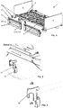
- Fig. 1 shows a conventional bed comprising a bed frame 3, 4.
- Different elements of a mattress support are attached to the frame 3, 4 and are partially adjustable with respect to the frame. For example, a backrest or a foot part can be adjusted.
- two side guards 10 are shown per bed side, each having about half the length of the bed, so that in the combination they can cover the entire length of the bed and thus prevent a person in bed from falling out.
- the type of attachment of the safety side 10 is shown in detail in FIG Fig. 2 shown.
- a connecting part 20 is used for this, as shown in FIG Fig. 7 is shown in the state of attachment to the bed frame 4 in detail.
- the connection part 20 can be designed as a lasered sheet metal part and have a connection area at one end for connection to the safety side 10.
- This connection is preferably a screw connection and the safety side 10 is preferably provided with the connecting part 20 at the factory.
- the connecting part which is used to connect to the frame 3, 4 of the bed, there are two hook-shaped engagement portions 22, 23 (see Fig. 5 and 7th ) intended.
- Frankings 8 are provided which can be brought into engagement with the engagement sections 22, 23.
- Fig. 2 shows two pairs of the frankings 8 in order to be able to fasten the connecting parts 20 of two side guards 10 in the middle of the bed.
- the safety side can be constructed in different ways. It preferably comprises two posts 16 and, relative to the posts, a vertically displaceable longitudinal spar 18.
- the posts themselves can be mounted so as to be vertically displaceable or an upper end include that is foldable or removable.
- an upper handrail 17 can optionally be used, which further increases the overall height of the safety side.
- the engagement sections 22, 23 have an essentially horizontal section and a second, essentially vertical section angled downward therefrom.
- the hook-shaped engagement portions 22, 23 engage in the material of the frame 3, 4 of the bed or through it. They have a distance from one another that is selected to be as large as possible in order to increase the rigidity of the connection.
- a downwardly directed section of the engagement section 23 engages from above into an overhead opening of the frame 4.
- the hook has a vertically aligned and wedge-shaped slot, the width of which at the opening of the slot below is wider (preferably at least 1.5 times) the wall thickness of the bed frame 4.
- the slot is narrower than the wall thickness of the material of the frame.
- the width and position of the slot is dimensioned such that a section of the frame 3, 4 is pressed into the slot.
- the connecting part 20 does not lie on the entire lasered cut surface of the opening 8. Rather, the weight forces are transmitted via contact points (preferably two), the contact points being able to arise at the edges of the laser-cut openings of the frame 3, 4.
- the forces that cause the aforementioned pressing are initially the weight forces of the attachment.
- these are resilient forces of a resiliently acting means 32 explained below.
- a holder 30, or in particular a lever 30, can bring about correspondingly directed forces.
- connection described above can be designed without play in such a way that a wedge-like extension is provided on the hook 23.
- the lower end of the hook 23 is thus slightly trapezoidal.
- the above-mentioned backlash-free connections are, in particular, backlash-free with respect to a torque about an axis in the longitudinal direction of the bed. This means that if you press the upper end of the safety side, that is to say on the handrail 17, in the transverse direction of the bed when the safety side is in the securing position, hardly any deformation is obtained. This gives the user the impression of high quality workmanship.
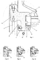
- a bearing pin 25 (see Fig. 5 ) stored, which in turn opposite a bracket or a lever 30 (see Fig. 8 ) is stored.
- the lever 30 can be pivoted relative to the connecting part 20, as is the case in the sequence of Figures 8 to 10 is shown.
- Fig. 8 the state is shown how the engagement portions 22, 23 are inserted into the openings 8 of the frame during assembly.
- the connecting part is pivoted into the openings 8, in particular slightly inclined about the longitudinal direction of the bed. It can be pushed horizontally into the openings 8 and then lowered vertically into the end position. In this state, the lever 30 is in its open position.
- the lever 30 When the lever 30 is closed by the user, he first reaches the in Fig. 9 position shown, in which the resilient means 32 are maximally deformed. These means can preferably be implemented by elastic deformation of the lever 30.
- the lever 30 is made, for example, from an impact-resistant plastic, such as, for example, from polyamide or POM. Hard rubber is also suitable for this. In order to achieve sufficient deformability, a clearance is molded into the lever 30. After the greatest resistance to closing the lever in the in Fig. 10 The point shown, which is at approx. 45 °, the resistance decreases and towards the end of the closing movement this deformation ensures that a force is created that pushes the lever into the closed position.
- a locking element which can preferably be a lever and / or bolt 40 and / or slide, creates a force that presses the hook-shaped elements 22, 23 into a latching mechanism provided for this purpose in the connection with the frame 4.
- a locking element which can preferably be a lever and / or bolt 40 and / or slide, creates a force that presses the hook-shaped elements 22, 23 into a latching mechanism provided for this purpose in the connection with the frame 4.
- a further securing of the holder 30 in the closed position can optionally be provided.
- This can be achieved by a handpiece with a hand engagement area 36, which in this position brings about a form fit.
- the form fit can be brought about by a bolt, slide or lever which engages in a corresponding catch, preferably a catch on the connecting part 20, alternatively, for example, on the attachment part 10.
- Fig. 5 and 7th an actuator with a grip area 36 with a projection 37, which is mounted on the holder 30 and can engage with a projection 37 in a detent of the connecting part, so that in the engaging position the holder 30 does not move out of the position shown in FIG Fig. 10 can be unfolded in the closed position shown.
- the holder 30 is in contact with the frame 4 at a contact surface 39.
- This contact surface is a path limitation of the adjustment movement of the holder 30.
- This stop has the advantage that the user cannot go wrong. With other means of fastening, such as a screw connection, it depends on the screw force. If the screwing force is too low, the screw connection can open unintentionally, which leads to the result that many users or service technicians screw together with maximum force, which can lead to material damage, such as plastic deformations on the frame.
- the stop 39 has the advantage that a position is reached here which stands for good fastening of the attachment part 10.
- the holder 30 can preferably be designed such that, in the closed position of the holder 30, a force acts on the connection of the connecting part 20 to the frame 4, which force is oriented such that the engagement sections 22, 23 are pulled or pressed into their storage position .
- the above-mentioned further securing of the holder 30 in the closed position can be caused by a frictional connection, i.e. by a pressure clamping element, such as a pressure part, which, for example, is pressed elastically and holds the holder 30 in its desired position via frictional forces.
- a pressure clamping element such as a pressure part
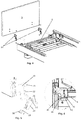
- the connecting part 20 of the Fig. 2 is a flat part, which is attached to the front side of the attachment, in particular the safety side 10. Consequently, the screwing direction of the fastening screws is in the longitudinal direction of the bed.
- Fig. 3 an embodiment is shown in which the connecting part 20 is angled so that it can be screwed from behind against the safety side or side panel. This angled variant can preferably also be used for fastening the heads 5, 6 of the bed.
- the connecting part can be flat in the area of the connection with the head and, in particular, can be aligned perpendicular to the respective post 3, 4. This results in only a relatively small contact zone of these parts with a relatively high surface pressure. This is advantageous because a connection free of play can be realized in this way, if necessary via an elastic and / or partially plastic deformation of the connecting part 20 and the post 3, 4.
- Fig. 6 an alternative mount for the connector 20 is shown.
- a pin 40 is slidably mounted in the connecting part 20 and engages from below under the frame 4 of the bed so that the connecting part 20 cannot be removed.
- a stop 49 is provided for the movement. The user thus has immediate feedback as to whether the pen 40 is in its desired position.
- a form fit 43 is produced in this target position.
- a spring can optionally be provided for the pin 40, which always pushes (or pulls) the pin into the position shown.
- the pin can also be mounted in the frame 3, 4 and have a form-fitting detent with respect to the connecting part 20 or the attachment part 10.
Landscapes
- Health & Medical Sciences (AREA)
- Nursing (AREA)
- Life Sciences & Earth Sciences (AREA)
- Animal Behavior & Ethology (AREA)
- General Health & Medical Sciences (AREA)
- Public Health (AREA)
- Veterinary Medicine (AREA)
- Engineering & Computer Science (AREA)
- General Engineering & Computer Science (AREA)
- Mechanical Engineering (AREA)
- Invalid Beds And Related Equipment (AREA)
Description
- Die vorliegende Erfindung betrifft ein Bett mit einem Anbauteil und ein Verfahren zur Befestigung eines Anbauteils an einem Bett.
- Betten werden in Fabriken gefertigt und anschließend zum Kunden verbracht. Dabei ist es üblich, das Bett (teil-)zerlegt zu liefern, so dass der Kunde oder ein Servicemitarbeiter für die Endmontage verantwortlich ist. Da hierfür möglichst wenig Zeit verwendet werden soll, sind häufig die Betten in größeren Einheiten/Modulen vormontiert, so dass üblicherweise größere Einheiten/Module miteinander verbunden werden müssen. Zudem ist es in anderen Ausführungsformen auch üblich, in der Endmontage vorort die Seitensicherungen, wie auch Blenden und Kopf- und Fußteile mit Verschraubungen an dem Bett zu verbinden. Der erste Fall ist nachteilig, da relativ große und schwere Baugruppen transportiert werden müssen und zusätzlich ist die logistische Flexibilität eingeschränkt, da es einen deutlich erhöhten Aufwand bedeutet, unterschiedliche Varianten bereitzustellen. So müssen in diesem Fall Seitenelemente mit und ohne Seitensicherungen bevorratet werden. Diese Bevorratung kann werkseitig und/oder kundenseitig sein. Der zweite Fall ist nachteilig, da ein zeitlich großer Aufwand des Verschraubens nötig ist. Zudem birgt die Schraubverbindung das Risiko, eine zu große oder zu kleine Anzugskraft zu erfahren. Dies kann zum einen zu einem Lösen der Verbindung und zum anderen zu gestauchten bzw. gequetschten Bauteilen führen. Beispielhafte Verbindungsvorrichtungen für Bettanbauteile sind in den Dokumenten
US 2001/011393 A1 undJP H03 182208 A - Entsprechend ist es die Aufgabe der vorliegenden Erfindung, ein neues Bett bereitzustellen, das einfach, schnell und reproduzierbar montierbar ist. Ebenso ist es die Aufgabe, dass es schnell zerlegbar sein soll. Dies ist gerade im Krankenhaus und Pflegebereich notwendig, wo nicht benötigte Betten schnell und platzsparend verstaut werden müssen.
- Diese Aufgabe wird durch die Merkmale der unabhängigen Ansprüche gelöst. Bevorzugte Weiterbildungen sind Gegenstand der abhängigen Ansprüche.
- Ein Bett umfasst ein seitlich am Bett lösbar angebrachtes Anbauteil, wie insbesondere eine Seitensicherung, wobei für das Anbauteil zwei Verbindungsteile zur Verbindung mit dem Rahmen des Betts vorgesehen sind. Jedes der Verbindungsteile weist zumindest zwei hakenförmige Eingriffsabschnitte für einen Eingriff und/oder ein Umgreifen des Rahmens des Betts auf. Bevorzugt sind die Verbindungsteile mit dem Anbauteil verbunden. So muss an dem Bettrahmen kein gesondertes Teil angebracht bzw. angeschraubt werden. Stattdessen genügt es, wenn an dem Bett, bzw. am Rahmen des Betts Öffnungen vorgesehen sind, mit denen die hakenförmigen Verbindungselemente in Eingriff treten können. So sind am Bett(-rahmen) keine vorstehenden Teile angebracht, von denen eine Verletzungsgefahr ausgehen könnte. Zudem ist die Montage sehr einfach. Die hakenförmigen Eingriffselemente haben erfindungsgemäß einen Versatz in vertikaler Richtung und liegen insbesondere übereinander, wobei auch ein Versatz in Bettquerrichtung erfindungsgemäß vorgesehen ist. Durch diese (zumindest) zwei hakenförmigen Eingriffselemente werden automatisch zwei beabstandete Haltepunkte definiert, was bedeutet, dass hierüber ein Biegemoment aufgenommen werden kann, wenn eine Biegekraft am oberen Ende der Seitensicherung (wenn sie in der sichernden Position ist) in Bettquerrichtung ausgeübt wird. Gerade diese Richtung ist die benötigte Sicherungsrichtung und so ist eine Steifigkeit der Haltevorrichtung in dieser Richtung besonders wichtig. Anstelle von den oben genannten zwei Öffnungen kann eines der hakenförmigen Verbindungselemente alternativ auch so ausgestaltet sein, dass es die Dicke des Bettrahmens in Bettquerrichtung im Bereich der Verhakung komplett umgreift. An den Seiten des Betts, wie auch an den Häuptern des Betts kann ein entsprechendes Anbauteil angebracht werden. Alternativ und äquivalent zu der Verbindung zum Rahmen des Betts kann eine Verbindung zu einem Matratzenträger bestehen. Ein Matratzenträger ist insbesondere eine mit einem Rahmen versehene Struktur, die dazu dient eine Matratze zu tragen.
- Erfindungsgemäß ist für das Verbindungsteil eine offenbare Halterung vorgesehen, die in einem geschlossenen Zustand eingerichtet ist, um eine Entfernung des Anbauteils vom Bettrahmen zu verhindern. Dies kann insbesondere durch eine Einrastung geschehen. Das Anbauteil kann auch eine Seitenblende sein, die bei Verschleiß oder beim Wunsch eines anderen Designs ausgetauscht werden kann. Die öffenbare Halterung ist insbesondere dauerhaft und/oder unentfernbar mit dem Verbindungsteil verbunden. Hierdurch wird eine Sicherung des Anbauteils insbesondere entgegen der Schwerkraftrichtung bewirkt.
- Erfindungsgemäß sind zudem im Rahmen des Betts Freimachungen für die Eingriffselemente vorgesehen und die Eingriffselemente weisen einen vertikalen Versatz auf.
- Insbesondere umfasst die Halterung einen Fingereingriffsbereich, um so ein Öffnen und Schließen der Halterung zu ermöglichen, wobei insbesondere dieses Öffnen und Schließen ohne den Einsatz eines Werkzeugs möglich ist. So ist für den Monteur eine einfache und zeitsparende Endmontage gewährleistet. Dies gilt auch für das Zerlegen und Wiederzusammenbauen im Krankenhaus oder Pflegeheim um Betten platzsparend speichern zu können.
- Bevorzugt ist für die Halterung ein Klemmhebel oder ein Schieber vorgesehen, für den konstruktiv eine Endlage definiert ist, wobei in der Endlage ein Kontakt zu einer Anschlagfläche besteht. Man kann sich im Gegensatz dazu, Verschraubungen zur Halterung vorstellen, diese Verschraubungen wirken mit einer Verschraubkraft, die von der Hand aufgebracht werden muss und die Endlage wird im Gegensatz zum Anschlag durch die Erreichung einer Verschraubungskraft definiert. Für eine gute Dauerfestigkeit der Verschraubung ist eine vordefinierte Verschraubungskraft notwendig, was dafür sorgt, dass eigentlich ein Festziehdrehmoment eingehalten werden müsste. Dies ist aber im betrieblichen Alltag der Montage kaum einzuhalten. Deshalb bietet die Endlage den Vorteil, dass die Soll-Halteposition der Halterung einfach eingestellt und überprüft werden kann.
- Bevorzugt weist das Verbindungsteil bei zumindest einem der hakenförmigen Eingriffsabschnitte einen Spalt auf, der in einem mittleren Bereich der Materialstärke des Bettrahmens entspricht und in dem ein Abschnitt des Bettrahmens aufgenommen ist. Der Spalt kann insbesondere keilförmig sein. In anderen Worten: In bspw. der Mitte des Spalts in Fügerichtung entspricht die Spaltbreite der Materialstärke des Bettrahmens. Alternativ kann er parallele Innenseiten aufweisen. Zusätzlich umfasst diese Formulierung, dass insbesondere in dem Fall, dass der Bettrahmen durch ein Rechteckprofil gebildet wird, der Spalt so breit sein kann, wie die Breite des (Rechteck-)Profils im Außenmaß. Es kann der keilförmige Spalt bevorzugt nur in einem hakenförmigen Eingriffselement vorgesehen sein und dieses hakenförmige Eingriffselement kann dann insbesondere so eingerichtet sein, um die Gewichtskräfte des Anbauteils an den Rahmen des Betts abzuleiten. Die auf das Anbauteil wirkende Schwerkraft drückt bevorzugt den genannten Abschnitt des Bettrahmens in den keilförmigen Spalt.
- Insbesondere ist es vorteilhaft, wenn das Verbindungsteil keine Schrauben zur Verbindung mit dem Rahmen des Betts umfasst und/oder zur Befestigung des Verbindungsteils am Bett benötigt werden. Alternativ und/oder zusätzlich wird bevorzugt keine Schraube vorgesehen, die mit einer Spannkraft die Halterung (also insbesondere den Klemmhebel oder Schieber) in seiner Position hält, da eine Schraube unter Verwendung von Spannkräften arbeitet, die abhängig sind von der Kraft des Anwenders und somit nicht reproduzierbar. Insbesondere kann bei einer Schraube nämlich der Fall auftreten, dass die Schraube zu locker sitzt oder zu fest angezogen wird, so dass ein Schaden am Bett auftreten kann.
- Auch kann unterstützend ein elastisch vorspannbares Mittel vorgesehen sein, um die Halterung in den geschlossenen Zustand zu bewegen und/oder in dem geschlossenen Zustand zu halten. Dabei kann ein geöffneter Zustand der Halterung definiert sein, bei der das Anbauteil vom Bett entnehmbar ist und insbesondere das Verbindungsteil vom Rahmen entnehmbar ist und sobald das Anbauteil befestigt ist, kann für das Schließen des Halteteils, optional zunächst ein erster Wegabschnitt, definiert werden, bei dem praktisch keine Schließkräfte wirken. In einem zweiten Wegabschnitt wirkt bevorzugt bei den meisten Ausführungsformen dieser Erfindung eine Kraft auf die Halterung, die entgegen deren Schließrichtung wirkt und dabei eine Kraft auf die hakenförmige Eingriffsabschnitte in verbindende Richtung bewirkt. Optional und nicht zwingend nötig, kann nach einem Höhepunkt dieser Schließkraft ein dritter Wegabschnitt folgen, bei dem eine Kraft in die Schießrichtung wirkt. Diese Schließkraft kann mit dem Erreichen der Schießposition auf einen kleinen Wert zurückgehen oder Null erreichen. Dies ist der Fall, wenn in einem bevorzugten Ausführungsbeispiel ein federelastisches Mittel 32 der
Fig. 7 verwendet wird. Alternativ kann die federelastische Kraft, die die Rastverbindung schließt einen Maximalwert erreichen, wenn die Schießposition erreicht ist. Dies wäre dann der Fall, wenn die federelastischen Mittel 32 abweichend vonFig. 7 dort angebracht wären, wo das Bezugszeichen 39 ist. - Insbesondere kann das Bett zumindest ein Betthaupt und bevorzugt an jedem Längsende ein Betthaupt umfassen und das Betthaupt kann mit einem lösbaren Verbindungsteil versehen sein, das zumindest zwei hakenförmige Eingriffsabschnitte für einen Eingriff in den Bettrahmen aufweist. Zudem kann bevorzugt eine öffenbare Halterung vorgesehen sein, die in einem geschlossenen Zustand eingerichtet ist, um eine Entfernung des Haupts vom Bettrahmen zu verhindern. Dieses Verbindungsteil kann bevorzugt funktional identisch zu den Verbindungsteilen der seitlichen Anbauteile sein, um die Bedienung zu vereinfachen.
- Vorteilhaft ist ferner, wenn für das Anbauteil ein Verbindungsteil mit dreifacher Sicherung vorgesehen ist, wobei in der ersten Sicherung das Anbauteil durch Schwerkrafteinflüsse am Bett befestigbar ist. In der zweiten Sicherung ist insbesondere durch ein Verbindungsteil eine formschlüssige Verbindung vorgesehen, die eine Entfernung des Anbauteils entgegen der Schwerkraftrichtung behindert. Und in der dritten Sicherung ist eine Sicherung der zweiten Sicherung vorgesehen und insbesondere die dritte Sicherung umfasst eine kraft- und/oder formschlüssige Verbindung. Der Bezug auf die Schwerkraftrichtung umfasst insbesondere, dass zumindest ein Bewegungsanteil (vektoriell) in dieser Richtung gegeben ist. Bevorzugt kann die dritte Sicherung eine kraftschlüssige, wie auch formschlüssige Verbindung umfassen. Der kraftschlüssige Anteil kann bspw. durch Reibkräfte erzielt werden, die gegen ein Öffnen oder Entfernen des Verbindungsteils wirken.
- In einem Verfahren zur Befestigung eines Anbauteils an einem Bett wird das Anbauteil unter Verwendung von der Schwerkraft an einem Rahmen des Betts eingehängt und wird mit einer manuell betätigbaren Halterung an dem Bett befestigt.
- Nachfolgend wird die Erfindung anhand bevorzugter Ausführungsformen beispielhaft erläutert. Es zeigen:
- Fig. 1
- eine perspektivische Ansicht eines Bettes mit einer Seitensicherung in einer Explosionsansicht,
- Fig. 2
- das Detail A der
Fig. 1 mit einer Darstellung eines Verbindungsteils, - Fig. 3
- eine Variante des in
Fig. 2 gezeigten Verbindungsteils, - Fig. 4
- die Möglichkeit der Montage eines Haupts mit einem Verbindungsteil,
- Fig. 5
- das Verbindungsteil in einer perspektivischen Explosionsansicht,
- Fig. 6
- einen Schnitt durch ein Verbindungsteil in einer alternativen Ausführungsform,
- Fig. 7
- einen Schnitt durch das in den
Fig. 1, 2 und5 gezeigten Verbindungsteils im Zustand der Montage an dem Rahmen eines Betts und - Fig. 8 bis 10
- unterschiedliche Zustände während der Montage des Verbindungsteils an das Bett.
-
Fig. 1 zeigt ein übliches Bett, welches einen Bettrahmen 3, 4 umfasst. Am Rahmen 3, 4 sind unterschiedliche Elemente eines Matratzenträgers befestigt und teilweise gegenüber dem Rahmen verstellbar. So sind bspw. eine Rückenlehne oder ein Fußteil anstellbar. Zudem sind pro Bettseite zwei Seitensicherungen 10 gezeigt, die jeweils etwa die Hälfte der Länge des Betts aufweisen, so dass sie in der Kombination die gesamte Bettlängsseite abdecken und so gegen ein Herausfallen einer im Bett befindlichen Person sichern können. Die Art der Befestigung der Seitensicherung 10 ist im Detail derFig. 2 gezeigt. Hierfür kommt nämlich ein Verbindungsteil 20 zum Einsatz, wie es inFig. 7 im Zustand des Anbaus an dem Bettrahmen 4 im Detail gezeigt ist. Das Verbindungsteil 20 kann als ein gelasertes Blechteil ausgeführt sein und an einem Ende einen Verbindungsbereich zur Verbindung mit der Seitensicherung 10 aufweisen. Diese Verbindung ist bevorzugt eine Schraubverbindung und die Seitensicherung 10 wird bevorzugt bereits werkseitig mit dem Verbindungsteil 20 versehen. Am anderen Ende des Verbindungsteils, das der Verbindung mit dem Rahmen 3, 4 des Betts dient, sind zwei hakenförmige Eingriffsabschnitte 22, 23 (sieheFig. 5 und7 ) vorgesehen. Im Rahmen des Betts sind (sieheFig. 2 ) Freimachungen 8 vorgesehen, die in Eingriff mit den Eingriffsabschnitten 22, 23 bringbar sind.Fig. 2 zeigt zwei Paare der Freimachungen 8, um so die Verbindungsteile 20 zweier Seitensicherungen 10 in der Bettmitte befestigen zu können. - Die Seitensicherung kann unterschiedlich aufgebaut sein. Bevorzugt umfasst sie zwei Pfosten 16 und relativ zu den Pfosten einen vertikal verschiebbar gelagerten Längsholmen 18. Die Pfosten können selbst vertikal verschiebbar gelagert sein oder ein oberes Ende umfassen, das umklappbar oder entfernbar ist. Zudem kann optional eine obere Handreling 17 zum Einsatz kommen, die die Gesamthöhe der Seitensicherung weiter erhöht.
- Die Eingriffsabschnitte 22, 23 weisen einen im Wesentlichen horizontalen Abschnitt und einen davon nach unten abgewinkelten zweiten, im Wesentlichen vertikalen Abschnitt auf. Die hakenförmigen Eingriffsabschnitte 22, 23 greifen in das Material des Rahmens 3, 4 des Betts ein oder durch es hindurch. Dabei haben sie einen Abstand voneinander, der möglichst groß gewählt ist, um so die Steifigkeit der Verbindung zu erhöhen. So greift bspw. ein nach unten gerichteter Abschnitt des Eingriffsabschnitts 23 von oben in eine oben liegende Öffnung des Rahmens 4. Und in der unteren Hälfte, bevorzugt in dem unteren Drittel der vertikal ausgerichteten Wand des Rahmens 4, der insbesondere ein Rechteckprofil ist, greift bevorzugt von außen der andere Eingriffsabschnitt 22 ein. Dabei hat der Haken einen vertikal ausgerichteten und keilförmigen Schlitz, dessen Breite an der untenliegenden Öffnung des Schlitzes breiter (bevorzugt mindestens dem 1,5 fachen) der Wandstärke des Bettrahmens 4 entspricht. An dem anderen Ende des Schlitzes, nämlich dem obenliegenden Ende, ist der Schlitz enger als die Wandstärke des Materials des Rahmens. Die Breite und Lage des Schlitzes ist so dimensioniert, dass ein Abschnitt des Rahmens 3, 4 in dem Schlitz eingepresst wird. Das Verbindungsteil 20 liegt insbesondere nicht auf der gesamten gelaserten Schnittfläche der Öffnung 8 auf. Vielmehr werden die Gewichtskräfte über Kontaktpunkte (bevorzugt zwei) übertragen, wobei die Kontaktpunkte sich an den Kanten der gelaserten Öffnungen des Rahmens 3, 4 ergeben können. Die Kräfte, die das vorstehend genannte Pressen bewirken, sind zunächst die Gewichtskräfte des Anbauteils. Zudem sind dies federelastische Kräfte eines nachfolgend erläuterten federelastisch wirkenden Mittels 32. Zudem oder alternativ kann eine Halterung 30, oder insbesondere ein Hebel 30, entsprechend gerichtete Kräfte bewirken. Diese Kräfte bewirken hohe Kontaktkräfte im beschriebenen Schlitz. Diese Kräfte führen dazu, dass eine elastische und/oder plastische Verformung einer Pulverbeschichtung (sofern vorhanden) und/oder Lackierung (sofern vorhanden) und/oder des Materials des Verbindungsteils und/oder des Materials des Rahmens 3, 4 stattfindet. Hierdurch wird eine spielfreie Verbindung geschaffen. Zudem oder alternativ kann die vorstehend beschriebene Verbindung derart spielfrei ausgeführt sein, dass an dem Haken 23 eine keilartige Erweiterung vorgesehen ist. Das untere Ende des Hakens 23 ist also leicht trapezförmig. Die vorstehend genannten spielfreien Verbindungen sind insbesondere spielfrei gegenüber einem Drehmoment um eine Achse in Bettlängsrichtung. Dies bedeutet, dass, wenn man bei einer Seitensicherung in der sichernden Stellung an das obere Ende der Seitensicherung, also an der Handreling 17, in Bettquerrichtung drückt, kaum eine Verformung erhält. Dies bewirkt bei dem Anwender den Eindruck einer wertigen Verarbeitung.
- In einem Drehpunkt 38 (siehe
Fig. 7 ) des Verbindungsteils 20 ist ein Lagerstift 25 (sieheFig. 5 ) gelagert, der seinerseits gegenüber einer Halterung bzw. einem Hebel 30 (sieheFig. 8 ) gelagert ist. Bspw. auf diese Weise ist der Hebel 30 gegenüber dem Verbindungsteil 20 schwenkbar, wie dies in der Abfolge derFig. 8 bis 10 gezeigt ist. So ist inFig. 8 der Zustand gezeigt, wie bei der Montage die Eingriffsabschnitte 22, 23 in die Öffnungen 8 des Rahmens eingeführt sind. Dabei wird das Verbindungsteil insbesondere leicht um die Bettlängsrichtung geneigt in die Öffnungen 8 geschwenkt. Es kann horizontal in die Öffnungen 8 eingeschoben und anschließend vertikal in die Endposition abgelassen werden. In diesem Zustand ist der Hebel 30 in seiner geöffneten Stellung. Wenn der Hebel 30 durch den Anwender geschlossen wird, so erreicht er zunächst die inFig. 9 gezeigte Stellung, bei der federelastische Mittel 32 maximal verformt sind. Bevorzugt können diese Mittel durch eine elastische Verformung des Hebels 30 realisiert werden. Der Hebel 30 ist bspw. aus einem schlagzähen Kunststoff, wie z.B. aus Polyamid oder POM gefertigt. Auch ein Hartgummi ist hierfür geeignet. Um eine hinreichende Verformbarkeit zu erzielen, ist eine Freimachung in den Hebel 30 eingeformt. Nach dem größten Widerstand gegen das Schließen des Hebels in die inFig. 10 gezeigte Stelle, der bei ca. 45° liegt, nimmt der Widerstand ab und gegen Ende der Schließbewegung sorgt diese Verformung dafür, dass eine Kraft entsteht, die den Hebel in die geschlossene Position drückt. Insbesondere oder alternativ entsteht durch ein Verriegelungselement, das bevorzugt ein Hebel und/oder Riegel 40 und/oder Schieber sein kann, eine Kraft, die die hakenförmigen Elemente 22, 23 in eine jeweils dafür vorgesehene Rast der Verbindung mit dem Rahmen 4 drückt. Bei dem Schließen der Halterung 30, 40, das wie ein Verriegelungselement wirkt, bewegen sich zwei Teile unter Druckkraft relativ zueinander, was dazu führt, dass die Halterung auch aufgrund von Reibkräften in der geschlossenen Position verbleibt. - Zudem kann optional eine weitere Sicherung der Halterung 30 in der geschlossenen Position vorgesehen sein. Dies kann durch ein Handstück mit einem Handeingriffsbereich 36 erzielt werden, das in dieser Position einen Formschluss bewirkt. Konstruktiv kann der Formschluss über einen Riegel, Schieber oder Hebel bewirkt werden, der in eine entsprechende Rast, bevorzugt eine Rast an dem Verbindungsteil 20, alternativ bspw. an dem Anbauteil 10, eingreift. Beispielhaft zeigt
Fig. 5 und7 einen Betätiger mit einem Griffbereich 36 mit einem Vorsprung 37, der auf der Halterung 30 gelagert ist und mit einem Vorsprung 37 in eine Rast des Verbindungsteils eingreifen kann, so dass in der eingreifenden Position die Halterung 30 nicht aus der inFig. 10 gezeigten geschlossenen Position aufgeklappt werden kann. In dieser Position steht die Halterung 30 bei einer Kontaktfläche 39 in Kontakt mit dem Rahmen 4. Diese Kontaktfläche ist eine Wegbegrenzung der Einstellbewegung der Halterung 30. - Dieser Anschlag hat den Vorteil, dass der Anwender nichts falsch machen kann. Bei anderen Mitteln der Befestigung, wie z.B. einer Verschraubung, kommt es nämlich auf die Schraubkraft an. Bei einer zu geringen Schraubkraft kann die Verschraubung sich unbeabsichtigt öffnen, was zu dem Ergebnis führt, dass viele Anwender, bzw. Servicetechniker, mit maximaler Kraft verschrauben, was zu Materialschädigungen, wie z.B. plastischen Verformungen am Rahmen führen kann. Der Anschlag 39 hingegen hat den Vorteil, dass hier eine Position erreicht wird, die für eine gute Befestigung des Anbauteils 10 steht. Bevorzugt kann die Halterung 30 so ausgeführt sein, dass in der geschlossenen Position der Halterung 30 eine Kraft auf die Verbindung des Verbindungsteils 20 mit dem Rahmen 4 wirkt, die so ausgerichtet ist, dass die Eingriffsabschnitte 22, 23 in ihre Lagerposition gezogen bzw. gedrückt werden. Alternativ kann die oben genannte weitere Sicherung der Halterung 30 in der geschlossenen Position durch einen Kraftschluss, also durch ein Druckspannelement, verursacht werden, wie bspw. ein Andruckteil, welches bspw. federelastisch angedrückt wird und über Reibkräfte die Halterung 30 in ihrer Sollposition hält.
- Das Verbindungsteil 20 der
Fig. 2 ist ein flaches Teil, welches stirnseitig an dem Anbauteil, insbesondere der Seitensicherung 10 befestigt wird. Folglich ist die Schraubrichtung der Befestigungsschrauben in Bettlängsrichtung. Im Gegensatz dazu ist inFig. 3 eine Ausführungsform gezeigt, bei der das Verbindungsteil 20 abgewinkelt ist, so dass es von hinten gegen die Seitensicherung oder Seitenblende geschraubt werden kann. Diese abgewinkelte Variante kann bevorzugt auch für die Befestigung der Häupter 5, 6 des Betts verwendet werden. Das Verbindungsteil kann in dem Bereich der Verbindung mit dem Haupt flach sein und insbesondere senkrecht zu dem jeweiligen Pfosten 3, 4 ausgerichtet sein. So ergibt sich nur eine relativ geringflächige Kontaktzone dieser Teile mit einer relativ hohen Flächenpressung. Dies ist vorteilhaft, da so ggf. über eine elastische und/oder teilplastische Verformung des Verbindungsteils 20 und des Pfostens 3, 4, eine spielfreie Verbindung realisiert werden kann. - In
Fig. 6 ist eine alternative Halterung für das Verbindungsteil 20 gezeigt. Hier ist ein Stift 40 in dem Verbindungsteil 20 verschiebbar gelagert und greift von unten unter den Rahmen 4 des Betts, dass das Verbindungsteil 20 nicht entfernt werden kann. Ein Anschlag 49 ist für die Bewegung vorgesehen. Somit hat der Anwender eine unmittelbare Rückmeldung, ob der Stift 40 in seiner Sollposition ist. In dieser Sollposition wird ein Formschluss 43 bewirkt. Aus Gründen der einfachen Darstellung ist in dieser Figur eine optionale Sicherung des Stifts 40 gegen ein komplettes Herausziehen nicht dargestellt. Zudem kann für den Stift 40 optional eine Feder vorgesehen sein, die den Stift stets in die gezeigte Lage drückt (oder zieht). - Alternativ kann der Stift auch in dem Rahmen 3, 4 gelagert sein und eine formschlüssige Rast gegenüber dem Verbindungsteil 20 oder dem Anbauteil 10 aufweisen.
Claims (9)
- Bett (1) mit einem seitlich am Bett (1) lösbar angebrachten Anbauteil (10), wie insbesondere einer Seitensicherung (10), wobei für das Anbauteil (10) zwei Verbindungsteile (20) zur Verbindung mit dem Rahmen (3, 4) des Betts (1) vorgesehen sind, und jedes der Verbindungsteile (20) zumindest zwei hakenförmige Eingriffsabschnitte (22, 23) für einen Eingriff in den Rahmen (3, 4) und/oder ein Umgreifen des Rahmens (3, 4) aufweist,
und die hakenförmigen Eingriffsabschnitte (22, 23) einen Versatz in vertikaler Richtung und in Bettquerrichtung aufweisen und wobei für jedes der Verbindungsteile (20) eine öffenbare Halterung (30, 40) vorgesehen ist, die in einem geschlossenen Zustand eingerichtet ist, eine Entfernung des Anbauteils (10) vom Bettrahmen (3, 4) zu verhindern. - Bett (1) gemäß Anspruch 1, wobei die Halterung (30, 40) einen Fingereingriffsbereich (36, 46) umfasst, um so ein Öffnen und Schließen der Halterung (30, 40) zu ermöglichen, wobei insbesondere dieses Öffnen und Schließen ohne den Einsatz eines Werkzeugs möglich ist.
- Bett (1) gemäß einem der Ansprüche 1 oder 2, wobei die Halterung (30, 40) einen Klemmhebel (30) oder einen Schieber (40) umfasst, für den konstruktiv eine Endlage vorgesehen ist, wobei in der Endlage ein Kontakt zu einer Anschlagfläche (39, 49) besteht.
- Bett (1) gemäß einem der Ansprüche 2 oder 3, wobei das Verbindungsteil (20) bei zumindest einem der hakenförmigen Eingriffsabschnitte (22, 23) einen keilförmigen Spalt aufweist, der in einem mittleren Bereich der Materialstärke des Bettrahmens (3, 4) entspricht und in dem ein Abschnitt des Bettrahmens aufgenommen ist, und insbesondere nur in einem hakenförmigen Eingriffselement (22) der keilförmige Spalt vorgesehen ist und dieses hakenförmige Eingriffselement (22) eingerichtet ist, die Gewichtskräfte des Anbauteils (10) an den Rahmen (3, 4) des Betts abzuleiten.
- Bett gemäß einem der Ansprüche 2 oder 3, wobei das Verbindungsteil (20) keine Schraube zur Verbindung mit dem Rahmen (3, 4) des Betts umfasst.
- Bett gemäß einem der Ansprüche 2 oder 3, wobei ein elastisch vorspannbares Mittel (32) vorgesehen ist, um die Halterung (30, 40) in den geschlossenen Zustand zu bewegen und/oder in dem geschlossenen Zustand zu halten.
- Bett gemäß einem der Ansprüche 2 oder 3, wobei das Bett (1) zumindest ein Betthaupt (5, 6) und bevorzugt an jedem Längsende ein Betthaupt (5, 6) umfasst und das Betthaupt (5, 6) mit einem lösbaren Verbindungsteil versehen ist, das zumindest zwei hakenförmige Eingriffsabschnitte für einen Eingriff in den Bettrahmen (3, 4) aufweist und insbesondere und eine öffenbare Halterung vorgesehen ist, die in einem geschlossenen Zustand eingerichtet ist, eine Entfernung des Haupts (5, 6) vom Bettrahmen (3 ,4) zu verhindern.
- Bett gemäß einem der vorangegangenen Ansprüche, wobei für das Anbauteil (10) ein Verbindungsteil (20) mit dreifacher Sicherung vorgesehen ist, wobei in der ersten Sicherung das Anbauteil (10) durch Schwerkrafteinflüsse am Bett befestigbar ist, in der zweiten Sicherung eine formschlüssige Halterung (30) vorgesehen ist, die eine Entfernung des Anbauteils (10) entgegen der Schwerkraftrichtung behindert und in der dritten Sicherung eine Sicherung der zweiten Sicherung vorgesehen ist und insbesondere die dritte Sicherung eine kraft- (32) und/oder formschlüssige (33) Verbindung umfasst.
- Verfahren zur Befestigung eines Anbauteils (10) an einem Bett (1), bei dem das Anbauteil (10) unter Verwendung von der Schwerkraft an einem Rahmen (3, 4) des Betts (1) eingehängt wird und mit einer manuell betätigbaren Halterung (30, 40) an dem Bett (1) befestigt wird, wobei für das Anbauteil (10) zwei Verbindungsteile (20) zur Verbindung mit dem Rahmen (3, 4) des Betts (1) vorgesehen sind und jedes der Verbindungsteile (20) zwei hakenförmige Eingriffsabschnitte (22, 23) für einen Eingriff und/oder ein Umgreifen des Rahmens (3, 4) aufweist, und die hakenförmigen Eingriffsabschnitte (22, 23) einen Versatz in vertikaler Richtung und in Bettquerrichtung J Z aufweisen und für jedes der Verbindungsteile (20) eine öffenbare Halterung (30, 40) vorgesehen ist, die in einem geschlossenen Zustand eine Entfernung des Anbauteils (10) vom Bettrahmen (3, 4) verhindert.
Priority Applications (1)
| Application Number | Priority Date | Filing Date | Title |
|---|---|---|---|
| PL18196144T PL3473228T3 (pl) | 2017-10-17 | 2018-09-24 | Łóżko z częścią dołączaną |
Applications Claiming Priority (1)
| Application Number | Priority Date | Filing Date | Title |
|---|---|---|---|
| DE102017124172.8A DE102017124172A1 (de) | 2017-10-17 | 2017-10-17 | Bett mit Anbauteil |
Publications (2)
| Publication Number | Publication Date |
|---|---|
| EP3473228A1 EP3473228A1 (de) | 2019-04-24 |
| EP3473228B1 true EP3473228B1 (de) | 2021-06-09 |
Family
ID=63682999
Family Applications (1)
| Application Number | Title | Priority Date | Filing Date |
|---|---|---|---|
| EP18196144.2A Active EP3473228B1 (de) | 2017-10-17 | 2018-09-24 | Bett mit anbauteil |
Country Status (3)
| Country | Link |
|---|---|
| EP (1) | EP3473228B1 (de) |
| DE (1) | DE102017124172A1 (de) |
| PL (1) | PL3473228T3 (de) |
Families Citing this family (1)
| Publication number | Priority date | Publication date | Assignee | Title |
|---|---|---|---|---|
| CN111839073B (zh) * | 2020-06-30 | 2022-01-11 | 库甲(广东)家居科技有限公司 | 一种防坠式学生床 |
Family Cites Families (5)
| Publication number | Priority date | Publication date | Assignee | Title |
|---|---|---|---|---|
| US2261820A (en) * | 1940-07-10 | 1941-11-04 | Zimtbaum Arthur | Connector for bed rails |
| US4148106A (en) * | 1977-12-27 | 1979-04-10 | Gallien John W | Furniture fastener system |
| JPH03182208A (ja) * | 1989-12-08 | 1991-08-08 | Paramaunto Bed Kk | 寝台用付属品の取付機構 |
| US5878452A (en) * | 1996-12-03 | 1999-03-09 | Hill-Rom, Inc. | Long term care bed controls |
| CN102499835A (zh) * | 2011-12-23 | 2012-06-20 | 江苏永发医用设备有限公司 | 医用床床头板与床架的锁紧装置 |
-
2017
- 2017-10-17 DE DE102017124172.8A patent/DE102017124172A1/de active Pending
-
2018
- 2018-09-24 EP EP18196144.2A patent/EP3473228B1/de active Active
- 2018-09-24 PL PL18196144T patent/PL3473228T3/pl unknown
Non-Patent Citations (1)
| Title |
|---|
| None * |
Also Published As
| Publication number | Publication date |
|---|---|
| EP3473228A1 (de) | 2019-04-24 |
| DE102017124172A1 (de) | 2019-04-18 |
| PL3473228T3 (pl) | 2021-12-13 |
Similar Documents
| Publication | Publication Date | Title |
|---|---|---|
| EP2531065B1 (de) | Schubladenzarge | |
| DE102006016045B4 (de) | Vorrichtung zur lösbaren Halterung von einem Flächenelement und deren Verwendung | |
| EP3556978A1 (de) | Vorrichtung zur bewegung eines an einem möbelkorpus eines möbels aufgenommenen möbelteils | |
| DE102010017174B4 (de) | Gelenk und klappbares Möbelteil | |
| WO2018033221A1 (de) | Möbelscharnier | |
| EP2294957B1 (de) | Vorrichtung zur Halterung von flächenförmigen Elementen | |
| EP3473228B1 (de) | Bett mit anbauteil | |
| EP2628411A2 (de) | Auszug | |
| EP3745920B1 (de) | Zarge für einen schubkasten | |
| DE202007012830U1 (de) | Varioträger | |
| EP0503234A1 (de) | Schubkastenführung, insbesondere für Schubkästen aus Metall | |
| EP1777363B1 (de) | Vorrichtung zum Arretieren einer Tür eines Gehäuses | |
| DE202008010113U1 (de) | Möbelsystem | |
| EP3033961B1 (de) | Gurtschnallenanordnung | |
| DE3929914A1 (de) | Vorrichtung zur sicherung von einzugsspalten an bandfoerderern | |
| AT509417B1 (de) | Vorrichtung zum befestigen einer funktionseinheit in einem möbelkorpus | |
| EP3771847A1 (de) | Riemenschloss und riemen | |
| DE102004027855A1 (de) | Schutzgitter mit griffförmiger Falle | |
| EP0006439B2 (de) | Vorrichtung zur Stossstellenüberlappung an Stulpschienen | |
| DE202005013975U1 (de) | Einrichtung zum Fixieren von Bauteilen | |
| EP3705676B1 (de) | Verfahren zur montage eines rollladenkastens und auf einem rahmenteil aufgesetzter rollladenkasten | |
| WO1996028319A1 (de) | Gestell für warndreiecke | |
| DE102020126347B3 (de) | Abstandhalter, Führungsschiene für einen Raffstore oder eine Jalousie sowie Raffstore und Jalousie und Verfahren hierfür | |
| EP3860400B1 (de) | Befestigungsvorrichtung für eine blende eines schubkastens an einer zarge | |
| DE102017102921B4 (de) | Seitensicherung für ein Bett und Verfahren zum Aufbau |
Legal Events
| Date | Code | Title | Description |
|---|---|---|---|
| PUAI | Public reference made under article 153(3) epc to a published international application that has entered the european phase |
Free format text: ORIGINAL CODE: 0009012 |
|
| STAA | Information on the status of an ep patent application or granted ep patent |
Free format text: STATUS: THE APPLICATION HAS BEEN PUBLISHED |
|
| AK | Designated contracting states |
Kind code of ref document: A1 Designated state(s): AL AT BE BG CH CY CZ DE DK EE ES FI FR GB GR HR HU IE IS IT LI LT LU LV MC MK MT NL NO PL PT RO RS SE SI SK SM TR |
|
| AX | Request for extension of the european patent |
Extension state: BA ME |
|
| STAA | Information on the status of an ep patent application or granted ep patent |
Free format text: STATUS: REQUEST FOR EXAMINATION WAS MADE |
|
| 17P | Request for examination filed |
Effective date: 20191023 |
|
| RBV | Designated contracting states (corrected) |
Designated state(s): AL AT BE BG CH CY CZ DE DK EE ES FI FR GB GR HR HU IE IS IT LI LT LU LV MC MK MT NL NO PL PT RO RS SE SI SK SM TR |
|
| STAA | Information on the status of an ep patent application or granted ep patent |
Free format text: STATUS: EXAMINATION IS IN PROGRESS |
|
| 17Q | First examination report despatched |
Effective date: 20200228 |
|
| GRAP | Despatch of communication of intention to grant a patent |
Free format text: ORIGINAL CODE: EPIDOSNIGR1 |
|
| STAA | Information on the status of an ep patent application or granted ep patent |
Free format text: STATUS: GRANT OF PATENT IS INTENDED |
|
| INTG | Intention to grant announced |
Effective date: 20201209 |
|
| GRAS | Grant fee paid |
Free format text: ORIGINAL CODE: EPIDOSNIGR3 |
|
| GRAJ | Information related to disapproval of communication of intention to grant by the applicant or resumption of examination proceedings by the epo deleted |
Free format text: ORIGINAL CODE: EPIDOSDIGR1 |
|
| GRAL | Information related to payment of fee for publishing/printing deleted |
Free format text: ORIGINAL CODE: EPIDOSDIGR3 |
|
| STAA | Information on the status of an ep patent application or granted ep patent |
Free format text: STATUS: EXAMINATION IS IN PROGRESS |
|
| GRAP | Despatch of communication of intention to grant a patent |
Free format text: ORIGINAL CODE: EPIDOSNIGR1 |
|
| STAA | Information on the status of an ep patent application or granted ep patent |
Free format text: STATUS: GRANT OF PATENT IS INTENDED |
|
| GRAA | (expected) grant |
Free format text: ORIGINAL CODE: 0009210 |
|
| STAA | Information on the status of an ep patent application or granted ep patent |
Free format text: STATUS: THE PATENT HAS BEEN GRANTED |
|
| INTC | Intention to grant announced (deleted) | ||
| INTG | Intention to grant announced |
Effective date: 20210423 |
|
| AK | Designated contracting states |
Kind code of ref document: B1 Designated state(s): AL AT BE BG CH CY CZ DE DK EE ES FI FR GB GR HR HU IE IS IT LI LT LU LV MC MK MT NL NO PL PT RO RS SE SI SK SM TR |
|
| REG | Reference to a national code |
Ref country code: GB Ref legal event code: FG4D Free format text: NOT ENGLISH |
|
| REG | Reference to a national code |
Ref country code: CH Ref legal event code: EP Ref country code: AT Ref legal event code: REF Ref document number: 1399878 Country of ref document: AT Kind code of ref document: T Effective date: 20210615 |
|
| REG | Reference to a national code |
Ref country code: DE Ref legal event code: R096 Ref document number: 502018005598 Country of ref document: DE |
|
| REG | Reference to a national code |
Ref country code: IE Ref legal event code: FG4D Free format text: LANGUAGE OF EP DOCUMENT: GERMAN |
|
| REG | Reference to a national code |
Ref country code: NL Ref legal event code: FP |
|
| REG | Reference to a national code |
Ref country code: LT Ref legal event code: MG9D |
|
| PG25 | Lapsed in a contracting state [announced via postgrant information from national office to epo] |
Ref country code: LT Free format text: LAPSE BECAUSE OF FAILURE TO SUBMIT A TRANSLATION OF THE DESCRIPTION OR TO PAY THE FEE WITHIN THE PRESCRIBED TIME-LIMIT Effective date: 20210609 Ref country code: HR Free format text: LAPSE BECAUSE OF FAILURE TO SUBMIT A TRANSLATION OF THE DESCRIPTION OR TO PAY THE FEE WITHIN THE PRESCRIBED TIME-LIMIT Effective date: 20210609 Ref country code: FI Free format text: LAPSE BECAUSE OF FAILURE TO SUBMIT A TRANSLATION OF THE DESCRIPTION OR TO PAY THE FEE WITHIN THE PRESCRIBED TIME-LIMIT Effective date: 20210609 Ref country code: BG Free format text: LAPSE BECAUSE OF FAILURE TO SUBMIT A TRANSLATION OF THE DESCRIPTION OR TO PAY THE FEE WITHIN THE PRESCRIBED TIME-LIMIT Effective date: 20210909 |
|
| PG25 | Lapsed in a contracting state [announced via postgrant information from national office to epo] |
Ref country code: NO Free format text: LAPSE BECAUSE OF FAILURE TO SUBMIT A TRANSLATION OF THE DESCRIPTION OR TO PAY THE FEE WITHIN THE PRESCRIBED TIME-LIMIT Effective date: 20210909 Ref country code: LV Free format text: LAPSE BECAUSE OF FAILURE TO SUBMIT A TRANSLATION OF THE DESCRIPTION OR TO PAY THE FEE WITHIN THE PRESCRIBED TIME-LIMIT Effective date: 20210609 Ref country code: RS Free format text: LAPSE BECAUSE OF FAILURE TO SUBMIT A TRANSLATION OF THE DESCRIPTION OR TO PAY THE FEE WITHIN THE PRESCRIBED TIME-LIMIT Effective date: 20210609 Ref country code: SE Free format text: LAPSE BECAUSE OF FAILURE TO SUBMIT A TRANSLATION OF THE DESCRIPTION OR TO PAY THE FEE WITHIN THE PRESCRIBED TIME-LIMIT Effective date: 20210609 Ref country code: GR Free format text: LAPSE BECAUSE OF FAILURE TO SUBMIT A TRANSLATION OF THE DESCRIPTION OR TO PAY THE FEE WITHIN THE PRESCRIBED TIME-LIMIT Effective date: 20210910 |
|
| PG25 | Lapsed in a contracting state [announced via postgrant information from national office to epo] |
Ref country code: RO Free format text: LAPSE BECAUSE OF FAILURE TO SUBMIT A TRANSLATION OF THE DESCRIPTION OR TO PAY THE FEE WITHIN THE PRESCRIBED TIME-LIMIT Effective date: 20210609 Ref country code: PT Free format text: LAPSE BECAUSE OF FAILURE TO SUBMIT A TRANSLATION OF THE DESCRIPTION OR TO PAY THE FEE WITHIN THE PRESCRIBED TIME-LIMIT Effective date: 20211011 Ref country code: SM Free format text: LAPSE BECAUSE OF FAILURE TO SUBMIT A TRANSLATION OF THE DESCRIPTION OR TO PAY THE FEE WITHIN THE PRESCRIBED TIME-LIMIT Effective date: 20210609 Ref country code: SK Free format text: LAPSE BECAUSE OF FAILURE TO SUBMIT A TRANSLATION OF THE DESCRIPTION OR TO PAY THE FEE WITHIN THE PRESCRIBED TIME-LIMIT Effective date: 20210609 Ref country code: EE Free format text: LAPSE BECAUSE OF FAILURE TO SUBMIT A TRANSLATION OF THE DESCRIPTION OR TO PAY THE FEE WITHIN THE PRESCRIBED TIME-LIMIT Effective date: 20210609 Ref country code: ES Free format text: LAPSE BECAUSE OF FAILURE TO SUBMIT A TRANSLATION OF THE DESCRIPTION OR TO PAY THE FEE WITHIN THE PRESCRIBED TIME-LIMIT Effective date: 20210609 |
|
| REG | Reference to a national code |
Ref country code: DE Ref legal event code: R097 Ref document number: 502018005598 Country of ref document: DE |
|
| PLBE | No opposition filed within time limit |
Free format text: ORIGINAL CODE: 0009261 |
|
| STAA | Information on the status of an ep patent application or granted ep patent |
Free format text: STATUS: NO OPPOSITION FILED WITHIN TIME LIMIT |
|
| PG25 | Lapsed in a contracting state [announced via postgrant information from national office to epo] |
Ref country code: DK Free format text: LAPSE BECAUSE OF FAILURE TO SUBMIT A TRANSLATION OF THE DESCRIPTION OR TO PAY THE FEE WITHIN THE PRESCRIBED TIME-LIMIT Effective date: 20210609 |
|
| REG | Reference to a national code |
Ref country code: CH Ref legal event code: PL |
|
| 26N | No opposition filed |
Effective date: 20220310 |
|
| PG25 | Lapsed in a contracting state [announced via postgrant information from national office to epo] |
Ref country code: MC Free format text: LAPSE BECAUSE OF FAILURE TO SUBMIT A TRANSLATION OF THE DESCRIPTION OR TO PAY THE FEE WITHIN THE PRESCRIBED TIME-LIMIT Effective date: 20210609 Ref country code: AL Free format text: LAPSE BECAUSE OF FAILURE TO SUBMIT A TRANSLATION OF THE DESCRIPTION OR TO PAY THE FEE WITHIN THE PRESCRIBED TIME-LIMIT Effective date: 20210609 |
|
| PG25 | Lapsed in a contracting state [announced via postgrant information from national office to epo] |
Ref country code: LU Free format text: LAPSE BECAUSE OF NON-PAYMENT OF DUE FEES Effective date: 20210924 Ref country code: IE Free format text: LAPSE BECAUSE OF NON-PAYMENT OF DUE FEES Effective date: 20210924 |
|
| PG25 | Lapsed in a contracting state [announced via postgrant information from national office to epo] |
Ref country code: LI Free format text: LAPSE BECAUSE OF NON-PAYMENT OF DUE FEES Effective date: 20210930 Ref country code: CH Free format text: LAPSE BECAUSE OF NON-PAYMENT OF DUE FEES Effective date: 20210930 |
|
| PG25 | Lapsed in a contracting state [announced via postgrant information from national office to epo] |
Ref country code: CY Free format text: LAPSE BECAUSE OF FAILURE TO SUBMIT A TRANSLATION OF THE DESCRIPTION OR TO PAY THE FEE WITHIN THE PRESCRIBED TIME-LIMIT Effective date: 20210609 |
|
| P01 | Opt-out of the competence of the unified patent court (upc) registered |
Effective date: 20230530 |
|
| PG25 | Lapsed in a contracting state [announced via postgrant information from national office to epo] |
Ref country code: HU Free format text: LAPSE BECAUSE OF FAILURE TO SUBMIT A TRANSLATION OF THE DESCRIPTION OR TO PAY THE FEE WITHIN THE PRESCRIBED TIME-LIMIT; INVALID AB INITIO Effective date: 20180924 |
|
| PGFP | Annual fee paid to national office [announced via postgrant information from national office to epo] |
Ref country code: NL Payment date: 20230921 Year of fee payment: 6 Ref country code: GB Payment date: 20230913 Year of fee payment: 6 Ref country code: CZ Payment date: 20230823 Year of fee payment: 6 |
|
| PGFP | Annual fee paid to national office [announced via postgrant information from national office to epo] |
Ref country code: PL Payment date: 20230829 Year of fee payment: 6 Ref country code: FR Payment date: 20230913 Year of fee payment: 6 Ref country code: DE Payment date: 20230913 Year of fee payment: 6 Ref country code: BE Payment date: 20230920 Year of fee payment: 6 |
|
| PGFP | Annual fee paid to national office [announced via postgrant information from national office to epo] |
Ref country code: IT Payment date: 20230927 Year of fee payment: 6 |
|
| PG25 | Lapsed in a contracting state [announced via postgrant information from national office to epo] |
Ref country code: MK Free format text: LAPSE BECAUSE OF FAILURE TO SUBMIT A TRANSLATION OF THE DESCRIPTION OR TO PAY THE FEE WITHIN THE PRESCRIBED TIME-LIMIT Effective date: 20210609 |