EP3470599A1 - Osb-platte und verwendung derselbigen - Google Patents
Osb-platte und verwendung derselbigen Download PDFInfo
- Publication number
- EP3470599A1 EP3470599A1 EP17196384.6A EP17196384A EP3470599A1 EP 3470599 A1 EP3470599 A1 EP 3470599A1 EP 17196384 A EP17196384 A EP 17196384A EP 3470599 A1 EP3470599 A1 EP 3470599A1
- Authority
- EP
- European Patent Office
- Prior art keywords
- osb
- fold
- glue
- osb board
- plate
- Prior art date
- Legal status (The legal status is an assumption and is not a legal conclusion. Google has not performed a legal analysis and makes no representation as to the accuracy of the status listed.)
- Granted
Links
Images

Classifications
-
- E—FIXED CONSTRUCTIONS
- E04—BUILDING
- E04F—FINISHING WORK ON BUILDINGS, e.g. STAIRS, FLOORS
- E04F13/00—Coverings or linings, e.g. for walls or ceilings
- E04F13/07—Coverings or linings, e.g. for walls or ceilings composed of covering or lining elements; Sub-structures therefor; Fastening means therefor
- E04F13/08—Coverings or linings, e.g. for walls or ceilings composed of covering or lining elements; Sub-structures therefor; Fastening means therefor composed of a plurality of similar covering or lining elements
- E04F13/0889—Coverings or linings, e.g. for walls or ceilings composed of covering or lining elements; Sub-structures therefor; Fastening means therefor composed of a plurality of similar covering or lining elements characterised by the joints between neighbouring elements, e.g. with joint fillings or with tongue and groove connections
- E04F13/0896—Coverings or linings, e.g. for walls or ceilings composed of covering or lining elements; Sub-structures therefor; Fastening means therefor composed of a plurality of similar covering or lining elements characterised by the joints between neighbouring elements, e.g. with joint fillings or with tongue and groove connections with adhesive joining strips
-
- B—PERFORMING OPERATIONS; TRANSPORTING
- B32—LAYERED PRODUCTS
- B32B—LAYERED PRODUCTS, i.e. PRODUCTS BUILT-UP OF STRATA OF FLAT OR NON-FLAT, e.g. CELLULAR OR HONEYCOMB, FORM
- B32B1/00—Layered products having a non-planar shape
-
- B—PERFORMING OPERATIONS; TRANSPORTING
- B32—LAYERED PRODUCTS
- B32B—LAYERED PRODUCTS, i.e. PRODUCTS BUILT-UP OF STRATA OF FLAT OR NON-FLAT, e.g. CELLULAR OR HONEYCOMB, FORM
- B32B21/00—Layered products comprising a layer of wood, e.g. wood board, veneer, wood particle board
- B32B21/02—Layered products comprising a layer of wood, e.g. wood board, veneer, wood particle board the layer being formed of fibres, chips, or particles, e.g. MDF, HDF, OSB, chipboard, particle board, hardboard
-
- B—PERFORMING OPERATIONS; TRANSPORTING
- B32—LAYERED PRODUCTS
- B32B—LAYERED PRODUCTS, i.e. PRODUCTS BUILT-UP OF STRATA OF FLAT OR NON-FLAT, e.g. CELLULAR OR HONEYCOMB, FORM
- B32B21/00—Layered products comprising a layer of wood, e.g. wood board, veneer, wood particle board
- B32B21/04—Layered products comprising a layer of wood, e.g. wood board, veneer, wood particle board comprising wood as the main or only constituent of a layer, which is next to another layer of the same or of a different material
- B32B21/06—Layered products comprising a layer of wood, e.g. wood board, veneer, wood particle board comprising wood as the main or only constituent of a layer, which is next to another layer of the same or of a different material of paper or cardboard
-
- B—PERFORMING OPERATIONS; TRANSPORTING
- B32—LAYERED PRODUCTS
- B32B—LAYERED PRODUCTS, i.e. PRODUCTS BUILT-UP OF STRATA OF FLAT OR NON-FLAT, e.g. CELLULAR OR HONEYCOMB, FORM
- B32B3/00—Layered products comprising a layer with external or internal discontinuities or unevennesses, or a layer of non-planar shape; Layered products comprising a layer having particular features of form
- B32B3/02—Layered products comprising a layer with external or internal discontinuities or unevennesses, or a layer of non-planar shape; Layered products comprising a layer having particular features of form characterised by features of form at particular places, e.g. in edge regions
- B32B3/06—Layered products comprising a layer with external or internal discontinuities or unevennesses, or a layer of non-planar shape; Layered products comprising a layer having particular features of form characterised by features of form at particular places, e.g. in edge regions for securing layers together; for attaching the product to another member, e.g. to a support, or to another product, e.g. groove/tongue, interlocking
-
- E—FIXED CONSTRUCTIONS
- E04—BUILDING
- E04C—STRUCTURAL ELEMENTS; BUILDING MATERIALS
- E04C2/00—Building elements of relatively thin form for the construction of parts of buildings, e.g. sheet materials, slabs, or panels
- E04C2/02—Building elements of relatively thin form for the construction of parts of buildings, e.g. sheet materials, slabs, or panels characterised by specified materials
- E04C2/10—Building elements of relatively thin form for the construction of parts of buildings, e.g. sheet materials, slabs, or panels characterised by specified materials of wood, fibres, chips, vegetable stems, or the like; of plastics; of foamed products
- E04C2/12—Building elements of relatively thin form for the construction of parts of buildings, e.g. sheet materials, slabs, or panels characterised by specified materials of wood, fibres, chips, vegetable stems, or the like; of plastics; of foamed products of solid wood
-
- E—FIXED CONSTRUCTIONS
- E04—BUILDING
- E04C—STRUCTURAL ELEMENTS; BUILDING MATERIALS
- E04C2/00—Building elements of relatively thin form for the construction of parts of buildings, e.g. sheet materials, slabs, or panels
- E04C2/02—Building elements of relatively thin form for the construction of parts of buildings, e.g. sheet materials, slabs, or panels characterised by specified materials
- E04C2/10—Building elements of relatively thin form for the construction of parts of buildings, e.g. sheet materials, slabs, or panels characterised by specified materials of wood, fibres, chips, vegetable stems, or the like; of plastics; of foamed products
- E04C2/24—Building elements of relatively thin form for the construction of parts of buildings, e.g. sheet materials, slabs, or panels characterised by specified materials of wood, fibres, chips, vegetable stems, or the like; of plastics; of foamed products laminated and composed of materials covered by two or more of groups E04C2/12, E04C2/16, E04C2/20
-
- E—FIXED CONSTRUCTIONS
- E04—BUILDING
- E04F—FINISHING WORK ON BUILDINGS, e.g. STAIRS, FLOORS
- E04F13/00—Coverings or linings, e.g. for walls or ceilings
- E04F13/07—Coverings or linings, e.g. for walls or ceilings composed of covering or lining elements; Sub-structures therefor; Fastening means therefor
- E04F13/08—Coverings or linings, e.g. for walls or ceilings composed of covering or lining elements; Sub-structures therefor; Fastening means therefor composed of a plurality of similar covering or lining elements
- E04F13/0866—Coverings or linings, e.g. for walls or ceilings composed of covering or lining elements; Sub-structures therefor; Fastening means therefor composed of a plurality of similar covering or lining elements composed of several layers, e.g. sandwich panels or layered panels
-
- E—FIXED CONSTRUCTIONS
- E04—BUILDING
- E04F—FINISHING WORK ON BUILDINGS, e.g. STAIRS, FLOORS
- E04F13/00—Coverings or linings, e.g. for walls or ceilings
- E04F13/07—Coverings or linings, e.g. for walls or ceilings composed of covering or lining elements; Sub-structures therefor; Fastening means therefor
- E04F13/08—Coverings or linings, e.g. for walls or ceilings composed of covering or lining elements; Sub-structures therefor; Fastening means therefor composed of a plurality of similar covering or lining elements
- E04F13/0889—Coverings or linings, e.g. for walls or ceilings composed of covering or lining elements; Sub-structures therefor; Fastening means therefor composed of a plurality of similar covering or lining elements characterised by the joints between neighbouring elements, e.g. with joint fillings or with tongue and groove connections
- E04F13/0894—Coverings or linings, e.g. for walls or ceilings composed of covering or lining elements; Sub-structures therefor; Fastening means therefor composed of a plurality of similar covering or lining elements characterised by the joints between neighbouring elements, e.g. with joint fillings or with tongue and groove connections with tongue and groove connections
-
- E—FIXED CONSTRUCTIONS
- E04—BUILDING
- E04F—FINISHING WORK ON BUILDINGS, e.g. STAIRS, FLOORS
- E04F13/00—Coverings or linings, e.g. for walls or ceilings
- E04F13/07—Coverings or linings, e.g. for walls or ceilings composed of covering or lining elements; Sub-structures therefor; Fastening means therefor
- E04F13/08—Coverings or linings, e.g. for walls or ceilings composed of covering or lining elements; Sub-structures therefor; Fastening means therefor composed of a plurality of similar covering or lining elements
- E04F13/10—Coverings or linings, e.g. for walls or ceilings composed of covering or lining elements; Sub-structures therefor; Fastening means therefor composed of a plurality of similar covering or lining elements of wood or with an outer layer of wood
-
- B—PERFORMING OPERATIONS; TRANSPORTING
- B32—LAYERED PRODUCTS
- B32B—LAYERED PRODUCTS, i.e. PRODUCTS BUILT-UP OF STRATA OF FLAT OR NON-FLAT, e.g. CELLULAR OR HONEYCOMB, FORM
- B32B2419/00—Buildings or parts thereof
- B32B2419/06—Roofs, roof membranes
-
- B—PERFORMING OPERATIONS; TRANSPORTING
- B32—LAYERED PRODUCTS
- B32B—LAYERED PRODUCTS, i.e. PRODUCTS BUILT-UP OF STRATA OF FLAT OR NON-FLAT, e.g. CELLULAR OR HONEYCOMB, FORM
- B32B2471/00—Floor coverings
-
- B—PERFORMING OPERATIONS; TRANSPORTING
- B32—LAYERED PRODUCTS
- B32B—LAYERED PRODUCTS, i.e. PRODUCTS BUILT-UP OF STRATA OF FLAT OR NON-FLAT, e.g. CELLULAR OR HONEYCOMB, FORM
- B32B2607/00—Walls, panels
-
- E—FIXED CONSTRUCTIONS
- E04—BUILDING
- E04F—FINISHING WORK ON BUILDINGS, e.g. STAIRS, FLOORS
- E04F13/00—Coverings or linings, e.g. for walls or ceilings
- E04F13/07—Coverings or linings, e.g. for walls or ceilings composed of covering or lining elements; Sub-structures therefor; Fastening means therefor
- E04F13/08—Coverings or linings, e.g. for walls or ceilings composed of covering or lining elements; Sub-structures therefor; Fastening means therefor composed of a plurality of similar covering or lining elements
- E04F13/0864—Coverings or linings, e.g. for walls or ceilings composed of covering or lining elements; Sub-structures therefor; Fastening means therefor composed of a plurality of similar covering or lining elements composed of superposed elements which overlap each other and of which the flat outer surface includes an acute angle with the surface to cover
-
- E—FIXED CONSTRUCTIONS
- E04—BUILDING
- E04F—FINISHING WORK ON BUILDINGS, e.g. STAIRS, FLOORS
- E04F2201/00—Joining sheets or plates or panels
- E04F2201/01—Joining sheets, plates or panels with edges in abutting relationship
- E04F2201/0107—Joining sheets, plates or panels with edges in abutting relationship by moving the sheets, plates or panels substantially in their own plane, perpendicular to the abutting edges
-
- E—FIXED CONSTRUCTIONS
- E04—BUILDING
- E04F—FINISHING WORK ON BUILDINGS, e.g. STAIRS, FLOORS
- E04F2201/00—Joining sheets or plates or panels
- E04F2201/01—Joining sheets, plates or panels with edges in abutting relationship
- E04F2201/0138—Joining sheets, plates or panels with edges in abutting relationship by moving the sheets, plates or panels perpendicular to the main plane
-
- E—FIXED CONSTRUCTIONS
- E04—BUILDING
- E04F—FINISHING WORK ON BUILDINGS, e.g. STAIRS, FLOORS
- E04F2201/00—Joining sheets or plates or panels
- E04F2201/02—Non-undercut connections, e.g. tongue and groove connections
- E04F2201/026—Non-undercut connections, e.g. tongue and groove connections with rabbets, e.g. being stepped
-
- E—FIXED CONSTRUCTIONS
- E04—BUILDING
- E04F—FINISHING WORK ON BUILDINGS, e.g. STAIRS, FLOORS
- E04F2201/00—Joining sheets or plates or panels
- E04F2201/07—Joining sheets or plates or panels with connections using a special adhesive material
Definitions
- the present invention relates to a modified OSB panel with a new connection profile and its use for wall and / or ceiling paneling.
- Coated boards also known as Oriented Strand Board (OSB) boards
- OSB Oriented Strand Board
- OSB boards are wood-based panels made from long slender strands.
- OSB boards are increasingly being used in timber and prefabricated house construction, as OSB boards are lightweight and still meet the structural requirements imposed on building boards.
- OSB boards are used as building boards and as wall or roof planking or in the floor area.
- a fixation is effected, for example, by the formation of a groove provided along a longitudinal and / or transverse edge and a spring formed on the opposite longitudinal and / or transverse edge, wherein the spring engages in the groove (so-called tongue and groove connection ).
- tongue and groove connections are connections which enable a positive locking, for example, of floor panels in a floating installation. Tongue and groove connections interlock and can therefore only be pushed into each other or stuck. In this way, holding forces can be transmitted from a bottom plate in an adjacent adjacent bottom plate in the horizontal direction and unevenness in the soil can be compensated.
- OSB panels for example as wall panels with a tongue and groove connection
- a vertical installation of OSB panels is associated with the user with some effort and thus impractical.
- the individual OSB plates either additionally glued to each other or to fix by screws on beams or wooden frame structures. This is especially necessary for vertical applications.
- OSB boards can be used as building boards, especially in the manufacture of prefabricated houses.
- the wall is made of a solid wooden frame with corresponding beams covered with OSB panels from both sides.
- the space between the frame members is suitably isolated.
- plasterboard is usually very heavy (density over 1200 kg / m 3 ) and requires knowledge and some effort in mounting.
- the surface also requires the application of a plaster layer and special tools are required for cutting purposes.
- the present invention is therefore based on the technical object to overcome the disadvantages of the known systems, and to provide a simple but efficient method that allows the user or processor easy laying OSB panels as wall or ceiling panels without additional cost.
- the provided OSB panels should represent an alternative to the conventionally used gypsum plasterboard.
- an OSB panel having at least two opposing panel edges, particularly two opposing longitudinal edges, each of the two opposing panel edges having a simple fold, the fold in one panel edge being complementary to the fold in the opposite panel edge ,
- At least one glue hose (or a glue cord) is provided in or on at least one of the opposing folds.
- the at least one glue hose is arranged in at least one groove provided in the fold.
- the groove can also be referred to as an insertion channel for the glue hose.
- a fold means a step or joint in a plate (or generally in a body).
- the fold (or paragraph) is provided in each case at the edge or at the edge of the OSB plate and allows a flat juxtaposition of the OSB plates.
- the complementary folds provided on the opposite plate edges form a stepped connection with each other in the connected state.
- a simple fold may also be described as including in the plate edge a straight step of a predetermined depth and width, e.g. is introduced by milling. Accordingly, a step (or fold) is formed in which the edge protrudes in a region of the plate having a predetermined width and protrudes in another region having a predetermined depth.
- the fold stands in a plate edge, e.g. in a lower region of the plate edge and in an upper region, the opposite plate edge having a complementary fold which protrudes in the upper region of the plate edge and protrudes in the lower region.
- the fold according to the invention makes it easy to place the OSB boards on one another.
- the OSB boards according to the invention are also well suited for a planking of a stud work for the production of a wall, in Contrary to the tongue and groove connections, which can only be pushed together or stuck.
- the width of the fold in the opposing plate edges is between 20 and 40 mm, preferably between 25 and 35 mm, particularly preferably 30 mm.
- the fold width is preferably the same in the opposite plate edges. However, it is also generally conceivable that the fold width is different in the opposite plate edges.
- the depth of the fold corresponds to at least one third, preferably equal to at least half the thickness of the OSB board.
- the thickness of the OSB plate may be between 9 and 50 mm, preferably between 10 and 25 mm, in particular at 18 mm. Accordingly, in the case where the folding depth corresponds to half the plate thickness, the depth of the fold is between 4.5 and 25 mm, preferably between 5 and 12.5 mm, in particular 9 mm.
- the fold is introduced by means of suitable tools in the plate.
- suitable tools in the plate.
- a milling and ablation of the wood panel takes place at the edges.
- the glue hose is secured captively on the fold by adhesive dots.
- the opening of the glue hose is made by compressing the seam connection, in particular by the pressure due to additional mechanical connection means, such as nails, clamps or screws.
- the mechanical fasteners compress the folds and also reach into the framework behind it.
- the glue hose can be made perforated and forms a predetermined breaking point for easier opening in these areas of defined weakening.
- the glue hose can also be inserted into a groove and optionally secured by adhesive points captive in the groove.
- this groove is provided only in a fold, in particular in the lower fold; ie in the fold which can be seen in the OSB plate before laying or gluing for the user in plan view.
- the at least one groove for the at least one glue tube extends along the entire length of the plate edge.
- the glue hose or the glue contained in the glue hose is used for bonding the folds as connection points of the OSB plates and for airtightness at the connection of the respective OSB plates.
- the at least one groove for the at least one glue hose with a radius between 1 and 5 mm, preferably between 2 and 4 mm, particularly preferably 3 mm is introduced into the surface of the fold.
- the groove is milled or sawed into the surface of the fold, e.g. by means of a milling cutter or a saw blade with the shape of the groove to be introduced.
- the groove may have a semicircular shape or a flatter, oval shape. In the case of an oval shape of the groove, the cross section of the glue hose would also be made oval.
- the upper fold can be made smooth. This simplifies the production.
- a raised web is provided with alternating symmetrical elevations on the upper fold, which is arranged complementary to the groove in the lower fold.
- the alternating symmetrical elevations cause in an assembly or juxtaposition of opposing folds due to the forces applied thereto or the applied pressure opening or destruction of the inserted in the groove glue hose.
- the adhesive is released and spreads in the area of the fold.
- the elevations or elevations on the at least one fold each have a pointing away from the wood-based panel point-shaped tapered geometry.
- the sides of each survey are preferably the same length. The height and angular dimensions between the sides of the preferably pointed to current surveys can be varied depending on the plate thickness and folding geometry.
- the angular dimensions of the inner angle of the pointed-to-current survey vary, with a small inner angle means a more pointed survey.
- the angle size should be dependent on the material used for the glue hose and the force or pressure to be applied to the opening of the glue hose. If, for example, a stronger material is used for the glue hose, then the Survey relatively acute-angled to allow opening of the glue hose. Conversely, when using a softer material for the glue tube, a less pointed elevation may be sufficient to open the glue tube.
- the elevations may have a height of 1 to 5 mm, preferably 2 to 4 mm.
- the at least one glue hose is formed as a continuous hose, for example in the form of an extruded hose, which contains the glue or adhesive.
- the at least one glue tube is divided along its length into individual segments or chambers.
- the segments or chambers are preferably of the same size, that is, have equal volumes for receiving an equal amount of adhesive.
- the segments or chambers may be formed by welds or so-called sealing sites, e.g. be formed with a width between 1 and 3 mm, preferably 2 mm.
- a subdivision of the tube into segments is possible using perforation lines, wherein the perforation lines can be located on the top and / or the bottom of the glue tube
- the glue hose has a diameter between 3 and 10 mm, preferably 5 and 9 mm.
- the length of a single segment of the glue hose can be between 100 and 200 mm, preferably between 130 and 180 mm, particularly preferably between 150 and 170 mm.
- a glue tube with segments separated by sealing sites has various advantages. So occurs in case of damage to the glue hose) during transport, storage or processing in a segmentation only the adhesive or glue from the damaged segment and accordingly emptying of the entire glue hose is prevented. Furthermore, a segmentation of the glue hose also allows the processing of different formats of wood-based panels, since these must correspond in format only a multiple of the single segment length of the glue hose segments (a separation of the glue hose in the seal is easily possible).
- the glue hose consists of a plastic material.
- the plastic material should be selected so that it has a certain strength, so that a rupture of the hose during the Production and transport of the OSB board is avoided, but can be opened when laying the OSB boards.
- Particularly preferred plastic material used here is polyethylene terephthalate (PET), polyamide (PA) and / or polyethylene (PE) or a mixture thereof.
- PET polyethylene terephthalate
- PA polyamide
- PE polyethylene
- the presently used adhesive is selected from the group comprising polyvinyls and acrylates. Particularly advantageous is the use of aqueous adhesive formulations such as polyvinyl acetate (PVAC) or ethylene vinyl acetate (EVA). Of course, other glues can be used with water as a solvent.
- a PVAC glue having a solids content of between 50 and 80% by weight, preferably between 60 and 79% by weight, particularly preferably 65% by weight, may be used as the adhesive.
- the plate edges each at the top of the plate a rounding with a radius between 3 and 10 mm, preferably between 5 and 8 mm, in particular preferably between 6 and 7 mm; i.e. the plate edges have a corresponding rounding at the protruding and / or the recessed portion of the fold.
- the rounded portions together form a joint of the surface that can be filled.
- a mechanical connection or fastening provided, which preferably extends into the upright of the stud work on which the OSB board is attached.
- Such mechanical attachment can be done with nails, screws or staples.
- a staple consists of two nails that are connected together. The driving of the clamp in the seam connection is done with a pneumatic clamp gun.
- the profile provided according to the invention in an OSB panel has a multiplicity of advantages: For example, a static effect is achieved by the type of overlapping and possible connection. By rounding off the profile surface, the plate impact be filled.
- the overlay 50/50 allows the plate to be clamped over both layers at the joint (at least 30% savings in the clamps).
- Through the groove or insertion channel for a glue hose in the rebate profile a self-sizing and airtight connection between the OSB boards is achieved at the junction. It provides a frictional bond for closed surfaces.
- the OSB panels can be fixed by means of screws or clamps to designated frame, so that storey-high formats can be realized.
- the surface of the OSB panel is provided with at least one ply of paper.
- a first paper layer is impregnated with at least one resin, in particular a formaldehyde resin.
- This first paper layer is in particular a paper layer, which is arranged directly on the OSB surface.
- the formaldehyde resin is, in particular, a melamine-formaldehyde resin, urea-formaldehyde resin, melamine-urea-formaldehyde resin.
- the paper used for the first paper layer has a basis weight between 30 and 200 g / m 2 , preferably between 50 and 150 g / m 2 , particularly preferably between 80 and 120 g / m 2 .
- a second paper layer is provided on the first paper layer, wherein the second paper layer preferably consists of a raw (ie untreated, non-impregnated) paper.
- the basis weight of the base paper of the second paper layer is between 30 and 300 g / m 2 , preferably between 50 and 250 g / m 2 , particularly preferably between 100 and 120 g / m 2 .
- hydrophobic components as protection against climatic influences or a thin metal film for heat reflection on the second paper layer.
- the at least one paper layer is designed in the form of a cardboard.
- the cardboard has a thickness between 0.5 and 5 mm, preferably between 1 and 4 mm, particularly preferably between 2 and 3 mm.
- the thickness of the paperboard can be between 0.8 and 2.6 mm, e.g. at 1, 5 mm.
- the cardboard is preferably laminated onto the surface of the OSB panel prior to the introduction of the rabbet profile into the panel edges.
- an adhesive seal is applied to the top of the OSB and then the cardboard is unrolled on top. Both OSB board and the cardboard box move through the laminating line.
- a line-shaped pressure acts between the rollers, which supports the connection between OSB board and cardboard.
- the at least one cardboard with the OSB plate is pressed in a short-cycle press.
- a resinated paper is first applied to the surface of the OSB plate, on which the cardboard is placed.
- the paper may e.g. be impregnated or impregnated with one or more resins from the group comprising melamine-formaldehyde resin, urea-melamine-formaldehyde resin, phenol-melamine-formaldehyde resin.
- the resin in the resinated paper melts, which acts as an adhesive or adhesive between the OSB surface and cardboard paper.
- the coating of OSB surfaces with paperboard has a number of advantages: By applying it to a plate surface one-sidedly, a smooth coatable surface having the properties of a gypsum board or gypsum fiberboard is provided which has the additional properties of a wood board, such as very good Mounting options (eg by means of screws or clamps) or special dowel has.
- a modified OSB board can be used as a finish surface. Also, the modified OSB boards are static and airtight use.
- the present modified OSB board is used in particular for the production of wall and / or ceiling paneling.
- the present OSB board can be used in various formats.
- OSB boards with a length between 2000-5000 mm, preferably 2500 mm, and a width between 600-2800 mm, preferably between 625-2500 mm, and at the longitudinal edges with the inventive profile of simple fold and glue hose provided.
- the faces are blunt-edged (i.e., not beveled) in this format.
- This OSB board format is used in particular in storey height, the width of the hot press and thus the maximum width of the plate of the height of a floor (floor) correspond during construction.
- the width of the OSB covers an entire storey height (floor height). This is usually done in such buildings, in which the supporting structure is largely realized by a wooden stud - this framework is then stiffened statically stiffening with the OSB in question here. Therefore, the OSBs are bullet high, with the OSB boards blunting (i.e., not seamed) along the floor height.
- the folds are then provided on the OS plates vertical to the storey height.
- OSB plates are provided with a length between 2000-3000 mm, preferably 2500 mm, and a width between 500-1000 mm, preferably 625 mm, and at the longitudinal edges with the inventive profile of simple fold and glue hose.
- the end faces are designed in this format with known tongue and groove profiling, which also here preferably a rounding of the plate edges is provided.
- This OSB board format is used in particular as a laying plate.
- the present OSB panel is also used in a method of joining (or laying) two or more OSB panels having the following features.
- a first OSB board having the above features is bonded to another (second) OSB board having the above features, wherein the fold of a first OSB board is placed on the complementary fold of the further second OSB board and together is pressed, which opened by the compression of the two OSB plates in the fold, and in particular in the groove, provided glue tube and the glue is released from the glue tube.
- the surface can be further processed in analogy to the conventional plasterboard, e.g. Painting, wallpapering etc.
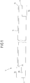
- FIG. 1 shows a schematic cross-sectional view of an OSB plate 1 with a width between 625-2800 mm, which are provided on opposite plate edges 2, 3 each with a simple fold 2a, 3a, wherein both folds 2a, 3a are complementary to each other.
- the fold 2a protrudes in the plate edge 2 in a lower portion of the plate edge 2 and in an upper portion, wherein in the case of the complementary fold 3a, the upper portion of the plate edge 3 protrudes and the lower portion protrudes.
- the width of the two folds 2a, 3a is 30 mm in each case.
- the depth of the folds corresponds in each case to half the thickness of the OSB board; ie with a plate thickness between 9 and 40 mm, the rebate depth is 4.5 to 20 mm.
- a rounded groove 2b is provided as an insertion channel for a glue hose or glue cord.
- the rounded groove 2b has a radius of 3 mm.
- a layer of cardboard packaging paper 4 is laminated with a thickness between 0.8-2.6 mm.
- the plate edges 2, 3 including the cardboard paper 4 are additionally rounded (radius about 6 mm), wherein the plate edge 2 at the recessed portion of the fold 2a, the rounding 2c and the plate edge 3 at the protruding portion of the fold 3a have the corresponding rounding 3c , When the panels are joined together, the rounded portions together form a joint of the surface that can be filled.
- FIG. 2 shows the embodiment of the FIG. 1 in a lateral, perspective top view.
- the present OSB board can be used in various formats.
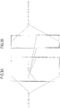
- FIGS. 3A, 3B Two format variants of the present OSB panels are shown.
- an OSB plate with a length of 2500 mm and a width between 625-2800 mm is provided, which is provided at the longitudinal edges with the inventive profile of simple fold and glue hose.
- the front sides are provided in this format with a blunt impact (ie without edge processing).
- This OSB board format is used in particular as a so-called storey height.
- OSB boards are provided with a length of 2500 mm and a width of 675 mm, which is also provided at the longitudinal edges with the inventive profile of simple fold and glue hose.
- the end faces are designed in this format with known tongue and groove profiling, which also here preferably a rounding of the plate edges is provided.
- This OSB board format is used in particular as a laying plate.
- An OSB / 3 or OSB / 4 with a thickness between 9 to 40 mm, a length of 2500 mm and a width of 1280 mm is initially in a laminating with a paper carton provided with a thickness of 0.8-2.6. It should be understood that these formats are merely exemplary in nature and are not to be considered as limiting.
- the folds each have a width of 30 mm and a depth of 10 mm.
- the plate edges are rounded off. This is done in tongue and groove machines, which are equipped with tools for this or that profiling by retooling accordingly.
- a rounded groove (radius 3 mm) is introduced as a loading channel for a glue cord by means of a milling cutter.
- the polyamide film used for the glue hose has a thickness of 70-80 ⁇ m.
- the glue hose is filled with a PVAC glue with a solids content of 65% by weight. Between the segments there is a seal with a width of about 2 mm.
Landscapes
- Engineering & Computer Science (AREA)
- Architecture (AREA)
- Civil Engineering (AREA)
- Structural Engineering (AREA)
- Life Sciences & Earth Sciences (AREA)
- Wood Science & Technology (AREA)
- Mechanical Engineering (AREA)
- Finishing Walls (AREA)
- Cartons (AREA)
Abstract
Description
- Die vorliegende Erfindung betrifft eine modifizierte OSB Platte mit einem neuen Verbindungsprofil und deren Verwendung zur Wand- und/oder Deckenverkleidung.
- Grobspanplatten, auch OSB-Platten (Oriented Strand Board) genannt, sind Holzwerkstoffplatten, die aus langen schlanken Spänen (Strands) hergestellt werden. OSB-Platten werden zunehmend im Holz- und Fertighausbau eingesetzt, da OSB-Platten leicht sind und trotzdem die an Bauplatten gesetzten statischen Anforderungen erfüllen. So werden OSB-Platten als Bauplatten und als Wand- oder Dachbeplankung oder auch im Fußbodenbereich eingesetzt.
- Die in den verschiedensten Bereichen im Innenausbau eingesetzten OSB-Platten, müssen beim Verlegen miteinander fixiert werden. Eine Fixierung wird zum Beispiel durch die Ausbildung von einer entlang einer Längs- und/oder Querkante vorgesehenen Nut und einer an der gegenüberliegenden Längs- und/oder Querkante ausgebildeten Feder bewirkt, wobei die Feder in die Nut eingreift (sog. Nut-Feder-Verbindung).
- Bei diesen sogenannten Nut-Feder-Verbindungen handelt es sich um Verbindungen, die eine formschlüssige Verriegelung zum Beispiel von Bodenpaneelen bei einer schwimmenden Verlegung ermöglichen. Nut-Feder-Verbindungen greifen ineinander und lassen sich daher nur ineinanderschieben bzw. stecken. Hierdurch können in horizontaler Richtung Haltekräfte von einer Bodenplatte in eine damit verbundene benachbarte Bodenplatte übertragen werden und Unebenheiten im Boden ausgeglichen werden.
- Eine vertikale Verlegung von OSB Platten zum Beispiel als Wandpaneele mit einer Nut-Feder-Verbindung ist allerdings für den Anwender mit einigem Kraftaufwand verbunden und somit unpraktisch.
- Aus der
WO 2017/013221 A1 sind Bodenpaneele bekannt, die im Wesentlichen einen modifizierten Falz aufweisen, der bei einer Verklebung eine gute Verbindung der Paneel Kanten ermöglicht und sich somit auch für eine schwimmende Verlegung für Fußböden eignet. Der hier vorgeschlagene Ansatz verwendet Paneel Kanten mit Kantenbrechungen, die eine Hinterschneidung der Paneele hervorrufen. Jedoch wären Paneele mit diesem Profileinsatz für eine Beplankung eines Ständerwerkes zur Herstellung einer Wand nicht geeignet, da auch hier ein höherer Kraftaufwand seitens der verlegenen Person notwendig ist. - In der
DE 20 2014 105 181 U1 werden Wandplatten für den Trockenbau aus einem Holzwerkstoff verwendet, die an den Schmalseiten einen Stufenfalz aufweisen. - Zusätzlich ist es zur Vermeidung eines Auseinandertriftens der so miteinander verbundenen Platten und einer damit einhergehenden Spaltbildung an der Verbindungsstelle notwendig, die einzelnen OSB-Platten entweder zusätzlich miteinander zu verleimen oder durch Schrauben auf Balken oder Holzrahmenkonstruktionen zu fixieren. Dies ist insbesondere bei vertikalen Anwendungen erforderlich.
- Wie erwähnt können OSB Platten als Bauplatten, insbesondere in der Herstellung von Fertighäusern verwendet werden. Zum Beispiel wird für den Fall, dass OSB Platten für Wandkonstruktionen verwendet werden, die Wand aus einem soliden Holzrahmen mit entsprechenden Balken hergestellt, die von beiden Seiten mit OSB Platten abgedeckt sind. Der Zwischenraum zwischen den Rahmenelementen wird in geeigneter Weise isoliert.
- Typischerweise wird die Seite der Konstruktionswand, die zur Innenseite des Hauses oder Gebäudes zeigt, mit einer Gipsbauplatte abgedeckt. Gipsbauplatten sind normalerweise jedoch sehr schwer (Dichte von über 1200 kg/m3) und erfordern Kenntnis und einigen Aufwand bei Anbringung. Die Oberfläche erfordert zudem das Aufbringen einer Gipsschicht und Spezialwerkzeuge sind für Schneidzwecke erforderlich.
- Entsprechend besteht ein Bedürfnis nach alternativen bzw. dem Verzicht zu Gipsbauplatten für den Innenausbau von Gebäuden, welche in einfacher Weise herstellbar und miteinander verlegbar und direkt beschichtbar sind, und die Nachteile der konventionell verwendeten Gipsbauplatten überkommen.
- Der vorliegenden Erfindung liegt daher die technische Aufgabe zugrunde, die angesprochenen Nachteile der bekannten Systeme zu beheben, und ein einfaches, aber effizientes Verfahren bereitzustellen, das dem Benutzer bzw. Verarbeiter eine einfache Verlegung von OSB Platten als Wand- oder Deckenpaneele ohne zusätzliche Kosten ermöglicht. Zudem soll die bereitgestellten OSB Platten eine Alternative zu den konventionell verwendeten Gipsbauplatten darstellen.
- Die gestellte Aufgabe wird erfindungsgemäß durch eine OSB-Platte mit den Merkmalen des Anspruchs 1 gelöst.
- Demnach wird eine OSB- Platte mit mindestens zwei sich einander gegenüberliegenden Plattenkanten, insbesondere zwei sich gegenüberliegenden Längskanten, bereitgestellt, wobei jede der zwei sich gegenüberliegenden Plattenkanten einen einfachen Falz aufweist, wobei der Falz in der einen Plattenkante komplementär zu dem Falz in der gegenüberliegenden Plattenkante ist.
- Erfindungsgemäß ist in bzw. auf mindestens einem der sich gegenüberliegende Falze mindestens ein Leimschlauch (oder eine Leimschnur) vorgesehen. Bevorzugter Weise ist der mindestens eine Leimschlauch in mindestens einer in dem Falz vorgesehenen Nut angeordnet. Die Nut kann auch als Einlegekanal für den Leimschlauch bezeichnet werden.
- Im Sinne der vorliegenden Erfindung ist unter einem Falz ein Absatz oder Fuge in einer Platte (oder allgemein in einem Körper) zu verstehen. Der Falz (bzw. Absatz) ist jeweils am Rand bzw. an der Kante der OSB Platte vorgesehen und ermöglicht eine flächige Aneinanderreihung der OSB Platten. Insbesondere bilden die an den gegenüberliegen Plattenkanten vorgesehenen, komplementären Falze im verbundenen Zustand miteinander eine stufenförmige Verbindung.
- Ein einfacher Falz kann auch so beschrieben werden, dass in die Plattenkante ein gerader Absatz mit einer vorbestimmten Tiefe und Breite z.B. mittels Fräsen eingebracht wird. Entsprechend wird ein Absatz (oder Falz) gebildet, bei dem die Kante in einem Bereich der Platte mit einer vorbestimmten Breite hervorsteht und in einem anderen Bereich mit einer vorbestimmten Tiefe zurücksteht.
- Im Falle von komplementären Falzen (oder Absätzen) steht der Falz in einer Plattenkante z.B. in einem unteren Bereich der Plattenkante hervor und in einem oberen Bereich zurück, wobei die gegenüberliegende Plattenkante einen komplementären Falz aufweist, der im oberen Bereich der Plattenkante hervorsteht und im unteren Bereich zurücksteht.
- Beim Verlegen der OSB-Platten ermöglicht der erfindungsgemäße Falz ein einfaches Ablegen der OSB-Platten aufeinander. Aus diesem Grunde sind die erfindungsgemäßen OSB-Platten auch gut für eine Beplankung eines Ständerwerkes zur Herstellung einer Wand geeignet, im Gegensatz zu den Nut-Feder-Verbindungen, die sich nur ineinanderschieben bzw. stecken lassen.
- In einer Ausführungsform der vorliegenden OSB-Platte beträgt die Breite des Falzes in den sich gegenüberliegenden Plattenkanten jeweils zwischen 20 und 40 mm, bevorzugt zwischen 25 und 35 mm, insbesondere bevorzugt 30 mm.
- Die Falzbreite ist in den sich gegenüberliegenden Plattenkanten bevorzugt gleich. Es ist aber generell auch vorstellbar, dass die Falzbreite in den gegenüberliegenden Plattenkanten unterschiedlich ist.
- In einer weiteren Ausführungsform der vorliegenden OSB-Platte entspricht die Tiefe des Falzes mindestens einem Drittel, bevorzugt mindestens der Hälfte der Dicke der OSB-Platte entspricht. Dabei kann die Dicke der OSB-Platte zwischen 9 und 50 mm, bevorzugt zwischen 10 und 25 mm, insbesondere bei 18 mm liegen. Entsprechend beträgt die Tiefe des Falzes für den Fall, dass die Falztiefe der Hälfte der Plattendicke entspricht, zwischen 4,5 und 25 mm, bevorzugt zwischen 5 und 12,5 mm, insbesondere 9 mm.
- Der Falz wird mittels geeigneter Werkzeuge in die Platte eingebracht. Insbesondere erfolgt ein Fräsen und Abtragen der Holzplatte an den Kanten.
- In einer Variante ist der Leimschlauch auf dem Falz durch Klebepunkte verliersicher befestigt. Die Öffnung des Leimschlauchs erfolgt durch das Zusammenpressen der Falzverbindung, insbesondere durch den Druck auf Grund zusätzlicher mechanischer Verbindungsmittel, wie Nägel, Klammern oder Schrauben. Die mechanischen Verbindungsmittel pressen die Falze zusammen und reichen auch bis in dahinter befindliches Ständerwerk. Der Leimschlauch kann perforiert ausgeführt sein und bildet in diesen Bereichen definierter Schwächung eine Sollbruchstelle für leichteres Öffnen aus.
- Wie oben bereits ausgeführt, kann der Leimschlauch auch in eine Nut eingelegt sein und optional durch Klebepunkte verliersicher in der Nut befestigt sein.
- In einer bevorzugten Ausführungsform ist diese Nut lediglich in einem Falz, insbesondere in dem unteren Falz vorgesehen; d.h. in der Falz die in der OSB-Platte vor dem Verlegen bzw. Verkleben für den Anwender in der Draufsicht erkennbar ist.
- Es ist vorgesehen, dass die mindestens eine Nut für den mindestens einen Leimschlauch entlang der gesamten Länge der Plattenkante verläuft. Der Leimschlauch bzw. der im Leimschlauch enthaltende Leim dient zur Verklebung der Falze als Verbindungsstellen der OSB-Platten und zur Luftdichtheit an der Verbindung der jeweiligen OSB-Platten.
- Es ist weiterhin vorgesehen, dass die mindestens eine Nut für den mindestens einen Leimschlauch mit einem Radius zwischen 1 und 5 mm, bevorzugt zwischen 2 und 4 mm, insbesondere bevorzugt 3 mm in die Oberfläche der Falz eingebracht ist. Dabei wird die Nut in die Oberfläche des Falzes eingefräst oder eingesägt, z.B. mittels eines Fräsers oder eines Sägeblattes mit der Form der einzubringenden Nut. Die Nut kann eine halbrunde Form oder auch eine flachere, ovale Form aufweisen. Im Falle einer ovalen Form der Nut wäre der Querschnitt des Leimschlauches ebenfalls oval ausgeführt.
- Es wäre aber auch vorstellbar, dass eine Nut jeweils in sich gegenüberliegenden Falzen vorgesehen ist; d.h. sowohl in dem unteren als auch in dem komplementären oberen Falz.
- Ist hingegen lediglich eine Nut in dem unteren Falz vorgesehen, kann der obere Falz glatt ausgeführt sein. Dies vereinfacht die Herstellung.
- In einer weiteren Ausführungsform wäre es aber auch denkbar, dass auf dem oberen Falz ein erhabener Steg mit alternierenden symmetrischen Erhebungen vorgesehen ist, der komplementär zu der Nut im unteren Falz angeordnet ist. Die alternierenden symmetrischen Erhebungen bewirken bei einem Zusammenbringen bzw. Aufeinanderlegen von sich gegenüberliegenden Falzen aufgrund der dabei angewendeten Kräfte beziehungsweise des aufgebrachten Drucks ein Öffnen bzw. eine Zerstörung des in der Nut eingelegten Leimschlauches. Der Klebstoff wird freigesetzt und verteilt sich in dem Bereich des Falzes. In einer bevorzugten Ausführungsform weisen die Erhebungen beziehungsweise Erhöhungen auf dem mindestens einen Falz eine jeweils von der Holzwerkstoffplatte wegweisende spitzförmig zulaufende Geometrie auf. Dabei sind die Seiten der jeweiligen Erhebung bevorzugter Weise jeweils gleich lang. Die Höhe und Winkelabmessungen zwischen den Seiten der bevorzugt spitzförmig zu laufenden Erhebungen können je nach Plattenstärke und Falzgeometrie variiert werden. So können die Winkelabmessungen des inneren Winkels der spitzförmig zu laufenden Erhebung variieren, wobei ein kleiner innerer Winkel eine spitzere Erhebung bedeutet. Die Winkelgröße sollte abhängig sein von dem für dem Leimschlauch verwendeten Material und die für die Öffnung des Leimschlauches aufzubringende Kraft bzw. Druck Wird zum Beispiel ein festeres Material für den Leimschlauch verwendet, so sollte die Erhebung relativ spitzwinklig ausfallen, um ein Öffnen des Leimschlauches zu ermöglichen. Im umgekehrten Falle kann bei der Verwendung eines weicheren Materials für den Leimschlauch eine weniger spitze Erhebung ausreichend zum Öffnen des Leimschlauches sein. Die Erhebungen können eine Höhe von 1 bis 5 mm, bevorzugt 2 bis 4 mm aufweisen.
- Es ist insbesondere bevorzugt, wenn der mindestens eine Leimschlauch als durchgängiger Schlauch, zum Beispiel in Form eines extrudierten Schlauches, ausgebildet ist, der den Leim bzw. Klebstoff enthält.
- In einer anderen Ausführungsform der vorliegenden OSB-Platte ist der mindestens eine Leimschlauch entlang seiner Länge in einzelne Segmente bzw. Kammern unterteilt. Die Segmente bzw. Kammern sind bevorzugt von gleicher Größe, das heißt weisen gleiche Volumina zur Aufnahme einer gleichen Menge an Klebstoff auf. Die Segmente bzw. Kammern können durch Schweißnähte oder sogenannte Siegelstellen z.B. mit einer Breite zwischen 1 und 3 mm, bevorzugt 2 mm gebildet werden. Auch ist eine Unterteilung des Schlauches in Segmente unter Verwendung von Perforationslinien möglich, wobei die Perforationslinien sich auf der Oberseite- und/oder der Unterseite des Leimschlauches befinden können
- In einer Ausführungsform weist der Leimschlauch einen Durchmesser zwischen 3 und 10 mm, bevorzugt 5 und 9 mm auf. Die Länge eines einzelnen Segmentes des Leimschlauches kann zwischen 100 und 200 mm, bevorzugt zwischen 130 und 180 mm, insbesondere bevorzugt zwischen 150 und 170 mm betragen.
- Die Verwendung eines Leimschlauches mit durch Siegelstellen voneinander getrennten Segmenten weist verschiedene Vorteile auf. So tritt bei Beschädigungen des Leimschlauches) während des Transports, der Lagerung oder der Verarbeitung bei einer Segmentierung lediglich der Klebstoff bzw. der Leim aus dem beschädigten Segment aus und entsprechend wird ein Leerlaufen des gesamten Leimschlauches verhindert. Des Weiteren ermöglicht eine Segmentierung des Leimschlauches auch die Verarbeitung von unterschiedlichen Formaten an Holzwerkstoffplatten, da diese im Format nur ein vielfaches der Einzelsegmentlänge der Leimschlauchsegmente entsprechen müssen (ein Trennen des Leimschlauches in der Siegelstelle ist problemlos möglich).
- In einer weiteren Ausführungsform der vorliegen OSB-Platte besteht der Leimschlauch aus einem Kunststoffmaterial. Das Kunststoffmaterial sollte dabei so ausgewählt sein, dass es über eine bestimmte Festigkeit verfügt, so dass ein Aufreißen des Schlauches während der Herstellung und dem Transport der OSB-Platte vermieden wird, jedoch beim Verlegen der OSB-Platten geöffnet werden kann. Besonders bevorzugtes Kunststoffmaterial, das hier zum Einsatz kommt, ist Polyethylenterephthalat (PET), Polyamid (PA) und/oder Polyethylen (PE) oder eine Mischung davon. Es können aber auch beliebig andere Folien oder Verbundfolien zur Herstellung des Leimschlauches verwendet werden. Im Falle der Verwendung einer Polyamidfolie als Schlauchmaterial weist diese eine Dicke bzw. Stärke zwischen 50 und 100 µm, bevorzugt zwischen 70 und 80 µm auf.
- Der vorliegend zum Einsatz kommende Klebstoff ist ausgewählt aus der Gruppe enthaltend Polyvinyle und Acrylate. Als besonders vorteilhaft ist die Verwendung von wasserhaltigen Klebestoffformulierungen wie Polyvinylacetat (PVAC) oder Ethylenvinylacetat (EVA). Selbstverständlich können auch andere Leime mit Wasser als Lösemittel eingesetzt werden. In einer Ausführungsform kann als Klebstoff ein PVAC Leim mit einem Feststoffgehalt zwischen 50 und 80 Gew.%, bevorzugt zwischen 60 und 79 Gew.%, insbesondere bevorzugt von 65 Gew.% verwendet werden.
- In einer weitergehenden Ausführungsform der vorliegenden OSB-Platte, die als Platte natürlicherweise eine Oberseite und eine Unterseite aufweist, ist vorgesehen, dass die Plattenkanten jeweils an der Plattenoberseite eine Abrundung mit einem Radius zwischen 3 und 10 mm, bevorzugt zwischen 5 und 8 mm, insbesondere bevorzugt zwischen 6 und 7 mm aufweist; d.h. die Plattenkanten weisen an dem hervorstehenden und/oder dem zurückstehenden Bereich der Falz eine entsprechende Abrundung auf. Bei Zusammenfügen der Platten bilden die Abrundungen im verbundenen Zustand miteinander eine Fuge der Oberfläche, die verspachtelt werden kann.
- Es ist ebenfalls in einer Variante vorgesehen, dass die im Bereich der Falzverbindung von zwei OSB-Platten eine mechanische Verbindung bzw. Befestigung vorgesehen, die bevorzugt bis in den Ständer des Ständerwerkes reicht, auf welchen die OSB-Platte befestigt wird. Eine solche mechanische Befestigung kann mit Nägeln, Schrauben oder Klammern erfolgen. Eine Klammerung bzw. Klammer besteht aus zwei Nägeln, die miteinander verbunden sind. Das Eintreiben der Klammer in die Falzverbindung erfolgt mit einer pneumatischen Klammerpistole.
- Das erfindungsgemäß in einer OSB-Platte vorgesehene Profil weist eine Vielzahl von Vorteilen auf: So wird durch die Art der Überdeckung und Verbindungsmöglichkeit eine statische Wirkung erreicht. Durch die Abrundung an der Profiloberfläche kann der Plattenstoß verspachtelt werden. Durch die Überblattung 50/50 kann die Platte am Stoß über beide Lagen geklammert werden (mind. 30% Einsparung der Klammern). Durch die Nut bzw. Einlegekanal für einen Leimschlauch in das Falzprofil wird eine selbstleimende und luftdichte Verbindung zwischen den OSB-Platten an der Verbindungsstelle erreicht. Es wird ein kraftschlüssiger Verbund für geschlossene Oberflächen bereitgestellt. Die OSB-Platten können mittels Schrauben oder Klammern an dafür vorgesehenen Rahmen befestigt werden, so dass geschoßhohe Formate realisiert werden können.
- In einer weiteren, bevorzugten Ausführungsform der vorliegenden OSB-Platte ist die Oberfläche der OSB-Platte mit mindestens einer Lage eines Papieres versehen.
- In einer Variante kann vorgesehen sein, dass eine erste Papierlage mit mindestens einem Harz, insbesondere einen Formaldehyd-Harz imprägniert ist. Bei dieser ersten Papierlage handelt es sich insbesondere um Papierlage, die direkt auf der OSB-Oberfläche angeordnet ist. Bei dem Formaldehyd-Harz handelt es sich insbesondere im ein Melamin-Formaldehyd-Harz, Urea-Formaldehyd-Harz, Melamin-Urea-Formaldehyd-Harz.
- Das für die erste Papierlage verwendete Papier weist ein Flächengewicht zwischen 30 und 200 g/m2, bevorzugt zwischen 50 und 150 g/m2, insbesondere bevorzugt zwischen 80 und 120 g/m2 auf.
- In einer anderen Variante ist eine zweite Papierlage auf der ersten Papierlage vorgesehen, wobei zweite Papierlage bevorzugt aus einem rohen (d.h. unbehandelten, nicht imprägnierten) Papier besteht. Das Flächengewicht des Rohpapiers der zweiten Papierlage liegt zwischen 30 und 300 g/m2, bevorzugt zwischen 50 und 250 g/m2, insbesondere bevorzugt zwischen 100 und 120 g/m2. Das Anordnen eines Rohpapiers als äußerste Schicht auf einer OSB-Platte ermöglicht die Bereitstellung eines Substrates, auf welchem direkt Innenwandfarbe, Spachtelmasse oder Klebstoff für Tapeten aufgebracht werden kann.
- Es ist auch möglich, hydrophobe Komponenten als Schutz gegen Klimaeinflüsse oder einen dünnen Metallfilm zur Wärmereflexion auf die zweite Papierlage aufzubringen.
- In einer besonders bevorzugten Ausführungsform ist die mindestens eine Papierlage in Form eines Kartonagepapiers ausgeführt.
- Das Kartonagepapier weist eine Dicke zwischen 0,5 und 5 mm, bevorzugt zwischen 1 und 4 mm, insbesondere bevorzugt zwischen 2 und 3 mm auf. In einer Variante kann die Dicke des Kartonagepapiers zwischen 0,8 und 2,6 mm, z.B. bei 1, 5 mm liegen.
- Das Kartonagepapier wird bevorzugt vor der Einbringung des Falzprofils in die Plattenkanten auf die Oberfläche der OSB-Platte aufkaschiert. Beim Kaschieren von dickere Pappen bzw. Papierkartonagen wird ein Klebstrich auf die Oberseite der OSB aufgebracht und anschließend die Kartonage auf der Oberseite abgerollt. Sowohl OSB-Platte als auch die Kartonage bewegen sich durch die Kaschieranlage. Zwischen den Walzen wirkt zusätzlich ein linienförmiger Druck, durch den die Verbindung zwischen OSB-Platte und Kartonage unterstützt wird.
- Es ist auch generell möglich und vorstellbar, dass das mindestens eine Kartonagepapier mit der OSB-Platte in einer Kurztaktpresse verpresst wird. In diesem Falle wird auf die Oberfläche der OSB-Platte zunächst ein beharztes Papier aufgebracht, auf welches das Kartonagepapier gelegt wird. Das Papier kann z.B. mit einem oder mehreren Harzen aus der Gruppe umfassend Melamin-Formaldehyd-Harz, Harnstoff-Melamin-Formaldehyd-Harz, Phenol-Melamin-Formaldehyd-Harz getränkt bzw. imprägniert sein. Durch das anschließende Verpressen z.B. in einer Kurztaktpresse bei erhöhten Temperaturen kommt es zu einem Anschmelzen des Harzes im beharzten Papier, welches als Adhäsionsmittel bzw. Klebstoff zwischen OSB-Oberfläche und Kartonagepapier wirkt.
- Auch ist es möglich, dass mindestens ein Kartonagepapier direkt beim Herstellungsprozess der OSB-Platte auf die selbige aufzubringen. Dabei wird nach dem Aufbringen der OSB-Strands auf ein Transportband in der Reihenfolge untere Deckschicht - mittlere Deckschicht - obere Deckschicht das Kartonagepapier als Auflage online auf der oberen Deckschicht abgelegt und der gesamte Schichtaufbau unter Druck- und Temperatureinfluss verpresst.
- Die Beschichtung bzw. Kaschierung von OSB-Oberflächen mit Kartonagepapier weist eine Vielzahl von Vorteilen auf: Durch einseitiges Aufbringen auf eine Plattenoberfläche wird eine glatte beschichtbare Oberfläche mit den Eigenschaften wie eine Gipsbauplatte oder Gipsfaserplatte bereitgestellt, die über die zusätzlichen Eigenschaften einer Holzplatte, wie sehr gute Befestigungsmöglichkeiten (z.B. mittels Schrauben oder Klammern) oder Spezialdübel verfügt. Eine derart modifizierte OSB-Platte kann als Finish-Oberfläche eingesetzt werden. Auch sind die modifizierten OSB-Platten statisch und luftdicht einsetzbar.
- Die vorliegende modifizierte OSB-Platte kommt insbesondere zur Herstellung von Wand- und/oder Deckenverkleidung zum Einsatz.
- Hierfür kann die vorliegende OSB-Platte in verschiedenen Formaten verwendet werden.
- In einem ersten Format werden OSB-Platten mit einer Länge zwischen 2000-5000 mm, bevorzugt 2500 mm, und einer Breite zwischen 600 -2800 mm, bevorzugt zwischen 625-2500 mm, und an den Längskanten mit dem erfindungsgemäßen Profil aus einfacher Falz und Leimschlauch bereitgestellt. Die Stirnseiten sind in diesem Format mit einem stumpfen Stoß (d.h. ohne Kantenbearbeitung) versehen. Dieses OSB-Plattenformat kommt insbesondere in Geschosshöhe zum Einsatz, wobei die Breite der Heißpresse und damit die maximale Breite der Platte der Höhe eines Geschosses (Etage) beim Bauen entsprechen. Somit deckt die Breite der OSB eine ganze Geschosshöhe (Etagenhöhe) ab. Dies erfolgt meist in solchen Bauten, in denen die tragende Struktur weitgehend durch ein Holzständerwerk realisiert wird - dieses Ständerwerk wird dann statisch aussteifend mit den hier in Rede stehenden OSB beplankt. Daher sind die OSB geschosshoch, wobei entlang der Geschoßhöhe die OSB-Platten einen stumpfen Stoß (d.h. ohne Falz) aufweisen. Die Falze sind dann an den OS-Platten vertikal zur Geschoßhöhe vorgesehen.
- In einem zweiten Format werden OSB-Platten mit einer Länge zwischen 2000-3000 mm, bevorzugt 2500 mm, und einer Breite zwischen 500-1000 mm, bevorzugt 625 mm, und an den Längskanten mit dem erfindungsgemäßen Profil aus einfacher Falz und Leimschlauch bereitgestellt. Die Stirnseiten sind in diesem Format mit bekannter Nut- und Federprofilierung ausgeführt, wobei auch hier bevorzugt eine Abrundung der Plattenkanten vorgesehen ist. Dieses OSB-Plattenformat kommt insbesondere als Verlegeplatte zum Einsatz.
- Die vorliegende OSB-Platte kommt ebenfalls in einem Verfahren zum Verbinden (oder Verlegen) von zwei oder mehreren OSB-Platten mit den folgenden Merkmalen zum Einsatz. In diesem Verfahren wird eine erste OSB-Platte mit den obigen Merkmalen mit einer anderen (zweiten) OSB-Platte mit den obigen Merkmalen verbunden, wobei der Falz der einen ersten OSB-Platte auf dem komplementären Falz der weiteren zweiten OSB-Platte gelegt und zusammen gepresst wird, wobei durch das Zusammenpressen der beiden OSB-Platten der in der Falz, und hier insbesondere in der Nut, vorgesehene Leimschlauch geöffnet und der Leim aus dem Leimschlauch freigesetzt wird.
- Durch das Verbinden bzw. Verlegen der OSB-Platten kommt es zur Ausbildung einer Fuge zwischen den verlegten Platten, die anschließend in bekannter Weise verspachtelt werden kann.
- Im Anschluss an das Verspachteln kann die Oberfläche in Analogie zu den konventionellen Gipsbauplatten weiter bearbeitet werden, z.B. Streichen, Tapezieren etc..
- Die Erfindung wird nachfolgend unter Bezugnahme auf die Figuren der Zeichnungen Ausführungsbeispielen näher erläutert. Es zeigen:
- Figur 1
- eine schematische Querschnittsansicht einer OSB-Platte gemäß einer ersten Ausführungsform der vorliegenden Erfindung;
- Figur 2
- eine seitliche Draufsicht auf die in
Figur 1 gezeigten Ansicht einer erfindungsgemäßen OSB-Platte, - Figur 3A
- eine Ansicht eines ersten Verlegeformats der erfindungsgemäßen OSB-Platte, und
- Figur 3B
- eine Ansicht eines zweiten Verlegeformats der erfindungsgemäßen OSB-Platte.
-
Figur 1 zeigt eine schematische Querschnittsansicht auf eine OSB-Platte 1 mit einer Breite zwischen 625-2800 mm, die an sich gegenüberliegenden Plattenkanten 2, 3 jeweils mit einem einfachen Falz 2a, 3a versehen sind, wobei beide Falze 2a, 3a komplementär zueinander ausgebildet sind. - Entsprechend steht der Falz 2a in der Plattenkante 2 in einem unteren Bereich der Plattenkante 2 hervor und in einem oberen Bereich zurück, wobei im Falle des komplementären Falzes 3a der obere Bereich der Plattenkante 3 hervorsteht und der untere Bereich zurücksteht.
- Die Breite der beiden Falze 2a, 3a beträgt jeweils 30 mm. Die Tiefe der Falze entspricht jeweils Hälfte der Dicke der OSB-Platte; d.h. bei einer Plattendicke zwischen 9 und 40 mm beträgt die Falztiefe 4,5 bis 20 mm.
- In die Oberfläche des Falzes 2a ist eine abgerundete Nut 2b als Einlegekanal für einen Leimschlauch bzw. Leimschnur vorgesehen. Die abgerundete Nut 2b weist einen Radius von 3 mm auf.
- Auf die Oberseite der OSB-Platte 1 ist eine Lage eines Kartonagepapiers 4 mit einer Dicke zwischen 0,8-2,6 mm aufkaschiert.
- Die Plattenkanten 2, 3 inklusive des Kartonagepapiers 4 sind zusätzlich abgerundet (Radius ca. 6 mm), wobei die Plattenkante 2 an dem zurückstehenden Bereich der Falz 2a die Abrundung 2c und die Plattenkante 3 an dem hervorstehenden Bereich der Falz 3a die entsprechende Abrundung 3c aufweisen. Bei Zusammenfügen der Platten bilden die Abrundungen im verbundenen Zustand miteinander eine Fuge der Oberfläche, die verspachtelt werden kann.
-
Figur 2 zeigt die Ausführungsform derFigur 1 in einer seitlichen, perspektivischen Draufsicht. Hierfür kann die vorliegende OSB-Platte in verschiedenen Formaten verwendet werden. - In
Figuren 3A, 3B sind zwei Formatvarianten der vorliegenden OSB Platten gezeigt. - Gemäß einem ersten Format (
Fig. 3A ) wird eine OSB-Platte mit einer Länge von 2500 mm und einer Breite zwischen 625-2800 mm bereitgestellt, die an den Längskanten mit dem erfindungsgemäßen Profil aus einfacher Falz und Leimschlauch versehen ist. Die Stirnseiten sind in diesem Format mit einem stumpfen Stoß (d.h. ohne Kantenbearbeitung) versehen. Dieses OSB-Plattenformat kommt insbesondere als sog. Geschosshöhe zum Einsatz. - Gemäß einem zweiten Format (
Fig. 3B ) werden OSB-Platten mit einer Länge von 2500 mm und einer Breite von 675 mm bereitgestellt, die ebenfalls an den Längskanten mit dem erfindungsgemäßen Profil aus einfacher Falz und Leimschlauch versehen ist. Die Stirnseiten sind in diesem Format mit bekannter Nut- und Federprofilierung ausgeführt, wobei auch hier bevorzugt eine Abrundung der Plattenkanten vorgesehen ist. Dieses OSB-Plattenformat kommt insbesondere als Verlegeplatte zum Einsatz. - Eine OSB/3 oder OSB/4 mit einer Dicke zwischen 9 bis 40 mm, einer Länge von 2500 mm und einer Breite von 1280 mm wird zunächst in einer Kaschieranlage mit einer Papierkartonage mit einer Dicke von 0,8-2,6 versehen. Es sei darauf hingewiesen, dass diese Formate lediglich beispielhafter Natur sind, und nicht als begrenzend anzusehen sind.
- Anschließend wird in einer Fräsanlage entlang der beiden Längskanten ein einfacher Falz eingefügt. Die Falze haben jeweils eine Breite von 30 mm und eine Tiefe von 10 mm.
- Die Plattenkanten werden abgerundet. Dies erfolgt in Nut- und Feder-Anlagen, die entsprechend mit Werkzeugen für diese oder jene Profilierung durch Umrüsten ausgestattet werden.
- In den unteren Falz wird eine abgerundete Nut (Radius 3 mm) als Einlegekanal für eine Leimschnur mittels eines Fräsers eingebracht.
- In die Nut ist ein Leimschlauch mit einem Durchmesser von 9 mm eingelegt, der aus abgeteilten Einzelsegmenten mit einer Länge von ca. 169 mm bestehen. Die für den Leimschlauch verwendete Polyamidfolie hat eine Stärke von 70 - 80 µm. Der Leimschlauch ist mit einem PVAC-Leim mit einem Feststoffgehalt von 65 Gew. % gefüllt. Zwischen den Segmenten befindet sich eine Siegelung mit einer Breite von ca. 2 mm.
Claims (13)
- OSB- Platte mit mindestens zwei einander gegenüberliegenden Plattenkanten, insbesondere zwei sich gegenüberliegenden Längskanten,wobei jede der zwei sich gegenüberliegenden Plattenkanten einen einfachen Falz aufweist, wobei der Falz in der einen Plattenkante komplementär zu dem Falz in der gegenüberliegenden Plattenkante ist,
dadurch gekennzeichnet, dassin mindestens einem der sich gegenüberliegende Falze jeweils mindestens ein Leimschlauch, insbesondere in mindestens einer Nut, vorgesehen ist. - OSB-Platte nach Anspruch 1, dadurch gekennzeichnet, dass die Breite des Falzes in den sich gegenüberliegenden Plattenkanten jeweils zwischen 20 und 40 mm, bevorzugt zwischen 25 und 35 mm, insbesondere bevorzugt 30 mm beträgt.
- OSB-Platte nach einem der vorhergehenden Ansprüche, dadurch gekennzeichnet, dass die Tiefe des Falzes mindestens einem Drittel, bevorzugt mindestens der Hälfte der Dicke der OSB-Platte entspricht.
- OSB-Platte nach einem der vorhergehenden Ansprüche, dadurch gekennzeichnet, dass die mindestens eine Nut für den mindestens einen Leimschlauch entlang der gesamten Länge der Plattenkante verläuft.
- OSB-Platte nach einem der vorhergehenden Ansprüche, dadurch gekennzeichnet, dass die mindestens eine Nut für den mindestens einen Leimschlauch mit einem Radius zwischen 1 und 5 mm, bevorzugt zwischen 2 und 4 mm, insbesondere bevorzugt 3 mm in die Oberfläche der Falz eingebracht ist.
- OSB-Platte nach einem der vorhergehenden Ansprüche, dadurch gekennzeichnet, dass der mindestens eine Leimschlauch ein durchgängiger Schlauch ist oder ein Schlauch ist, der entlang seiner Länge in einzelne Segmente unterteilt ist.
- OSB-Platte nach einem der vorhergehenden Ansprüche, dadurch gekennzeichnet, dass die Plattenkanten jeweils an der Plattenoberseite eine Abrundung mit einem Radius zwischen 3 und 10 mm, bevorzugt zwischen 5 und 8 mm, insbesondere bevorzugt zwischen 6 und 7 mm aufweist.
- OSB-Platte nach einem der vorhergehenden Ansprüche, dadurch gekennzeichnet, dass in den komplementären sich überlagernden Falzen der Plattenkanten eine Klammerung erfolgen kann.
- OSB-Platte nach einem der vorhergehenden Ansprüche, dadurch gekennzeichnet, dass die Plattenoberseite der OSB-Platte mit mindestens einer Lage eines Kartonagepapiers versehen ist.
- OSB-Platte nach Anspruch 9, dadurch gekennzeichnet, dass das Kartonagepapier eine Dicke zwischen 0,5 und 5 mm, bevorzugt zwischen 1 und 4 mm, insbesondere bevorzugt zwischen 2 und 3 mm aufweist.
- Verwendung einer OSB-Platte nach einem der vorhergehenden Ansprüche zur Herstellung von Wand- und/oder Deckenverkleidungen.
- Verfahren zum Verbinden (Verlegen) einer ersten OSB-Platte nach einem der Ansprüche 1 - 10 mit einer weiteren zweiten OSB-Platte nach einem der Ansprüche 1 - 10, dadurch gekennzeichnet, dass die Falz der einen ersten OSB-Platte auf die komplementäre Falz der weiteren zweiten OSB-Platte gelegt wird und zusammen gepresst wird, wobei durch das Zusammenpressen der beiden OSB-Platten der in der jeweiligen Nut der Falz vorgesehene Leimschlauch geöffnet wird und der Leim aus dem Leimschlauch freigesetzt wird.
- Verfahren nach Anspruch 12, dadurch gekennzeichnet, dass die durch das Verbinden der mindestens zwei OSB-Platten gebildete Fuge verspachtelt wird.
Priority Applications (14)
| Application Number | Priority Date | Filing Date | Title |
|---|---|---|---|
| PL17196384T PL3470599T3 (pl) | 2017-10-13 | 2017-10-13 | Płyta OSB i jej zastosowanie |
| EP19190530.6A EP3584387B1 (de) | 2017-10-13 | 2017-10-13 | Osb-platte und verwendung derselbigen |
| HUE19190530A HUE052362T2 (hu) | 2017-10-13 | 2017-10-13 | OSB-lap és annak alkalmazása |
| ES17196384T ES2752210T3 (es) | 2017-10-13 | 2017-10-13 | Tablero OSB y su utilización |
| PT171963846T PT3470599T (pt) | 2017-10-13 | 2017-10-13 | Placa osb e utilização da mesma |
| ES19190530T ES2821444T3 (es) | 2017-10-13 | 2017-10-13 | Placa OSB y utilización de la misma |
| PT191905306T PT3584387T (pt) | 2017-10-13 | 2017-10-13 | Placa osb e utilização da mesma |
| EP17196384.6A EP3470599B1 (de) | 2017-10-13 | 2017-10-13 | Osb-platte und verwendung derselbigen |
| HUE17196384A HUE047828T2 (hu) | 2017-10-13 | 2017-10-13 | OSB-lap és annak alkalmazása |
| RU2021138294A RU2777386C2 (ru) | 2017-10-13 | 2018-10-08 | Плита osb и ее применение |
| UAA201809996A UA125379C2 (uk) | 2017-10-13 | 2018-10-08 | Плита osb та її застосування |
| RU2018135275A RU2764092C2 (ru) | 2017-10-13 | 2018-10-08 | Плита osb и ее применение |
| US16/156,171 US10876300B2 (en) | 2017-10-13 | 2018-10-10 | OSB board and use of the same |
| CA3020609A CA3020609C (en) | 2017-10-13 | 2018-10-12 | Osb board and use of the same |
Applications Claiming Priority (1)
| Application Number | Priority Date | Filing Date | Title |
|---|---|---|---|
| EP17196384.6A EP3470599B1 (de) | 2017-10-13 | 2017-10-13 | Osb-platte und verwendung derselbigen |
Related Child Applications (2)
| Application Number | Title | Priority Date | Filing Date |
|---|---|---|---|
| EP19190530.6A Division EP3584387B1 (de) | 2017-10-13 | 2017-10-13 | Osb-platte und verwendung derselbigen |
| EP19190530.6A Division-Into EP3584387B1 (de) | 2017-10-13 | 2017-10-13 | Osb-platte und verwendung derselbigen |
Publications (2)
| Publication Number | Publication Date |
|---|---|
| EP3470599A1 true EP3470599A1 (de) | 2019-04-17 |
| EP3470599B1 EP3470599B1 (de) | 2019-09-11 |
Family
ID=60083866
Family Applications (2)
| Application Number | Title | Priority Date | Filing Date |
|---|---|---|---|
| EP17196384.6A Active EP3470599B1 (de) | 2017-10-13 | 2017-10-13 | Osb-platte und verwendung derselbigen |
| EP19190530.6A Active EP3584387B1 (de) | 2017-10-13 | 2017-10-13 | Osb-platte und verwendung derselbigen |
Family Applications After (1)
| Application Number | Title | Priority Date | Filing Date |
|---|---|---|---|
| EP19190530.6A Active EP3584387B1 (de) | 2017-10-13 | 2017-10-13 | Osb-platte und verwendung derselbigen |
Country Status (9)
| Country | Link |
|---|---|
| US (1) | US10876300B2 (de) |
| EP (2) | EP3470599B1 (de) |
| CA (1) | CA3020609C (de) |
| ES (2) | ES2752210T3 (de) |
| HU (2) | HUE052362T2 (de) |
| PL (1) | PL3470599T3 (de) |
| PT (2) | PT3584387T (de) |
| RU (1) | RU2764092C2 (de) |
| UA (1) | UA125379C2 (de) |
Families Citing this family (1)
| Publication number | Priority date | Publication date | Assignee | Title |
|---|---|---|---|---|
| EP4288621A1 (de) * | 2021-02-08 | 2023-12-13 | James Hardie Technology Limited | Klebplattenverbindung in einem gebäudeabschnitt |
Citations (6)
| Publication number | Priority date | Publication date | Assignee | Title |
|---|---|---|---|---|
| US2328051A (en) * | 1940-08-21 | 1943-08-31 | Minnesota & Ontario Paper Co | Wall construction |
| WO2004053257A1 (en) * | 2002-12-09 | 2004-06-24 | Pergo(Europe) Ab | A process for sealing of a joint |
| US20100236171A1 (en) * | 2009-03-18 | 2010-09-23 | Liu David C | Preinstalled glue system for floor |
| DE202014105181U1 (de) | 2014-10-29 | 2014-11-13 | Fritz Egger Gmbh & Co. Og | Wandplatte für den Trockenbau aus einem Holzwerkstoff sowie Wandaufbau |
| WO2016113721A1 (en) * | 2015-01-16 | 2016-07-21 | Flooring Industries Limited, Sarl | Floor panel for forming a floor covering |
| WO2017013221A1 (de) | 2015-07-22 | 2017-01-26 | Akzenta Paneele + Profile Gmbh | Paneel |
Family Cites Families (47)
| Publication number | Priority date | Publication date | Assignee | Title |
|---|---|---|---|---|
| US1575842A (en) * | 1923-10-08 | 1926-03-09 | Robert J Johnston | Wall plaster board |
| US2316671A (en) * | 1941-06-25 | 1943-04-13 | Kenneth E Crooks | Preformed floor unit |
| CH275893A (de) * | 1948-09-22 | 1951-06-15 | Svenska Tandsticks Aktiebolage | Verfahren zur Herstellung von mehrschichtigen, langlichen Holzplatten. |
| US3034261A (en) * | 1956-03-29 | 1962-05-15 | Patent & Licensing Corp | Insulating siding |
| FI47005C (fi) * | 1967-02-15 | 1973-08-10 | Por Pac Plast Aktiebolag | Rakennuslevy. |
| US3687773A (en) * | 1970-06-12 | 1972-08-29 | Eric Adolf Wangborg | Method of making a flooring unit |
| US3878657A (en) * | 1971-07-08 | 1975-04-22 | George W Ferver | Sealing device and burial vault |
| US3730820A (en) * | 1971-07-19 | 1973-05-01 | W Fields | Softwood-hardwood laminated panel |
| US4210692A (en) * | 1978-11-17 | 1980-07-01 | Champion International Corporation | Overlay sheet and wood laminate |
| EP0024359A1 (de) * | 1979-08-16 | 1981-03-04 | Rütgerswerke Aktiengesellschaft | Verkleidungselement für Fassadenflächen |
| US4287690A (en) * | 1980-01-21 | 1981-09-08 | Berger William R | Domical building structure |
| IL61314A (en) * | 1980-10-20 | 1984-06-29 | Dan Pal Tech Plastic Ind | Light-transmitting wall panels |
| US4471012A (en) * | 1982-05-19 | 1984-09-11 | Masonite Corporation | Square-edged laminated wood strip or plank materials |
| FR2547854B1 (fr) * | 1983-06-24 | 1986-01-03 | Zachariasen Janine | Bloc-porte de securite pour sanitaires |
| US5218808A (en) * | 1991-09-09 | 1993-06-15 | Ardley Lorne V | Wooden suspended ceiling system |
| US5274979A (en) * | 1992-12-22 | 1994-01-04 | Tsai Jui Hsing | Insulating plate unit |
| US5357725A (en) * | 1993-09-14 | 1994-10-25 | Republic Builders Products, Inc. | Universal tap plate for mounting either heavy-weight or light-weight hinges |
| US5985398A (en) * | 1994-12-27 | 1999-11-16 | Manufacture De Lambton Ltee | Stairtread made of a combination of higher quality wood and lower quality material |
| BE1010487A6 (nl) * | 1996-06-11 | 1998-10-06 | Unilin Beheer Bv | Vloerbekleding bestaande uit harde vloerpanelen en werkwijze voor het vervaardigen van dergelijke vloerpanelen. |
| WO1999010168A1 (fr) * | 1997-08-21 | 1999-03-04 | Toray Industries, Inc. | Element structural en metal leger/plastique renforce par fibres de carbone |
| NZ329387A (en) * | 1997-12-12 | 1999-02-25 | Grouw Holdings Ltd | Building member comprising two spaced apart boards and at least one connecting member |
| DE19951812C2 (de) * | 1998-12-04 | 2001-07-05 | Ernst Schober | Boden- oder Wandbelag |
| DE10001076C1 (de) * | 2000-01-13 | 2001-10-04 | Huelsta Werke Huels Kg | Paneelelement |
| US7785691B2 (en) * | 2002-08-20 | 2010-08-31 | Velcro Industries B.V. | Flexible building construction laminates with fasteners |
| GB0310634D0 (en) * | 2003-05-08 | 2003-06-11 | Supero Res Ltd | Method of connecting components |
| CA2530615A1 (en) * | 2003-06-30 | 2005-01-06 | Dsm Ip Assests B.V. | Oriented strand boards |
| US7640664B1 (en) * | 2003-09-15 | 2010-01-05 | Potlach Corporation | Process for manufacturing wood-based composite panel with reduced top surface edge flare |
| DE102005012042B4 (de) | 2005-03-16 | 2008-08-21 | Kronotec Ag | Schalungsplatte |
| US8201600B2 (en) * | 2005-06-08 | 2012-06-19 | Ten Oaks Llc | Dimensionally stable wood and method for making dimensionally stable wood |
| EP1757446B1 (de) * | 2005-08-23 | 2011-05-11 | RECTICEL Automobilsysteme GmbH | Verkleidungselement und Beschichtungslage zur Herstellung eines Laminats |
| KR100918559B1 (ko) | 2007-01-24 | 2009-09-21 | (주)엘지하우시스 | 전사인쇄된 기재를 갖는 인테리어재 및 이의 제조방법 |
| US20080216421A1 (en) * | 2007-03-07 | 2008-09-11 | Koo Dong Chung | Stair system |
| US7617791B2 (en) * | 2008-01-21 | 2009-11-17 | Plasteak, Inc. | Simulated wood surface covering for decks and floors |
| DE102008007355B4 (de) | 2008-01-29 | 2013-07-25 | Kronotec Ag | Verfahren zur Herstellung großflächiger Verkleidungsplatten und großflächige Verkleidungsplatten hergestellt nach diesem Verfahren |
| US8591677B2 (en) * | 2008-11-04 | 2013-11-26 | Ashtech Industries, Llc | Utility materials incorporating a microparticle matrix formed with a setting agent |
| BE1018382A3 (nl) * | 2008-12-22 | 2010-09-07 | Wybo Carlos | Bekledingspaneel. |
| PL2657428T3 (pl) * | 2010-10-20 | 2019-07-31 | Xylo Technologies Ag | Pokrycie powierzchni zawierające panele laminowane oraz zewnętrzny element blokujący |
| EP2763850B1 (de) * | 2011-10-03 | 2018-07-18 | Unilin, BVBA | Bodenpaneel |
| JP5776491B2 (ja) * | 2011-10-24 | 2015-09-09 | 信越化学工業株式会社 | フォトマスク用、レチクル用又はナノインプリント用のガラス基板及びその製造方法 |
| US8920876B2 (en) * | 2012-03-19 | 2014-12-30 | Valinge Innovation Ab | Method for producing a building panel |
| WO2013152048A1 (en) * | 2012-04-03 | 2013-10-10 | James Hardie Technology Limited | Integrated fiber cement and foam as insulated cladding with enhancements |
| US9216541B2 (en) * | 2012-04-04 | 2015-12-22 | Valinge Innovation Ab | Method for producing a mechanical locking system for building panels |
| TR201808911T4 (tr) | 2014-08-20 | 2018-07-23 | SWISS KRONO Tec AG | Ahşap materyalden kompozit plaka. |
| SE539753C2 (en) * | 2014-09-05 | 2017-11-14 | Schlyter Gezelius Arkitektkontor Ab | Facade element |
| ES2644072T3 (es) * | 2015-03-30 | 2017-11-27 | SWISS KRONO Tec AG | Placa de material derivado de la madera con ranura y chaveta y uso de la misma |
| US20160312476A1 (en) * | 2015-04-17 | 2016-10-27 | Commercial Interiors Manufacturing, Inc. | Wall Covering Systems And Wall Covering System Components |
| EP3452670B1 (de) * | 2016-05-06 | 2021-06-30 | Wood Innovations Ltd. | Mehrschichtverbund aufweisend wellenförmig ausgebildete holzelemente |
-
2017
- 2017-10-13 EP EP17196384.6A patent/EP3470599B1/de active Active
- 2017-10-13 PL PL17196384T patent/PL3470599T3/pl unknown
- 2017-10-13 PT PT191905306T patent/PT3584387T/pt unknown
- 2017-10-13 PT PT171963846T patent/PT3470599T/pt unknown
- 2017-10-13 ES ES17196384T patent/ES2752210T3/es active Active
- 2017-10-13 ES ES19190530T patent/ES2821444T3/es active Active
- 2017-10-13 HU HUE19190530A patent/HUE052362T2/hu unknown
- 2017-10-13 HU HUE17196384A patent/HUE047828T2/hu unknown
- 2017-10-13 EP EP19190530.6A patent/EP3584387B1/de active Active
-
2018
- 2018-10-08 UA UAA201809996A patent/UA125379C2/uk unknown
- 2018-10-08 RU RU2018135275A patent/RU2764092C2/ru active
- 2018-10-10 US US16/156,171 patent/US10876300B2/en active Active
- 2018-10-12 CA CA3020609A patent/CA3020609C/en active Active
Patent Citations (6)
| Publication number | Priority date | Publication date | Assignee | Title |
|---|---|---|---|---|
| US2328051A (en) * | 1940-08-21 | 1943-08-31 | Minnesota & Ontario Paper Co | Wall construction |
| WO2004053257A1 (en) * | 2002-12-09 | 2004-06-24 | Pergo(Europe) Ab | A process for sealing of a joint |
| US20100236171A1 (en) * | 2009-03-18 | 2010-09-23 | Liu David C | Preinstalled glue system for floor |
| DE202014105181U1 (de) | 2014-10-29 | 2014-11-13 | Fritz Egger Gmbh & Co. Og | Wandplatte für den Trockenbau aus einem Holzwerkstoff sowie Wandaufbau |
| WO2016113721A1 (en) * | 2015-01-16 | 2016-07-21 | Flooring Industries Limited, Sarl | Floor panel for forming a floor covering |
| WO2017013221A1 (de) | 2015-07-22 | 2017-01-26 | Akzenta Paneele + Profile Gmbh | Paneel |
Also Published As
| Publication number | Publication date |
|---|---|
| HUE052362T2 (hu) | 2021-04-28 |
| PT3584387T (pt) | 2020-10-06 |
| HUE047828T2 (hu) | 2020-05-28 |
| PT3470599T (pt) | 2020-01-06 |
| ES2752210T3 (es) | 2020-04-03 |
| RU2021138294A (ru) | 2022-02-07 |
| EP3584387A1 (de) | 2019-12-25 |
| CA3020609A1 (en) | 2019-04-13 |
| RU2018135275A3 (de) | 2021-11-19 |
| CA3020609C (en) | 2026-06-23 |
| US20190112820A1 (en) | 2019-04-18 |
| PL3470599T3 (pl) | 2020-03-31 |
| UA125379C2 (uk) | 2022-03-02 |
| ES2821444T3 (es) | 2021-04-26 |
| US10876300B2 (en) | 2020-12-29 |
| RU2764092C2 (ru) | 2022-01-13 |
| EP3584387B1 (de) | 2020-07-29 |
| EP3470599B1 (de) | 2019-09-11 |
| RU2018135275A (ru) | 2020-04-08 |
Similar Documents
| Publication | Publication Date | Title |
|---|---|---|
| DE69023921T2 (de) | Verfahren zur zusammenfügung von wandtafeln zur herstellung einer versteckten fuge. | |
| EP1826750B2 (de) | Deckschicht und Paneel mit schallabsorbierenden Eigenschaften sowie Verfahren zu deren Herstellung | |
| WO2007104510A1 (de) | Stützleiste für eine verbundplatte | |
| EP2905135A2 (de) | Verfahren zur Herstellung eines Paneels | |
| EP1563970B1 (de) | Verfahren zum Herstellen von Platten aus Holz und/oder Holzaustauschstoffen und danach hergestellte Platte | |
| EP3296576A1 (de) | Fügeverfahren und mittel zur durchführung des verfahrens | |
| DE19538226C2 (de) | Plattenförmiges Trockenestrich-Dämmelement aus Mineralwolle | |
| EP1321598A2 (de) | Verbundbauteil | |
| DE202008004011U1 (de) | Mehrschichtige flexible Werkstoffplatte | |
| EP3470599B1 (de) | Osb-platte und verwendung derselbigen | |
| EP1593796A1 (de) | Flächiges Element sowie Verfahren zur Bildung von seitlichen Verbindungsmitteln an miteinander verbindbaren flächigen Elementen | |
| WO2017198473A1 (de) | Verfahren zum herstellen von plattenelementen aus holz, plattenelemente und verwendung derselben | |
| EP3075923B1 (de) | Holzwerkstoffplatte mit nut und feder und verwendung der selbigen | |
| DE202024101960U1 (de) | Bausystem zur Errichtung von Gebäudewänden | |
| EP2899021B1 (de) | Beschichtete Dämmplatte | |
| EP3382212A1 (de) | Verleimkörper zum verleimen einer leichtbauplatte | |
| DE202006005108U1 (de) | Verbundbauteil | |
| EP1867796B1 (de) | Verbundplatte für den Innenausbau | |
| EP4636186A1 (de) | Tragbares bauelement aus einem holzwerkstoff für ein modulares wandsystem | |
| AT526216A1 (de) | Holzbauelement | |
| WO2023078744A9 (de) | Dämmsystem und verfahren zur installation von dämmplatten | |
| DE202007003596U1 (de) | Winkelstück aus einem Paneel aus Holzwerkstoff | |
| EP4709940A1 (de) | Fixiermittel zum fixieren einer dämmplatte auf einem untergrund und dämmsystem | |
| DE102006060940A1 (de) | Verfahren zur Herstellung einer Leichtbauplatte und damit hergestellte Leichtbauplatte | |
| DE7121064U (de) | Verbundelement mit einem Verbindungsorgan zum Verbinden aneinandergesetzter Verbundelemente, insbesondere für den Industrie-, Hallen- und Hochbau |
Legal Events
| Date | Code | Title | Description |
|---|---|---|---|
| STAA | Information on the status of an ep patent application or granted ep patent |
Free format text: STATUS: EXAMINATION IS IN PROGRESS |
|
| PUAI | Public reference made under article 153(3) epc to a published international application that has entered the european phase |
Free format text: ORIGINAL CODE: 0009012 |
|
| 17P | Request for examination filed |
Effective date: 20180704 |
|
| AK | Designated contracting states |
Kind code of ref document: A1 Designated state(s): AL AT BE BG CH CY CZ DE DK EE ES FI FR GB GR HR HU IE IS IT LI LT LU LV MC MK MT NL NO PL PT RO RS SE SI SK SM TR |
|
| AX | Request for extension of the european patent |
Extension state: BA ME |
|
| GRAP | Despatch of communication of intention to grant a patent |
Free format text: ORIGINAL CODE: EPIDOSNIGR1 |
|
| STAA | Information on the status of an ep patent application or granted ep patent |
Free format text: STATUS: GRANT OF PATENT IS INTENDED |
|
| INTG | Intention to grant announced |
Effective date: 20190513 |
|
| GRAS | Grant fee paid |
Free format text: ORIGINAL CODE: EPIDOSNIGR3 |
|
| GRAA | (expected) grant |
Free format text: ORIGINAL CODE: 0009210 |
|
| STAA | Information on the status of an ep patent application or granted ep patent |
Free format text: STATUS: THE PATENT HAS BEEN GRANTED |
|
| AK | Designated contracting states |
Kind code of ref document: B1 Designated state(s): AL AT BE BG CH CY CZ DE DK EE ES FI FR GB GR HR HU IE IS IT LI LT LU LV MC MK MT NL NO PL PT RO RS SE SI SK SM TR |
|
| REG | Reference to a national code |
Ref country code: GB Ref legal event code: FG4D Free format text: NOT ENGLISH |
|
| REG | Reference to a national code |
Ref country code: CH Ref legal event code: EP |
|
| REG | Reference to a national code |
Ref country code: AT Ref legal event code: REF Ref document number: 1178640 Country of ref document: AT Kind code of ref document: T Effective date: 20190915 |
|
| REG | Reference to a national code |
Ref country code: DE Ref legal event code: R096 Ref document number: 502017002271 Country of ref document: DE Ref country code: IE Ref legal event code: FG4D Free format text: LANGUAGE OF EP DOCUMENT: GERMAN |
|
| REG | Reference to a national code |
Ref country code: CH Ref legal event code: NV Representative=s name: SCHMAUDER AND PARTNER AG PATENT- UND MARKENANW, CH |
|
| REG | Reference to a national code |
Ref country code: PT Ref legal event code: SC4A Ref document number: 3470599 Country of ref document: PT Date of ref document: 20200106 Kind code of ref document: T Free format text: AVAILABILITY OF NATIONAL TRANSLATION Effective date: 20191211 |
|
| REG | Reference to a national code |
Ref country code: NL Ref legal event code: FP |
|
| REG | Reference to a national code |
Ref country code: LT Ref legal event code: MG4D |
|
| PG25 | Lapsed in a contracting state [announced via postgrant information from national office to epo] |
Ref country code: HR Free format text: LAPSE BECAUSE OF FAILURE TO SUBMIT A TRANSLATION OF THE DESCRIPTION OR TO PAY THE FEE WITHIN THE PRESCRIBED TIME-LIMIT Effective date: 20190911 Ref country code: LT Free format text: LAPSE BECAUSE OF FAILURE TO SUBMIT A TRANSLATION OF THE DESCRIPTION OR TO PAY THE FEE WITHIN THE PRESCRIBED TIME-LIMIT Effective date: 20190911 Ref country code: BG Free format text: LAPSE BECAUSE OF FAILURE TO SUBMIT A TRANSLATION OF THE DESCRIPTION OR TO PAY THE FEE WITHIN THE PRESCRIBED TIME-LIMIT Effective date: 20191211 Ref country code: NO Free format text: LAPSE BECAUSE OF FAILURE TO SUBMIT A TRANSLATION OF THE DESCRIPTION OR TO PAY THE FEE WITHIN THE PRESCRIBED TIME-LIMIT Effective date: 20191211 Ref country code: FI Free format text: LAPSE BECAUSE OF FAILURE TO SUBMIT A TRANSLATION OF THE DESCRIPTION OR TO PAY THE FEE WITHIN THE PRESCRIBED TIME-LIMIT Effective date: 20190911 Ref country code: SE Free format text: LAPSE BECAUSE OF FAILURE TO SUBMIT A TRANSLATION OF THE DESCRIPTION OR TO PAY THE FEE WITHIN THE PRESCRIBED TIME-LIMIT Effective date: 20190911 |
|
| PG25 | Lapsed in a contracting state [announced via postgrant information from national office to epo] |
Ref country code: RS Free format text: LAPSE BECAUSE OF FAILURE TO SUBMIT A TRANSLATION OF THE DESCRIPTION OR TO PAY THE FEE WITHIN THE PRESCRIBED TIME-LIMIT Effective date: 20190911 Ref country code: GR Free format text: LAPSE BECAUSE OF FAILURE TO SUBMIT A TRANSLATION OF THE DESCRIPTION OR TO PAY THE FEE WITHIN THE PRESCRIBED TIME-LIMIT Effective date: 20191212 Ref country code: AL Free format text: LAPSE BECAUSE OF FAILURE TO SUBMIT A TRANSLATION OF THE DESCRIPTION OR TO PAY THE FEE WITHIN THE PRESCRIBED TIME-LIMIT Effective date: 20190911 Ref country code: LV Free format text: LAPSE BECAUSE OF FAILURE TO SUBMIT A TRANSLATION OF THE DESCRIPTION OR TO PAY THE FEE WITHIN THE PRESCRIBED TIME-LIMIT Effective date: 20190911 |
|
| PG25 | Lapsed in a contracting state [announced via postgrant information from national office to epo] |
Ref country code: EE Free format text: LAPSE BECAUSE OF FAILURE TO SUBMIT A TRANSLATION OF THE DESCRIPTION OR TO PAY THE FEE WITHIN THE PRESCRIBED TIME-LIMIT Effective date: 20190911 Ref country code: RO Free format text: LAPSE BECAUSE OF FAILURE TO SUBMIT A TRANSLATION OF THE DESCRIPTION OR TO PAY THE FEE WITHIN THE PRESCRIBED TIME-LIMIT Effective date: 20190911 |
|
| REG | Reference to a national code |
Ref country code: HU Ref legal event code: AG4A Ref document number: E047828 Country of ref document: HU |
|
| PG25 | Lapsed in a contracting state [announced via postgrant information from national office to epo] |
Ref country code: SK Free format text: LAPSE BECAUSE OF FAILURE TO SUBMIT A TRANSLATION OF THE DESCRIPTION OR TO PAY THE FEE WITHIN THE PRESCRIBED TIME-LIMIT Effective date: 20190911 Ref country code: IS Free format text: LAPSE BECAUSE OF FAILURE TO SUBMIT A TRANSLATION OF THE DESCRIPTION OR TO PAY THE FEE WITHIN THE PRESCRIBED TIME-LIMIT Effective date: 20200224 Ref country code: CZ Free format text: LAPSE BECAUSE OF FAILURE TO SUBMIT A TRANSLATION OF THE DESCRIPTION OR TO PAY THE FEE WITHIN THE PRESCRIBED TIME-LIMIT Effective date: 20190911 Ref country code: SM Free format text: LAPSE BECAUSE OF FAILURE TO SUBMIT A TRANSLATION OF THE DESCRIPTION OR TO PAY THE FEE WITHIN THE PRESCRIBED TIME-LIMIT Effective date: 20190911 |
|
| REG | Reference to a national code |
Ref country code: DE Ref legal event code: R097 Ref document number: 502017002271 Country of ref document: DE |
|
| PLBE | No opposition filed within time limit |
Free format text: ORIGINAL CODE: 0009261 |
|
| STAA | Information on the status of an ep patent application or granted ep patent |
Free format text: STATUS: NO OPPOSITION FILED WITHIN TIME LIMIT |
|
| PG2D | Information on lapse in contracting state deleted |
Ref country code: IS |
|
| PG25 | Lapsed in a contracting state [announced via postgrant information from national office to epo] |
Ref country code: DK Free format text: LAPSE BECAUSE OF FAILURE TO SUBMIT A TRANSLATION OF THE DESCRIPTION OR TO PAY THE FEE WITHIN THE PRESCRIBED TIME-LIMIT Effective date: 20190911 Ref country code: IS Free format text: LAPSE BECAUSE OF FAILURE TO SUBMIT A TRANSLATION OF THE DESCRIPTION OR TO PAY THE FEE WITHIN THE PRESCRIBED TIME-LIMIT Effective date: 20200112 |
|
| 26N | No opposition filed |
Effective date: 20200615 |
|
| PG25 | Lapsed in a contracting state [announced via postgrant information from national office to epo] |
Ref country code: MC Free format text: LAPSE BECAUSE OF FAILURE TO SUBMIT A TRANSLATION OF THE DESCRIPTION OR TO PAY THE FEE WITHIN THE PRESCRIBED TIME-LIMIT Effective date: 20190911 |
|
| PG25 | Lapsed in a contracting state [announced via postgrant information from national office to epo] |
Ref country code: IE Free format text: LAPSE BECAUSE OF NON-PAYMENT OF DUE FEES Effective date: 20191013 |
|
| PG25 | Lapsed in a contracting state [announced via postgrant information from national office to epo] |
Ref country code: CY Free format text: LAPSE BECAUSE OF FAILURE TO SUBMIT A TRANSLATION OF THE DESCRIPTION OR TO PAY THE FEE WITHIN THE PRESCRIBED TIME-LIMIT Effective date: 20190911 |
|
| PG25 | Lapsed in a contracting state [announced via postgrant information from national office to epo] |
Ref country code: MT Free format text: LAPSE BECAUSE OF FAILURE TO SUBMIT A TRANSLATION OF THE DESCRIPTION OR TO PAY THE FEE WITHIN THE PRESCRIBED TIME-LIMIT Effective date: 20190911 |
|
| PG25 | Lapsed in a contracting state [announced via postgrant information from national office to epo] |
Ref country code: SI Free format text: LAPSE BECAUSE OF FAILURE TO SUBMIT A TRANSLATION OF THE DESCRIPTION OR TO PAY THE FEE WITHIN THE PRESCRIBED TIME-LIMIT Effective date: 20190911 |
|
| PG25 | Lapsed in a contracting state [announced via postgrant information from national office to epo] |
Ref country code: MK Free format text: LAPSE BECAUSE OF FAILURE TO SUBMIT A TRANSLATION OF THE DESCRIPTION OR TO PAY THE FEE WITHIN THE PRESCRIBED TIME-LIMIT Effective date: 20190911 |
|
| PGFP | Annual fee paid to national office [announced via postgrant information from national office to epo] |
Ref country code: NL Payment date: 20221021 Year of fee payment: 6 |
|
| PGFP | Annual fee paid to national office [announced via postgrant information from national office to epo] |
Ref country code: TR Payment date: 20221010 Year of fee payment: 6 Ref country code: PT Payment date: 20221013 Year of fee payment: 6 Ref country code: LU Payment date: 20221020 Year of fee payment: 6 Ref country code: IT Payment date: 20221031 Year of fee payment: 6 Ref country code: ES Payment date: 20221118 Year of fee payment: 6 Ref country code: AT Payment date: 20221018 Year of fee payment: 6 |
|
| PGFP | Annual fee paid to national office [announced via postgrant information from national office to epo] |
Ref country code: CH Payment date: 20221027 Year of fee payment: 6 Ref country code: BE Payment date: 20221020 Year of fee payment: 6 |
|
| REG | Reference to a national code |
Ref country code: CH Ref legal event code: PL |
|
| REG | Reference to a national code |
Ref country code: NL Ref legal event code: MM Effective date: 20231101 |
|
| REG | Reference to a national code |
Ref country code: AT Ref legal event code: MM01 Ref document number: 1178640 Country of ref document: AT Kind code of ref document: T Effective date: 20231013 |
|
| REG | Reference to a national code |
Ref country code: BE Ref legal event code: MM Effective date: 20231031 |
|
| PG25 | Lapsed in a contracting state [announced via postgrant information from national office to epo] |
Ref country code: LU Free format text: LAPSE BECAUSE OF NON-PAYMENT OF DUE FEES Effective date: 20231013 |
|
| PG25 | Lapsed in a contracting state [announced via postgrant information from national office to epo] |
Ref country code: LU Free format text: LAPSE BECAUSE OF NON-PAYMENT OF DUE FEES Effective date: 20231013 |
|
| PG25 | Lapsed in a contracting state [announced via postgrant information from national office to epo] |
Ref country code: CH Free format text: LAPSE BECAUSE OF NON-PAYMENT OF DUE FEES Effective date: 20231031 Ref country code: NL Free format text: LAPSE BECAUSE OF NON-PAYMENT OF DUE FEES Effective date: 20231101 |
|
| PG25 | Lapsed in a contracting state [announced via postgrant information from national office to epo] |
Ref country code: AT Free format text: LAPSE BECAUSE OF NON-PAYMENT OF DUE FEES Effective date: 20231013 |
|
| PG25 | Lapsed in a contracting state [announced via postgrant information from national office to epo] |
Ref country code: NL Free format text: LAPSE BECAUSE OF NON-PAYMENT OF DUE FEES Effective date: 20231101 Ref country code: CH Free format text: LAPSE BECAUSE OF NON-PAYMENT OF DUE FEES Effective date: 20231031 Ref country code: AT Free format text: LAPSE BECAUSE OF NON-PAYMENT OF DUE FEES Effective date: 20231013 |
|
| PG25 | Lapsed in a contracting state [announced via postgrant information from national office to epo] |
Ref country code: PT Free format text: LAPSE BECAUSE OF NON-PAYMENT OF DUE FEES Effective date: 20240415 |
|
| PG25 | Lapsed in a contracting state [announced via postgrant information from national office to epo] |
Ref country code: PT Free format text: LAPSE BECAUSE OF NON-PAYMENT OF DUE FEES Effective date: 20240415 Ref country code: BE Free format text: LAPSE BECAUSE OF NON-PAYMENT OF DUE FEES Effective date: 20231031 |
|
| REG | Reference to a national code |
Ref country code: ES Ref legal event code: FD2A Effective date: 20241202 |
|
| PG25 | Lapsed in a contracting state [announced via postgrant information from national office to epo] |
Ref country code: IT Free format text: LAPSE BECAUSE OF NON-PAYMENT OF DUE FEES Effective date: 20231013 |
|
| PG25 | Lapsed in a contracting state [announced via postgrant information from national office to epo] |
Ref country code: IT Free format text: LAPSE BECAUSE OF NON-PAYMENT OF DUE FEES Effective date: 20231013 |
|
| PG25 | Lapsed in a contracting state [announced via postgrant information from national office to epo] |
Ref country code: ES Free format text: LAPSE BECAUSE OF NON-PAYMENT OF DUE FEES Effective date: 20231014 |
|
| PG25 | Lapsed in a contracting state [announced via postgrant information from national office to epo] |
Ref country code: ES Free format text: LAPSE BECAUSE OF NON-PAYMENT OF DUE FEES Effective date: 20231014 |
|
| PGFP | Annual fee paid to national office [announced via postgrant information from national office to epo] |
Ref country code: PL Payment date: 20250924 Year of fee payment: 9 |
|
| PGFP | Annual fee paid to national office [announced via postgrant information from national office to epo] |
Ref country code: HU Payment date: 20251010 Year of fee payment: 9 |
|
| PGFP | Annual fee paid to national office [announced via postgrant information from national office to epo] |
Ref country code: DE Payment date: 20251001 Year of fee payment: 9 |
|
| PGFP | Annual fee paid to national office [announced via postgrant information from national office to epo] |
Ref country code: GB Payment date: 20251024 Year of fee payment: 9 |
|
| PGFP | Annual fee paid to national office [announced via postgrant information from national office to epo] |
Ref country code: FR Payment date: 20251029 Year of fee payment: 9 |
|
| PG25 | Lapsed in a contracting state [announced via postgrant information from national office to epo] |
Ref country code: TR Free format text: LAPSE BECAUSE OF NON-PAYMENT OF DUE FEES Effective date: 20231013 |