EP3470381B1 - Beschickungsvorrichtung für eine glasschmelzanlage - Google Patents
Beschickungsvorrichtung für eine glasschmelzanlage Download PDFInfo
- Publication number
- EP3470381B1 EP3470381B1 EP18199480.7A EP18199480A EP3470381B1 EP 3470381 B1 EP3470381 B1 EP 3470381B1 EP 18199480 A EP18199480 A EP 18199480A EP 3470381 B1 EP3470381 B1 EP 3470381B1
- Authority
- EP
- European Patent Office
- Prior art keywords
- glass melting
- feeding device
- gas
- nozzle
- gas nozzle
- Prior art date
- Legal status (The legal status is an assumption and is not a legal conclusion. Google has not performed a legal analysis and makes no representation as to the accuracy of the status listed.)
- Active
Links
Images

Classifications
-
- C—CHEMISTRY; METALLURGY
- C03—GLASS; MINERAL OR SLAG WOOL
- C03B—MANUFACTURE, SHAPING, OR SUPPLEMENTARY PROCESSES
- C03B3/00—Charging the melting furnaces
- C03B3/005—Charging the melting furnaces using screw feeders
-
- C—CHEMISTRY; METALLURGY
- C03—GLASS; MINERAL OR SLAG WOOL
- C03B—MANUFACTURE, SHAPING, OR SUPPLEMENTARY PROCESSES
- C03B3/00—Charging the melting furnaces
Definitions
- the invention relates to a charging device for a glass melting system, which feeds bulk material consisting of fragments and / or raw material mixture to the glass melting system.
- the bulk material fed continuously or discontinuously to a melting tank or a doghouse of the glass melting plant consists of broken glass and primary raw materials (raw material mixture).
- the fragments can come from the return of faulty productions and / or can be so-called recycling fragments.
- the raw materials for glass production are referred to as raw materials. These include, for example, quartz sand, soda, nitrate, sulfate, sodium sulfate, potash, feldspar, clay, lime and dolomite. These raw materials are fed to the glass melting plant in the desired composition in the form of the raw material mixture.
- a loading device is a device which forms a unit separate from the glass melting system and which supplies the bulk material made available in one or more storage containers to the glass melting system (i.e. a melting tank directly or a doghouse) in a predeterminable amount per unit of time.
- the loading device is arranged between the one or more storage containers and the glass melting system.
- a loading device often has a sealing device (for example a heat shield) which, when the charging device is in operation, is arranged at least in some areas directly on the wall of the glass melting system (ie the wall of the melting tank or the doghouse) or at the smallest possible distance from the wall of the glass melting system.
- a sealing device for example a heat shield
- the slide can, for example, first immerse itself in the bulk material deposited on the surface of the glass melt (for example raw material mixture) and move it away from the loading device in the direction of the center of the glass melting system. The slider is then lifted out of the bulk material and moved back to the original position.
- the movement device through an opening in the wall of the glass melting system and possibly must be passed through at least one bushing of the sealing device of the loading device.
- the slide is on the front of the sealing device (ie on the side of the sealing device facing the glass melting system or within the glass melting system) and the drive of the movement device is arranged on the back of the sealing device of the loading device (ie the side of the sealing device facing away from the glass melting system).
- the opening of the wall of the glass melting system and, if appropriate, the passage or passages in the sealing device of the charging device represent a source of dust discharge or exhaust gas discharge from the interior of the glass melting system.
- Flexible seals for the movement device (linkage) of the slide for example a bellows or a broom-like seal, show a high degree of wear and tear, and their effectiveness decreases rapidly during operation.
- a flexible seal is exposed to high temperatures in the area of the opening or the passage.
- the dust also accumulates in the bellows, for example, so that the mobility of the bellows is impaired. In the worst case, dust accumulation leads to mechanical destruction of the bellows.
- the charging device comprises at least one gas nozzle which is arranged adjacent to an open area of each passage of the sealing device on the side of the sealing device facing away from the glass melting system in such a way that the gas flowing from the at least one gas nozzle reduces the amount of dust and / or exhaust gas which from the Glass melting system passes through the respective lead-through to the side of the sealing device facing away from the glass melting system and that a nozzle ring is provided which extends around the preferably rod-shaped movement device and has a large number of gas nozzles.
- the at least one gas nozzle according to the invention is arranged on the back of the sealing device adjacent to an open area of the bushing in such a way that the gas flowing out of the at least one gas nozzle reduces the amount of dust and / or exhaust gas that is emitted from one on the front of the Sealing device area passes through the bushing in an area lying on the back of the sealing device.
- the sealing of the bushing according to the invention preferably leads to a significant, almost complete reduction in the dust and / or exhaust gas discharge from the glass melting plant.
- the reduction in the amount of dust and / or exhaust gas obtained through the bushing or bushings is at least 80%, preferably at least 90%, particularly preferably at least 95%.
- a further advantage of the loading device according to the invention is that the sealing takes place to a certain extent without contact, i.e. that the at least one gas nozzle is not in direct mechanical connection with the sealing device and / or the wall of the glass melting system.
- the at least one gas nozzle is arranged at a predetermined distance from the sealing device and the bushing. This leads to a significantly lower seal wear compared to the alternative solutions described above.
- Air e.g. compressed air or blown air
- Air is preferably used as the gas for the gas nozzle.
- gases are also conceivable.
- the arrangement of the gas nozzle adjacent to the open area of the bushing in the sealing device means that the distance between the gas nozzle and implementation is designed in such a way that the gas particles escaping from the gas nozzle reach the open area of the implementation and still have a sufficient speed there that at least the vast majority (at least 80%, see above) of the gas and / or gas coming from the glass melting system Dust particles are deflected by impact with the exhaust gas particles of the gas nozzle so that the gas and / or dust particles of this part do not pass through the bushing.
- the distance of the at least one gas nozzle from the end of the bushing facing the gas nozzle is, for example, a maximum of 40 cm, preferably a maximum of 30 cm. The closer the at least one gas nozzle is to the bushing, the better it can prevent dust and / or exhaust gas from escaping from the glass melting system.
- a nozzle ring which extends around the preferably rod-shaped movement device and has a large number of gas nozzles.
- This embodiment allows a seal in the entire open area of the bushing around the movement device.
- the nozzle ring can, for example, be designed as an annular or ellipsoidal tube which has a plurality of gas nozzle openings along the longitudinal direction of the tube (i.e. along the ring or the ellipsoid).
- the tube is preferably connected to a gas supply, the connection preferably being flexible. It is also advantageous for the assembly that the nozzle ring is constructed in several parts, the at least two parts of the nozzle ring being preferably releasably attached to one another during the assembly and installation of the loading device.
- the nozzle ring can partially or completely enclose the movement device.
- a driver is provided, to which the at least one gas nozzle is attached and which moves the at least one gas nozzle when the movement device moves relative to the sealing device (for example vertically) such that the gas flow of the at least one gas nozzle is always on the open area of execution is directed.
- the driver can be designed in the form of a plate, for example as a sliding plate, the plate having a continuous opening or recess through which the movement device is guided.
- the at least one gas nozzle or the nozzle ring is arranged in the region of the edge of the through opening or recess of the sliding plate.
- the nozzle ring can on the side facing the glass melting system Sliding plate and / or on the side of the sliding plate facing away from the glass melting system.
- such a driver can be designed in several parts, the at least two parts of the driver being preferably releasably attached to one another during the assembly and installation of the loading device.
- the cross-sectional area of the opening or recess in the driver is preferably smaller than the cross-sectional area of the associated passage of the sealing device, the cross section being viewed in the vertical direction. Accordingly, the vertical and / or the horizontal diameter of the opening or recess of the driver is / are smaller than the vertical and / or the horizontal diameter of the passage of the sealing device.
- the driver has on the side facing the sealing device a guide device which directs the gas escaping from the at least one gas nozzle in the direction of passage.
- the guide device consists, for example, of at least two guide plates, which e.g. are arranged on two opposite sides of the at least one gas nozzle or the nozzle ring.
- a first guide plate is arranged on the top of the nozzle ring and a second guide plate on the underside of the nozzle ring.
- the first and the second baffle plates preferably each have a concave curvature and / or are designed in the form of a shell.
- the guide device can partially or completely enclose the at least one gas nozzle. The seal can be made even more effective by means of the guide device by means of the at least one gas nozzle.
- the driver is supported on the movement device by means of a roller. This is a particularly simple way of achieving the vertical alignment of the driver while at the same time allowing the movement device to be moved horizontally.
- the vertical alignment of the at least one gas nozzle on the bushing is achieved in that the driver is guided parallel to the sealing device by means of at least one roller and / or a rail.
- the at least one roller and / or rail is preferably attached to the sealing device, in each case at a predetermined distance.
- the driver is moved back and forth in the vertical direction and follows the cyclical movement of the movement device. Due to the parallel guidance to the sealing device, the distance of the driver from the sealing device (distance in the horizontal direction) remains constant.
- the outlet pressure of the at least one gas nozzle is at least 80% of the amount of the internal pressure of the glass melting system, preferably at least 90% of the amount of the internal pressure of the glass melting system, particularly preferably at least 110% and / or a maximum of 200 % of the amount of internal pressure of the glass melting system.
- the internal pressure of the glass melting system (for example in the melting tank or in the doghouse) can be measured and the output pressure of the gas leaving the at least one gas nozzle can be adjusted in accordance with the respective current internal pressure measured value.
- the amount (value) of the internal pressure of the glass melting system (eg the glass melting tank) was used above, since the pressure of the gas nozzle is always an overpressure (positive value) in order to achieve the effect shown above. If the internal pressure of the glass melting system is negative, then in this case the (negative) sign of the internal pressure should not be taken into account when determining the initial pressure of the glass melting system.
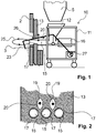
- Fig. 1 shows a charging device according to the invention for a glass melting system in a schematic diagram.
- the in Fig. 1 The basic structure of the loading device 10 according to the invention shown applies to all of the exemplary embodiments described below.
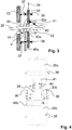
- the bulk material passes via a funnel-shaped loading opening 12 to three essentially horizontally running conveying devices 15 which are arranged next to one another in the horizontal direction (see Fig. 2 ) and which each convey the bulk material into the melting tank 2 by means of a conveyor drive 16.
- the bulk material can also be fed into a doghouse.
- the conveyor 15 can for example be designed as a belt conveyor or screw conveyor be, preferably as in Fig. 2 shown, the conveyor 15 is arranged in a closed, sealing tube.
- the loading device can have only one conveyor device 15, two conveyor devices 15 or more than three conveyor devices 15.
- the loading device 10 has a sealing plate 13, which lies sealingly against the outer wall of the melting tank 2.
- the sealing plate 13 has three adjacent circular openings 17, the inside diameter of which is only a little larger than the outside diameter of the tube of the respective conveying device 15.
- the loading device 10 also has two paddles (sliders) 23, each of which is connected to a separate eccentric drive 27 via a separate movement device in the form of a push rod 20.
- Each paddle 23 executes a cyclical movement, which is indicated by the arrows 25, 26 and which serves to distribute the bulk material deposited on the surface 3 of the glass melt (melt level) in order to improve the melting.
- the cyclical movement is composed of circular movements (arrow 25) and vertical or horizontal movements (see arrows 26).
- the paddle 23 is first immersed in the deposited bulk material and this is shifted towards the center of the tub by means of a horizontal movement of the paddle 23.
- the paddle 23 is then lifted up and returned to the starting position. This cyclical movement is generated by the eccentric drive 27 connected to the push rod 20.
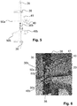
- each bushing 19 is provided for each push rod 20. Due to the mobility of the push rod 20 during operation of the loading device, each bushing 19 must be made significantly larger than the diameter of the push rod 20 would actually require. Without appropriate countermeasures, this free space causes dust and exhaust gas to be discharged from the glass melting system.
- an annular nozzle 30a is provided on a sliding plate 35 on the front side of the sliding plate 35 (ie on the side facing the glass melting system).
- the ring nozzle 30a is arranged at the edge of a continuous opening 34 in the sliding plate 35, through which the push rod 20 is guided.
- the opening 34 in the sliding plate 35 has a smaller cross-sectional area (or smaller horizontal and / or vertical diameter) than the bushing 19 of the sealing plate 13.
- the ring nozzle 30a has a distance d from the bushing 19 of, for example, a maximum of 40 cm.
- the ring nozzle is arranged at a smaller distance d on the bushing 19.
- the gas emerging from the ring nozzle 30a and directed in the direction of the feedthrough 19 (see arrows 44), for example air, generates a counterpressure which acts against dust and exhaust gas flowing in the direction of the feedthrough 19 and thereby prevents it from emerging from the glass melting system.
- the resultant sealing of the glass melting system functions to a certain extent without contact, ie without mechanical contact with the glass melting system or with the sealing plate 13. This reduces heating of the ring nozzle 30a.
- the gas is supplied by means of a gas supply 46a, which is connected to the ring nozzle 30a.
- the ring nozzle 30a is designed as a circular ring or elliptical ring and preferably completely surrounds the push rod 20.
- the annular nozzle 30 consists of one or more annular or elliptical tubular element (s) with a preferably flexible connection for the supply of air.
- the tubular element has the entire length, i.e. over the entire circumference, a plurality of openings, which are arranged such that the air emerging from these openings flows in the direction of passage 19 of the sealing plate 13 or the glass melting system 2.
- a plurality of ring nozzles 30a can also be provided, each ring nozzle 30a each having a different angle of the flow of the emerging air.
- the sliding plate 35 with which the ring nozzle 30a is fixedly connected, is movably guided vertically between two pairs of rollers 37, 38 (see double arrow 39).
- the movement of the sliding plate 35 runs parallel to the surface of the sealing plate 13.
- the rollers 37 lying on the side of the melting tank 2 are firmly connected to the sealing plate 13.
- the same also applies to the rollers 38 lying on the side of the sliding plate 35 opposite the melting tank 2.
- the rollers 37, 38 are each arranged in the vertical direction along the sliding plate 35 above and below the ring nozzle 30a in order to secure the sliding plate 35 . Due to the vertical mobility of the sliding plate (see arrow 39) and thus the ring nozzle 30a, the ring nozzle 30a can follow the movement of the push rod 20 in the vertical direction.
- the push plate 35 also has a support roller 40 which supports the push plate 35 on the push rod 20, although the push rod 20 moves in its horizontal movement in the horizontal direction.
- the support roller 40 is fastened to the sliding plate 35 by means of a strut 41.
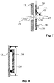
- FIG. 4 to 6 and 10th show the sliding plate 35 of another embodiment of a loading device according to the invention in different views.
- the sliding plate can be made in two parts, consisting of an upper part 35a and a lower part 35b.
- the nozzle ring 30b which in this exemplary embodiment is arranged on the side of the sliding plate 35a, 35b facing away from the glass melting system, is designed in two parts.
- the first part 35a and the second part 35b of the sliding plate and both parts of the nozzle ring 30b can be arranged around the push rod 20 when the loading device is being installed and can be fastened to one another by means of fastening screws 36.
- baffles 50a, 50b are provided in this exemplary embodiment, which guide the gas emerging from the ring nozzle 30b in the direction of passage 19 of the sealing plate 13 or glass melting system.
- Fig. 10 shown variant does not have these baffles.
- Each of the shell-shaped guide plates 50a, 50b is perpendicular or at a large angle to the surface of the sliding plate 35 and also has, as in particular, from Fig. 6 it can be seen a concave curve through which the gas emerging from the ring nozzle 30b is directed particularly effectively in the direction of the passage 19.
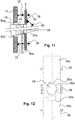
- Fig. 7 It should be shown that the mobility of the sliding plate 35 in the vertical direction can also be achieved by only two rollers 38 arranged one below the other on the same side of the sliding plate 35.
- the rollers 38 are arranged on the side of the sliding plate facing away from the glass melting system.
- the rollers 38 are also how Fig. 8 shows, attached to the sealing plate 13 and spaced from this.
- the sliding plate 35 is preferably provided with a corresponding spring device, not shown permanently pressed against the rollers 38 to effect the spatial fixation of the sliding plate 35.
- the gas nozzles are not shown in the representation of this embodiment.
- the exemplary embodiments shown have two ring nozzles 30a, 30b, the first ring nozzle 30a being arranged on the side of the sliding plate 35 facing the glass melting system and the second ring nozzle 30b being arranged on the side of the sliding plate facing away from the glass melting system.
- Each ring nozzle 30a, 30b is attached to the circumferential edge of the opening 34 of the sliding plate 35 and is provided with a separate gas supply 46a, 46b.
- the embodiment according to 11 and 12 has only on the side of the sliding plate 35 facing the glass melting system an annular nozzle 30a and additional guide plates 50a, 50b analogous to the exemplary embodiment according to FIG 4 to 6 .
- the annular nozzle 30a arranged on the side of the sliding plate 35 facing the glass melting plant is placed directly between the guide plates 50a, 50b.
- the diameter of the nozzle ring or the distance the gas nozzles arranged around the push rod are adapted to the size of the respective bushing.
Landscapes
- Chemical & Material Sciences (AREA)
- Engineering & Computer Science (AREA)
- Materials Engineering (AREA)
- Organic Chemistry (AREA)
- Glass Melting And Manufacturing (AREA)
- Joining Of Glass To Other Materials (AREA)
Priority Applications (1)
| Application Number | Priority Date | Filing Date | Title |
|---|---|---|---|
| PL18199480T PL3470381T3 (pl) | 2017-10-12 | 2018-10-10 | Urządzenie załadowcze dla instalacji do wytopu szkła |
Applications Claiming Priority (1)
| Application Number | Priority Date | Filing Date | Title |
|---|---|---|---|
| DE102017123803.4A DE102017123803A1 (de) | 2017-10-12 | 2017-10-12 | Beschickungsvorrichtung für eine Glasschmelzanlage |
Publications (2)
| Publication Number | Publication Date |
|---|---|
| EP3470381A1 EP3470381A1 (de) | 2019-04-17 |
| EP3470381B1 true EP3470381B1 (de) | 2020-04-22 |
Family
ID=63832262
Family Applications (1)
| Application Number | Title | Priority Date | Filing Date |
|---|---|---|---|
| EP18199480.7A Active EP3470381B1 (de) | 2017-10-12 | 2018-10-10 | Beschickungsvorrichtung für eine glasschmelzanlage |
Country Status (4)
| Country | Link |
|---|---|
| US (1) | US10800694B2 (pl) |
| EP (1) | EP3470381B1 (pl) |
| DE (1) | DE102017123803A1 (pl) |
| PL (1) | PL3470381T3 (pl) |
Families Citing this family (3)
| Publication number | Priority date | Publication date | Assignee | Title |
|---|---|---|---|---|
| US11912608B2 (en) | 2019-10-01 | 2024-02-27 | Owens-Brockway Glass Container Inc. | Glass manufacturing |
| US12252434B2 (en) | 2020-09-30 | 2025-03-18 | Owens-Brockway Glass Container Inc. | Feeder alcove and batch feeding apparats for a melter |
| MX2023003707A (es) * | 2020-09-30 | 2023-05-26 | Owens Brockway Glass Container | Carga sumergida de materia prima de recipientes de fusion. |
Family Cites Families (4)
| Publication number | Priority date | Publication date | Assignee | Title |
|---|---|---|---|---|
| US2212358A (en) * | 1938-04-16 | 1940-08-20 | Libbey Owens Ford Glass Co | Apparatus for feeding batch to glass furnaces |
| US2398952A (en) * | 1941-12-22 | 1946-04-23 | Henry J Nachod | Apparatus for manufacturing silica glass |
| GB664869A (en) * | 1948-07-16 | 1952-01-16 | Verreries Du Puy De Dome Sa | Improvements in or relating to tank furnaces |
| DE102010035893B3 (de) | 2010-08-31 | 2012-01-19 | Beteiligungen Sorg Gmbh & Co. Kg | Beschickungsvorrichtung für Glasschmelzanlagen und Verfahren zum Einlegen von partikelförmigem Beschickungsgut |
-
2017
- 2017-10-12 DE DE102017123803.4A patent/DE102017123803A1/de not_active Ceased
-
2018
- 2018-10-10 EP EP18199480.7A patent/EP3470381B1/de active Active
- 2018-10-10 PL PL18199480T patent/PL3470381T3/pl unknown
- 2018-10-11 US US16/157,909 patent/US10800694B2/en not_active Expired - Fee Related
Non-Patent Citations (1)
| Title |
|---|
| None * |
Also Published As
| Publication number | Publication date |
|---|---|
| DE102017123803A1 (de) | 2019-04-18 |
| EP3470381A1 (de) | 2019-04-17 |
| US10800694B2 (en) | 2020-10-13 |
| PL3470381T3 (pl) | 2020-10-05 |
| US20190112214A1 (en) | 2019-04-18 |
Similar Documents
| Publication | Publication Date | Title |
|---|---|---|
| EP3470381B1 (de) | Beschickungsvorrichtung für eine glasschmelzanlage | |
| EP2611743B1 (de) | Beschickungsvorrichtung für glasschmelzanlagen | |
| WO2016134492A1 (de) | Verfahren und vorrichtung zur fragmentierung und/oder schwächung von schüttfähigem material mittels hochspannungsentladungen | |
| DE102018202011A1 (de) | Schüttgutweiche und Schüttgut-Beschickungsanlage mit einer Schüttgutweiche | |
| DE3139937C2 (pl) | ||
| DE19545419A1 (de) | Vorrichtung zur Bereitstellung, Orientierung und Ordnung von Werkstücken | |
| DE2715179A1 (de) | Vorrichtung zur anordnung einer blechplatte auf einem weitergabefoerderer | |
| DE2432857A1 (de) | Verfahren und vorrichtung zum vorwaermen von schuettgut | |
| DE10137520B4 (de) | Rostfeuerung | |
| DE102010015591B3 (de) | Dosierorgan | |
| EP3181497B1 (de) | Umlenkeinheit für pneumatische förderanlage | |
| DE3146546A1 (de) | Adsorber, sowie verfahren zum betreiben des adsorbers | |
| DE2812628C2 (de) | Förderbandreinigungseinrichtung | |
| DE2022909B2 (de) | Hochofenbeschickungsvorrichtung | |
| EP3524549A1 (de) | Schüttguttrichter und schüttgut-beschickungsanlage mit einem schüttguttrichter | |
| DE202019105677U1 (de) | Belüftungsleiste für ein Silo | |
| DE3304339A1 (de) | Vorrichtung zur wiederverarbeitung von bei der herstellung von kunststoffolien anfallenden randstreifen | |
| DE102022105728A1 (de) | Teigzuführung mit lokal eingeschränktem durchlassquerschnitt | |
| DE3102270C2 (pl) | ||
| AT412786B (de) | Verfahren zum chargieren von schüttfähigem material und vorrichtung zur durchführung des verfahrens | |
| DE102006036904B4 (de) | Vorrichtung und Verfahren zur Entfernung von Schlacken aus einem Entschlacker, Entschlacker und Verfahren zum Auslegen des Bodens eines Entschlackers | |
| EP2810881A1 (de) | Station einer Sackfüllanlage zur Befüllung mit Schüttgut | |
| DE102012111308A1 (de) | Fallschachtanordnung, insbesondere für eine Vorrichtung zur Beleimung von Partikeln im Zuge der Herstellung von Werkstoffplatten | |
| DE3239352A1 (de) | Vorrichtung zur trockenen kuehlung von heissem schuettgut, insbesondere von heissem koks | |
| DE2245390A1 (de) | Vorrichtung zum kontinuierlichen abschrecken einer sich in einer begrenzten ebene bewegenden heissen metallplatte |
Legal Events
| Date | Code | Title | Description |
|---|---|---|---|
| PUAI | Public reference made under article 153(3) epc to a published international application that has entered the european phase |
Free format text: ORIGINAL CODE: 0009012 |
|
| STAA | Information on the status of an ep patent application or granted ep patent |
Free format text: STATUS: THE APPLICATION HAS BEEN PUBLISHED |
|
| AK | Designated contracting states |
Kind code of ref document: A1 Designated state(s): AL AT BE BG CH CY CZ DE DK EE ES FI FR GB GR HR HU IE IS IT LI LT LU LV MC MK MT NL NO PL PT RO RS SE SI SK SM TR |
|
| AX | Request for extension of the european patent |
Extension state: BA ME |
|
| STAA | Information on the status of an ep patent application or granted ep patent |
Free format text: STATUS: REQUEST FOR EXAMINATION WAS MADE |
|
| 17P | Request for examination filed |
Effective date: 20190815 |
|
| RBV | Designated contracting states (corrected) |
Designated state(s): AL AT BE BG CH CY CZ DE DK EE ES FI FR GB GR HR HU IE IS IT LI LT LU LV MC MK MT NL NO PL PT RO RS SE SI SK SM TR |
|
| GRAP | Despatch of communication of intention to grant a patent |
Free format text: ORIGINAL CODE: EPIDOSNIGR1 |
|
| STAA | Information on the status of an ep patent application or granted ep patent |
Free format text: STATUS: GRANT OF PATENT IS INTENDED |
|
| RIC1 | Information provided on ipc code assigned before grant |
Ipc: C03B 3/00 20060101AFI20191118BHEP |
|
| INTG | Intention to grant announced |
Effective date: 20191206 |
|
| GRAS | Grant fee paid |
Free format text: ORIGINAL CODE: EPIDOSNIGR3 |
|
| GRAA | (expected) grant |
Free format text: ORIGINAL CODE: 0009210 |
|
| STAA | Information on the status of an ep patent application or granted ep patent |
Free format text: STATUS: THE PATENT HAS BEEN GRANTED |
|
| AK | Designated contracting states |
Kind code of ref document: B1 Designated state(s): AL AT BE BG CH CY CZ DE DK EE ES FI FR GB GR HR HU IE IS IT LI LT LU LV MC MK MT NL NO PL PT RO RS SE SI SK SM TR |
|
| REG | Reference to a national code |
Ref country code: CH Ref legal event code: EP |
|
| REG | Reference to a national code |
Ref country code: IE Ref legal event code: FG4D Free format text: LANGUAGE OF EP DOCUMENT: GERMAN |
|
| REG | Reference to a national code |
Ref country code: DE Ref legal event code: R096 Ref document number: 502018001263 Country of ref document: DE |
|
| REG | Reference to a national code |
Ref country code: AT Ref legal event code: REF Ref document number: 1259865 Country of ref document: AT Kind code of ref document: T Effective date: 20200515 |
|
| REG | Reference to a national code |
Ref country code: LT Ref legal event code: MG4D |
|
| REG | Reference to a national code |
Ref country code: NL Ref legal event code: MP Effective date: 20200422 |
|
| PG25 | Lapsed in a contracting state [announced via postgrant information from national office to epo] |
Ref country code: IS Free format text: LAPSE BECAUSE OF FAILURE TO SUBMIT A TRANSLATION OF THE DESCRIPTION OR TO PAY THE FEE WITHIN THE PRESCRIBED TIME-LIMIT Effective date: 20200822 Ref country code: GR Free format text: LAPSE BECAUSE OF FAILURE TO SUBMIT A TRANSLATION OF THE DESCRIPTION OR TO PAY THE FEE WITHIN THE PRESCRIBED TIME-LIMIT Effective date: 20200723 Ref country code: NO Free format text: LAPSE BECAUSE OF FAILURE TO SUBMIT A TRANSLATION OF THE DESCRIPTION OR TO PAY THE FEE WITHIN THE PRESCRIBED TIME-LIMIT Effective date: 20200722 Ref country code: FI Free format text: LAPSE BECAUSE OF FAILURE TO SUBMIT A TRANSLATION OF THE DESCRIPTION OR TO PAY THE FEE WITHIN THE PRESCRIBED TIME-LIMIT Effective date: 20200422 Ref country code: SE Free format text: LAPSE BECAUSE OF FAILURE TO SUBMIT A TRANSLATION OF THE DESCRIPTION OR TO PAY THE FEE WITHIN THE PRESCRIBED TIME-LIMIT Effective date: 20200422 Ref country code: LT Free format text: LAPSE BECAUSE OF FAILURE TO SUBMIT A TRANSLATION OF THE DESCRIPTION OR TO PAY THE FEE WITHIN THE PRESCRIBED TIME-LIMIT Effective date: 20200422 Ref country code: PT Free format text: LAPSE BECAUSE OF FAILURE TO SUBMIT A TRANSLATION OF THE DESCRIPTION OR TO PAY THE FEE WITHIN THE PRESCRIBED TIME-LIMIT Effective date: 20200824 Ref country code: NL Free format text: LAPSE BECAUSE OF FAILURE TO SUBMIT A TRANSLATION OF THE DESCRIPTION OR TO PAY THE FEE WITHIN THE PRESCRIBED TIME-LIMIT Effective date: 20200422 |
|
| PG25 | Lapsed in a contracting state [announced via postgrant information from national office to epo] |
Ref country code: BG Free format text: LAPSE BECAUSE OF FAILURE TO SUBMIT A TRANSLATION OF THE DESCRIPTION OR TO PAY THE FEE WITHIN THE PRESCRIBED TIME-LIMIT Effective date: 20200722 Ref country code: RS Free format text: LAPSE BECAUSE OF FAILURE TO SUBMIT A TRANSLATION OF THE DESCRIPTION OR TO PAY THE FEE WITHIN THE PRESCRIBED TIME-LIMIT Effective date: 20200422 Ref country code: LV Free format text: LAPSE BECAUSE OF FAILURE TO SUBMIT A TRANSLATION OF THE DESCRIPTION OR TO PAY THE FEE WITHIN THE PRESCRIBED TIME-LIMIT Effective date: 20200422 Ref country code: HR Free format text: LAPSE BECAUSE OF FAILURE TO SUBMIT A TRANSLATION OF THE DESCRIPTION OR TO PAY THE FEE WITHIN THE PRESCRIBED TIME-LIMIT Effective date: 20200422 |
|
| PG25 | Lapsed in a contracting state [announced via postgrant information from national office to epo] |
Ref country code: AL Free format text: LAPSE BECAUSE OF FAILURE TO SUBMIT A TRANSLATION OF THE DESCRIPTION OR TO PAY THE FEE WITHIN THE PRESCRIBED TIME-LIMIT Effective date: 20200422 |
|
| REG | Reference to a national code |
Ref country code: DE Ref legal event code: R097 Ref document number: 502018001263 Country of ref document: DE |
|
| PG25 | Lapsed in a contracting state [announced via postgrant information from national office to epo] |
Ref country code: DK Free format text: LAPSE BECAUSE OF FAILURE TO SUBMIT A TRANSLATION OF THE DESCRIPTION OR TO PAY THE FEE WITHIN THE PRESCRIBED TIME-LIMIT Effective date: 20200422 Ref country code: EE Free format text: LAPSE BECAUSE OF FAILURE TO SUBMIT A TRANSLATION OF THE DESCRIPTION OR TO PAY THE FEE WITHIN THE PRESCRIBED TIME-LIMIT Effective date: 20200422 Ref country code: SM Free format text: LAPSE BECAUSE OF FAILURE TO SUBMIT A TRANSLATION OF THE DESCRIPTION OR TO PAY THE FEE WITHIN THE PRESCRIBED TIME-LIMIT Effective date: 20200422 Ref country code: RO Free format text: LAPSE BECAUSE OF FAILURE TO SUBMIT A TRANSLATION OF THE DESCRIPTION OR TO PAY THE FEE WITHIN THE PRESCRIBED TIME-LIMIT Effective date: 20200422 Ref country code: ES Free format text: LAPSE BECAUSE OF FAILURE TO SUBMIT A TRANSLATION OF THE DESCRIPTION OR TO PAY THE FEE WITHIN THE PRESCRIBED TIME-LIMIT Effective date: 20200422 |
|
| PG25 | Lapsed in a contracting state [announced via postgrant information from national office to epo] |
Ref country code: SK Free format text: LAPSE BECAUSE OF FAILURE TO SUBMIT A TRANSLATION OF THE DESCRIPTION OR TO PAY THE FEE WITHIN THE PRESCRIBED TIME-LIMIT Effective date: 20200422 |
|
| PLBE | No opposition filed within time limit |
Free format text: ORIGINAL CODE: 0009261 |
|
| STAA | Information on the status of an ep patent application or granted ep patent |
Free format text: STATUS: NO OPPOSITION FILED WITHIN TIME LIMIT |
|
| 26N | No opposition filed |
Effective date: 20210125 |
|
| PG25 | Lapsed in a contracting state [announced via postgrant information from national office to epo] |
Ref country code: SI Free format text: LAPSE BECAUSE OF FAILURE TO SUBMIT A TRANSLATION OF THE DESCRIPTION OR TO PAY THE FEE WITHIN THE PRESCRIBED TIME-LIMIT Effective date: 20200422 |
|
| PG25 | Lapsed in a contracting state [announced via postgrant information from national office to epo] |
Ref country code: MC Free format text: LAPSE BECAUSE OF FAILURE TO SUBMIT A TRANSLATION OF THE DESCRIPTION OR TO PAY THE FEE WITHIN THE PRESCRIBED TIME-LIMIT Effective date: 20200422 Ref country code: LU Free format text: LAPSE BECAUSE OF NON-PAYMENT OF DUE FEES Effective date: 20201010 |
|
| REG | Reference to a national code |
Ref country code: BE Ref legal event code: MM Effective date: 20201031 |
|
| PG25 | Lapsed in a contracting state [announced via postgrant information from national office to epo] |
Ref country code: BE Free format text: LAPSE BECAUSE OF NON-PAYMENT OF DUE FEES Effective date: 20201031 |
|
| PG25 | Lapsed in a contracting state [announced via postgrant information from national office to epo] |
Ref country code: IE Free format text: LAPSE BECAUSE OF NON-PAYMENT OF DUE FEES Effective date: 20201010 |
|
| REG | Reference to a national code |
Ref country code: CH Ref legal event code: PL |
|
| PG25 | Lapsed in a contracting state [announced via postgrant information from national office to epo] |
Ref country code: TR Free format text: LAPSE BECAUSE OF FAILURE TO SUBMIT A TRANSLATION OF THE DESCRIPTION OR TO PAY THE FEE WITHIN THE PRESCRIBED TIME-LIMIT Effective date: 20200422 Ref country code: MT Free format text: LAPSE BECAUSE OF FAILURE TO SUBMIT A TRANSLATION OF THE DESCRIPTION OR TO PAY THE FEE WITHIN THE PRESCRIBED TIME-LIMIT Effective date: 20200422 Ref country code: CY Free format text: LAPSE BECAUSE OF FAILURE TO SUBMIT A TRANSLATION OF THE DESCRIPTION OR TO PAY THE FEE WITHIN THE PRESCRIBED TIME-LIMIT Effective date: 20200422 |
|
| PG25 | Lapsed in a contracting state [announced via postgrant information from national office to epo] |
Ref country code: MK Free format text: LAPSE BECAUSE OF FAILURE TO SUBMIT A TRANSLATION OF THE DESCRIPTION OR TO PAY THE FEE WITHIN THE PRESCRIBED TIME-LIMIT Effective date: 20200422 |
|
| PG25 | Lapsed in a contracting state [announced via postgrant information from national office to epo] |
Ref country code: LI Free format text: LAPSE BECAUSE OF NON-PAYMENT OF DUE FEES Effective date: 20211031 Ref country code: CH Free format text: LAPSE BECAUSE OF NON-PAYMENT OF DUE FEES Effective date: 20211031 |
|
| REG | Reference to a national code |
Ref country code: DE Ref legal event code: R082 Ref document number: 502018001263 Country of ref document: DE Representative=s name: WSL PATENTANWAELTE PARTNERSCHAFT MBB, DE |
|
| REG | Reference to a national code |
Ref country code: AT Ref legal event code: MM01 Ref document number: 1259865 Country of ref document: AT Kind code of ref document: T Effective date: 20231010 |
|
| PG25 | Lapsed in a contracting state [announced via postgrant information from national office to epo] |
Ref country code: AT Free format text: LAPSE BECAUSE OF NON-PAYMENT OF DUE FEES Effective date: 20231010 |
|
| PG25 | Lapsed in a contracting state [announced via postgrant information from national office to epo] |
Ref country code: AT Free format text: LAPSE BECAUSE OF NON-PAYMENT OF DUE FEES Effective date: 20231010 |
|
| PGFP | Annual fee paid to national office [announced via postgrant information from national office to epo] |
Ref country code: DE Payment date: 20251016 Year of fee payment: 8 |
|
| PGFP | Annual fee paid to national office [announced via postgrant information from national office to epo] |
Ref country code: GB Payment date: 20251022 Year of fee payment: 8 |
|
| PGFP | Annual fee paid to national office [announced via postgrant information from national office to epo] |
Ref country code: IT Payment date: 20251024 Year of fee payment: 8 |
|
| PGFP | Annual fee paid to national office [announced via postgrant information from national office to epo] |
Ref country code: FR Payment date: 20251030 Year of fee payment: 8 |
|
| PGFP | Annual fee paid to national office [announced via postgrant information from national office to epo] |
Ref country code: CZ Payment date: 20251002 Year of fee payment: 8 |
|
| PGFP | Annual fee paid to national office [announced via postgrant information from national office to epo] |
Ref country code: PL Payment date: 20251002 Year of fee payment: 8 |
|
| PGFP | Annual fee paid to national office [announced via postgrant information from national office to epo] |
Ref country code: AT Payment date: 20260410 Year of fee payment: 5 |