EP3470295B1 - Automatic decoupling mechanism for vehicle coupler - Google Patents
Automatic decoupling mechanism for vehicle coupler Download PDFInfo
- Publication number
- EP3470295B1 EP3470295B1 EP17836441.0A EP17836441A EP3470295B1 EP 3470295 B1 EP3470295 B1 EP 3470295B1 EP 17836441 A EP17836441 A EP 17836441A EP 3470295 B1 EP3470295 B1 EP 3470295B1
- Authority
- EP
- European Patent Office
- Prior art keywords
- coupler
- rotating member
- coupler knuckle
- knuckle spindle
- boss
- Prior art date
- Legal status (The legal status is an assumption and is not a legal conclusion. Google has not performed a legal analysis and makes no representation as to the accuracy of the status listed.)
- Active
Links
- 230000007246 mechanism Effects 0.000 title claims description 29
- 238000010168 coupling process Methods 0.000 claims description 34
- 230000008878 coupling Effects 0.000 claims description 22
- 238000005859 coupling reaction Methods 0.000 claims description 22
- 238000000034 method Methods 0.000 description 8
- 230000008569 process Effects 0.000 description 6
- 230000004044 response Effects 0.000 description 5
- 238000010586 diagram Methods 0.000 description 4
- 230000000694 effects Effects 0.000 description 3
- 238000012423 maintenance Methods 0.000 description 3
- 230000008859 change Effects 0.000 description 2
- 230000006872 improvement Effects 0.000 description 2
- 239000003973 paint Substances 0.000 description 2
- 230000009286 beneficial effect Effects 0.000 description 1
- 238000007796 conventional method Methods 0.000 description 1
- 238000003754 machining Methods 0.000 description 1
- 230000008092 positive effect Effects 0.000 description 1
Images


Classifications
-
- B—PERFORMING OPERATIONS; TRANSPORTING
- B61—RAILWAYS
- B61G—COUPLINGS; DRAUGHT AND BUFFING APPLIANCES
- B61G3/00—Couplings comprising mating parts of similar shape or form which can be coupled without the use of any additional element or elements
- B61G3/10—Couplings comprising mating parts of similar shape or form which can be coupled without the use of any additional element or elements with coupling heads in the form of hook-like interengaging rigid jaws, e.g. "Willison" type
- B61G3/14—Control devices, e.g. for uncoupling
-
- B—PERFORMING OPERATIONS; TRANSPORTING
- B61—RAILWAYS
- B61G—COUPLINGS; DRAUGHT AND BUFFING APPLIANCES
- B61G7/00—Details or accessories
-
- B—PERFORMING OPERATIONS; TRANSPORTING
- B61—RAILWAYS
- B61G—COUPLINGS; DRAUGHT AND BUFFING APPLIANCES
- B61G3/00—Couplings comprising mating parts of similar shape or form which can be coupled without the use of any additional element or elements
- B61G3/16—Couplings comprising mating parts of similar shape or form which can be coupled without the use of any additional element or elements with coupling heads rigidly connected by rotatable hook plates or discs and balancing links, the coupling members forming a parallelogram, e.g. "Scharfenberg" type
- B61G3/20—Control devices, e.g. for uncoupling
-
- B—PERFORMING OPERATIONS; TRANSPORTING
- B61—RAILWAYS
- B61G—COUPLINGS; DRAUGHT AND BUFFING APPLIANCES
- B61G7/00—Details or accessories
- B61G7/02—Hand tools for coupling or uncoupling
Landscapes
- Engineering & Computer Science (AREA)
- Mechanical Engineering (AREA)
- Transmission Devices (AREA)
- Hooks, Suction Cups, And Attachment By Adhesive Means (AREA)
- Quick-Acting Or Multi-Walled Pipe Joints (AREA)
- Mutual Connection Of Rods And Tubes (AREA)
- Mechanical Operated Clutches (AREA)
Description
- The present application belongs to the technical field of coupling devices for train couplers and particularly relates to an automatic uncoupling mechanism for couplers.
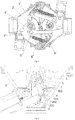
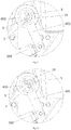
- As the basic composition of a coupling device for couplers, an uncoupling device functions to push a coupler knuckle mechanism to rotate so as to uncouple couplers. Prior uncoupling methods include manual uncoupling and automatic uncoupling, wherein the prior automatic uncoupling method for railway vehicles in China is pneumatic uncoupling. A conventional uncoupling device is shown in
Fig. 1 . Two uncoupling mechanisms are shown inFig. 1 . Since the two uncoupling mechanisms are the same in structure, only one of them will be described. The conventional uncoupling device includes a coupler body 1' in which a coupler knuckle spindle 2' is provided. The coupler knuckle spindle 2' passes through a coupler knuckle 3' and is able to push the coupler knuckle 3' to rotate. The coupler knuckle 3' is connected to a coupling rod 4'. For example, the connection between the coupler knuckle 3' and the coupling rod 4' may be realized by a pin 5'. The uncoupling device further includes a tension spring 6'. One end of the tension spring 6' is connected to the coupling rod 4', while the other end thereof is connected to the coupler body 1'. Acylinder piston rod 7' is further provided on the coupler body 1' to provide power for pushing the coupler knuckle 3' to move. During uncoupling by a pneumatic uncoupling approach, thecylinder piston rod 7' is stretched out to directly push the coupler knuckle 3' to rotate. However, since the surface of the coupler knuckle 3' coming into contact with theuncoupling piston rod 7' is relatively short, it is very difficult to ensure that the stress direction of the coupler knuckle 3' is always along the direction of thepiston rod 7'. As a result,
there will be some problems, such as the coupler knuckle 3' applying a large lateral force to thecylinder piston rod 7' and thecylinder piston rod 7' causing damage to the paint on the coupler knuckle. - In order to solve the above technical problems, the Chinese Utility Model
CN200981560Y discloses a compact tight-lock coupler, wherein an uncoupling cylinder is disposed in an inner cavity of a coupler body, and one end of the uncoupling cylinder is hinged to an uncoupling crank while the other end thereof is mounted on an inner wall of the coupler body. During uncoupling, uncoupling cylinders of two couplers are inflated, and piston push rods drive uncoupling cranks to push two coupler knuckles to rotate until the two couplers may be uncoupled from each other. After the two couplers are uncoupled from each other, the coupler knuckles return to the to-be-coupled positions due to the tension of tension springs. The uncoupling device provides a technical means for hinging a cylinder piston rod to a coupler knuckle mechanism, so that the technical problems of the large lateral force applied to the cylinder piston and the damage to the paint on the coupler knuckle caused by the cylinder piston rod are solved during uncoupling. However, this uncoupling device still has the following technical problems. - During the coupler coupling process, coupler knuckles of two couplers are pushed to rotate by thrust forces from two trains. After the couplers are rotated to a maximum angle, due to the resistance from the cylinder rod, the coupler knuckles are difficult to quickly rotate and lock the two couplers under the tension of the tension springs.
- In order to solve the above technical problems, the Chinese Utility Model
CN201136515Y discloses a link-type automatic uncoupling device for tight-lock couplers, wherein a central shaft is disposed in an inner cavity of a coupler knuckle, a spindle is fixedly mounted on the central shaft, an uncoupling crank is hinged to the spindle by a connecting rod, and a cylinder piston of an uncoupling cylinder is positioned at the tail of the spindle. In addition, the uncoupling device further provides a spring sheathed on the cylinder piston. With the uncoupling device, during the coupler coupling process, the load experienced by the tension spring when pulling the coupler knuckle to return to its position is relieved. However, in this uncoupling device, the resistance generated when the tension spring pulls the coupler knuckle to return to its position is not completely eliminated, so during the coupler coupling process, the coupler knuckle is still very difficult to quickly rotate and lock two couplers under the tension of the tension spring. -
GB1314438A - In view of the problems in the prior automatic uncoupling devices for couplers, the present application provides a novel automatic uncoupling mechanism for couplers.
- The present invention is defined in the claims.
- Compared with the prior art, the advantages and positive effects of the present application are as follows:
- 1. The present application improves the uncoupling mechanism of the existing automatic coupling device for couplers, that is, by providing the first rotating member, the boss and the boss stopper and configuring the split-type connection relationship between the first rotating member and the coupler knuckle spindle, the coupler knuckle spindle may be rotated simultaneously with the first rotating member during the uncoupling process, and independently operated during the coupling process, so as to ensure that the tension spring drives the coupler knuckle to rotate rapidly and lock the coupler, thereby it is beneficial to implement the coupler coupling under the promise of ensuring automatic uncoupling approach of high efficiency.
- 2. The automatic uncoupling mechanism provided by the present application may reduce the lateral force of the coupler knuckle to the driving unit during the uncoupling process of the coupler, and may cause the spring to drive the coupler knuckle to rotate rapidly and lock the coupler during the coupler coupling process.
- 3. The automatic uncoupling approach of the existing railway vehicles in China are all pneumatic uncoupling. However, the pneumatic uncoupling approach has low response speed, difficult maintenance and poor stability, and the pneumatic uncoupling requires an air source, generally an air compressor, with the disadvantages of occupying a large volume and having a large noise, etc. Therefore, by using the electric cylinder, the existing pneumatic uncoupling approach is improved into an electric uncoupling approach, thereby improving the response speed and stability of the automatic uncoupling device for couplers, reducing the maintenance cost of the automatic uncoupling device for couplers, saving space and improving comfort.
- 4. Although the application of the electric uncoupling approach may achieve the technical effect such as the above-mentioned high response speed and high stability, the electric cylinder used in the electric uncoupling approach has a high self-locking force, which has a great hindrance to the couple of the couplers of the automatic uncoupling device for couplers. Therefore, in order to overcome the difficult that the electric uncoupling approach may not be applied to the automatic uncoupling device for couplers, the present application combines the split-type connection approach of the first rotating member with the coupler knuckle spindle and the electric uncoupling approach, thereby improving the stability of the automatic uncoupling device for couplers and the efficiency of uncoupling, and ensuring the smooth implement of the couplers coupling process.
-
Fig. 1 is a schematic structure diagram of a prior uncoupling device for couplers; -
Fig. 2 is a top view of an automatic uncoupling mechanism for couplers according to the present application; -
Fig. 3 is a sectional view ofFig. 2 taken along section A-A; -
Fig. 4 is a sectional view ofFig. 2 taken along section B-B; -
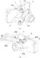
Fig. 5 is a left perspective view of the automatic uncoupling mechanism for couplers; -
Fig. 6 is a right perspective view of the automatic uncoupling mechanism for couplers; -
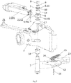
Fig. 7 is an exploded view corresponding toFig. 6 ; -
Fig. 8 is a connection diagram of components after a coupler body is omitted; -
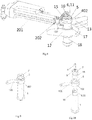
Fig. 9 is a matching view of a boss and a groove in another implementation; -
Fig. 10 is an exploded view ofFig. 9 ; -
Fig. 11 is a first schematic diagram of a manual uncoupling device; -
Fig. 12 is a second schematic diagram of the manual uncoupling device; -
Fig. 13 is a partial view of the automatic uncoupling mechanism for couplers when two couplers may be completely uncoupled from each other during the coupler uncoupling process; -
Fig. 14 is a partial view of the automatic uncoupling mechanism for couplers after couplers are uncoupled; and -
Fig. 15 is a partial view of the automatic uncoupling mechanism for couplers when coupler knuckles of two couplers are rotated to the maximum angle during the coupler coupling; - In the following, the present application is specifically described by way of exemplary embodiments. However, it should be understood that elements, structures, and features of an embodiment may be beneficially incorporated into other embodiments without further recitation.
- In the description of the present application, it should be noted that the terms "inside", "outside", "up", "down", "front", "back", "left", "right", "clockwise", "anticlockwise" and the like indicate the positional or positional relationship according to the positional relationship shown in the drawings merely for the convenience of describing the present application and the simplified description, but do not indicate or imply a devices or an element referred to must be of a particular orientation, constructed and operated in a particular orientation and therefore should not be construed as limiting the present application. Moreover, the terms "first", "second", "third" and the like are used merely for descriptive purposes and should not be understood as indicating or implying relative importance.
- As shown in
Figs. 2-8 , an automatic uncoupling mechanism for couplers is provided, including acoupler knuckle spindle 1 and adriving unit 2. The drivingunit 2 includes acylinder body 201 hinged to acoupler body 3 and atelescopic member 202 capable of moving in an axial direction of thecylinder body 201. The automatic uncoupling mechanism for couplers further includes a first rotatingmember 4, aboss 5 and aboss stopper 6, wherein the first rotatingmember 4 includes a crank 401 hinged to thetelescopic member 202 and arotating part 402 fixedly connected to thecrank 401. Therotating part 402 is sheathed on thecoupler knuckle spindle 1. The drivingunit 2 unidirectionally drives thetelescopic member 202 so that therotating part 402 drives thecoupler knuckle spindle 1 to unidirectionally rotate by a contact between theboss 5 and theboss stopper 6, so as to realize coupler uncoupling. After thedriving unit 2 drives thetelescopic member 202 to return to its position, the rotation of thecoupler knuckle spindle 1 for achieving coupler coupling is not limited by therotating part 402. - The hinged connection may be a direct hinged connection between components, or may be an indirect hinged connection. As shown in
Figs. 6 and7 , the hinged connection between the drivingunit 2 and thecoupler body 3 may be a hinged connection between a support plate located under the drivingunit 2 with thecoupler body 3, so that the hinged connection between the drivingunit 2 and thecoupler body 3 is an indirect hinged connection; and the direct hinged connection between thetelescopic member 202 and thecrank 401 may be realized by a pin, a fixation member or other conventional components. - In order to prevent the movement of the first rotating
member 4 in an axis direction of thecoupler knuckle spindle 1 from causing the unstable rotation of the first rotatingmember 4, the automatic uncoupling mechanism for couplers further includes a secondrotating member 7 for limiting the movement of therotating part 402 in the axis direction of thecoupler knuckle spindle 1, and the second rotatingmember 7 is fixedly connected to thecoupler knuckle spindle 1. As a preferred embodiment, the second rotatingmember 7 is located above therotating part 402. - By providing the first rotating
member 4, theboss 5 and theboss stopper 6 and by providing the split-type connection between the first rotatingmember 4 and thecoupler knuckle spindle 1, thecoupler knuckle spindle 1 is enabled to simultaneously rotate with the first rotatingmember 4 during the coupler uncoupling process but independently rotate during the coupler coupling process. Consequently, it is ensured that the tension spring drives the coupler knuckle to quickly rotate and lock the couplers, and it is advantageous for smooth coupler coupling under the premise of ensuring high efficiency of the automatic uncoupling approach. - As shown in
Figs. 2-8 , theboss 5 is fixedly mounted above therotating part 402. The secondrotating member 7 is located above therotating part 402 and may be a cover plate structure. Left and right portions of the second rotatingmember 7 come into close contact with the rotating part 402 (as shown inFigs. 3 and 4 ), that is, the second rotatingmember 7 may cover therotating part 402 to avoid the movement of the rotating part in the axial direction. The position of theboss 5 corresponds to that of the second rotatingmember 7. As shown inFigs. 6 and7 , in order to prevent the second rotatingmember 7 from rotating out from thecoupler knuckle spindle 1, the second rotatingmember 7 may be fixed on thecoupler knuckle spindle 1 by two ormore screws 8. During the fixation of thescrews 8, components such aswasher 9 may also be used for purpose of realizing firmer fixation. As shown inFigs. 2-8 , agroove 10 is formed on the second rotatingmember 7, and theboss stopper 6 is a radial sidewall of thegroove 10, i.e., anupper sidewall 11 shown inFig. 2 . - In order to understand the technical solutions of the present application more clearly, the conventional techniques related to the present application will be briefly described herein. As shown in
Figs. 1 andFigs. 6-8 , wherein the reference numerals in the parentheses are reference numerals inFig. 1 , a coupler knuckle spindle 1(2') and a coupler knuckle 12(3') are included in the coupler body 3(1'); the coupler knuckle spindle 1(2') passes through the coupler knuckle 12(3'), and the coupler knuckle spindle 1(2') can push the coupler knuckle 12(3') to rotate; the coupler knuckle 12(3') is connected to a coupling rod 13(4'), both of which may be connected by a pin 14(5'); a tension spring 15(6') is further included in the coupler body 3(1'); and, one end of the tension spring 15(6') is connected to the coupling rod 13(4'), while the other end thereof is connected to the coupler body 3(1'). It should be understood that pushing the coupler knuckle 12(3') by the coupler knuckle spindle 1(2') may be realized by a key 16. Afirst shaft sleeve 17 and asecond shaft sleeve 18 may be further provided on the upper and lower of the coupler knuckle spindle 1(2'), respectively, to ensure the reliable rotation between the coupler knuckle spindle 1(2') and the coupler body 3(1'). These technical solutions may be regarded as prior technical solutions. - In the case of understanding the technical solutions of the present application in combination with the prior art, in order to enable the
coupler knuckle 12 to completely return to its position by thetension spring 15 during the coupler coupling process, as a preferred embodiment, the dimension of thegroove 10 in a circumferential direction of thecoupler knuckle spindle 1 should be greater than or equal to the maximum movement distance of theboss 5. - The maximum movement distance of the boss means that: during uncoupling, it can be ensured that the
boss 5 is able to push (directly or indirectly) thecoupler knuckle spindle 1 to rotate and thus drive thecoupler knuckle 12 and thecoupling rod 13 to a completely uncoupling position; while during coupling, it is ensured that the rotation of theboss 5 will not be hindered by the second rotatingmember 7 or the coupler knuckle spindle 1 (except for friction). - The above specific embodiment has the following advantages. On one hand, by providing the second rotating
member 7, the rotation of therotating part 402 is more stable; on the other hand, by arranging theboss stopper 6 on the second rotatingmember 7 and fixing the second rotatingmember 7 by two ormore screws 8, the relative rotation between the second rotatingmember 7 and thecoupler knuckle spindle 1 is further limited, so that the damage to thecoupler knuckle spindle 1 caused by a direct contact of theboss 5 with thecoupler knuckle spindle 1 is avoided and it is advantageous for ensuring longer service life of thecoupler knuckle spindle 1. - As another variant of the above specific embodiment, as shown in
Figs. 9 and 10 and for ease understanding of the technical solutions, some components are omitted, wherein agroove 10 is formed on a side face of thecoupler knuckle spindle 1 and theboss stopper 6 is aradial sidewall 11 of thegroove 10. During assembly, theboss 5 may be extended into thegroove 10, and by pushing theradial sidewall 11 of thegroove 10, thecoupler knuckle spindle 1 is pushed to rotate. During this process, if a secondrotating member 7 is further provided, the second rotatingmember 7 merely functions to limit the axial movement of therotating part 402 without transferring rotation. Similarly, in order to enable thecoupler knuckle 12 to completely return to its position by thetension spring 15 during the coupler coupling process, the dimension of thegroove 10 in a circumferential direction of thecoupler knuckle spindle 1 is still required to be greater than or equal to the maximum movement distance of theboss 5. - As a variant of the above specific embodiment, the
boss stopper 6 may also be of a block structure (not shown). The block structure may be fixedly mounted on the second rotatingmember 7 and correspond to theboss 5 in terms of position; or the block structure may be fixed on thecoupler knuckle spindle 1 and correspond to theboss 5 in terms of position. - The advantageous of designing the
boss stopper 6 as a block structure is that, compared with the approach of forming thegroove 10, the approach of providing a block structure has no requirement on the dimension limitation and convenient for machining. If the approach of mounting the block structure on thecoupler knuckle spindle 1 is employed, the second rotatingmember 7 merely functions to limit the axial movement of therotating part 402, and the number of thescrews 8 is not limited. - It is to be noted that, for the approach of arranging the
boss stopper 6 on thecoupler knuckle spindle 1, the second rotatingmember 7 may be omitted. In this way, it is also possible to achieve the purpose of ensuring a smooth coupler coupling process by the automatic uncoupling mechanism for couplers in the present application. - According to one example, that is not part of the claimed invention, the specific structures of the
boss 5 and theboss stopper 6 may be changed with each other. For example, in the above specific embodiment, theboss 5 is arranged on therotating part 402, thegroove 10 is arranged on a side face of thecoupler knuckle spindle 1 or on the second rotatingmember 7, and when thetelescopic member 202 is stretched out, a side (as the boss stopper 6) of thegroove 10 is pushed by theboss 5 so as to eventually rotate thecoupler knuckle spindle 1; and after change, the boss may be arranged on a side face of thecoupler knuckle spindle 1 or on the second rotatingmember 7, the groove is formed on therotating part 402, and when thetelescopic member 202 is stretched out, the boss is pushed by a side of the groove so as to eventually rotate thecoupler knuckle spindle 1. - Or, when the originally used
boss stopper 6 is of a block structure, after change, the boss may be arranged on a side face of thecoupler knuckle spindle 1 or on the second rotatingmember 7, and the block structure is arranged on therotating part 402. In this case, when thetelescopic member 202 is stretched out, the boss is pushed by the block structure so as to eventually rotate thecoupler knuckle spindle 1. - As an improvement of the above specific embodiment, as shown in
Figs. 2 and7 , the drivingunit 2 of the automatic uncoupling mechanism for couplers is set as an electric cylinder. By using the electric cylinder, the existing pneumatic uncoupling approach is improved into an electric uncoupling approach, so that the response speed and stability of the automatic uncoupling device for couplers are improved and the maintenance cost thereof is reduced. - It is to be noted that, although the technical effects such as high response speed and high stability can be achieved by replacing the existing pneumatic uncoupling approach with the electric uncoupling approach, the electric cylinder used in the electric uncoupling approach has a very high self-locking force, which will greatly hinder the coupler coupling of the automatic uncoupling device for couplers. Therefore, in order to overcome the difficulty that the electric uncoupling approach cannot be applied to the automatic uncoupling device for couplers, the present application combines the split-type connection approach of the first rotating
member 4 and thecoupler knuckle spindle 1 with the electrical uncoupling approach, so that the stability and uncoupling efficiency of the automatic uncoupling device for couplers can be improved and the smooth coupler coupling process can also be ensured. - As an improvement of the above specific embodiment, as shown in
Figs. 3 and 4 , in order to prevent dry friction from generating between the first rotatingmember 4 and thecoupler knuckle spindle 1 or the second rotatingmember 7 and thus influencing the realization of the technical effects of the present application, asleeve 19 is provided between an inner wall of the first rotatingmember 4 and a side face of thecoupler knuckle spindle 1. - As a preferred embodiment, the present application further provides a
manual uncoupling device 20, which may be used for realizing manual uncoupling for couplers in a case where thecrank 401 or therotating part 402 does not operate properly. As shown inFigs. 11-12 , themanual uncoupling device 20 includes ahandle 21. One end of thehandle 21 is arotating head 22 of a flat plate structure. A clampingmember 23 is provided on a face of the rotatinghead 22. There are one ormore clamping members 23. Optionally, the number of the clamping members is equal to the number of thescrews 8. - When the
screws 8 are embedded into the outer surface of the second rotatingmember 7, the clampingmembers 23 are of a raised structure matched with the screws. As shown inFigs. 11-12 , the clamping members are two raised structures matched with mounting ports of thescrews 8. When thescrews 8 are protruded from the outer surface of the second rotatingmember 7, the clampingmember 23 is of a hole structure (not shown) matched with the screws. No matter how the screws and the clamping members are matched, the operation principle is as follows: when the electric rotation or pneumatic rotation works improperly, the clampingmembers 23 of themanual uncoupling device 20 is matched with thescrews 8 or screw holes, and thehandle 21 is rotated to drive thecoupler knuckle spindle 1 to rotate so as to realize uncoupling. - Now the operation process of the automatic uncoupling mechanism for couplers in the present application will be described by taking the specific structure shown in
Figs. 13-15 as example. - As shown in
Fig. 13 , during the coupler uncoupling, thetelescopic rod 202 is stretched out under the drive of thecylinder body 201 and then drives thecrank 401 to rotate counterclockwise, and thecrank 401 drives therotating part 402 to counterclockwise rotate around the axis of thecoupler knuckle spindle 1. As shown inFig. 13 , the first rotatingmember 4 drives the second rotatingmember 7 to rotate counterclockwise by the work ofboss 5 and theside wall 11 of the groove formed on the second rotatingmember 7. It can be seen fromFigs. 13 and3 that the rotation of the second rotatingmember 7 drives thecoupler knuckle spindle 1 to rotate counterclockwise, and when two couplers can be completely uncoupled from each other, thecoupler knuckle spindle 1 stops rotating. - As shown in
Fig. 14 , after the coupler uncoupling, thetelescopic rod 202 is retracted to the initial position shown inFigs. 2 and14 . Meanwhile, due to the work of thetension spring 15, the second rotatingmember 7 drives thecoupler knuckle spindle 1 to rotate clockwise. - As shown in
Fig. 15 , during the coupler coupling,coupler knuckles 12 of two couplers are pushed to rotate counterclockwise by the thrust forces from two trains, and thecoupler knuckle spindle 1 is driven to rotate counterclockwise until the twocouplers 12 are rotated to the maximum angle and reach the fully opened position (that is, being rotated to the position shown inFig. 15 ). In this case, thecoupler knuckle spindle 1 is rotated clockwise to the initial position shown inFig. 2 due to the tension of thetension spring 15. During the whole coupler coupling process, the first rotatingmember 4 is not rotated.
1' coupler body; 2' coupler knuckle spindle; 3' coupler knuckle; 4' coupling rod; 5' pin; 6' tension spring; 7' cylinder piston rod; 1 coupler knuckle spindle; 2 driving unit; 201 cylinder body; 202 telescopic member; 3 coupler body; 4 first rotating member; 401 crank; 402 rotating part; 5 boss; 6 boss stopper; 7 second rotating member; 8 screw; 9 washer; 10 groove; 11 upper sidewall; 12 coupler knuckle; 13 coupling rod; 14 pin; 15 tension spring; 16 key; 17 first shaft sleeve; 18 second shaft sleeve; 19 sleeve; 20 manual uncoupling device; 21 handle; 22 rotating head; 23 clamping member.
Claims (8)
- An automatic uncoupling mechanism for couplers, comprising
a coupler knuckle spindle (1) and a driving unit (2);
the driving unit (2) comprises a cylinder body (201) hinged to a coupler body (3), and a telescopic member (202) axially movable along the cylinder body (201); whereby it further comprises a first rotating member (4), a boss (5) and a boss stopper (6); the first rotating member (4) comprises a crank (401) hinged to the telescopic member (202), and a rotating part (402) fixedly connected to the crank (401), with the rotating part (402) being sheathed on the coupler knuckle spindle (1);
it further comprises a second rotating member (7) for limiting the movement of the rotating part (402) in an axis direction of the coupler knuckle spindle (1); and the second rotating member (7) is fixedly connected to the coupler knuckle spindle (1);
the boss (5) is fixedly mounted on the rotating part (402);
the boss stopper (6) is arranged on the coupler knuckle spindle (1) or on the second rotating member (7);
the driving unit (2) unidirectionally drives the telescopic member (202) so that the rotating part (402) drives the coupler knuckle spindle (1) to unidirectionally rotate by a contact of the boss (5) with the boss stopper (6), so as to realize coupler uncoupling; and,
after the driving unit (2) drives the telescopic member (202) to return to its position, the rotation of the coupler knuckle spindle (1) for achieving coupler coupling is not limited by the rotating part (402). - The automatic uncoupling mechanism for coupler according to claim 1, wherein, a groove (10) is formed on a side wall of the coupler knuckle spindle (1) or on the second rotating member (7); the boss stopper (6) is a radial sidewall (11) of the groove; and a dimension of the groove (10) in a circumferential direction of the coupler knuckle spindle (1) or the second rotating member (7) is greater than or equal to the maximum movement distance of the boss (5).
- The automatic uncoupling mechanism for coupler according to claim 1, wherein, the boss stopper (6) is of a block structure fixed on the coupler knuckle spindle (1) or on the second rotating member (7).
- The automatic uncoupling mechanism for coupler according to any one of claims 1-3, wherein, the second rotating member (7) is located above the rotating part (402) and is a cover plate structure.
- The automatic uncoupling mechanism for coupler according to any one of claims 1-4, wherein, the driving unit (2) is an electric cylinder.
- The automatic uncoupling mechanism for coupler according to any one of claims 1-5, wherein, a sleeve (19) is provided between an inner wall of the first rotating member (4) and a side face of the coupler knuckle spindle (1).
- The automatic uncoupling mechanism for coupler according to any one of claims 1-6, wherein, the second rotating member (7) is fixed on the coupler knuckle spindle (1).
- The automatic uncoupling mechanism for coupler according to any one of claims 1-7, wherein, the second rotating member (7) is fixed on the coupler knuckle spindle (1) by two or more screws (8).
Applications Claiming Priority (2)
| Application Number | Priority Date | Filing Date | Title |
|---|---|---|---|
| CN201610778788.8A CN106274958B (en) | 2016-08-31 | 2016-08-31 | Hitch solves hook mechanism automatically |
| PCT/CN2017/097009 WO2018024260A1 (en) | 2016-08-31 | 2017-08-11 | Automatic decoupling mechanism for vehicle coupler |
Publications (3)
| Publication Number | Publication Date |
|---|---|
| EP3470295A1 EP3470295A1 (en) | 2019-04-17 |
| EP3470295A4 EP3470295A4 (en) | 2019-07-31 |
| EP3470295B1 true EP3470295B1 (en) | 2020-10-28 |
Family
ID=57673724
Family Applications (1)
| Application Number | Title | Priority Date | Filing Date |
|---|---|---|---|
| EP17836441.0A Active EP3470295B1 (en) | 2016-08-31 | 2017-08-11 | Automatic decoupling mechanism for vehicle coupler |
Country Status (7)
| Country | Link |
|---|---|
| US (1) | US11072353B2 (en) |
| EP (1) | EP3470295B1 (en) |
| JP (1) | JP6773888B2 (en) |
| CN (1) | CN106274958B (en) |
| ES (1) | ES2829641T3 (en) |
| RU (1) | RU2713578C1 (en) |
| WO (1) | WO2018024260A1 (en) |
Cited By (1)
| Publication number | Priority date | Publication date | Assignee | Title |
|---|---|---|---|---|
| EP4339057A1 (en) * | 2022-09-15 | 2024-03-20 | KNORR-BREMSE Systeme für Schienenfahrzeuge GmbH | Method for controlling a digital automatic coupling of railway vehicles and such a digital automatic coupling |
Families Citing this family (18)
| Publication number | Priority date | Publication date | Assignee | Title |
|---|---|---|---|---|
| CN106274958B (en) * | 2016-08-31 | 2018-02-02 | 中车青岛四方车辆研究所有限公司 | Hitch solves hook mechanism automatically |
| CN107031680B (en) * | 2017-04-18 | 2018-09-14 | 青岛思锐科技有限公司 | Coupler-uncoupling control mechanism |
| CN107139960B (en) * | 2017-05-10 | 2023-06-27 | 西南交通大学 | Ultra-light high-strength transition coupler |
| CN108556867B (en) * | 2018-01-26 | 2020-04-24 | 刘晓冰 | Detachable hook mechanism for carriage connection based on gear transmission |
| CN110001701A (en) * | 2018-01-26 | 2019-07-12 | 蔡洪祥 | A kind of removable hitch gear for railway carriage connection |
| CN108773388B (en) * | 2018-07-25 | 2024-02-23 | 中冶赛迪工程技术股份有限公司 | Coupler coupling booster unit |
| CN112172424B (en) * | 2019-07-05 | 2024-03-29 | 中车长春轨道客车股份有限公司 | Automatic unhooking device and automatic unhooking method |
| CN110566833B (en) * | 2019-09-03 | 2020-07-17 | 深圳市海洋王照明工程有限公司 | Inspection lamp |
| DE102021132991A1 (en) | 2020-12-15 | 2022-06-15 | Voith Patent Gmbh | Automatic train coupler and method of uncoupling an automatic train coupler |
| EP4263319A2 (en) | 2020-12-15 | 2023-10-25 | Voith Patent GmbH | Automatic train coupling |
| DE102021111206A1 (en) | 2021-04-30 | 2022-11-03 | Voith Patent Gmbh | Automatic train coupler and method of uncoupling an automatic train coupler |
| DE102021111207A1 (en) | 2021-04-30 | 2022-11-03 | Voith Patent Gmbh | Automatic train coupler and method of uncoupling an automatic train coupler |
| SE2150757A1 (en) * | 2021-06-11 | 2022-12-12 | Dellner Couplers Ab | Coupler comprising a blocking mechanism for preventing coupling of the mechanical coupler |
| CN113335332A (en) * | 2021-06-18 | 2021-09-03 | 中车株洲电力机车有限公司 | Rotary type automatic coupler guiding device, control method and coupler |
| DE102022104692A1 (en) | 2022-02-28 | 2023-08-31 | Voith Patent Gmbh | AUTOMATIC TRAIN COUPLING, GUIDED VEHICLE WITH SUCH AUTOMATIC TRAIN COUPLING AND METHOD FOR DISCOUPLING TWO INTER-COUPLED AUTOMATIC TRAIN COUPLINGS |
| DE102022104693A1 (en) | 2022-02-28 | 2023-08-31 | Voith Patent Gmbh | AUTOMATIC TRAIN COUPLING AND METHOD OF OPERATING AN AUTOMATIC TRAIN COUPLING |
| DE102023125805A1 (en) | 2022-09-28 | 2024-03-28 | Voith Patent Gmbh | AUTOMATIC TRAIN COUPLING, PARTICULARLY FOR A FREIGHT WAGON OF A TRACK-GUIDED VEHICLE |
| DE102022125255A1 (en) | 2022-09-30 | 2024-04-04 | Voith Patent Gmbh | METHOD FOR DISSOLVING AND REASSUMING A TRAIN COMPOSITION, AUTOMATIC TRAIN COUPLING AND TRAIN COMPOSITION |
Family Cites Families (12)
| Publication number | Priority date | Publication date | Assignee | Title |
|---|---|---|---|---|
| NL41502C (en) * | 1933-12-18 | |||
| JPS4634175Y1 (en) * | 1967-06-13 | 1971-11-26 | ||
| GB1328253A (en) * | 1970-08-26 | 1973-08-30 | Mini Verkehrswesen | Arrangement for the uncoupling of rail vehicles having central buffer couplings |
| GB1314438A (en) * | 1970-12-02 | 1973-04-26 | Mini Verkehrswesen | Automatic central buffer couplings for rail vehicles |
| US4073385A (en) * | 1977-01-13 | 1978-02-14 | Walton Products, Inc. | Car coupler |
| US4391380A (en) * | 1981-02-12 | 1983-07-05 | Hoose Demetrius H | Rail car coupler interlock |
| US5503280A (en) * | 1994-04-26 | 1996-04-02 | Westinghouse Air Brake Company | Timed thrust uncoupling mechanism for passenger transit type railway cars |
| CN200981560Y (en) * | 2006-06-28 | 2007-11-28 | 中国北车集团四方车辆研究所 | Compact joint sealing car coupler |
| DE202007001773U1 (en) * | 2007-02-07 | 2007-04-05 | Voith Ag | Coupling arrangement for mechanical connection of adjacent railway car body of multi-section vehicle, has two coupling heads and two closure elements whereby second closure element of both coupling heads has two locking links |
| CN201136515Y (en) * | 2007-12-18 | 2008-10-22 | 中国北车集团四方车辆研究所 | Connecting bar type auto uncoupling device for tight-lock coupler |
| CN202439714U (en) * | 2012-02-28 | 2012-09-19 | 齐齐哈尔轨道交通装备有限责任公司 | Coupler lock for car coupler of railway vehicle and car coupler for railway vehicle |
| CN106274958B (en) * | 2016-08-31 | 2018-02-02 | 中车青岛四方车辆研究所有限公司 | Hitch solves hook mechanism automatically |
-
2016
- 2016-08-31 CN CN201610778788.8A patent/CN106274958B/en active Active
-
2017
- 2017-08-11 WO PCT/CN2017/097009 patent/WO2018024260A1/en unknown
- 2017-08-11 ES ES17836441T patent/ES2829641T3/en active Active
- 2017-08-11 RU RU2019101513A patent/RU2713578C1/en active
- 2017-08-11 EP EP17836441.0A patent/EP3470295B1/en active Active
- 2017-08-11 JP JP2019505044A patent/JP6773888B2/en active Active
-
2019
- 2019-01-09 US US16/244,089 patent/US11072353B2/en active Active
Non-Patent Citations (1)
| Title |
|---|
| None * |
Cited By (1)
| Publication number | Priority date | Publication date | Assignee | Title |
|---|---|---|---|---|
| EP4339057A1 (en) * | 2022-09-15 | 2024-03-20 | KNORR-BREMSE Systeme für Schienenfahrzeuge GmbH | Method for controlling a digital automatic coupling of railway vehicles and such a digital automatic coupling |
Also Published As
| Publication number | Publication date |
|---|---|
| CN106274958B (en) | 2018-02-02 |
| RU2713578C1 (en) | 2020-02-05 |
| ES2829641T3 (en) | 2021-06-01 |
| JP6773888B2 (en) | 2020-10-21 |
| CN106274958A (en) | 2017-01-04 |
| US11072353B2 (en) | 2021-07-27 |
| EP3470295A4 (en) | 2019-07-31 |
| JP2019524545A (en) | 2019-09-05 |
| EP3470295A1 (en) | 2019-04-17 |
| WO2018024260A1 (en) | 2018-02-08 |
| US20190144013A1 (en) | 2019-05-16 |
Similar Documents
| Publication | Publication Date | Title |
|---|---|---|
| EP3470295B1 (en) | Automatic decoupling mechanism for vehicle coupler | |
| US11014584B2 (en) | Coupler telescopic apparatus and coupler | |
| CN110422194B (en) | Folding car coupler and vehicle | |
| CN112706796A (en) | Telescopic guide device for car coupler | |
| CN102031906A (en) | Quick opening and closing device for closed cabinet door | |
| EP3992054B1 (en) | Foldable vehicular coupler and vehicle | |
| CN110864153B (en) | Locking structure of electric actuator of multi-rotary valve | |
| CN107314058B (en) | Manual and electric clutch device for electric actuator | |
| CN113669497B (en) | Straight travel transmission device for valve actuator | |
| CN204311879U (en) | Side turn over bilateral locking device | |
| CN112793614A (en) | Folding guide device for car coupler | |
| CN107719557B (en) | Self-locking folder capable of being separated from and adjusting angle | |
| CN210508788U (en) | Sliding plug door transmission mechanism | |
| CN219029741U (en) | Aircraft seat chair leg coupling mechanism | |
| CN220837390U (en) | Hand-held type axle head bolt locking pad dog-ear ware | |
| CN214240820U (en) | Folding guide device for car coupler | |
| CN108980205B (en) | Sliding rail locking structure and sliding rail locking structure matching device | |
| CN213743793U (en) | Starter convenient to connect | |
| CN117536499B (en) | Linkage device for bending flap rotary lock | |
| CN211252575U (en) | Manual front end opening and closing mechanism for railway vehicle | |
| CN109555061A (en) | Rail vehicle and Vehicle snow remover for rail vehicle | |
| CN214165002U (en) | Telescopic guide device for car coupler | |
| CN214091494U (en) | Novel electric push rod for automobile electric tail gate | |
| CN113799070A (en) | Quick-release folding rocker arm | |
| CN116810452A (en) | Cutter sleeve chain plate locking mechanism |
Legal Events
| Date | Code | Title | Description |
|---|---|---|---|
| STAA | Information on the status of an ep patent application or granted ep patent |
Free format text: STATUS: THE INTERNATIONAL PUBLICATION HAS BEEN MADE |
|
| PUAI | Public reference made under article 153(3) epc to a published international application that has entered the european phase |
Free format text: ORIGINAL CODE: 0009012 |
|
| STAA | Information on the status of an ep patent application or granted ep patent |
Free format text: STATUS: REQUEST FOR EXAMINATION WAS MADE |
|
| 17P | Request for examination filed |
Effective date: 20190114 |
|
| AK | Designated contracting states |
Kind code of ref document: A1 Designated state(s): AL AT BE BG CH CY CZ DE DK EE ES FI FR GB GR HR HU IE IS IT LI LT LU LV MC MK MT NL NO PL PT RO RS SE SI SK SM TR |
|
| AX | Request for extension of the european patent |
Extension state: BA ME |
|
| A4 | Supplementary search report drawn up and despatched |
Effective date: 20190701 |
|
| RIC1 | Information provided on ipc code assigned before grant |
Ipc: B61G 7/02 20060101ALI20190625BHEP Ipc: B61G 3/14 20060101AFI20190625BHEP Ipc: B61G 3/08 20060101ALI20190625BHEP Ipc: B61G 3/20 20060101ALI20190625BHEP |
|
| STAA | Information on the status of an ep patent application or granted ep patent |
Free format text: STATUS: EXAMINATION IS IN PROGRESS |
|
| 17Q | First examination report despatched |
Effective date: 20191021 |
|
| DAV | Request for validation of the european patent (deleted) | ||
| DAX | Request for extension of the european patent (deleted) | ||
| GRAP | Despatch of communication of intention to grant a patent |
Free format text: ORIGINAL CODE: EPIDOSNIGR1 |
|
| STAA | Information on the status of an ep patent application or granted ep patent |
Free format text: STATUS: GRANT OF PATENT IS INTENDED |
|
| INTG | Intention to grant announced |
Effective date: 20200709 |
|
| GRAS | Grant fee paid |
Free format text: ORIGINAL CODE: EPIDOSNIGR3 |
|
| GRAA | (expected) grant |
Free format text: ORIGINAL CODE: 0009210 |
|
| STAA | Information on the status of an ep patent application or granted ep patent |
Free format text: STATUS: THE PATENT HAS BEEN GRANTED |
|
| AK | Designated contracting states |
Kind code of ref document: B1 Designated state(s): AL AT BE BG CH CY CZ DE DK EE ES FI FR GB GR HR HU IE IS IT LI LT LU LV MC MK MT NL NO PL PT RO RS SE SI SK SM TR |
|
| REG | Reference to a national code |
Ref country code: GB Ref legal event code: FG4D |
|
| REG | Reference to a national code |
Ref country code: CH Ref legal event code: EP |
|
| REG | Reference to a national code |
Ref country code: AT Ref legal event code: REF Ref document number: 1327933 Country of ref document: AT Kind code of ref document: T Effective date: 20201115 |
|
| REG | Reference to a national code |
Ref country code: DE Ref legal event code: R096 Ref document number: 602017026554 Country of ref document: DE |
|
| REG | Reference to a national code |
Ref country code: DE Ref legal event code: R082 Ref document number: 602017026554 Country of ref document: DE |
|
| REG | Reference to a national code |
Ref country code: IE Ref legal event code: FG4D |
|
| REG | Reference to a national code |
Ref country code: NL Ref legal event code: MP Effective date: 20201028 |
|
| PG25 | Lapsed in a contracting state [announced via postgrant information from national office to epo] |
Ref country code: RS Free format text: LAPSE BECAUSE OF FAILURE TO SUBMIT A TRANSLATION OF THE DESCRIPTION OR TO PAY THE FEE WITHIN THE PRESCRIBED TIME-LIMIT Effective date: 20201028 Ref country code: PT Free format text: LAPSE BECAUSE OF FAILURE TO SUBMIT A TRANSLATION OF THE DESCRIPTION OR TO PAY THE FEE WITHIN THE PRESCRIBED TIME-LIMIT Effective date: 20210301 Ref country code: FI Free format text: LAPSE BECAUSE OF FAILURE TO SUBMIT A TRANSLATION OF THE DESCRIPTION OR TO PAY THE FEE WITHIN THE PRESCRIBED TIME-LIMIT Effective date: 20201028 Ref country code: NO Free format text: LAPSE BECAUSE OF FAILURE TO SUBMIT A TRANSLATION OF THE DESCRIPTION OR TO PAY THE FEE WITHIN THE PRESCRIBED TIME-LIMIT Effective date: 20210128 Ref country code: GR Free format text: LAPSE BECAUSE OF FAILURE TO SUBMIT A TRANSLATION OF THE DESCRIPTION OR TO PAY THE FEE WITHIN THE PRESCRIBED TIME-LIMIT Effective date: 20210129 |
|
| REG | Reference to a national code |
Ref country code: LT Ref legal event code: MG4D |
|
| PG25 | Lapsed in a contracting state [announced via postgrant information from national office to epo] |
Ref country code: SE Free format text: LAPSE BECAUSE OF FAILURE TO SUBMIT A TRANSLATION OF THE DESCRIPTION OR TO PAY THE FEE WITHIN THE PRESCRIBED TIME-LIMIT Effective date: 20201028 Ref country code: PL Free format text: LAPSE BECAUSE OF FAILURE TO SUBMIT A TRANSLATION OF THE DESCRIPTION OR TO PAY THE FEE WITHIN THE PRESCRIBED TIME-LIMIT Effective date: 20201028 Ref country code: IS Free format text: LAPSE BECAUSE OF FAILURE TO SUBMIT A TRANSLATION OF THE DESCRIPTION OR TO PAY THE FEE WITHIN THE PRESCRIBED TIME-LIMIT Effective date: 20210228 Ref country code: LV Free format text: LAPSE BECAUSE OF FAILURE TO SUBMIT A TRANSLATION OF THE DESCRIPTION OR TO PAY THE FEE WITHIN THE PRESCRIBED TIME-LIMIT Effective date: 20201028 Ref country code: BG Free format text: LAPSE BECAUSE OF FAILURE TO SUBMIT A TRANSLATION OF THE DESCRIPTION OR TO PAY THE FEE WITHIN THE PRESCRIBED TIME-LIMIT Effective date: 20210128 |
|
| REG | Reference to a national code |
Ref country code: ES Ref legal event code: FG2A Ref document number: 2829641 Country of ref document: ES Kind code of ref document: T3 Effective date: 20210601 |
|
| REG | Reference to a national code |
Ref country code: AT Ref legal event code: UEP Ref document number: 1327933 Country of ref document: AT Kind code of ref document: T Effective date: 20201028 |
|
| PG25 | Lapsed in a contracting state [announced via postgrant information from national office to epo] |
Ref country code: HR Free format text: LAPSE BECAUSE OF FAILURE TO SUBMIT A TRANSLATION OF THE DESCRIPTION OR TO PAY THE FEE WITHIN THE PRESCRIBED TIME-LIMIT Effective date: 20201028 Ref country code: NL Free format text: LAPSE BECAUSE OF FAILURE TO SUBMIT A TRANSLATION OF THE DESCRIPTION OR TO PAY THE FEE WITHIN THE PRESCRIBED TIME-LIMIT Effective date: 20201028 |
|
| REG | Reference to a national code |
Ref country code: DE Ref legal event code: R097 Ref document number: 602017026554 Country of ref document: DE |
|
| PG25 | Lapsed in a contracting state [announced via postgrant information from national office to epo] |
Ref country code: SK Free format text: LAPSE BECAUSE OF FAILURE TO SUBMIT A TRANSLATION OF THE DESCRIPTION OR TO PAY THE FEE WITHIN THE PRESCRIBED TIME-LIMIT Effective date: 20201028 Ref country code: RO Free format text: LAPSE BECAUSE OF FAILURE TO SUBMIT A TRANSLATION OF THE DESCRIPTION OR TO PAY THE FEE WITHIN THE PRESCRIBED TIME-LIMIT Effective date: 20201028 Ref country code: EE Free format text: LAPSE BECAUSE OF FAILURE TO SUBMIT A TRANSLATION OF THE DESCRIPTION OR TO PAY THE FEE WITHIN THE PRESCRIBED TIME-LIMIT Effective date: 20201028 Ref country code: CZ Free format text: LAPSE BECAUSE OF FAILURE TO SUBMIT A TRANSLATION OF THE DESCRIPTION OR TO PAY THE FEE WITHIN THE PRESCRIBED TIME-LIMIT Effective date: 20201028 Ref country code: LT Free format text: LAPSE BECAUSE OF FAILURE TO SUBMIT A TRANSLATION OF THE DESCRIPTION OR TO PAY THE FEE WITHIN THE PRESCRIBED TIME-LIMIT Effective date: 20201028 Ref country code: SM Free format text: LAPSE BECAUSE OF FAILURE TO SUBMIT A TRANSLATION OF THE DESCRIPTION OR TO PAY THE FEE WITHIN THE PRESCRIBED TIME-LIMIT Effective date: 20201028 |
|
| PG25 | Lapsed in a contracting state [announced via postgrant information from national office to epo] |
Ref country code: DK Free format text: LAPSE BECAUSE OF FAILURE TO SUBMIT A TRANSLATION OF THE DESCRIPTION OR TO PAY THE FEE WITHIN THE PRESCRIBED TIME-LIMIT Effective date: 20201028 |
|
| PLBE | No opposition filed within time limit |
Free format text: ORIGINAL CODE: 0009261 |
|
| STAA | Information on the status of an ep patent application or granted ep patent |
Free format text: STATUS: NO OPPOSITION FILED WITHIN TIME LIMIT |
|
| 26N | No opposition filed |
Effective date: 20210729 |
|
| PG25 | Lapsed in a contracting state [announced via postgrant information from national office to epo] |
Ref country code: AL Free format text: LAPSE BECAUSE OF FAILURE TO SUBMIT A TRANSLATION OF THE DESCRIPTION OR TO PAY THE FEE WITHIN THE PRESCRIBED TIME-LIMIT Effective date: 20201028 Ref country code: IT Free format text: LAPSE BECAUSE OF FAILURE TO SUBMIT A TRANSLATION OF THE DESCRIPTION OR TO PAY THE FEE WITHIN THE PRESCRIBED TIME-LIMIT Effective date: 20201028 |
|
| PG25 | Lapsed in a contracting state [announced via postgrant information from national office to epo] |
Ref country code: SI Free format text: LAPSE BECAUSE OF FAILURE TO SUBMIT A TRANSLATION OF THE DESCRIPTION OR TO PAY THE FEE WITHIN THE PRESCRIBED TIME-LIMIT Effective date: 20201028 |
|
| PG25 | Lapsed in a contracting state [announced via postgrant information from national office to epo] |
Ref country code: MC Free format text: LAPSE BECAUSE OF FAILURE TO SUBMIT A TRANSLATION OF THE DESCRIPTION OR TO PAY THE FEE WITHIN THE PRESCRIBED TIME-LIMIT Effective date: 20201028 |
|
| REG | Reference to a national code |
Ref country code: BE Ref legal event code: MM Effective date: 20210831 |
|
| PG25 | Lapsed in a contracting state [announced via postgrant information from national office to epo] |
Ref country code: IS Free format text: LAPSE BECAUSE OF FAILURE TO SUBMIT A TRANSLATION OF THE DESCRIPTION OR TO PAY THE FEE WITHIN THE PRESCRIBED TIME-LIMIT Effective date: 20210228 Ref country code: LU Free format text: LAPSE BECAUSE OF NON-PAYMENT OF DUE FEES Effective date: 20210811 |
|
| PG25 | Lapsed in a contracting state [announced via postgrant information from national office to epo] |
Ref country code: IE Free format text: LAPSE BECAUSE OF NON-PAYMENT OF DUE FEES Effective date: 20210811 Ref country code: BE Free format text: LAPSE BECAUSE OF NON-PAYMENT OF DUE FEES Effective date: 20210831 |
|
| PG25 | Lapsed in a contracting state [announced via postgrant information from national office to epo] |
Ref country code: CY Free format text: LAPSE BECAUSE OF FAILURE TO SUBMIT A TRANSLATION OF THE DESCRIPTION OR TO PAY THE FEE WITHIN THE PRESCRIBED TIME-LIMIT Effective date: 20201028 |
|
| PG25 | Lapsed in a contracting state [announced via postgrant information from national office to epo] |
Ref country code: HU Free format text: LAPSE BECAUSE OF FAILURE TO SUBMIT A TRANSLATION OF THE DESCRIPTION OR TO PAY THE FEE WITHIN THE PRESCRIBED TIME-LIMIT; INVALID AB INITIO Effective date: 20170811 |
|
| PGFP | Annual fee paid to national office [announced via postgrant information from national office to epo] |
Ref country code: GB Payment date: 20230824 Year of fee payment: 7 Ref country code: AT Payment date: 20230724 Year of fee payment: 7 Ref country code: ES Payment date: 20230907 Year of fee payment: 7 Ref country code: CH Payment date: 20230902 Year of fee payment: 7 |
|
| PGFP | Annual fee paid to national office [announced via postgrant information from national office to epo] |
Ref country code: FR Payment date: 20230828 Year of fee payment: 7 Ref country code: DE Payment date: 20230808 Year of fee payment: 7 |