EP3470263B1 - Kippbrückenbordwand für ein kipperfahrzeug sowie ein damit ausgerüstetes kipperfahrzeug - Google Patents
Kippbrückenbordwand für ein kipperfahrzeug sowie ein damit ausgerüstetes kipperfahrzeug Download PDFInfo
- Publication number
- EP3470263B1 EP3470263B1 EP18199065.6A EP18199065A EP3470263B1 EP 3470263 B1 EP3470263 B1 EP 3470263B1 EP 18199065 A EP18199065 A EP 18199065A EP 3470263 B1 EP3470263 B1 EP 3470263B1
- Authority
- EP
- European Patent Office
- Prior art keywords
- sliding flap
- sliding
- opening
- flap
- tipper body
- Prior art date
- Legal status (The legal status is an assumption and is not a legal conclusion. Google has not performed a legal analysis and makes no representation as to the accuracy of the status listed.)
- Active
Links
Images

Classifications
-
- B—PERFORMING OPERATIONS; TRANSPORTING
- B62—LAND VEHICLES FOR TRAVELLING OTHERWISE THAN ON RAILS
- B62D—MOTOR VEHICLES; TRAILERS
- B62D33/00—Superstructures for load-carrying vehicles
- B62D33/02—Platforms; Open load compartments
- B62D33/023—Sideboard or tailgate structures
- B62D33/027—Sideboard or tailgate structures movable
- B62D33/0276—Sideboard or tailgate structures movable by vertical translation
-
- B—PERFORMING OPERATIONS; TRANSPORTING
- B60—VEHICLES IN GENERAL
- B60P—VEHICLES ADAPTED FOR LOAD TRANSPORTATION OR TO TRANSPORT, TO CARRY, OR TO COMPRISE SPECIAL LOADS OR OBJECTS
- B60P1/00—Vehicles predominantly for transporting loads and modified to facilitate loading, consolidating the load, or unloading
- B60P1/04—Vehicles predominantly for transporting loads and modified to facilitate loading, consolidating the load, or unloading with a tipping movement of load-transporting element
- B60P1/26—Means for controlling movement of tailboards or sideboards
-
- B—PERFORMING OPERATIONS; TRANSPORTING
- B62—LAND VEHICLES FOR TRAVELLING OTHERWISE THAN ON RAILS
- B62D—MOTOR VEHICLES; TRAILERS
- B62D33/00—Superstructures for load-carrying vehicles
- B62D33/02—Platforms; Open load compartments
- B62D33/023—Sideboard or tailgate structures
- B62D33/027—Sideboard or tailgate structures movable
- B62D33/037—Latching means therefor
Definitions
- the invention relates to a tipper bridge tailgate for a tipper vehicle, which has an opening and a sliding flap device with a sliding flap for optionally closing and releasing the opening, the sliding flap being guided between a closed position and an open position so that the opening blocks when the slide flap is in the closed opening - And is at least largely open when the sliding flap is in the open position, the sliding flap device comprising a sliding guide arrangement guiding the sliding flap during its movements between the closed position and the open position and an actuating mechanism for displacing the sliding flap, and wherein the sliding guide arrangement guideway elements for engaging the sliding flap on two each other has opposite, mutually parallel sliding flap side edges, so that the guideway elements a guide path p Define parallel to the sliding flap side edges for the movement of the sliding flap.
- Tipping bridge side walls of the type mentioned above can be found in particular as rear walls of tipping bridges of tipper vehicles, in which the tipping bridge can be tilted about a rear-side tipping axis in order to allow free-flowing or fluid loads to slide off the tipping bridge.
- the relevant tipping bridge tailgate as a whole can be set to a corresponding opening state, so that a maximum opening cross section at the rear on the tipping bridge is released to deploy cargo.
- the opening provided therein and the sliding flap device provided for closing or releasing it normally serve to discharge free-flowing or fluid cargo in a well-controlled flow through the opening out of the tilting bridge.
- the operator can use the actuating mechanism for displacing the sliding flap in order to set the free opening width of the opening in each case.
- tipper vehicles can also be found, for example, in the agricultural sector for the transport of grain.
- the sliding flap device with the sliding flap is also referred to as a "grain slide”. It is used to meter the grain grain out of the tipping bridge, for example for sampling or for filling in containers such as sacks.
- Construction site vehicles such as gravel transporters or sand transporters, can also be equipped with such tipping bridges, with the sliding flap device with the sliding flap on the tipping bridge side panel opening also being used in these vehicles to discharge cargo, whether granular or viscous, from the tipping bridge in a well-dosed manner.
- document US 2 174 197 A 9 discloses a tilting bridge side wall or a sliding flap device set according to the preamble of claims 1 and 9, respectively.
- the sliding guide arrangement is designed as a groove guide on both sliding flap side edges.
- Guide grooves are thus provided as guideway elements, in which the sliding flap side edges are guided during their displacement movement.
- a disadvantage of these tipping bridge side walls is that dirt, such as cargo residues, can easily accumulate in the guide grooves, as a result of which the sliding flap can become very difficult to move. This can make it difficult or even impossible to control the movement of the sliding flap properly.
- the present invention has for its object to provide a tilting bridge tailgate of the type mentioned, which is improved with simple means to the effect that the risk of dirt accumulation in the region of the sliding guide arrangement is considerably reduced, so that an undesired sluggishness of the sliding flap caused by dirt accumulation is effectively prevented can be.
- a tipping bridge side wall of the type mentioned is proposed, which is characterized in that the sliding guide arrangement has a plurality of guideway elements which are arranged at intervals from one another with the formation of free spaces in between along the guideway on both sides of the opening.
- the guideway elements of the sliding guide arrangement of the tilting bridge tailgate according to the invention are not continuous guiding grooves, but rather quasi-selective guiding elements.
- These guideway elements can, for example, be shaped like an angle hook, so that they each have a spacer projecting from the tipper bridge side wall and a spacer projecting laterally from the spacer and overlapping the sliding flap for guiding it on the outside.
- they can also be mushroom-shaped, so that the mushroom-shaped section overlaps the sliding flap on the side of the sliding flap.
- the particular advantage of the tipping bridge side panel according to the invention is that dirt, which may initially adhere to the sliding flap side edges, is stripped off during the movement of the sliding flap on the individual guideway elements and thereby from the Sliding flap device can fall off.
- the spaces between the guideway elements can be selected such that no large permanent collecting points for dirt can form in the area of the guideway elements.
- the sliding flap device preferably has two carrier rails arranged laterally next to the opening, on which the guideway elements are arranged.
- the guideway elements can therefore already be preassembled on the support rails before the support rails are attached in their desired arrangement to the side of the opening on the tilting bridge side wall. In this way, the assembly effort can be kept low.
- the actuating mechanism is designed as a manually actuable lever mechanism which has a manual actuating lever which can be folded out or pulled out laterally into an actuating position, so that it is sufficiently large to the side for an operator operating the manual actuating lever to the opening offers, so that the operator does not come into critical contact with the cargo flowing out of the opening.
- the manual actuation lever In its actuation position, the manual actuation lever preferably protrudes laterally beyond the lateral edge of the tilting bridge side wall. It can be swiveled either upwards or downwards in order to move the sliding flap into the open position or into the closed position.
- the invention also relates to a tilting bridge with a tilting bridge tailgate according to at least one of the preceding claims.
- the invention further relates to a tipper vehicle with such a tipping bridge.
- the invention also relates to a sliding flap device set for a tilting bridge tailgate in which an opening is provided, the sliding flap device set being characterized in that it comprises a sliding flap and two support rails to be arranged along the side edges of the opening, each of which has a plurality of spaced apart and in-line guideway elements lined up at intervals between them for guiding the sliding flap on opposite side of the sliding flap so that the sliding flap can be moved between a closed position and an open position in the installed state on the tilting bridge side wall, so that the opening is blocked when the sliding flap is in the closed position - and when the sliding flap is in the open position Sliding flap is at least largely open, the sliding flap device set further comprising an actuating mechanism for moving the sliding flap.
- a tilting bridge tailgate prepared with a relevant opening can be easily designed into a tilting bridge tailgate according to the invention according to at least one of claims 1-6.
- the tipping bridge 1 has two side walls 3, 4, a front wall 5 and a rear wall 7, which surround a loading area.
- the rear wall 7 is divided into two folding doors 9, 11 which can be pivoted about the normally vertical pivot axes 13, 15 from the closed position shown into an open position in order to set a maximum opening cross section of the tilting bridge 1 on the rear side for rapid or convenient unloading of cargo.
- Each of the two folding doors 9, 11 has a respective opening 16 with an associated sliding flap device 17.
- the opening 16 in the left region of the folding door 9 can be seen in the partially opened or fully opened state.
- openings 16 and sliding flap devices 17 of the two folding doors 9, 11 are essentially of the same design, the following mainly refers to the opening 16 and sliding flap device 17 of the left folding door 9 in the figures.
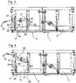
- the sliding flap device 17 has a sliding flap 21 as it moves between the closed position according to FIG Figure 1 and Figure 2 and the maximum opening position Figure 4 leading sliding guide arrangement 29, according to which close to both sliding flap side edges 31, 32 a plurality of mushroom-shaped or flat head rivet-shaped guideway elements 34 are arranged in a respective vertical row at intervals from one another with the formation of free spaces 36 therebetween, so that with their enlarged head sections they slide the flap 21 over the respective overlap adjacent sliding flap side edges 31, 32 by a few mm.
- the guide elements define a linear guide path 39 parallel to the sliding flap side edges 31, 32.
- the sliding guiding arrangement 29 designed in this way offers reliable guiding of the sliding flap 21 during its movement between the closed position and the open position.
- the sliding flap device 17 acts quasi self-cleaning due to the sliding guide arrangement 29 designed in this way, since any dirt on the sliding flap side edges 31, 32 is automatically wiped off on the guideway elements 34 when the sliding flap 21 moves, and therefore the sliding guide arrangement 29 does not adversely affect the sliding flap actuation in the area can accumulate.
- the guideway elements 34 are provided preassembled on carrier rails 37, 38.
- the carrier rails 37, 38 are screwed to the rear wall 7.
- the lever actuating mechanism 25 is a translating lever mechanism, which allows the sliding flap 21 to be applied with little effort and with a finely tuned path metering between the closed position Figure 1 and Figure 2 and the maximum opening position Figure 4 to postpone.
Landscapes
- Engineering & Computer Science (AREA)
- Transportation (AREA)
- Mechanical Engineering (AREA)
- Chemical & Material Sciences (AREA)
- Combustion & Propulsion (AREA)
- Support Devices For Sliding Doors (AREA)
- Wing Frames And Configurations (AREA)
- Power-Operated Mechanisms For Wings (AREA)
Priority Applications (1)
| Application Number | Priority Date | Filing Date | Title |
|---|---|---|---|
| PL18199065T PL3470263T3 (pl) | 2017-10-12 | 2018-10-08 | Burta zabudowy samowyładowczej dla pojazdu typu wywrotka, jak i wyposażony w nią pojazd typu wywrotka |
Applications Claiming Priority (1)
| Application Number | Priority Date | Filing Date | Title |
|---|---|---|---|
| DE102017218286.5A DE102017218286A1 (de) | 2017-10-12 | 2017-10-12 | Kippbrückenbordwand für ein Kipperfahrzeug sowie ein damit ausgerüstetes Kipperfahrzeug |
Publications (2)
| Publication Number | Publication Date |
|---|---|
| EP3470263A1 EP3470263A1 (de) | 2019-04-17 |
| EP3470263B1 true EP3470263B1 (de) | 2020-06-24 |
Family
ID=63798842
Family Applications (1)
| Application Number | Title | Priority Date | Filing Date |
|---|---|---|---|
| EP18199065.6A Active EP3470263B1 (de) | 2017-10-12 | 2018-10-08 | Kippbrückenbordwand für ein kipperfahrzeug sowie ein damit ausgerüstetes kipperfahrzeug |
Country Status (3)
| Country | Link |
|---|---|
| EP (1) | EP3470263B1 (pl) |
| DE (1) | DE102017218286A1 (pl) |
| PL (1) | PL3470263T3 (pl) |
Family Cites Families (10)
| Publication number | Priority date | Publication date | Assignee | Title |
|---|---|---|---|---|
| US2174197A (en) * | 1938-11-18 | 1939-09-26 | Ryan Patrick | Endgate for vehicles |
| US2635688A (en) * | 1951-12-10 | 1953-04-21 | Ralph R Bruning | Endgate |
| US3482876A (en) * | 1967-12-21 | 1969-12-09 | Tajon Inc | Vehicle discharge apparatus |
| DE2532400C2 (de) * | 1975-07-19 | 1985-08-01 | Conrad Fahrzeugbau Ferdinand Conrad KG, 2804 Lilienthal | Bewegbare, mindestens zwei Wandabschnitte umfassende Begrenzungswand für die Ladefläche eines Fahrzeuges |
| FR2537081A1 (fr) * | 1982-12-03 | 1984-06-08 | Venissieux Atel | Dispositif de fixation et d'escamotage de ridelles pour un vehicule de transport |
| JPH0924760A (ja) * | 1995-07-14 | 1997-01-28 | Nippon Furuhaafu Kk | テールゲートリフタの摺動構造 |
| US5890770A (en) * | 1997-11-26 | 1999-04-06 | Palmberg, Jr.; William C. | Dump vehicle with a positively controlled opening gate |
| US9211829B2 (en) * | 2013-06-11 | 2015-12-15 | Mac Trailer Manufacturing, Inc. | Locking door assembly for dump trailer and method of use |
| DE202013007557U1 (de) * | 2013-08-27 | 2013-10-17 | Huning Maschinenbau Gmbh | Fahrzeugaufbau für Nutzfahrzeuge |
| DE202016105059U1 (de) * | 2016-09-12 | 2017-04-25 | Stema Metalleichtbau Gmbh | Bordwandaufbau für die Ladefläche von Fahrzeugen, vorzugsweise von Anhängern als Dreiseitenkipper |
-
2017
- 2017-10-12 DE DE102017218286.5A patent/DE102017218286A1/de not_active Withdrawn
-
2018
- 2018-10-08 PL PL18199065T patent/PL3470263T3/pl unknown
- 2018-10-08 EP EP18199065.6A patent/EP3470263B1/de active Active
Non-Patent Citations (1)
| Title |
|---|
| None * |
Also Published As
| Publication number | Publication date |
|---|---|
| DE102017218286A1 (de) | 2019-04-18 |
| EP3470263A1 (de) | 2019-04-17 |
| PL3470263T3 (pl) | 2020-11-02 |
Similar Documents
| Publication | Publication Date | Title |
|---|---|---|
| DE3345122C2 (de) | Fahrzeugschiebedach | |
| EP0374421B1 (de) | Windabweiser für Schiebedächer, herausnehmbare Dachabschnitte oder dergleichen von Kraftfahrzeugen | |
| DE2648664C3 (de) | Verkleidung für ein Fahrzeugschiebedach mit Ausstellfunktion | |
| DE202013105032U1 (de) | Fahrzeug mit Abdeckvorrichtung für den Ladeaufbau | |
| DE69702305T2 (de) | Öffnungsvorrichtung für einen mit einer plane ausgerüsteten behälter | |
| DE102005033431B4 (de) | Vorrichtung zur Beeinflussung einer Luftströmung an einem öffnungsfähigen Fahrzeugdach | |
| EP1493601B1 (de) | Fahrzeugdach | |
| EP0720927B1 (de) | Fahrzeugdach mit einer zum Öffnen schwenkbaren Dachscheibe | |
| DE3843674C2 (pl) | ||
| DE2830192A1 (de) | Fahrzeugtuer, insbesondere fuer gewerbliche kraftfahrzeuge | |
| DE102013007876A1 (de) | Fahrzeugtüranordnung | |
| DE102010003932A1 (de) | Verdeckvorrichtung für einen Lastentransportbehälter | |
| EP1955932B1 (de) | Schließanordnung für einen Fahrzeugaufbau | |
| DE10145000C1 (de) | Seitenwand für einen Lastwagen, Lastanhänger, Sattelauflieger od. dgl. | |
| DE2658247A1 (de) | Foerderband-beschickungsluke fuer schuettgut mit verkoppelter streichplatte | |
| EP3470263A1 (de) | Kippbrückenbordwand für ein kipperfahrzeug sowie ein damit ausgerüstetes kipperfahrzeug | |
| DE10062156B4 (de) | Fahrzeugdach mit zwei hintereinander angeordneten, verschiebbaren Dachelementen | |
| EP2823994B1 (de) | Transportfahrzeug für Stückgut | |
| DE3333215C2 (pl) | ||
| DE307313C (pl) | ||
| DE102005026772B4 (de) | Hecktür für ein Fahrzeug mit einer Hecktürmechanik | |
| DE2532400A1 (de) | Bewegbare begrenzungswand fuer ein fahrzeug | |
| DE102008014496A1 (de) | Fahrzeugdach | |
| DE102005044173A1 (de) | Heckklappenanordnung eines Fahrzeugs mit rolloartiger Heckklappe | |
| DE2716094A1 (de) | Kratzerfoerderer |
Legal Events
| Date | Code | Title | Description |
|---|---|---|---|
| PUAI | Public reference made under article 153(3) epc to a published international application that has entered the european phase |
Free format text: ORIGINAL CODE: 0009012 |
|
| STAA | Information on the status of an ep patent application or granted ep patent |
Free format text: STATUS: THE APPLICATION HAS BEEN PUBLISHED |
|
| AK | Designated contracting states |
Kind code of ref document: A1 Designated state(s): AL AT BE BG CH CY CZ DE DK EE ES FI FR GB GR HR HU IE IS IT LI LT LU LV MC MK MT NL NO PL PT RO RS SE SI SK SM TR |
|
| AX | Request for extension of the european patent |
Extension state: BA ME |
|
| STAA | Information on the status of an ep patent application or granted ep patent |
Free format text: STATUS: REQUEST FOR EXAMINATION WAS MADE |
|
| 17P | Request for examination filed |
Effective date: 20190916 |
|
| RBV | Designated contracting states (corrected) |
Designated state(s): AL AT BE BG CH CY CZ DE DK EE ES FI FR GB GR HR HU IE IS IT LI LT LU LV MC MK MT NL NO PL PT RO RS SE SI SK SM TR |
|
| GRAP | Despatch of communication of intention to grant a patent |
Free format text: ORIGINAL CODE: EPIDOSNIGR1 |
|
| STAA | Information on the status of an ep patent application or granted ep patent |
Free format text: STATUS: GRANT OF PATENT IS INTENDED |
|
| INTG | Intention to grant announced |
Effective date: 20200211 |
|
| GRAS | Grant fee paid |
Free format text: ORIGINAL CODE: EPIDOSNIGR3 |
|
| GRAA | (expected) grant |
Free format text: ORIGINAL CODE: 0009210 |
|
| STAA | Information on the status of an ep patent application or granted ep patent |
Free format text: STATUS: THE PATENT HAS BEEN GRANTED |
|
| AK | Designated contracting states |
Kind code of ref document: B1 Designated state(s): AL AT BE BG CH CY CZ DE DK EE ES FI FR GB GR HR HU IE IS IT LI LT LU LV MC MK MT NL NO PL PT RO RS SE SI SK SM TR |
|
| REG | Reference to a national code |
Ref country code: GB Ref legal event code: FG4D Free format text: NOT ENGLISH |
|
| REG | Reference to a national code |
Ref country code: CH Ref legal event code: EP |
|
| REG | Reference to a national code |
Ref country code: AT Ref legal event code: REF Ref document number: 1283562 Country of ref document: AT Kind code of ref document: T Effective date: 20200715 |
|
| REG | Reference to a national code |
Ref country code: DE Ref legal event code: R096 Ref document number: 502018001741 Country of ref document: DE |
|
| REG | Reference to a national code |
Ref country code: IE Ref legal event code: FG4D Free format text: LANGUAGE OF EP DOCUMENT: GERMAN |
|
| PG25 | Lapsed in a contracting state [announced via postgrant information from national office to epo] |
Ref country code: GR Free format text: LAPSE BECAUSE OF FAILURE TO SUBMIT A TRANSLATION OF THE DESCRIPTION OR TO PAY THE FEE WITHIN THE PRESCRIBED TIME-LIMIT Effective date: 20200925 Ref country code: NO Free format text: LAPSE BECAUSE OF FAILURE TO SUBMIT A TRANSLATION OF THE DESCRIPTION OR TO PAY THE FEE WITHIN THE PRESCRIBED TIME-LIMIT Effective date: 20200924 Ref country code: LT Free format text: LAPSE BECAUSE OF FAILURE TO SUBMIT A TRANSLATION OF THE DESCRIPTION OR TO PAY THE FEE WITHIN THE PRESCRIBED TIME-LIMIT Effective date: 20200624 Ref country code: FI Free format text: LAPSE BECAUSE OF FAILURE TO SUBMIT A TRANSLATION OF THE DESCRIPTION OR TO PAY THE FEE WITHIN THE PRESCRIBED TIME-LIMIT Effective date: 20200624 Ref country code: SE Free format text: LAPSE BECAUSE OF FAILURE TO SUBMIT A TRANSLATION OF THE DESCRIPTION OR TO PAY THE FEE WITHIN THE PRESCRIBED TIME-LIMIT Effective date: 20200624 |
|
| REG | Reference to a national code |
Ref country code: LT Ref legal event code: MG4D |
|
| PG25 | Lapsed in a contracting state [announced via postgrant information from national office to epo] |
Ref country code: BG Free format text: LAPSE BECAUSE OF FAILURE TO SUBMIT A TRANSLATION OF THE DESCRIPTION OR TO PAY THE FEE WITHIN THE PRESCRIBED TIME-LIMIT Effective date: 20200924 Ref country code: RS Free format text: LAPSE BECAUSE OF FAILURE TO SUBMIT A TRANSLATION OF THE DESCRIPTION OR TO PAY THE FEE WITHIN THE PRESCRIBED TIME-LIMIT Effective date: 20200624 Ref country code: LV Free format text: LAPSE BECAUSE OF FAILURE TO SUBMIT A TRANSLATION OF THE DESCRIPTION OR TO PAY THE FEE WITHIN THE PRESCRIBED TIME-LIMIT Effective date: 20200624 Ref country code: HR Free format text: LAPSE BECAUSE OF FAILURE TO SUBMIT A TRANSLATION OF THE DESCRIPTION OR TO PAY THE FEE WITHIN THE PRESCRIBED TIME-LIMIT Effective date: 20200624 |
|
| REG | Reference to a national code |
Ref country code: NL Ref legal event code: MP Effective date: 20200624 |
|
| PG25 | Lapsed in a contracting state [announced via postgrant information from national office to epo] |
Ref country code: AL Free format text: LAPSE BECAUSE OF FAILURE TO SUBMIT A TRANSLATION OF THE DESCRIPTION OR TO PAY THE FEE WITHIN THE PRESCRIBED TIME-LIMIT Effective date: 20200624 Ref country code: NL Free format text: LAPSE BECAUSE OF FAILURE TO SUBMIT A TRANSLATION OF THE DESCRIPTION OR TO PAY THE FEE WITHIN THE PRESCRIBED TIME-LIMIT Effective date: 20200624 |
|
| PG25 | Lapsed in a contracting state [announced via postgrant information from national office to epo] |
Ref country code: SM Free format text: LAPSE BECAUSE OF FAILURE TO SUBMIT A TRANSLATION OF THE DESCRIPTION OR TO PAY THE FEE WITHIN THE PRESCRIBED TIME-LIMIT Effective date: 20200624 Ref country code: RO Free format text: LAPSE BECAUSE OF FAILURE TO SUBMIT A TRANSLATION OF THE DESCRIPTION OR TO PAY THE FEE WITHIN THE PRESCRIBED TIME-LIMIT Effective date: 20200624 Ref country code: IT Free format text: LAPSE BECAUSE OF FAILURE TO SUBMIT A TRANSLATION OF THE DESCRIPTION OR TO PAY THE FEE WITHIN THE PRESCRIBED TIME-LIMIT Effective date: 20200624 Ref country code: EE Free format text: LAPSE BECAUSE OF FAILURE TO SUBMIT A TRANSLATION OF THE DESCRIPTION OR TO PAY THE FEE WITHIN THE PRESCRIBED TIME-LIMIT Effective date: 20200624 Ref country code: PT Free format text: LAPSE BECAUSE OF FAILURE TO SUBMIT A TRANSLATION OF THE DESCRIPTION OR TO PAY THE FEE WITHIN THE PRESCRIBED TIME-LIMIT Effective date: 20201026 Ref country code: ES Free format text: LAPSE BECAUSE OF FAILURE TO SUBMIT A TRANSLATION OF THE DESCRIPTION OR TO PAY THE FEE WITHIN THE PRESCRIBED TIME-LIMIT Effective date: 20200624 |
|
| PG25 | Lapsed in a contracting state [announced via postgrant information from national office to epo] |
Ref country code: SK Free format text: LAPSE BECAUSE OF FAILURE TO SUBMIT A TRANSLATION OF THE DESCRIPTION OR TO PAY THE FEE WITHIN THE PRESCRIBED TIME-LIMIT Effective date: 20200624 Ref country code: IS Free format text: LAPSE BECAUSE OF FAILURE TO SUBMIT A TRANSLATION OF THE DESCRIPTION OR TO PAY THE FEE WITHIN THE PRESCRIBED TIME-LIMIT Effective date: 20201024 |
|
| REG | Reference to a national code |
Ref country code: DE Ref legal event code: R097 Ref document number: 502018001741 Country of ref document: DE |
|
| PG25 | Lapsed in a contracting state [announced via postgrant information from national office to epo] |
Ref country code: DK Free format text: LAPSE BECAUSE OF FAILURE TO SUBMIT A TRANSLATION OF THE DESCRIPTION OR TO PAY THE FEE WITHIN THE PRESCRIBED TIME-LIMIT Effective date: 20200624 |
|
| PLBE | No opposition filed within time limit |
Free format text: ORIGINAL CODE: 0009261 |
|
| STAA | Information on the status of an ep patent application or granted ep patent |
Free format text: STATUS: NO OPPOSITION FILED WITHIN TIME LIMIT |
|
| 26N | No opposition filed |
Effective date: 20210325 |
|
| PG25 | Lapsed in a contracting state [announced via postgrant information from national office to epo] |
Ref country code: MC Free format text: LAPSE BECAUSE OF FAILURE TO SUBMIT A TRANSLATION OF THE DESCRIPTION OR TO PAY THE FEE WITHIN THE PRESCRIBED TIME-LIMIT Effective date: 20200624 Ref country code: LU Free format text: LAPSE BECAUSE OF NON-PAYMENT OF DUE FEES Effective date: 20201008 |
|
| REG | Reference to a national code |
Ref country code: BE Ref legal event code: MM Effective date: 20201031 |
|
| PG25 | Lapsed in a contracting state [announced via postgrant information from national office to epo] |
Ref country code: SI Free format text: LAPSE BECAUSE OF FAILURE TO SUBMIT A TRANSLATION OF THE DESCRIPTION OR TO PAY THE FEE WITHIN THE PRESCRIBED TIME-LIMIT Effective date: 20200624 Ref country code: BE Free format text: LAPSE BECAUSE OF NON-PAYMENT OF DUE FEES Effective date: 20201031 |
|
| PG25 | Lapsed in a contracting state [announced via postgrant information from national office to epo] |
Ref country code: IE Free format text: LAPSE BECAUSE OF NON-PAYMENT OF DUE FEES Effective date: 20201008 |
|
| REG | Reference to a national code |
Ref country code: CH Ref legal event code: PL |
|
| PG25 | Lapsed in a contracting state [announced via postgrant information from national office to epo] |
Ref country code: TR Free format text: LAPSE BECAUSE OF FAILURE TO SUBMIT A TRANSLATION OF THE DESCRIPTION OR TO PAY THE FEE WITHIN THE PRESCRIBED TIME-LIMIT Effective date: 20200624 Ref country code: MT Free format text: LAPSE BECAUSE OF FAILURE TO SUBMIT A TRANSLATION OF THE DESCRIPTION OR TO PAY THE FEE WITHIN THE PRESCRIBED TIME-LIMIT Effective date: 20200624 Ref country code: CY Free format text: LAPSE BECAUSE OF FAILURE TO SUBMIT A TRANSLATION OF THE DESCRIPTION OR TO PAY THE FEE WITHIN THE PRESCRIBED TIME-LIMIT Effective date: 20200624 |
|
| PG25 | Lapsed in a contracting state [announced via postgrant information from national office to epo] |
Ref country code: MK Free format text: LAPSE BECAUSE OF FAILURE TO SUBMIT A TRANSLATION OF THE DESCRIPTION OR TO PAY THE FEE WITHIN THE PRESCRIBED TIME-LIMIT Effective date: 20200624 |
|
| PG25 | Lapsed in a contracting state [announced via postgrant information from national office to epo] |
Ref country code: LI Free format text: LAPSE BECAUSE OF NON-PAYMENT OF DUE FEES Effective date: 20211031 Ref country code: CH Free format text: LAPSE BECAUSE OF NON-PAYMENT OF DUE FEES Effective date: 20211031 |
|
| GBPC | Gb: european patent ceased through non-payment of renewal fee |
Effective date: 20221008 |
|
| PG25 | Lapsed in a contracting state [announced via postgrant information from national office to epo] |
Ref country code: GB Free format text: LAPSE BECAUSE OF NON-PAYMENT OF DUE FEES Effective date: 20221008 |
|
| PGFP | Annual fee paid to national office [announced via postgrant information from national office to epo] |
Ref country code: PL Payment date: 20250926 Year of fee payment: 8 |
|
| PGFP | Annual fee paid to national office [announced via postgrant information from national office to epo] |
Ref country code: DE Payment date: 20250929 Year of fee payment: 8 |
|
| PGFP | Annual fee paid to national office [announced via postgrant information from national office to epo] |
Ref country code: AT Payment date: 20251022 Year of fee payment: 8 |
|
| PGFP | Annual fee paid to national office [announced via postgrant information from national office to epo] |
Ref country code: FR Payment date: 20251030 Year of fee payment: 8 |
|
| PGFP | Annual fee paid to national office [announced via postgrant information from national office to epo] |
Ref country code: CZ Payment date: 20250930 Year of fee payment: 8 |