EP3469968A1 - Elektromotorisch betriebene küchenmaschine mit einer mahlvorrichtung - Google Patents
Elektromotorisch betriebene küchenmaschine mit einer mahlvorrichtung Download PDFInfo
- Publication number
- EP3469968A1 EP3469968A1 EP18198610.0A EP18198610A EP3469968A1 EP 3469968 A1 EP3469968 A1 EP 3469968A1 EP 18198610 A EP18198610 A EP 18198610A EP 3469968 A1 EP3469968 A1 EP 3469968A1
- Authority
- EP
- European Patent Office
- Prior art keywords
- grinding
- vessel
- food processor
- grinder
- electric motor
- Prior art date
- Legal status (The legal status is an assumption and is not a legal conclusion. Google has not performed a legal analysis and makes no representation as to the accuracy of the status listed.)
- Granted
Links
Images



Classifications
-
- A—HUMAN NECESSITIES
- A47—FURNITURE; DOMESTIC ARTICLES OR APPLIANCES; COFFEE MILLS; SPICE MILLS; SUCTION CLEANERS IN GENERAL
- A47J—KITCHEN EQUIPMENT; COFFEE MILLS; SPICE MILLS; APPARATUS FOR MAKING BEVERAGES
- A47J43/00—Implements for preparing or holding food, not provided for in other groups of this subclass
- A47J43/04—Machines for domestic use not covered elsewhere, e.g. for grinding, mixing, stirring, kneading, emulsifying, whipping or beating foodstuffs, e.g. power-driven
- A47J43/046—Machines for domestic use not covered elsewhere, e.g. for grinding, mixing, stirring, kneading, emulsifying, whipping or beating foodstuffs, e.g. power-driven with tools driven from the bottom side
-
- A—HUMAN NECESSITIES
- A47—FURNITURE; DOMESTIC ARTICLES OR APPLIANCES; COFFEE MILLS; SPICE MILLS; SUCTION CLEANERS IN GENERAL
- A47J—KITCHEN EQUIPMENT; COFFEE MILLS; SPICE MILLS; APPARATUS FOR MAKING BEVERAGES
- A47J42/00—Coffee mills; Spice mills
- A47J42/02—Coffee mills; Spice mills having grinding cones
- A47J42/10—Grinding cones
-
- A—HUMAN NECESSITIES
- A47—FURNITURE; DOMESTIC ARTICLES OR APPLIANCES; COFFEE MILLS; SPICE MILLS; SUCTION CLEANERS IN GENERAL
- A47J—KITCHEN EQUIPMENT; COFFEE MILLS; SPICE MILLS; APPARATUS FOR MAKING BEVERAGES
- A47J43/00—Implements for preparing or holding food, not provided for in other groups of this subclass
- A47J43/04—Machines for domestic use not covered elsewhere, e.g. for grinding, mixing, stirring, kneading, emulsifying, whipping or beating foodstuffs, e.g. power-driven
-
- A—HUMAN NECESSITIES
- A47—FURNITURE; DOMESTIC ARTICLES OR APPLIANCES; COFFEE MILLS; SPICE MILLS; SUCTION CLEANERS IN GENERAL
- A47J—KITCHEN EQUIPMENT; COFFEE MILLS; SPICE MILLS; APPARATUS FOR MAKING BEVERAGES
- A47J42/00—Coffee mills; Spice mills
- A47J42/02—Coffee mills; Spice mills having grinding cones
- A47J42/06—Coffee mills; Spice mills having grinding cones mechanically driven
-
- A—HUMAN NECESSITIES
- A47—FURNITURE; DOMESTIC ARTICLES OR APPLIANCES; COFFEE MILLS; SPICE MILLS; SUCTION CLEANERS IN GENERAL
- A47J—KITCHEN EQUIPMENT; COFFEE MILLS; SPICE MILLS; APPARATUS FOR MAKING BEVERAGES
- A47J43/00—Implements for preparing or holding food, not provided for in other groups of this subclass
- A47J43/04—Machines for domestic use not covered elsewhere, e.g. for grinding, mixing, stirring, kneading, emulsifying, whipping or beating foodstuffs, e.g. power-driven
- A47J43/07—Parts or details, e.g. mixing tools, whipping tools
-
- A—HUMAN NECESSITIES
- A47—FURNITURE; DOMESTIC ARTICLES OR APPLIANCES; COFFEE MILLS; SPICE MILLS; SUCTION CLEANERS IN GENERAL
- A47J—KITCHEN EQUIPMENT; COFFEE MILLS; SPICE MILLS; APPARATUS FOR MAKING BEVERAGES
- A47J43/00—Implements for preparing or holding food, not provided for in other groups of this subclass
- A47J43/04—Machines for domestic use not covered elsewhere, e.g. for grinding, mixing, stirring, kneading, emulsifying, whipping or beating foodstuffs, e.g. power-driven
- A47J43/07—Parts or details, e.g. mixing tools, whipping tools
- A47J43/0716—Parts or details, e.g. mixing tools, whipping tools for machines with tools driven from the lower side
-
- A—HUMAN NECESSITIES
- A47—FURNITURE; DOMESTIC ARTICLES OR APPLIANCES; COFFEE MILLS; SPICE MILLS; SUCTION CLEANERS IN GENERAL
- A47J—KITCHEN EQUIPMENT; COFFEE MILLS; SPICE MILLS; APPARATUS FOR MAKING BEVERAGES
- A47J42/00—Coffee mills; Spice mills
- A47J42/02—Coffee mills; Spice mills having grinding cones
Definitions
- the invention relates to an electric motor driven food processor with a base unit having an electric motor and a connectable to the base device preparation vessel, in which a rotatably driven by the electric motor rotary member projects, with the rotation element, a grinding element is connected, which content with a Mahl Complex held on the preparation vessel Milling vessel forms a grinder.
- Electric motor driven kitchen machines with a base unit and connectable to the base unit preparation vessel are well known in the art.
- the pamphlets WO 2003/075727 A1 and EP 1 269 898 B1 disclose such electromotive kitchen machines, which are designed as combined cooking-mixing devices.
- the preparation vessel is a stirrer vessel, through the bottom of the vessel a rotary element protrudes into the stirrer vessel. On the rotation element, a knife set with a plurality of blades is arranged, which serve for the mincing of food.
- the CN 204909176 U a food processor, which has a grinding element connected to the rotation element, which forms a grinder with a grinding area of a grinding vessel.
- the grinding element is connected to the rotation element via a coupling element having at least one elastic portion.
- the coupling element may be a partial region of the grinding element or a partial region of the rotating element.
- the coupling element is a separate element to both the refining element and the rotating element.
- the coupling element is used to connect the grinding element to the rotating element and at the same time - by forming an elastic portion - as a flexible compensation element to compensate for an axial inclination of the grinding element in the grinding vessel and / or a radial displacement of the grinding element relative to the grinding vessel.
- impacts of the grinder are damped, which occur in the crushing of the starting materials.
- the food processor has a grinding element which can be connected to the rotation element and which forms a grinding mechanism with a grinding region of a grinding vessel held on the preparation vessel.
- the grinder which can be connected to the drive of the food processor, makes it possible, as a variably usable accessory of the food processor, to prepare dishes from starting products which first have to be ground.
- the starting materials may be, for example, cereal grains, coffee beans or spice grains.
- the grinder has a grinding area of the grinding vessel, which is immovably connected to the preparation vessel, so that the rotational movement of the rotating element does not transfer to the grinding vessel.
- the rotation element is relative to the preparation vessel and thus also to the Grinding vessel rotatable so that the grinding element fixed to the rotating element rotates relative to the grinding area of the grinding vessel and thereby grinding in the gap between the grinding area and grinding element located starting materials.
- the grinding area is preferably a partial area of an inner wall of the grinding vessel, on which stored starting products can flow and where they can be comminuted by the grinding element.
- the grinding element is connected via the rotary member directly to a drive shaft of the electric motor. Thus, a direct drive is possible.
- a gentle crushing grinding is made possible, in which the starting material heats only slightly and a more uniform grinding result is obtained.
- the grinder is adjustable with respect to the distance between the grinding element and the grinding area, the grinding degree can be finely adjusted.
- the grinder can be designed for example spices with a gram accurate fine dosage. Overall, the integration of a grinder in the kitchen machine thus eliminates a separate coffee grinder, flour mill or other mill.
- the grinding element protrude into the grinding vessel, wherein the grinding area surrounds the grinding element in the circumferential direction, so that the grinding element rotates during a grinding process within the grinding area.
- the grinding element is at the same time, so that a partial region of the grinding vessel forms the grinding mechanism.
- the comminuted millbase can then be collected first in a separate chamber of the grinding vessel or alternatively be discharged directly into the preparation vessel, so that the millbase can be added directly to a food to be prepared, for example, cereals in a dough to be stirred, pepper in a stew and like.
- a food preparation the material to be ground could furthermore be fed directly into a food heated to a preparation temperature by means of a heating device associated with the preparation vessel.
- the grinding vessel is arranged in the preparation vessel. It can be provided in particular that the grinding vessel attached to a wall or a lid of the preparation vessel, for example screwed there is. In an arrangement on a lid of the preparation vessel may be provided in particular that the grinding vessel is closed by the lid, so that the user can not hurt himself on the grinder.
- the grinding vessel may, for example, have outwardly projecting projections which can be guided through boreholes in the lid of the preparation vessel and fixed there. Due to the arrangement of the grinding vessel and thus also of the grinder within the preparation vessel, the proportion of exiting sound is very low.
- the starting materials can not be thrown against the inner wall of the preparation vessel, and on the other hand, the grinder is doubly surrounded by a wall, namely on the one hand with the wall of the grinding vessel and the other with the wall of the preparation vessel. Further, when the connection between the grinding vessel and the preparation vessel is made via a sound-deadening member, the sound emission can be further reduced.
- the grinding vessel can also be placed on the preparation vessel, d. H. be arranged outside the preparation vessel.
- the rotating element of the food processor is extended by means of a drive shaft through the preparation vessel and preferably emerges from the preparation vessel in the region of a lid.
- the rotary element forms the drive for the external grinder.
- the drive shaft can also be brought up out of the preparation vessel and drive there further accessories, such as a lemon / orange squeezer, a meat grinder, a pasta machine, a can opener, a vegetable press and the like.
- the grinding element can be separably connected to the rotation element.
- the grinding element is a separate element, which can be particularly easily connected to the rotation element or separated from it as needed. It is not necessary to completely remove the rotating element having the grinding element from a rotary bearing and to replace it with another rotary element. Instead, only the refining element can be separated as an additional part from the rotation element, so that the rotation element can always remain in the food processor, namely in the rotation bearing. This saves time when using different accessories of the food processor.
- the coupling element has a spring element.
- the spring element has a movement margin both parallel to a longitudinal extent of a rotation axis of the rotation element and perpendicular thereto.
- a flexible material area be the coupling element.
- the spring element is designed in the manner of a resilient strap or ring whose spring plane is oriented parallel to the axis of rotation of the rotary member.
- the spring element may be a resilient plastic ring, which is connected on the one hand with the refining element and on the other hand with the rotary member or connectable.
- the rotation element has a knife set with a plurality of knives.
- the rotation element according to this embodiment simultaneously represents the drive shaft for a set of blades, which usually serves for the comminution or stirring of food.
- the rotating element can thus drive on the one hand a knife set and on the other hand the grinding element, so that several working steps can be carried out simultaneously within the food processor, namely, for example, stirring a food in the preparation vessel and, on the other hand, grinding a starting product located inside the grinding vessel.
- the milled ground material can be fed directly into the prepared food within the preparation vessel, namely for example by an outlet on preferably a bottom side of the grinding vessel.
- the coupling element has a driver element for detachable connection of the coupling element to the rotary element, wherein the driver element can be fixed in particular between adjacent blades of a blade set.
- the driver element may be a forked or hook-shaped attachment whose prongs are in contact with the knives of the knife set, in particular engage between the knives.
- the connection between the driver element and the rotary element is advantageously designed so that it keeps independent during operation of the grinder, especially when increasing the level within the preparation vessel.
- the grinding vessel has a plurality of separate chambers for receiving raw materials to be ground and / or for receiving ground material.
- the grinder is located in the grinding housing containing and supplying the starting products.
- the grinding vessel is preferably open at the top or closed by a lid.
- a chamber system may be provided with a plurality of chambers, which can be opened or closed individually or jointly, automatically or manually.
- certain speed ranges or modes of the electric motor driving the rotary element can be blocked if a detection device of the food processor recognizes a presence of the grinding element and / or grinding vessel inside the food processor.
- the detection device may, for example, function mechanically, magnetically or in another way.
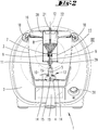
- FIG. 1 shows an electric motor driven food processor 1, which is designed here as a combined cooking-mixing device.
- the food processor 1 has a base unit 2, in which a preparation vessel 3 is inserted.
- the preparation vessel 3 is associated with a heating device, not shown, here preferably integrated into the vessel bottom of the preparation vessel 3.
- a rotary bearing 4 is also used, which rotatably supports the rotary element 5.
- the rotary element 5 is connected to a knife set 13, which has a plurality of knives 14.
- Connected to the knife set 13 is furthermore a coupling element 10 for a grinding element 6 of a grinder 9 (see FIG. 2 ).
- the coupling element 10 has a driver element 15, which engages with wing-like end regions between the blades 14 of the blade set 13.
- the coupling element 10 further comprises a spring element 11, which connects the coupling element 10 resiliently with the grinding element 6 of the grinder 9.
- the grinding element 6 is arranged in a grinding vessel 8, the inner wall of which provides a grinding area 7 for interaction with the grinding element 6.
- the grinding element 6 is frusto-conical and rotates, driven by the rotation element 5, within the cylindrical Mahl Symposiumes 7, wherein grinding element 6 and grinding area 7 cooperate as grinder 9.
- the preparation vessel 3 is further associated with a lid 16, which is connected by means of sealing rollers 18 fluid-tight manner with the preparation vessel 3.
- the preparation vessel 3 further has a handle 17 for gripping the preparation vessel 3 by a user.
- the base unit 2 of the food processor 1 has a display 19 for displaying status parameters of the food processor 1, recipe suggestions, current parameters of the preparation material in the preparation vessel 3 and the like.
- the lid 16 of the preparation vessel 3 has here, for example, an opening through which a portion of the grinding vessel 8 protrudes and in position, d. H.
- a container lid 28 of the grinding vessel 8 projects through a drive shaft 21 through which has a rotationally fixed connection to the grinding element 6 and thus also to the rotary member 5 and thus also rotates upon rotation of the rotary member 5.
- FIG. 2 shows a longitudinal section through the connected to the base unit 2 of the food processor 1 preparation vessel 3.
- the longitudinal section is along the axis of rotation 12 of the rotary member 5.
- Mahlgefäß 8 is in FIG. 3 further shown enlarged.
- the rotary element 5 is rotatable by means of the electric motor of the food processor 1.
- the grinding element 6 rotates with rotation of the rotary member 5 with.
- the grinding element 6 forms together with the cylindrical grinding area 7 of the grinding vessel 8 a grinder 9.
- the grinder 9 is designed here as a conical grinder and is located within the grinding vessel 8, which has a chamber 22 for a starting material to be ground and a chamber 23 for the means of Grinder 9 has ground regrind. In the area of the grinder 9 is located between the chamber 22 and the chamber 23 has an opening 24 (see FIG. 3 ), through which the ground material can pass from the chamber 22 into the chamber 23.
- the chamber 23 has a bottom 29 of the grinding vessel 8, which is connected via a screw with the grinding vessel 8, so that the chamber 23 can be emptied from the grinding vessel 8 on separation of the bottom 29. Due to the funnel-shaped design of the chamber 22, the starting product to be ground slips always into the grinding area 7 of the chamber 22, so that the starting product is continuously fed into the grinder 9 and can be ground there.
- the coupling element 10 engages with the fork-shaped driver element 15 between the blades 14 of the blade set 13.
- the spring element 11 of the coupling element 10 is both an element parallel to the axis of rotation 12 and perpendicular to elastic element made of metal or plastic, which on the one hand prevents an axial inclination of the grinder 9 in the grinding vessel 8, and on the other hand, a radial displacement of the grinding vessel 8 within of the preparation vessel 3.
- the spring element 11 damps impacts on the rotary element 5, which may occur due to the grinding action of the grinder 9.
- the grinding vessel 8 is fastened to the preparation vessel 3.
- the attachment can be done either on a wall of the preparation vessel 3 or on the lid 16 of the preparation vessel 3.
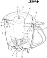
- Figure 4 shows, for example, an attachment of the grinding vessel 8 on the lid 16.
- the grinding vessel 8 carries on the outside two fastening arms 25 which engage in receptacles 26 which are formed on projections 27 of the lid 16.
- the receptacles 26 receive the attachment arms 25 in the manner of a bayonet closure. If this compound is additionally equipped with a sound-damping element, a sound transmission from the grinder 9 of the grinding vessel 8 can be reduced to the preparation vessel 3.
- the grinding vessel 8 is arranged completely above the preparation vessel 3 and is therefore located completely outside the preparation vessel 3.
- the arrangement of the grinding vessel 8 within the preparation vessel 3 is advantageous, since then an additional sound insulation is created by the surrounding preparation vessel 3.
- a drive shaft 21 connected to the refining member 6 and the rotation member 5 projecting outwardly through the vessel lid 28 may be used to drive a juicer, a meat grinder, a pasta maker, a can opener, a vegetable press or others.
- FIG. 5 shows an exploded view with, viewed along the axis of rotation 12 from top to bottom, the lid 16, an adapter ring 30 for the lid 16, which adapter ring 30 provides the projections 27 for receiving the mounting arms 25 of the grinding vessel 8, the grinding vessel 8, the coupling element 10 having the spring element 11 and the driver element 15 and the rotary member 5 which carries the blade set 13.
- an operation of the grinder 9 is also possible when a user is preparing a food with the food processor 1.
- grain can be ground in the grinding jar 7 while the set of knives 13 is currently mixing ingredients in the preparation jar 3 into a dough.
- the grinder 9, for example, at the same time grind peppercorns and add them to a heated in the preparation vessel 3 stew. So that the ground material can pass directly from the chamber 23 into the preparation vessel 3, the bottom 29 is either removable or alternatively equipped with openings (not shown) through which the ground material from the chamber 23 can fall into the preparation vessel 3.
Landscapes
- Engineering & Computer Science (AREA)
- Mechanical Engineering (AREA)
- Food Science & Technology (AREA)
- Food-Manufacturing Devices (AREA)
- Crushing And Pulverization Processes (AREA)
Abstract
Description
- Die Erfindung betrifft eine elektromotorisch betriebene Küchenmaschine mit einem einen Elektromotor aufweisenden Basisgerät und einem mit dem Basisgerät verbindbaren Zubereitungsgefäß, in welches ein mittels des Elektromotors rotierend antreibbares Rotationselement ragt, wobei mit dem Rotationselement ein Mahlelement verbindbar ist, welches mit einem Mahlbereich eines an dem Zubereitungsgefäß gehalterten Mahlgefäßes ein Mahlwerk bildet.
- Elektromotorisch betriebene Küchenmaschinen mit einem Basisgerät und einem mit dem Basisgerät verbindbaren Zubereitungsgefäß sind im Stand der Technik hinreichend bekannt.
- Die Druckschriften
WO 2003/075727 A1 undEP 1 269 898 B1 offenbaren derartige elektromotorische Küchenmaschinen, welche als kombinierte Koch-Mix-Geräte ausgebildet sind. Das Zubereitungsgefäß ist ein Rührgefäß, durch dessen Gefäßboden ein Rotationselement in das Rührgefäß ragt. An dem Rotationselement ist ein Messersatz mit einer Mehrzahl von Messern angeordnet, die zum Zerkleinern von Speisen dienen. - Des Weiteren offenbart die
CN 204909176 U eine Küchenmaschine, welche ein mit dem Rotationselement verbundenes Mahlelement aufweist, welches mit einem Mahlbereich eines Mahlgefäßes ein Mahlwerk bildet. - Ausgehend davon ist es Aufgabe der Erfindung, das Mahlwerk der Küchenmaschine vorteilhaft weiterzubilden.
- Zur Lösung der vorgenannten Aufgabe wird vorgeschlagen, dass das Mahlelement über ein zumindest einen elastischen Teilbereich aufweisendes Kupplungselement mit dem Rotationselement verbunden ist. Das Kupplungselement kann ein Teilbereich des Mahlelementes oder ein Teilbereich des Rotationselementes sein. Darüber hinaus ist es möglich, dass das Kupplungselement ein sowohl zu dem Mahlelement, als auch zu dem Rotationselement separates Element ist. Das Kupplungselement dient zur Verbindung des Mahlelementes mit dem Rotationselement und gleichzeitig - durch die Ausbildung eines elastischen Teilbereiches - als flexibles Ausgleichselement, um eine axiale Neigung des Mahlelementes in dem Mahlgefäß und/oder eine radiale Verschiebung des Mahlelementes relativ zu dem Mahlgefäß auszugleichen. Des Weiteren werden schließlich auch Schläge des Mahlwerkes gedämpft, die bei dem Zerkleinern der Ausgangsprodukte auftreten.
- Die Küchenmaschine weist ein mit dem Rotationselement verbindbares Mahlelement auf, welches mit einem Mahlbereich eines an dem Zubereitungsgefäß gehalterten Mahlgefäßes ein Mahlwerk bildet. Das mit dem Antrieb der Küchenmaschine verbindbare Mahlwerk ermöglicht als variabel verwendbares Zubehör der Küchenmaschine eine Zubereitung von Gerichten aus Ausgangsprodukten, die zunächst gemahlen werden müssen. Die Ausgangsprodukte können zum Beispiel Getreidekörner, Kaffeebohnen oder Gewürzkörner sein. Das Mahlwerk weist einen Mahlbereich des Mahlgefäßes auf, welches unbeweglich mit dem Zubereitungsgefäß verbunden wird, so dass sich die Rotationsbewegung des Rotationselementes nicht auf das Mahlgefäß überträgt. Das Rotationselement ist relativ zu dem Zubereitungsgefäß und damit auch zu dem Mahlgefäß rotierbar, so dass das an dem Rotationselement befestigte Mahlelement relativ zu dem Mahlbereich des Mahlgefäßes rotiert und dabei in dem Zwischenraum zwischen Mahlbereich und Mahlelement befindliche Ausgangsprodukte mahlt. Der Mahlbereich ist vorzugsweise ein Teilbereich einer Innenwandung des Mahlgefäßes, an welcher bevorratete Ausgangsprodukte nachströmen und dort von dem Mahlelement zerkleinert werden können. Das Mahlelement ist über das Rotationselement direkt mit einer Antriebswelle des Elektromotors verbunden. Somit ist ein Direktantrieb ermöglicht. Des Weiteren wird, im Gegensatz zum Zerhacken des Ausgangsproduktes mittels beispielsweise eines Messersatzes, ein schonendes Quetschmahlen ermöglicht, bei welchem sich das Ausgangsprodukt nur geringfügig erwärmt und ein gleichmäßigeres Mahlergebnis erhält. Sofern das Mahlwerk in Bezug auf den Abstand zwischen dem Mahlelement und dem Mahlbereich einstellbar ist, lässt sich der Mahlgrad feinjustieren. Das Mahlwerk kann für beispielsweise Gewürze mit einer grammgenauen Feindosierung ausgebildet sein. Insgesamt entfällt durch die Integration eines Mahlwerkes in die Küchenmaschine somit eine separate Kaffeemühle, Getreidemühle oder sonstige Mühle.
- Insbesondere wird vorgeschlagen, dass das Mahlelement in das Mahlgefäß hineinragt, wobei der Mahlbereich das Mahlelement in Umfangsrichtung umgibt, so dass das Mahlelement bei einem Mahlvorgang innerhalb des Mahlbereiches rotiert. In dem die Ausgangsprodukte aufnehmenden Mahlgefäß befindet sich gleichzeitig das Mahlelement, so dass ein Teilbereich des Mahlgefäßes das Mahlwerk bildet. Insbesondere empfiehlt es sich, das Mahlwerk nach der Art einer üblichen Handkaffeemühle, insbesondere als Kegelmahlwerk auszugestalten, bei welcher ein konisches Mahlelement von einem zylindrischen Mahlbereich umgeben ist. Bei Betrieb des Mahlwerkes rotiert das Mahlelement innerhalb des zylindrischen Mahlbereiches, so dass die Zähne des Mahlelementes und des Mahlbereiches mechanisch auf die dazwischen befindlichen Ausgangsprodukte, beispielsweise Getreidekörner oder Kaffeebohnen, einwirken. Das zerkleinerte Mahlgut kann dann zunächst in einer separaten Kammer des Mahlgefäßes gesammelt werden oder alternativ auch direkt in das Zubereitungsgefäß ausgelassen werden, so dass das Mahlgut beispielsweise direkt einer zuzubereitenden Speise zugegeben werden kann, beispielsweise Getreide in einen zu rührenden Teig, Pfeffer in einen Eintopf und dergleichen. Während einer Speisenzubereitung ließe sich das Mahlgut des Weiteren direkt in eine mittels einer dem Zubereitungsgefäß zugeordneten Heizeinrichtung auf eine Zubereitungstemperatur geheizte Speise geben.
- Zudem empfiehlt es sich besonders, dass das Mahlgefäß in dem Zubereitungsgefäß angeordnet ist. Es kann insbesondere vorgesehen sein, dass das Mahlgefäß an einer Wandung oder einem Deckel des Zubereitungsgefäßes befestigt, beispielsweise dort angeschraubt, ist. Bei einer Anordnung an einem Deckel des Zubereitungsgefäßes kann insbesondere vorgesehen sein, dass auch das Mahlgefäß durch den Deckel verschließbar ist, so dass sich der Nutzer nicht an dem Mahlwerk verletzen kann. Das Mahlgefäß kann beispielsweise nach außen ragende Vorsprünge aufweisen, die durch Bohrlöcher in dem Deckel des Zubereitungsgefäßes geführt und dort befestigt werden können. Durch die Anordnung des Mahlgefäßes und damit auch des Mahlwerkes innerhalb des Zubereitungsgefäßes ist der Anteil des austretenden Schalls sehr gering. Zum einen können die Ausgangsprodukte nicht gegen die Innenwandung des Zubereitungsgefäßes geschleudert werden, und zum anderen ist das Mahlwerk doppelt mit einer Wandung umgeben, nämlich zum einen mit der Wandung des Mahlgefäßes und zum anderen mit der Wandung des Zubereitungsgefäßes. Wenn die Verbindung zwischen dem Mahlgefäß und dem Zubereitungsgefäß des Weiteren über ein schalldämpfendes Element ausgeführt ist, kann die Schallemission noch weiter reduziert werden.
- Alternativ zu einer Anordnung des Mahlgefäßes innerhalb des Zubereitungsgefäßes kann das Mahlgefäß auch auf das Zubereitungsgefäß aufgesetzt sein, d. h. außerhalb des Zubereitungsgefäßes angeordnet sein. In diesem Fall ist das Rotationselement der Küchenmaschine mittels einer Antriebswelle durch das Zubereitungsgefäß hindurch verlängert und tritt vorzugsweise in dem Bereich eines Deckels aus dem Zubereitungsgefäß heraus. Das Rotationselement bildet den Antrieb für das externe Mahlwerk. Des Weiteren kann die Antriebswelle bei einer Anordnung des Mahlgefäßes innerhalb des Zubereitungsgefäßes ebenfalls nach oben aus dem Zubereitungsgefäß herausgeführt sein und dort weiteres Zubehör antreiben, wie beispielsweise eine Zitronen-/ Orangenpresse, einen Fleischwolf, eine Nudelmaschine, einen Dosenöffner, eine Gemüsepresse und dergleichen.
- Des Weiteren kann das Mahlelement trennbar mit dem Rotationselement verbunden sein. Gemäß dieser Ausgestaltung ist das Mahlelement ein separates Element, welches nach Bedarf besonders einfach mit dem Rotationselement verbunden oder von diesem getrennt werden kann. Es ist nicht erforderlich, das das Mahlelement aufweisende Rotationselement vollständig aus einem Rotationslager zu entnehmen und durch ein anderes Rotationselement zu ersetzen. Stattdessen kann lediglich das Mahlelement als Zusatzteil von dem Rotationselement getrennt werden, so dass das Rotationselement stets in der Küchenmaschine, nämlich in dem Rotationslager, verbleiben kann. Dies spart Zeit bei der Nutzung von unterschiedlichem Zubehör der Küchenmaschine.
- Es wird vorgeschlagen, dass das Kupplungselement ein Federelement aufweist. Das Federelement weist insbesondere einen Bewegungsspielraum sowohl parallel zu einer Längserstreckung einer Rotationsachse des Rotationselementes als auch senkrecht dazu auf. Grundsätzlich kann das Federelement gemäß einer besonders einfachen Ausgestaltung ein flexibler Materialbereich des Kupplungselementes sein. Darüber hinaus ist es möglich, dass das Federelement nach der Art eines federnden Bügels oder Rings ausgestaltet ist, dessen Federebene parallel zu der Rotationsachse des Rotationselementes orientiert ist. Gemäß einer besonders bevorzugten Ausführung kann das Federelement ein federelastischer Kunststoffring sein, welcher einerseits mit dem Mahlelement und andererseits mit dem Rotationselement verbunden oder verbindbar ist.
- Insbesondere wird vorgeschlagen, dass das Rotationselement einen Messersatz mit einer Mehrzahl von Messern aufweist. Das Rotationselement stellt gemäß dieser Ausführungsform gleichzeitig die Antriebswelle für einen Messersatz dar, welcher üblicherweise der Zerkleinerung oder dem Rühren von Lebensmitteln dient. Das Rotationselement kann somit einerseits einen Messersatz und andererseits das Mahlelement antreiben, so dass mehrere Arbeitsschritte innerhalb der Küchenmaschine gleichzeitig ausgeführt werden können, nämlich beispielsweise das Rühren einer in dem Zubereitungsgefäß befindlichen Speise und andererseits das Mahlen eines innerhalb des Mahlgefäßes befindlichen Ausgangsproduktes. Das gemahlene Mahlgut kann direkt in die zubereitete Speise innerhalb des Zubereitungsgefäßes geführt werden, nämlich beispielsweise durch einen Auslass an vorzugsweise einer Bodenseite des Mahlgefäßes.
- Es wird vorgeschlagen, dass das Kupplungselement ein Mitnehmerelement zur lösbaren Verbindung des Kupplungselementes mit dem Rotationselement aufweist, wobei das Mitnehmerelement insbesondere zwischen benachbarten Messern eines Messersatzes festlegbar ist. Gemäß einer möglichen Ausführung kann das Mitnehmerelement ein gabel- oder hakenförmiger Aufsatz sein, dessen Zacken sich mit den Messern des Messersatzes in Kontakt befinden, insbesondere zwischen die Messer greifen. Somit wird bei Rotation des Messersatzes gleichzeitig auch das Mahlwerk angetrieben. Die Verbindung zwischen dem Mitnehmerelement und dem Rotationselement ist vorteilhaft so ausgeführt, dass diese während des Betriebs des Mahlwerks selbständig hält, insbesondere auch bei einer Erhöhung des Füllstandes innerhalb des Zubereitungsgefäßes.
- Schließlich wird vorgeschlagen, dass das Mahlgefäß eine Mehrzahl von separaten Kammern zur Aufnahme von zu mahlenden Ausgangsprodukten und/oder zur Aufnahme von Mahlgut aufweist. Das Mahlwerk befindet sich in dem Mahlgehäuse, das die Ausgangsprodukte enthält und zuführt. Das Mahlgefäß ist vorzugsweise nach oben offen oder durch einen Deckel verschlossen. Des Weiteren kann wie vorgeschlagen ein Kammersystem mit mehreren Kammern vorgesehen sein, die einzeln oder gemeinsam, automatisch oder manuell geöffnet oder geschlossen werden können. Durch eine besondere Gehäuseform, eine Größe oder Form einer Öffnung des Mahlgefäßes oder einen Verschluss kann sichergestellt werden, dass der Nutzer nicht in das Mahlwerk eingreifen und sich verletzen kann. Als weitere Sicherheitsparameter können bestimmte Drehzahlbereiche oder Modi des das Rotationselement antreibenden Elektromotors gesperrt sein, wenn eine Detektionseinrichtung der Küchenmaschine eine Anwesenheit des Mahlelementes und/oder Mahlgefäßes innerhalb der Küchenmaschine erkennt. Die Detektionseinrichtung kann zum Beispiel mechanisch, magnetisch oder auf andere Art und Weise funktionieren.
- Im Folgenden wird die Erfindung anhand von Ausführungsbeispielen näher erläutert. Es zeigen:
- Fig. 1
- eine erfindungsgemäße Küchenmaschine in einer perspektivischen Ansicht,
- Fig. 2
- einen Längsschnitt durch die Küchenmaschine,
- Fig. 3
- einen vergrößerten Teilbereich eines Zubereitungsgefäßes bzw. Mahlgefäßes,
- Fig. 4
- eine perspektivische Ansicht in ein Zubereitungsgefäß der Küchenmaschine mit einem darin befindlichen Mahlgefäß,
- Fig. 5
- eine Explosionsdarstellung der in
Fig. 4 gezeigten Kombination. -
Figur 1 zeigt eine elektromotorisch betriebene Küchenmaschine 1, welche hier als kombiniertes Koch-Mix-Gerät ausgebildet ist. Die Küchenmaschine 1 weist ein Basisgerät 2 auf, in welches ein Zubereitungsgefäß 3 eingesetzt ist. Dem Zubereitungsgefäß 3 ist eine nicht weiter dargestellte Heizeinrichtung zugeordnet, hier vorzugsweise in den Gefäßboden des Zubereitungsgefäßes 3 integriert. In dem Gefäßboden des Zubereitungsgefäßes 3 ist des Weiteren ein Rotationslager 4 eingesetzt, welches das Rotationselement 5 rotierbar lagert. Das Rotationselement 5 ist mit einem Messersatz 13 verbunden, welcher eine Mehrzahl von Messern 14 aufweist. Mit dem Messersatz 13 verbunden ist des Weiteren ein Kupplungselement 10 für ein Mahlelement 6 eines Mahlwerkes 9 (sieheFigur 2 ). Das Kupplungselement 10 weist ein Mitnehmerelement 15 auf, welches mit flügelartigen Endbereichen zwischen die Messer 14 des Messersatzes 13 greift. Das Kupplungselement 10 weist des Weiteren ein Federelement 11 auf, welches das Kupplungselement 10 federnd mit dem Mahlelement 6 des Mahlwerkes 9 verbindet. Das Mahlelement 6 ist in einem Mahlgefäß 8 angeordnet, dessen Innenwandung einen Mahlbereich 7 zur Wechselwirkung mit dem Mahlelement 6 bereitstellt. Das Mahlelement 6 ist kegelstumpfförmig ausgebildet und rotiert, angetrieben von dem Rotationselement 5, innerhalb des zylindrischen Mahlbereiches 7, wobei Mahlelement 6 und Mahlbereich 7 als Mahlwerk 9 zusammenwirken. - Dem Zubereitungsgefäß 3 ist des Weiteren ein Deckel 16 zugeordnet, welcher mit Hilfe von Verschlusswalzen 18 fluiddicht mit dem Zubereitungsgefäß 3 verbindbar ist. Das Zubereitungsgefäß 3 weist des Weiteren einen Griff 17 zum Ergreifen des Zubereitungsgefäßes 3 durch einen Nutzer auf. Das Basisgerät 2 der Küchenmaschine 1 verfügt über ein Display 19 zur Anzeige von Statusparametern der Küchenmaschine 1, Rezeptvorschlägen, aktuellen Parametern des in dem Zubereitungsgefäß 3 befindlichen Zubereitungsgutes und dergleichen. Ein Schalter 20, hier beispielsweise als Druck-Dreh-Knopf ausgebildet, dient zum An- und Ausschalten der Küchenmaschine 1 und/oder zur Auswahl und Bestätigung eines auf dem Display 19 angezeigten Befehls oder Parameters. Der Deckel 16 des Zubereitungsgefäßes 3 weist hier beispielsweise eine Öffnung auf, durch welche ein Teilbereich des Mahlgefäßes 8 hindurchragt und in Position, d. h. parallel zu einer Rotationsachse 12 des Rotationselementes 5, gehalten wird. Durch einen Gefäßdeckel 28 des Mahlgefäßes 8 ragt eine Antriebswelle 21 hindurch, welche eine drehfeste Verbindung zu dem Mahlelement 6 und damit auch zu dem Rotationselement 5 aufweist und somit bei Rotation des Rotationselementes 5 ebenfalls rotiert.
-
Figur 2 zeigt einen Längsschnitt durch das mit dem Basisgerät 2 der Küchenmaschine 1 verbundene Zubereitungsgefäß 3. Der Längsschnitt geht entlang der Rotationsachse 12 des Rotationselementes 5. Das in dem Zubereitungsgefäß 3 angeordnete Mahlgefäß 8 ist inFigur 3 des Weiteren vergrößert dargestellt. - Das Rotationselement 5 ist mittels des Elektromotors der Küchenmaschine 1 rotierbar. Durch die Verbindung des Mahlelementes 6 mit dem Rotationselement 5 über das Kupplungselement 10 rotiert das Mahlelement 6 bei Rotation des Rotationselementes 5 mit. Das Mahlelement 6 bildet zusammen mit dem zylindrischen Mahlbereich 7 des Mahlgefäßes 8 ein Mahlwerk 9. Das Mahlwerk 9 ist hier als Kegelmahlwerk ausgebildet und befindet sich innerhalb des Mahlgefäßes 8, welches eine Kammer 22 für ein zu mahlendes Ausgangsprodukt sowie eine Kammer 23 für das mittels des Mahlwerkes 9 gemahlene Mahlgut aufweist. Im Bereich des Mahlwerkes 9 befindet sich zwischen der Kammer 22 und der Kammer 23 eine Öffnung 24 (siehe
Figur 3 ), durch welche das Mahlgut von der Kammer 22 in die Kammer 23 gelangen kann. Die Kammer 23 weist einen Boden 29 des Mahlgefäßes 8 auf, welcher über einen Schraubverschluss mit dem Mahlgefäß 8 verbunden ist, so dass die Kammer 23 bei Trennung des Bodens 29 von dem Mahlgefäß 8 entleert werden kann. Durch die trichterförmige Ausbildung der Kammer 22 rutscht das zu mahlende Ausgangsprodukt stets in den Mahlbereich 7 der Kammer 22 vor, so dass das Ausgangsprodukt kontinuierlich in das Mahlwerk 9 nachgeführt wird und dort gemahlen werden kann. - Der Antrieb des Mahlelementes 6 mittels des Rotationselementes 5 erfolgt über das Kupplungselement 10, welches das Rotationselement 5 und das Mahlelement 6 drehfest miteinander verbindet. Das Kupplungselement 10 greift mit dem gabelförmigen Mitnehmerelement 15 zwischen die Messer 14 des Messersatzes 13. Bei einer Rotation des Messersatzes 13 rotiert das Kupplungselement 10 und somit auch das daran angeordnete Mahlelement 6 mit. Das Federelement 11 des Kupplungselementes 10 ist ein sowohl parallel zu der Rotationsachse 12 als auch senkrecht dazu elastisches Element aus Metall oder Kunststoff, welches zum einen eine axiale Neigung des Mahlwerkes 9 in dem Mahlgefäß 8 verhindert, und zum anderen eine radiale Verschiebung des Mahlgefäßes 8 innerhalb des Zubereitungsgefäßes 3 ausgleicht. Des Weiteren dämpft das Federelement 11 Schläge auf das Rotationselement 5, welche durch die Mahltätigkeit des Mahlwerkes 9 gegebenenfalls auftreten.
- Um zu verhindern, dass das Mahlgefäß 8 bei einer Rotation des Mahlelementes 6 mitrotiert, wird das Mahlgefäß 8 an dem Zubereitungsgefäß 3 befestigt. Die Befestigung kann entweder an einer Wandung des Zubereitungsgefäßes 3 oder auch an dem Deckel 16 des Zubereitungsgefäßes 3 erfolgen. Figur 4 zeigt beispielsweise eine Befestigung des Mahlgefäßes 8 an dem Deckel 16. Das Mahlgefäß 8 trägt außenseitig zwei Befestigungsarme 25, welche in Aufnahmen 26 eingreifen, die an Vorsprüngen 27 des Deckels 16 ausgebildet sind. Die Aufnahmen 26 nehmen die Befestigungsarme 25 nach der Art eines Bajonettverschlusses auf. Sofern diese Verbindung zusätzlich mit einem schalldämpfenden Element ausgestattet ist, kann eine Schallübertragung von dem Mahlwerk 9 des Mahlgefäßes 8 auf das Zubereitungsgefäß 3 reduziert werden. Es sind auch andere Verbindungsmöglichkeiten zwischen dem Mahlgefäß 8 und dem Zubereitungsgefäß 3 denkbar. Gemäß einer alternativen Ausführung kann es beispielsweise vorgesehen sein, dass das Mahlgefäß 8 vollständig über dem Zubereitungsgefäß 3 angeordnet ist und sich somit vollständig außerhalb des Zubereitungsgefäßes 3 befindet. Vorteilhaft ist jedoch die Anordnung des Mahlgefäßes 8 innerhalb des Zubereitungsgefäßes 3, da dann eine zusätzliche Schalldämmung durch das umgebende Zubereitungsgefäß 3 geschaffen ist.
- Obwohl dies hier nicht weiter dargestellt ist, kann zusätzlich vorgesehen sein, dass auch anderes Zubehör über das Rotationselement 5 der Küchenmaschine 1 angetrieben wird. Eine mit dem Mahlelement 6 bzw. dem Rotationselement 5 verbundene Antriebswelle 21, welche durch den Gefäßdeckel 28 nach außen ragt, kann beispielsweise verwendet werden, um eine Fruchtpresse, einen Fleischwolf, eine Nudelmaschine, einen Dosenöffner, eine Gemüsepresse oder anderes anzutreiben.
-
Figur 5 zeigt eine Explosionsdarstellung mit, entlang der Rotationsachse 12 von oben nach unten betrachtet, dem Deckel 16, einem Adapterring 30 für den Deckel 16, welcher Adapterring 30 die Vorsprünge 27 zur Aufnahme der Befestigungsarme 25 des Mahlgefäßes 8 bereitstellt, dem Mahlgefäß 8, dem Kupplungselement 10 aufweisend das Federelement 11 und das Mitnehmerelement 15 sowie dem Rotationselement 5, welches den Messersatz 13 trägt. - Durch die Verbindung des Mahlgefäßes 8 mit dem Zubereitungsgefäß 3, entweder innerhalb des Zubereitungsgefäßes 3 oder auf dieses aufgesetzt, ist ein Betrieb des Mahlwerkes 9 auch dann möglich, wenn ein Nutzer gerade eine Speise mit der Küchenmaschine 1 zubereitet. Beispielsweise kann in dem Mahlgefäß 7 Getreide gemahlen werden, während der Messersatz 13 aktuell Zutaten in dem Zubereitungsgefäß 3 zu einem Teig mischt. Des Weiteren kann das Mahlwerk 9 beispielsweise zeitgleich auch Pfefferkörner mahlen und diese einem in dem Zubereitungsgefäß 3 erwärmten Eintopf beigeben. Damit das Mahlgut unmittelbar aus der Kammer 23 in das Zubereitungsgefäß 3 übertreten kann, ist der Boden 29 entweder abnehmbar oder alternativ mit Öffnungen (nicht dargestellt) ausgestattet, durch welche das Mahlgut aus der Kammer 23 in das Zubereitungsgefäß 3 fallen kann.
Liste der Bezugszeichen 1 Küchenmaschine 26 Aufnahme 2 Basisgerät 27 Vorsprung 3 Zubereitungsgefäß 28 Gefäßdeckel 4 Rotationslager 29 Boden 5 Rotationselement 30 Adapterring 6 Mahlelement 7 Mahlbereich 8 Mahlgefäß 9 Mahlwerk 10 Kupplungselement 11 Federelement 12 Rotationsachse 13 Messersatz 14 Messer 15 Mitnehmerelement 16 Deckel 17 Griff 18 Verschlusswalze 19 Display 20 Schalter 21 Antriebswelle 22 Kammer 23 Kammer 24 Öffnung 25 Befestigungsarme
Claims (9)
- Elektromotorisch betriebene Küchenmaschine (1) mit einem einen Elektromotor aufweisenden Basisgerät (2) und einem mit dem Basisgerät (2) verbindbaren Zubereitungsgefäß (3), in welches ein mittels des Elektromotors rotierend antreibbares Rotationselement (5) ragt, wobei mit dem Rotationselement (5) ein Mahlelement (6) verbindbar ist, welches mit einem Mahlbereich (7) eines an dem Zubereitungsgefäß (3) gehalterten Mahlgefäßes (8) ein Mahlwerk (9) bildet, dadurch gekennzeichnet, dass das Mahlelement (6) über ein zumindest einen elastischen Teilbereich aufweisendes Kupplungselement (10) mit dem Rotationselement (5) verbunden ist.
- Küchenmaschine (1) nach Anspruch 1, dadurch gekennzeichnet, dass das Mahlelement (6) in das Mahlgefäß (8) hineinragt, wobei der Mahlbereich (7) das Mahlelement (6) in Umfangsrichtung umgibt, so dass das Mahlelement (6) bei einem Mahlvorgang innerhalb des Mahlbereiches (7) rotiert.
- Küchenmaschine (1) nach einem der vorhergehenden Ansprüche, dadurch gekennzeichnet, dass das Mahlwerk (9) als Kegelmahlwerk ausgebildet ist.
- Küchenmaschine (1) nach einem der vorhergehenden Ansprüche, dadurch gekennzeichnet, dass das Mahlgefäß (8) in dem Zubereitungsgefäß (3) angeordnet ist.
- Küchenmaschine (1) nach einem der vorhergehenden Ansprüche, dadurch gekennzeichnet, dass das Mahlelement (6) trennbar mit dem Rotationselement (5) verbunden ist.
- Küchenmaschine (1) nach einem der vorhergehenden Ansprüche, dadurch gekennzeichnet, dass das Kupplungselement (10) ein Federelement (11) aufweist, welches insbesondere einen Bewegungsspielraum sowohl parallel zu einer Längserstreckung einer Rotationsachse (12) des Rotationselementes (5) als auch senkrecht dazu bereitstellt.
- Küchenmaschine (1) nach einem der vorhergehenden Ansprüche, dadurch gekennzeichnet, dass das Rotationselement (5) einen Messersatz (13) mit einer Mehrzahl von Messern (14) aufweist.
- Küchenmaschine (1) nach einem der vorhergehenden Ansprüche, dadurch gekennzeichnet, dass das Kupplungselement (10) ein Mitnehmerelement (15) zur lösbaren Verbindung des Kupplungselementes (10) mit dem Rotationselement (5) aufweist, wobei das Mitnehmerelement (15) insbesondere zwischen benachbarten Messern (14) eines Messersatzes (13) festlegbar ist.
- Küchenmaschine (1) nach einem der vorhergehenden Ansprüche, dadurch gekennzeichnet, dass das Mahlgefäß (8) eine Mehrzahl von separaten Kammern (22, 23) zur Aufnahme von zu mahlenden Ausgangsprodukten und/oder zur Aufnahme von Mahlgut aufweist.
Priority Applications (1)
| Application Number | Priority Date | Filing Date | Title |
|---|---|---|---|
| PL18198610T PL3469968T3 (pl) | 2017-10-11 | 2018-10-04 | Wieloczynnościowy robot kuchenny wyposażony w napęd elektryczny i w urządzenie rozdrabniające |
Applications Claiming Priority (1)
| Application Number | Priority Date | Filing Date | Title |
|---|---|---|---|
| DE102017123689.9A DE102017123689A1 (de) | 2017-10-11 | 2017-10-11 | Elektromotorisch betriebene Küchenmaschine |
Publications (2)
| Publication Number | Publication Date |
|---|---|
| EP3469968A1 true EP3469968A1 (de) | 2019-04-17 |
| EP3469968B1 EP3469968B1 (de) | 2021-02-24 |
Family
ID=63762368
Family Applications (1)
| Application Number | Title | Priority Date | Filing Date |
|---|---|---|---|
| EP18198610.0A Active EP3469968B1 (de) | 2017-10-11 | 2018-10-04 | Elektromotorisch betriebene küchenmaschine mit einer mahlvorrichtung |
Country Status (10)
| Country | Link |
|---|---|
| US (1) | US11089907B2 (de) |
| EP (1) | EP3469968B1 (de) |
| CN (1) | CN109645850B (de) |
| AU (1) | AU2018241195B2 (de) |
| DE (1) | DE102017123689A1 (de) |
| ES (1) | ES2859099T3 (de) |
| MX (1) | MX2018012409A (de) |
| PL (1) | PL3469968T3 (de) |
| PT (1) | PT3469968T (de) |
| TW (1) | TW201922158A (de) |
Cited By (2)
| Publication number | Priority date | Publication date | Assignee | Title |
|---|---|---|---|---|
| WO2023186970A1 (de) * | 2022-03-30 | 2023-10-05 | Wundermix Gmbh | Küchenmaschine und mühleneinsatz für eine küchenmaschine |
| EP4026460B1 (de) | 2020-07-09 | 2024-07-24 | Vorwerk & Co. Interholding GmbH | Speisenzubereitungsgerät zum schneiden von lebensmitteln, zerkleinerungsaufsatz und verfahren |
Families Citing this family (9)
| Publication number | Priority date | Publication date | Assignee | Title |
|---|---|---|---|---|
| DE202016104557U1 (de) * | 2016-08-19 | 2016-08-29 | Eduard Biernatek | Mühle, insbesondere Kaffeemühle |
| EP3813618A1 (de) * | 2018-06-29 | 2021-05-05 | Kenwood Limited | Nahrungsverarbeitungsvorrichtung |
| DE102021104530B4 (de) | 2021-02-25 | 2024-03-07 | Wundermix Gmbh | Küchengerät für die Herstellung von Teigwaren, insbesondere zur Herstellung von Spätzle |
| DE202021002124U1 (de) | 2021-06-09 | 2021-07-30 | nobellgo UG (haftungsbeschränkt) | Erweiterungs-Einsatz zur Aufnahme in einem Zubereitungsgefäß einer Küchenmaschine sowie Küchenmaschine mit dem Erweiterungs-Einsatz |
| DE102022106265A1 (de) | 2021-06-09 | 2022-12-15 | Wundermix Gmbh | Erweiterungs-Einsatz |
| DE202021104380U1 (de) | 2021-08-17 | 2021-08-20 | nobellgo UG (haftungsbeschränkt) | Erweiterungs-Einsatz zur Aufnahme in einem Zubereitungsgefäß einer Küchenmaschine sowie Küchenmaschine mit dem Erweiterungs-Einsatz |
| DE202022002817U1 (de) | 2021-10-08 | 2023-07-14 | nobellgo UG (haftungsbeschränkt) | Elektromotorische Küchenmaschine sowie Erweiterungs-Einsatz dafür |
| US20240277187A1 (en) * | 2023-02-17 | 2024-08-22 | Kitchinventions Llc | Combination dressing and seasoning dispenser |
| DE102023109497B4 (de) * | 2023-04-14 | 2025-07-10 | Wundermix Gmbh | Vorrichtung zur Kraft-Übertragung, sowie Küchenmaschine |
Citations (6)
| Publication number | Priority date | Publication date | Assignee | Title |
|---|---|---|---|---|
| DE1778725U (de) * | 1956-11-23 | 1958-12-04 | Mauz & Pfeiffer | Zusatzgeraet fuer haushaltmaschinen zum mahlen von kaffee. |
| DE1233548B (de) * | 1964-10-14 | 1967-02-02 | Bosch Gmbh Robert | Mahlwerk-Kaffeemuehle zum Aufstecken auf eine Antriebswelle einer Kuechenmaschine |
| US3542178A (en) * | 1969-03-25 | 1970-11-24 | Hoover Co | Flexible coupling for separable shafts |
| US20110256273A1 (en) * | 2008-09-17 | 2011-10-20 | Sara Lee/De N.V. | System for preparing coffee beverage |
| WO2014206944A1 (en) * | 2013-06-26 | 2014-12-31 | Mazzer Luigi S.R.L. | Coffee grinder-dispenser |
| WO2016092426A2 (en) * | 2014-12-09 | 2016-06-16 | Sanandan Sudhir | Electrical equipment operation based on motor operated flexible shaft |
Family Cites Families (12)
| Publication number | Priority date | Publication date | Assignee | Title |
|---|---|---|---|---|
| US4200244A (en) * | 1976-12-06 | 1980-04-29 | Sontheimer Carl Gustav | Readily installed food processor cutter tool with negative blade lift |
| US4634061A (en) * | 1985-06-12 | 1987-01-06 | Cuisinarts, Inc. | Method and apparatus for grinding kernels of grain, coffee beans, and the like in a food processor |
| US6339985B1 (en) * | 1998-02-03 | 2002-01-22 | Robert R. Whitney | Coffee maker |
| BR9803559A (pt) * | 1998-09-09 | 2000-05-09 | Arno Sa | Liquidificador com lâminas removìveis |
| KR100399422B1 (ko) * | 2001-02-27 | 2003-10-08 | 김순문 | 믹서기 |
| DE50212094C5 (de) | 2001-06-29 | 2022-11-03 | Vorwerk & Co. Interholding Gmbh | Küchenmaschine |
| DE10210442A1 (de) | 2002-03-09 | 2003-09-18 | Vorwerk Co Interholding | Küchenmaschine |
| BRMU8902296U2 (pt) * | 2009-10-15 | 2011-06-28 | Electrolux Do Brasil Sa | suporte para láminas de liquidificador |
| DE102013205546A1 (de) * | 2013-03-28 | 2014-10-02 | BSH Bosch und Siemens Hausgeräte GmbH | Bearbeitungsaufsatz mit Haltemittel und Bearbeitungswerkzeug |
| CN105286675B (zh) * | 2014-06-20 | 2018-04-06 | 浙江辉伦婴童用品有限公司 | 食物料理机 |
| CN204909176U (zh) * | 2015-06-30 | 2015-12-30 | 浙江绍兴苏泊尔生活电器有限公司 | 食物料理机 |
| CN206080300U (zh) * | 2016-07-01 | 2017-04-12 | 九阳股份有限公司 | 一种食品研磨机 |
-
2017
- 2017-10-11 DE DE102017123689.9A patent/DE102017123689A1/de not_active Withdrawn
-
2018
- 2018-10-01 TW TW107134685A patent/TW201922158A/zh unknown
- 2018-10-04 PL PL18198610T patent/PL3469968T3/pl unknown
- 2018-10-04 ES ES18198610T patent/ES2859099T3/es active Active
- 2018-10-04 PT PT181986100T patent/PT3469968T/pt unknown
- 2018-10-04 EP EP18198610.0A patent/EP3469968B1/de active Active
- 2018-10-08 AU AU2018241195A patent/AU2018241195B2/en active Active
- 2018-10-09 CN CN201811171737.4A patent/CN109645850B/zh active Active
- 2018-10-10 MX MX2018012409A patent/MX2018012409A/es unknown
- 2018-10-10 US US16/156,126 patent/US11089907B2/en active Active
Patent Citations (6)
| Publication number | Priority date | Publication date | Assignee | Title |
|---|---|---|---|---|
| DE1778725U (de) * | 1956-11-23 | 1958-12-04 | Mauz & Pfeiffer | Zusatzgeraet fuer haushaltmaschinen zum mahlen von kaffee. |
| DE1233548B (de) * | 1964-10-14 | 1967-02-02 | Bosch Gmbh Robert | Mahlwerk-Kaffeemuehle zum Aufstecken auf eine Antriebswelle einer Kuechenmaschine |
| US3542178A (en) * | 1969-03-25 | 1970-11-24 | Hoover Co | Flexible coupling for separable shafts |
| US20110256273A1 (en) * | 2008-09-17 | 2011-10-20 | Sara Lee/De N.V. | System for preparing coffee beverage |
| WO2014206944A1 (en) * | 2013-06-26 | 2014-12-31 | Mazzer Luigi S.R.L. | Coffee grinder-dispenser |
| WO2016092426A2 (en) * | 2014-12-09 | 2016-06-16 | Sanandan Sudhir | Electrical equipment operation based on motor operated flexible shaft |
Cited By (2)
| Publication number | Priority date | Publication date | Assignee | Title |
|---|---|---|---|---|
| EP4026460B1 (de) | 2020-07-09 | 2024-07-24 | Vorwerk & Co. Interholding GmbH | Speisenzubereitungsgerät zum schneiden von lebensmitteln, zerkleinerungsaufsatz und verfahren |
| WO2023186970A1 (de) * | 2022-03-30 | 2023-10-05 | Wundermix Gmbh | Küchenmaschine und mühleneinsatz für eine küchenmaschine |
Also Published As
| Publication number | Publication date |
|---|---|
| DE102017123689A1 (de) | 2019-04-11 |
| AU2018241195B2 (en) | 2022-11-10 |
| CN109645850A (zh) | 2019-04-19 |
| PT3469968T (pt) | 2021-03-03 |
| MX2018012409A (es) | 2019-06-17 |
| AU2018241195A1 (en) | 2019-05-02 |
| ES2859099T3 (es) | 2021-10-01 |
| US11089907B2 (en) | 2021-08-17 |
| EP3469968B1 (de) | 2021-02-24 |
| US20190104886A1 (en) | 2019-04-11 |
| TW201922158A (zh) | 2019-06-16 |
| PL3469968T3 (pl) | 2021-07-26 |
| CN109645850B (zh) | 2023-04-07 |
Similar Documents
| Publication | Publication Date | Title |
|---|---|---|
| EP3469968B1 (de) | Elektromotorisch betriebene küchenmaschine mit einer mahlvorrichtung | |
| CN112312804B (zh) | 食品制备装置 | |
| WO2007128153A1 (de) | Gerät zum bearbeiten von lebensmitteln | |
| DE102018212162B4 (de) | Zufuhreinrichtung für eine Saftpresse, Küchenmaschine und Saftpresse mit Zufuhreinrichtung | |
| EP1304064B1 (de) | Küchenmaschine zum Zubereiten von Lebensmitteln | |
| EP3962328B1 (de) | Zentrifugaler getränkebereiter zur herstellung von saft oder pflanzenmilch | |
| EP0570677B1 (de) | Zerkleinerungs- und Mischeinrichtung für eine Vielzweckküchenmaschine | |
| EP4494536B1 (de) | Speisenzubereitungsgerät zum schneiden von lebensmitteln, zerkleinerungsaufsatz und verfahren | |
| DE202022003070U1 (de) | Küchen-Vorrichtung | |
| DE102014220631B4 (de) | Küchengerät zum Zerkleinern eines Bearbeitungsguts | |
| WO2019073196A1 (en) | FOOD INGREDIENT TREATMENT SET | |
| DE1219641B (de) | Zerkleinerungs-, insbesondere Schneidvorrichtung in Verbindung mit einer von Hand tragbaren elektromotorisch angetriebenen Kuechenmaschine | |
| DE102012106636A1 (de) | Elektromotorisch betriebene Küchenmaschine sowie Einsatzgefäß | |
| AT503495B1 (de) | Vorrichtung zum zubereiten von getränken | |
| US2495948A (en) | Vertical axis food grinder or comminutor | |
| DE102011082168A1 (de) | Multifunktionsküchenvorrichtung mit einem Stabmixer und einer Schlagscheibe für eine Zerkleinerungseinheit | |
| KR20100013057U (ko) | 식품분쇄기 | |
| EP4335328B1 (de) | Entsaftermodul für ein zubereitungsgefäss und ein küchengerät | |
| EP0584100B1 (de) | Universelles küchengerät | |
| CN215914282U (zh) | 料理刀具组件及料理机 | |
| DE837451C (de) | Kuechenmaschine mit einem auf einen Antriebsfuss aufsetzbaren und mit der Motorwelle kuppelbaren Behaelter | |
| CN216602603U (zh) | 料理刀具组件及料理机 | |
| DE102018111337A1 (de) | Anordnung und Verfahren zum Zubereiten von Babykost | |
| KR102073937B1 (ko) | 핸디형 식품 그라인더 | |
| DE102019206029B4 (de) | Küchengerät und Zubehörelement zum Abdichten einer Schutzhaube eines Küchengeräts |
Legal Events
| Date | Code | Title | Description |
|---|---|---|---|
| PUAI | Public reference made under article 153(3) epc to a published international application that has entered the european phase |
Free format text: ORIGINAL CODE: 0009012 |
|
| STAA | Information on the status of an ep patent application or granted ep patent |
Free format text: STATUS: THE APPLICATION HAS BEEN PUBLISHED |
|
| AK | Designated contracting states |
Kind code of ref document: A1 Designated state(s): AL AT BE BG CH CY CZ DE DK EE ES FI FR GB GR HR HU IE IS IT LI LT LU LV MC MK MT NL NO PL PT RO RS SE SI SK SM TR |
|
| AX | Request for extension of the european patent |
Extension state: BA ME |
|
| STAA | Information on the status of an ep patent application or granted ep patent |
Free format text: STATUS: REQUEST FOR EXAMINATION WAS MADE |
|
| 17P | Request for examination filed |
Effective date: 20191001 |
|
| RBV | Designated contracting states (corrected) |
Designated state(s): AL AT BE BG CH CY CZ DE DK EE ES FI FR GB GR HR HU IE IS IT LI LT LU LV MC MK MT NL NO PL PT RO RS SE SI SK SM TR |
|
| STAA | Information on the status of an ep patent application or granted ep patent |
Free format text: STATUS: EXAMINATION IS IN PROGRESS |
|
| 17Q | First examination report despatched |
Effective date: 20200113 |
|
| GRAP | Despatch of communication of intention to grant a patent |
Free format text: ORIGINAL CODE: EPIDOSNIGR1 |
|
| STAA | Information on the status of an ep patent application or granted ep patent |
Free format text: STATUS: GRANT OF PATENT IS INTENDED |
|
| RIC1 | Information provided on ipc code assigned before grant |
Ipc: A47J 43/07 20060101ALI20200821BHEP Ipc: A47J 42/02 20060101ALN20200821BHEP Ipc: A47J 43/046 20060101AFI20200821BHEP |
|
| INTG | Intention to grant announced |
Effective date: 20200921 |
|
| GRAS | Grant fee paid |
Free format text: ORIGINAL CODE: EPIDOSNIGR3 |
|
| GRAA | (expected) grant |
Free format text: ORIGINAL CODE: 0009210 |
|
| STAA | Information on the status of an ep patent application or granted ep patent |
Free format text: STATUS: THE PATENT HAS BEEN GRANTED |
|
| AK | Designated contracting states |
Kind code of ref document: B1 Designated state(s): AL AT BE BG CH CY CZ DE DK EE ES FI FR GB GR HR HU IE IS IT LI LT LU LV MC MK MT NL NO PL PT RO RS SE SI SK SM TR |
|
| REG | Reference to a national code |
Ref country code: CH Ref legal event code: NV Representative=s name: R.A. EGLI AND CO, PATENTANWAELTE, CH Ref country code: CH Ref legal event code: EP |
|
| REG | Reference to a national code |
Ref country code: PT Ref legal event code: SC4A Ref document number: 3469968 Country of ref document: PT Date of ref document: 20210303 Kind code of ref document: T Free format text: AVAILABILITY OF NATIONAL TRANSLATION Effective date: 20210225 |
|
| REG | Reference to a national code |
Ref country code: AT Ref legal event code: REF Ref document number: 1363422 Country of ref document: AT Kind code of ref document: T Effective date: 20210315 |
|
| REG | Reference to a national code |
Ref country code: IE Ref legal event code: FG4D Free format text: LANGUAGE OF EP DOCUMENT: GERMAN |
|
| REG | Reference to a national code |
Ref country code: DE Ref legal event code: R096 Ref document number: 502018003992 Country of ref document: DE |
|
| REG | Reference to a national code |
Ref country code: LT Ref legal event code: MG9D |
|
| REG | Reference to a national code |
Ref country code: NL Ref legal event code: MP Effective date: 20210224 |
|
| PG25 | Lapsed in a contracting state [announced via postgrant information from national office to epo] |
Ref country code: NO Free format text: LAPSE BECAUSE OF FAILURE TO SUBMIT A TRANSLATION OF THE DESCRIPTION OR TO PAY THE FEE WITHIN THE PRESCRIBED TIME-LIMIT Effective date: 20210524 Ref country code: LT Free format text: LAPSE BECAUSE OF FAILURE TO SUBMIT A TRANSLATION OF THE DESCRIPTION OR TO PAY THE FEE WITHIN THE PRESCRIBED TIME-LIMIT Effective date: 20210224 Ref country code: BG Free format text: LAPSE BECAUSE OF FAILURE TO SUBMIT A TRANSLATION OF THE DESCRIPTION OR TO PAY THE FEE WITHIN THE PRESCRIBED TIME-LIMIT Effective date: 20210524 Ref country code: HR Free format text: LAPSE BECAUSE OF FAILURE TO SUBMIT A TRANSLATION OF THE DESCRIPTION OR TO PAY THE FEE WITHIN THE PRESCRIBED TIME-LIMIT Effective date: 20210224 Ref country code: FI Free format text: LAPSE BECAUSE OF FAILURE TO SUBMIT A TRANSLATION OF THE DESCRIPTION OR TO PAY THE FEE WITHIN THE PRESCRIBED TIME-LIMIT Effective date: 20210224 Ref country code: GR Free format text: LAPSE BECAUSE OF FAILURE TO SUBMIT A TRANSLATION OF THE DESCRIPTION OR TO PAY THE FEE WITHIN THE PRESCRIBED TIME-LIMIT Effective date: 20210525 |
|
| PG25 | Lapsed in a contracting state [announced via postgrant information from national office to epo] |
Ref country code: SE Free format text: LAPSE BECAUSE OF FAILURE TO SUBMIT A TRANSLATION OF THE DESCRIPTION OR TO PAY THE FEE WITHIN THE PRESCRIBED TIME-LIMIT Effective date: 20210224 Ref country code: RS Free format text: LAPSE BECAUSE OF FAILURE TO SUBMIT A TRANSLATION OF THE DESCRIPTION OR TO PAY THE FEE WITHIN THE PRESCRIBED TIME-LIMIT Effective date: 20210224 Ref country code: LV Free format text: LAPSE BECAUSE OF FAILURE TO SUBMIT A TRANSLATION OF THE DESCRIPTION OR TO PAY THE FEE WITHIN THE PRESCRIBED TIME-LIMIT Effective date: 20210224 Ref country code: NL Free format text: LAPSE BECAUSE OF FAILURE TO SUBMIT A TRANSLATION OF THE DESCRIPTION OR TO PAY THE FEE WITHIN THE PRESCRIBED TIME-LIMIT Effective date: 20210224 |
|
| PG25 | Lapsed in a contracting state [announced via postgrant information from national office to epo] |
Ref country code: IS Free format text: LAPSE BECAUSE OF FAILURE TO SUBMIT A TRANSLATION OF THE DESCRIPTION OR TO PAY THE FEE WITHIN THE PRESCRIBED TIME-LIMIT Effective date: 20210624 |
|
| REG | Reference to a national code |
Ref country code: ES Ref legal event code: FG2A Ref document number: 2859099 Country of ref document: ES Kind code of ref document: T3 Effective date: 20211001 |
|
| PG25 | Lapsed in a contracting state [announced via postgrant information from national office to epo] |
Ref country code: CZ Free format text: LAPSE BECAUSE OF FAILURE TO SUBMIT A TRANSLATION OF THE DESCRIPTION OR TO PAY THE FEE WITHIN THE PRESCRIBED TIME-LIMIT Effective date: 20210224 Ref country code: EE Free format text: LAPSE BECAUSE OF FAILURE TO SUBMIT A TRANSLATION OF THE DESCRIPTION OR TO PAY THE FEE WITHIN THE PRESCRIBED TIME-LIMIT Effective date: 20210224 Ref country code: SM Free format text: LAPSE BECAUSE OF FAILURE TO SUBMIT A TRANSLATION OF THE DESCRIPTION OR TO PAY THE FEE WITHIN THE PRESCRIBED TIME-LIMIT Effective date: 20210224 |
|
| REG | Reference to a national code |
Ref country code: DE Ref legal event code: R097 Ref document number: 502018003992 Country of ref document: DE |
|
| PG25 | Lapsed in a contracting state [announced via postgrant information from national office to epo] |
Ref country code: SK Free format text: LAPSE BECAUSE OF FAILURE TO SUBMIT A TRANSLATION OF THE DESCRIPTION OR TO PAY THE FEE WITHIN THE PRESCRIBED TIME-LIMIT Effective date: 20210224 Ref country code: RO Free format text: LAPSE BECAUSE OF FAILURE TO SUBMIT A TRANSLATION OF THE DESCRIPTION OR TO PAY THE FEE WITHIN THE PRESCRIBED TIME-LIMIT Effective date: 20210224 Ref country code: DK Free format text: LAPSE BECAUSE OF FAILURE TO SUBMIT A TRANSLATION OF THE DESCRIPTION OR TO PAY THE FEE WITHIN THE PRESCRIBED TIME-LIMIT Effective date: 20210224 |
|
| PLBE | No opposition filed within time limit |
Free format text: ORIGINAL CODE: 0009261 |
|
| STAA | Information on the status of an ep patent application or granted ep patent |
Free format text: STATUS: NO OPPOSITION FILED WITHIN TIME LIMIT |
|
| PG25 | Lapsed in a contracting state [announced via postgrant information from national office to epo] |
Ref country code: AL Free format text: LAPSE BECAUSE OF FAILURE TO SUBMIT A TRANSLATION OF THE DESCRIPTION OR TO PAY THE FEE WITHIN THE PRESCRIBED TIME-LIMIT Effective date: 20210224 |
|
| 26N | No opposition filed |
Effective date: 20211125 |
|
| PG25 | Lapsed in a contracting state [announced via postgrant information from national office to epo] |
Ref country code: SI Free format text: LAPSE BECAUSE OF FAILURE TO SUBMIT A TRANSLATION OF THE DESCRIPTION OR TO PAY THE FEE WITHIN THE PRESCRIBED TIME-LIMIT Effective date: 20210224 |
|
| PG25 | Lapsed in a contracting state [announced via postgrant information from national office to epo] |
Ref country code: IS Free format text: LAPSE BECAUSE OF FAILURE TO SUBMIT A TRANSLATION OF THE DESCRIPTION OR TO PAY THE FEE WITHIN THE PRESCRIBED TIME-LIMIT Effective date: 20210624 |
|
| REG | Reference to a national code |
Ref country code: BE Ref legal event code: MM Effective date: 20211031 |
|
| PG25 | Lapsed in a contracting state [announced via postgrant information from national office to epo] |
Ref country code: MC Free format text: LAPSE BECAUSE OF FAILURE TO SUBMIT A TRANSLATION OF THE DESCRIPTION OR TO PAY THE FEE WITHIN THE PRESCRIBED TIME-LIMIT Effective date: 20210224 |
|
| PG25 | Lapsed in a contracting state [announced via postgrant information from national office to epo] |
Ref country code: LU Free format text: LAPSE BECAUSE OF NON-PAYMENT OF DUE FEES Effective date: 20211004 Ref country code: BE Free format text: LAPSE BECAUSE OF NON-PAYMENT OF DUE FEES Effective date: 20211031 |
|
| PG25 | Lapsed in a contracting state [announced via postgrant information from national office to epo] |
Ref country code: IE Free format text: LAPSE BECAUSE OF NON-PAYMENT OF DUE FEES Effective date: 20211004 |
|
| P01 | Opt-out of the competence of the unified patent court (upc) registered |
Effective date: 20230517 |
|
| PG25 | Lapsed in a contracting state [announced via postgrant information from national office to epo] |
Ref country code: CY Free format text: LAPSE BECAUSE OF FAILURE TO SUBMIT A TRANSLATION OF THE DESCRIPTION OR TO PAY THE FEE WITHIN THE PRESCRIBED TIME-LIMIT Effective date: 20210224 |
|
| PG25 | Lapsed in a contracting state [announced via postgrant information from national office to epo] |
Ref country code: HU Free format text: LAPSE BECAUSE OF FAILURE TO SUBMIT A TRANSLATION OF THE DESCRIPTION OR TO PAY THE FEE WITHIN THE PRESCRIBED TIME-LIMIT; INVALID AB INITIO Effective date: 20181004 |
|
| PG25 | Lapsed in a contracting state [announced via postgrant information from national office to epo] |
Ref country code: MK Free format text: LAPSE BECAUSE OF FAILURE TO SUBMIT A TRANSLATION OF THE DESCRIPTION OR TO PAY THE FEE WITHIN THE PRESCRIBED TIME-LIMIT Effective date: 20210224 |
|
| PG25 | Lapsed in a contracting state [announced via postgrant information from national office to epo] |
Ref country code: MT Free format text: LAPSE BECAUSE OF FAILURE TO SUBMIT A TRANSLATION OF THE DESCRIPTION OR TO PAY THE FEE WITHIN THE PRESCRIBED TIME-LIMIT Effective date: 20210224 |
|
| PGFP | Annual fee paid to national office [announced via postgrant information from national office to epo] |
Ref country code: PT Payment date: 20250924 Year of fee payment: 8 |
|
| PGFP | Annual fee paid to national office [announced via postgrant information from national office to epo] |
Ref country code: PL Payment date: 20250923 Year of fee payment: 8 |
|
| REG | Reference to a national code |
Ref country code: CH Ref legal event code: U11 Free format text: ST27 STATUS EVENT CODE: U-0-0-U10-U11 (AS PROVIDED BY THE NATIONAL OFFICE) Effective date: 20251101 |
|
| PG25 | Lapsed in a contracting state [announced via postgrant information from national office to epo] |
Ref country code: TR Free format text: LAPSE BECAUSE OF FAILURE TO SUBMIT A TRANSLATION OF THE DESCRIPTION OR TO PAY THE FEE WITHIN THE PRESCRIBED TIME-LIMIT Effective date: 20210224 |
|
| PGFP | Annual fee paid to national office [announced via postgrant information from national office to epo] |
Ref country code: DE Payment date: 20251020 Year of fee payment: 8 |
|
| PGFP | Annual fee paid to national office [announced via postgrant information from national office to epo] |
Ref country code: GB Payment date: 20251024 Year of fee payment: 8 |
|
| PGFP | Annual fee paid to national office [announced via postgrant information from national office to epo] |
Ref country code: AT Payment date: 20251021 Year of fee payment: 8 |
|
| PGFP | Annual fee paid to national office [announced via postgrant information from national office to epo] |
Ref country code: IT Payment date: 20251031 Year of fee payment: 8 |
|
| PGFP | Annual fee paid to national office [announced via postgrant information from national office to epo] |
Ref country code: FR Payment date: 20251029 Year of fee payment: 8 |
|
| PGFP | Annual fee paid to national office [announced via postgrant information from national office to epo] |
Ref country code: CH Payment date: 20251101 Year of fee payment: 8 |
|
| PGFP | Annual fee paid to national office [announced via postgrant information from national office to epo] |
Ref country code: ES Payment date: 20251114 Year of fee payment: 8 |