EP3469876B1 - System zur schwebenden aufhängung eines seitenflügels an einem schneidwerk eines mähdreschers - Google Patents
System zur schwebenden aufhängung eines seitenflügels an einem schneidwerk eines mähdreschers Download PDFInfo
- Publication number
- EP3469876B1 EP3469876B1 EP18200409.3A EP18200409A EP3469876B1 EP 3469876 B1 EP3469876 B1 EP 3469876B1 EP 18200409 A EP18200409 A EP 18200409A EP 3469876 B1 EP3469876 B1 EP 3469876B1
- Authority
- EP
- European Patent Office
- Prior art keywords
- float
- wing
- center section
- resilient
- linkage
- Prior art date
- Legal status (The legal status is an assumption and is not a legal conclusion. Google has not performed a legal analysis and makes no representation as to the accuracy of the status listed.)
- Active
Links
- 230000008901 benefit Effects 0.000 claims description 13
- 239000000463 material Substances 0.000 claims description 11
- 230000008859 change Effects 0.000 claims description 6
- 230000007423 decrease Effects 0.000 claims description 3
- 230000000694 effects Effects 0.000 description 6
- 239000012530 fluid Substances 0.000 description 6
- 238000010276 construction Methods 0.000 description 3
- 230000001419 dependent effect Effects 0.000 description 3
- 230000007935 neutral effect Effects 0.000 description 3
- 230000009467 reduction Effects 0.000 description 3
- 241001124569 Lycaenidae Species 0.000 description 1
- 238000006243 chemical reaction Methods 0.000 description 1
- 238000004140 cleaning Methods 0.000 description 1
- 230000006835 compression Effects 0.000 description 1
- 238000007906 compression Methods 0.000 description 1
- 230000008878 coupling Effects 0.000 description 1
- 238000010168 coupling process Methods 0.000 description 1
- 238000005859 coupling reaction Methods 0.000 description 1
- 238000003306 harvesting Methods 0.000 description 1
- 239000010720 hydraulic oil Substances 0.000 description 1
- 239000007788 liquid Substances 0.000 description 1
- 230000007246 mechanism Effects 0.000 description 1
- 238000012544 monitoring process Methods 0.000 description 1
- 238000010606 normalization Methods 0.000 description 1
- 230000000717 retained effect Effects 0.000 description 1
Images

Classifications
-
- A—HUMAN NECESSITIES
- A01—AGRICULTURE; FORESTRY; ANIMAL HUSBANDRY; HUNTING; TRAPPING; FISHING
- A01D—HARVESTING; MOWING
- A01D61/00—Elevators or conveyors for binders or combines
- A01D61/002—Elevators or conveyors for binders or combines transversal conveying devices
-
- A—HUMAN NECESSITIES
- A01—AGRICULTURE; FORESTRY; ANIMAL HUSBANDRY; HUNTING; TRAPPING; FISHING
- A01D—HARVESTING; MOWING
- A01D41/00—Combines, i.e. harvesters or mowers combined with threshing devices
- A01D41/12—Details of combines
- A01D41/14—Mowing tables
-
- A—HUMAN NECESSITIES
- A01—AGRICULTURE; FORESTRY; ANIMAL HUSBANDRY; HUNTING; TRAPPING; FISHING
- A01D—HARVESTING; MOWING
- A01D41/00—Combines, i.e. harvesters or mowers combined with threshing devices
- A01D41/12—Details of combines
- A01D41/14—Mowing tables
- A01D41/144—Foldable headers
-
- A—HUMAN NECESSITIES
- A01—AGRICULTURE; FORESTRY; ANIMAL HUSBANDRY; HUNTING; TRAPPING; FISHING
- A01D—HARVESTING; MOWING
- A01D57/00—Delivering mechanisms for harvesters or mowers
- A01D57/20—Delivering mechanisms for harvesters or mowers with conveyor belts
-
- A—HUMAN NECESSITIES
- A01—AGRICULTURE; FORESTRY; ANIMAL HUSBANDRY; HUNTING; TRAPPING; FISHING
- A01D—HARVESTING; MOWING
- A01D61/00—Elevators or conveyors for binders or combines
- A01D61/008—Elevators or conveyors for binders or combines for longitudinal conveying, especially for combines
-
- A—HUMAN NECESSITIES
- A01—AGRICULTURE; FORESTRY; ANIMAL HUSBANDRY; HUNTING; TRAPPING; FISHING
- A01D—HARVESTING; MOWING
- A01D61/00—Elevators or conveyors for binders or combines
- A01D61/02—Endless belts
-
- A—HUMAN NECESSITIES
- A01—AGRICULTURE; FORESTRY; ANIMAL HUSBANDRY; HUNTING; TRAPPING; FISHING
- A01D—HARVESTING; MOWING
- A01D34/00—Mowers; Mowing apparatus of harvesters
- A01D34/01—Mowers; Mowing apparatus of harvesters characterised by features relating to the type of cutting apparatus
- A01D34/02—Mowers; Mowing apparatus of harvesters characterised by features relating to the type of cutting apparatus having reciprocating cutters
- A01D34/03—Mowers; Mowing apparatus of harvesters characterised by features relating to the type of cutting apparatus having reciprocating cutters mounted on a vehicle, e.g. a tractor, or drawn by an animal or a vehicle
- A01D34/04—Mowers; Mowing apparatus of harvesters characterised by features relating to the type of cutting apparatus having reciprocating cutters mounted on a vehicle, e.g. a tractor, or drawn by an animal or a vehicle with cutters at the front
Claims (9)
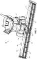
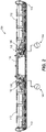
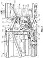
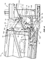
- Schneidwerk (104) für einen Mähdrescher (100), wobei das Schneidwerk (104) Folgendes umfasst:einen Mittelabschnitt (116), der zur Befestigung an einem Mähdrescher (100) ausgelegt und mit einem Riemen (132) bereitgestellt ist, der in einer Rückwärtsrichtung betreibbar ist, um dem Mähdrescher (100) Erntegut zuzuführen;einen ersten und einen zweiten Flügel (112), die sich in entgegengesetzten seitlichen Richtungen vom Mittelabschnitt (116) erstrecken, wobei sowohl der erste als auch der zweite Flügel (112) einen Schneidwerkriemen (128) umfassen, der betreibbar ist, um dem Mittelabschnitt (116) Erntegut zuzuführen, wobei der erste und der zweite Flügel (112) relativ zum Mittelabschnitt (116) einzeln drehbar gelagert sind; undeinen Mähbalken (124), der an einer Vorderkante des Schneidwerks (104) quer über den Mittelabschnitt (116) und den ersten und den zweiten Flügel (112) positioniert ist, wobei der Mähbalken (124) betreibbar ist, um sich hin- und herzubewegen, um Erntegut vom Boden zu schneiden, wobei der erste und der zweite Flügel (112) durch jeweilige Verbindungsgestänge (136) mit dem Mittelabschnitt (116) gekoppelt und ferner relativ zum Mittelabschnitt (116) durch ein jeweiliges elastisches Schwebeelement (140) gestützt werden, wobei jedes elastische Schwebeelement (140) betreibbar ist, um eine Kraftausgabe zu erzeugen, die mit einer Position des Flügels in Bezug auf den Mittelabschnitt (116) variiert, dadurch gekennzeichnet, dass jedes elastische Schwebeelement (140) zwischen dem Mittelabschnitt (116) und dem jeweiligen ersten bzw. zweiten Flügel (112) durch ein jeweiliges Schwebegestänge (142) gekoppelt ist, das über einen Bereich von Positionen betreibbar ist, um einen mechanischen Vorteil zwischen dem elastischen Schwebeelement (140) und dem jeweiligen Flügel (112) zu variieren, unddass die Bewegung des Schwebegestänges (142) den mechanischen vorteil verringert, wenn die Kraftausgabe im entsprechenden elastischen Schwebeelement (140) zunimmt, und die Bewegung des Schwebegestänges (142) den mechanischen Vorteil vergrößert, wenn die Kraftausgabe im entsprechenden elastischen Schwebeelement (140) abnimmt, so dass eine Änderung einer Gesamtflügelschwebekraft, die durch das elastische Schwebeelement (140) auf den Flügel (112) ausgeübt wird, gedämpft wird.
- Schneidwerk (104) nach Anspruch 1, wobei jedes der elastischen Schwebeelemente (140) einen einfachwirkenden Hydraulikzylinder beinhaltet, der mit einem gasgefüllten Speicher (144) gekoppelt ist.
- Schneidwerk (104) nach Anspruch 1, wobei jedes jeweilige Verbindungsgestänge (136) als ein viergliedriges Gestänge bereitgestellt ist, das aus einem Rahmenabschnitt (150) des Flügels (112), einem Rahmenabschnitt (154) des Mittelabschnitts (116) und zwei Verbindungsgliedern (158A, 158B) dazwischen besteht.
- Schneidwerk (104) nach Anspruch 3, wobei die beiden Verbindungsglieder (158A, 158B) an zwei Drehpunkten (160A, 164B) am Rahmenabschnitt (154) des Mittelabschnitts (116) gekoppelt sind.
- Schneidwerk (104) nach Anspruch 4, wobei eine Primärverbindung (176) jedes jeweiligen Schwebegestänges (142) ein erstes Ende aufweist, das drehbar sowohl mit einem ersten Ende des elastischen Schwebeelements (140) als auch einer Sekundärverbindung (180) des Schwebegestänges (142) gekoppelt ist, und wobei ein zweites Ende der Primärverbindung (176) drehbar mit einem dritten Drehpunkt (160B) am Rahmenabschnitt (154) des Mittelabschnitts (116) gekoppelt ist.
- Schneidwerk (104) nach Anspruch 5, wobei ein zweites Ende des elastischen Schwebeelements (140) ein Drehgelenk mit dem Rahmenabschnitt (150) des Flügels (112) definiert und das Drehgelenk in einen Schlitz (188) eingezwängt ist, der in der Primärverbindung (176) zwischen dem ersten und dem zweiten Ende bereitgestellt ist.
- Schneidwerk (104) nach Anspruch 6, wobei die Bewegung des Schwebegestänges (142) den mechanischen Vorteil erhöht, indem sie das Drehgelenk (160A, 160B) näher an eine Ausrichtung zwischen dem ersten und dem zweiten Ende der Primärverbindung des Schwebegestänges (142) bringt.
- Schneidwerk (104) nach Anspruch 5, wobei die Sekundärverbindung (180) des Schwebegestänges (142) an einer Position zwischen zwei Drehpunkten (160A, 160B), an denen die beiden Verbindungsglieder (158A, 158B) mit dem Rahmenabschnitt (150) des Flügels (112) gekoppelt sind, drehbar mit dem Rahmenabschnitt (150) des Flügels (112) gekoppelt ist.
- Schneidwerk (104) nach Anspruch 1, wobei die jeweiligen Schwebegestänge (142) und die jeweiligen elastischen Schwebeelemente (140) passiv sind, wobei ihr Betrieb durch die Position des jeweiligen ersten bzw. zweiten Flügels (112) in Bezug auf den Mittelabschnitt (116) vorgegeben wird.
Applications Claiming Priority (1)
| Application Number | Priority Date | Filing Date | Title |
|---|---|---|---|
| US15/785,092 US10433486B2 (en) | 2017-10-16 | 2017-10-16 | System and method for wing float on a combine draper header |
Publications (2)
| Publication Number | Publication Date |
|---|---|
| EP3469876A1 EP3469876A1 (de) | 2019-04-17 |
| EP3469876B1 true EP3469876B1 (de) | 2020-07-15 |
Family
ID=63857825
Family Applications (1)
| Application Number | Title | Priority Date | Filing Date |
|---|---|---|---|
| EP18200409.3A Active EP3469876B1 (de) | 2017-10-16 | 2018-10-15 | System zur schwebenden aufhängung eines seitenflügels an einem schneidwerk eines mähdreschers |
Country Status (3)
| Country | Link |
|---|---|
| US (1) | US10433486B2 (de) |
| EP (1) | EP3469876B1 (de) |
| BR (1) | BR102018071042B1 (de) |
Families Citing this family (16)
| Publication number | Priority date | Publication date | Assignee | Title |
|---|---|---|---|---|
| US10617059B2 (en) * | 2016-06-21 | 2020-04-14 | Macdon Industries Ltd. | Crop machine with an electronically controlled hydraulic cylinder flotation system |
| US10433483B2 (en) * | 2017-08-21 | 2019-10-08 | Cnh Industrial America Llc | Agricultural header with one or more movable wing sections |
| WO2019136281A1 (en) * | 2018-01-04 | 2019-07-11 | Cnh Industrial America Llc | Agricultural harvester with header having conformable portions |
| US10813289B2 (en) * | 2018-06-05 | 2020-10-27 | Deere & Company | Single top beam folding corn head mainframe |
| US10952375B2 (en) * | 2018-06-29 | 2021-03-23 | Macdon Industries Ltd | Crop header with wing balance calibration |
| US11297765B2 (en) * | 2018-07-02 | 2022-04-12 | Deere & Company | Suspension compliance to reduce frame loading |
| WO2020101871A1 (en) * | 2018-11-16 | 2020-05-22 | Cnh Industrial America Llc | Header with modular rigid frame |
| US11191212B2 (en) * | 2019-04-23 | 2021-12-07 | Deere & Company | Controlled float on an agricultural harvester for header leveling |
| US11219162B2 (en) * | 2019-04-23 | 2022-01-11 | Deere & Company | Controlled header lowering on an agricultural harvester |
| US11224164B2 (en) * | 2019-04-23 | 2022-01-18 | Deere & Company | Damped float response on an agricultural harvester |
| US11064654B2 (en) * | 2019-05-01 | 2021-07-20 | Deere & Company | Float adjustment |
| CA190292S (en) * | 2019-05-09 | 2021-02-26 | Deere & Co | Fender for an agricultural machine |
| US11019770B2 (en) * | 2019-05-28 | 2021-06-01 | Deere & Company | Harvester wing leveling configuration |
| US11627701B2 (en) * | 2019-10-31 | 2023-04-18 | Deere & Company | Agricultural header with flexible joint |
| US11375658B2 (en) * | 2019-12-23 | 2022-07-05 | Cnh Industrial America Llc | System and method for leveling a cutter bar of a harvester |
| US11234368B2 (en) * | 2019-12-23 | 2022-02-01 | Cnh Industrial America Llc | Cutter bar assembly for a harvester |
Citations (3)
| Publication number | Priority date | Publication date | Assignee | Title |
|---|---|---|---|---|
| US6675568B2 (en) | 2001-06-18 | 2004-01-13 | Macdon Industries Ltd. | Multi-section header with flexible crop cutting knife |
| US20080295473A1 (en) | 2007-06-04 | 2008-12-04 | Claas Selbstfahrende Erntemaschinen Gmbh | Winged header apparatus and method for a combine |
| EP3153004B1 (de) | 2015-10-05 | 2018-03-28 | Carl Geringhoff GmbH & Co. KG | Schneidwerk mit verstellbarer seitenrahmenentlastung |
Family Cites Families (56)
| Publication number | Priority date | Publication date | Assignee | Title |
|---|---|---|---|---|
| US2608041A (en) | 1947-01-24 | 1952-08-26 | Case Co J I | Conveying means for harvester headers |
| NL6414183A (de) | 1964-12-05 | 1966-06-06 | ||
| NL6903371A (de) | 1969-03-05 | 1970-09-08 | ||
| US4487004A (en) * | 1983-06-03 | 1984-12-11 | Kejr Melvin P | Combine harvester apparatus |
| CA2110775C (en) | 1993-12-06 | 1999-03-02 | Gregory J. Honey | A feeder adapter for mounting a combine header to a feeder housing of a combine |
| DE19523255A1 (de) | 1995-06-27 | 1997-01-02 | Claas Saulgau Gmbh | Erntevorsatz an landwirtschaftlichen Arbeitsmaschinen zum Aufnehmen und Weiterführen von Halmfrüchten, beispielsweise Maispflanzen |
| US5577563A (en) | 1995-07-27 | 1996-11-26 | Holen; Kurt | Stack-folding toolbar with floating wings |
| US5724798A (en) | 1996-07-08 | 1998-03-10 | Byron Enterprises Inc. | Latch for a folding corn head |
| US5673543A (en) | 1996-01-04 | 1997-10-07 | Byron Enterprises, Inc | Foldable corn head with unobstructed auger |
| US6003615A (en) | 1998-08-19 | 1999-12-21 | Moore; Paul O. | Stacking tool bar including a wing flex structure |
| US6202397B1 (en) | 1999-05-27 | 2001-03-20 | Deere & Company | Draper belt tensioning mechanism for a harvesting platform |
| DE10039097A1 (de) | 2000-08-07 | 2002-02-21 | Claas Saulgau Gmbh | Verfahren und Vorrichtung zum Schwenken der Abteiler von mehrteiligen landwirtschaftlichen Erntemaschinen |
| HUP0300512A2 (hu) | 2002-03-28 | 2004-09-28 | Claas Saulgau Gmbh | Kaszáló berendezés |
| DE10221983A1 (de) | 2002-05-17 | 2003-11-27 | Kemper Gmbh Maschf | Erntevorsatz |
| DE10250337A1 (de) | 2002-10-29 | 2004-05-19 | Maschinenfabrik Kemper Gmbh & Co. Kg | Verstelleinrichtung für einen Erntevorsatz |
| US6865871B2 (en) | 2003-07-14 | 2005-03-15 | Macdon Industries Ltd. | Crop feed arrangement for the header of a combine harvester |
| US7168226B2 (en) | 2004-03-31 | 2007-01-30 | Cnh America Llc | Independent hydraulic header lift and flotation system |
| US7392646B2 (en) | 2004-06-16 | 2008-07-01 | Macdon Industries Ltd. | Reversible feed roller with radially extendible fingers |
| US7467668B2 (en) | 2005-03-31 | 2008-12-23 | Kimball Von D | Transport lock joint for stack fold toolbar |
| US20080276590A1 (en) | 2006-02-10 | 2008-11-13 | Agco Corporation | Flexible draper and cutter bar with tilt arm for cutterbar drive |
| US20070193243A1 (en) | 2006-02-10 | 2007-08-23 | Schmidt James R | Combine Harvester Draper Header Having Flexible Cutterbar |
| US7540130B2 (en) | 2006-03-02 | 2009-06-02 | Deere & Company | Height control for a multi-section cutting platform in an agricultural harvesting machine |
| US7918076B2 (en) | 2006-09-25 | 2011-04-05 | Macdon Industries Ltd. | Device for maintaining wing balance on a multi-section header |
| CA2572274C (en) | 2006-12-29 | 2014-05-27 | Honey Bee Manufacturing Ltd. | Rock trap for combine header |
| US7587885B2 (en) | 2007-06-04 | 2009-09-15 | Claas Selbstfahrende Emtemaschinen Gmbh | Central auger crop feed system for a harvester |
| US7921627B2 (en) | 2008-05-09 | 2011-04-12 | Agco Corporation | Interlocking belt guards for a draper header |
| US7788891B2 (en) | 2008-06-27 | 2010-09-07 | Deere & Company | Endless belt mounting configuration for an agricultural harvester |
| US8281561B2 (en) | 2010-08-17 | 2012-10-09 | Deere & Company | Flexible draper belt drive for an agricultural harvesting machine |
| DE102010037131A1 (de) | 2010-08-24 | 2012-03-01 | Claas Selbstfahrende Erntemaschinen Gmbh | Schneidwerk |
| US8087224B1 (en) | 2010-09-16 | 2012-01-03 | Deere & Company | Flexible draper platform with pivot geometry |
| US7992372B1 (en) * | 2010-09-16 | 2011-08-09 | Deere & Company | Draper platform with breakaway joint |
| US8336280B2 (en) | 2011-05-20 | 2012-12-25 | Deere & Company | Pivoting center conveyor for draper platform |
| US8544250B2 (en) | 2011-10-25 | 2013-10-01 | Deere & Company | Draper platform with center conveyor and method of replacing the center conveyor belt |
| ITPD20120242A1 (it) | 2012-08-06 | 2014-02-07 | Cressoni S P A Flli | Testata ripiegabile per macchina spannocchiatrice e/o mietitrebbia e metodo di ripiegatura di una testata di macchina spannocchiatrice e/o mietitrebbia |
| US8695315B2 (en) | 2012-08-09 | 2014-04-15 | Deere & Company | Draper header with pivoting side draper conveyors |
| US9072222B2 (en) | 2012-09-20 | 2015-07-07 | Deere & Company | Self-centering cover for hinged row crop harvesting head |
| US9198353B2 (en) * | 2012-09-20 | 2015-12-01 | Deere & Company | Hinged row crop harvesting head |
| DE102013100322A1 (de) | 2013-01-14 | 2014-07-17 | Claas Selbstfahrende Erntemaschinen Gmbh | Schneidwerk |
| US9198349B2 (en) | 2013-07-12 | 2015-12-01 | Deere & Company | Articulated harvesting head ground force control circuit |
| US9144199B2 (en) | 2013-08-30 | 2015-09-29 | Deere & Company | Articulated harvesting head load sensor arrangement |
| DE102014009161B4 (de) | 2014-06-25 | 2023-01-26 | Carl Geringhoff Gmbh & Co. Kg | Schneidwerk mit Mittelteil und dazu verstellbaren Seitenteilen |
| DE102014216112A1 (de) | 2014-08-13 | 2016-02-18 | Walter Schmid | Selbstfahrende Erntemaschine |
| US9788486B2 (en) | 2014-12-30 | 2017-10-17 | Agco Corporation | Grain header with swathing and chopping capability |
| BR102016005189B1 (pt) | 2015-03-13 | 2020-11-17 | Cnh Industrial Belgium Nv | Colheitadeira agricola |
| US9668412B2 (en) | 2015-05-01 | 2017-06-06 | Deere & Company | Harvesting head height control circuit |
| US20160360699A1 (en) | 2015-06-10 | 2016-12-15 | Jose Luis Allochis | Conveyor belt tensing apparatus for a harvesting header |
| DE102015118143A1 (de) | 2015-10-23 | 2017-04-27 | Arnold Jäger Holding GmbH | Nockenriemen, insbesondere für landwirtschaftliche Maschinen |
| BE1023925B1 (nl) | 2016-03-01 | 2017-09-13 | Cnh Industrial Belgium Nv | Toevoertoestel voor maaidorser |
| BE1024333B1 (nl) | 2016-06-23 | 2018-02-01 | Cnh Industrial Belgium Nv | Maaibordsteun voor een oogstmachine |
| US10070575B2 (en) | 2016-08-05 | 2018-09-11 | Cnh Industrial America Llc | Agricultural machine with folding header |
| US20180070526A1 (en) | 2016-09-13 | 2018-03-15 | Cnh Industrial Canada, Ltd. | Apparatus and method to minimize transport dimensions of agricultural implements |
| DE102016118174A1 (de) | 2016-09-26 | 2018-03-29 | Claas Selbstfahrende Erntemaschinen Gmbh | Schneidwerk |
| US10375881B2 (en) | 2017-05-23 | 2019-08-13 | Cnh Industrial America Llc | Agricultural machine with sectional header |
| US10299437B2 (en) | 2017-07-17 | 2019-05-28 | Cnh Industrial America Llc | Header for an agricultural vehicle with deformable supports |
| US10820509B2 (en) | 2017-08-08 | 2020-11-03 | Cnh Industrial America Llc | Foldable corn head |
| US10433483B2 (en) * | 2017-08-21 | 2019-10-08 | Cnh Industrial America Llc | Agricultural header with one or more movable wing sections |
-
2017
- 2017-10-16 US US15/785,092 patent/US10433486B2/en active Active
-
2018
- 2018-10-11 BR BR102018071042-7A patent/BR102018071042B1/pt active IP Right Grant
- 2018-10-15 EP EP18200409.3A patent/EP3469876B1/de active Active
Patent Citations (3)
| Publication number | Priority date | Publication date | Assignee | Title |
|---|---|---|---|---|
| US6675568B2 (en) | 2001-06-18 | 2004-01-13 | Macdon Industries Ltd. | Multi-section header with flexible crop cutting knife |
| US20080295473A1 (en) | 2007-06-04 | 2008-12-04 | Claas Selbstfahrende Erntemaschinen Gmbh | Winged header apparatus and method for a combine |
| EP3153004B1 (de) | 2015-10-05 | 2018-03-28 | Carl Geringhoff GmbH & Co. KG | Schneidwerk mit verstellbarer seitenrahmenentlastung |
Also Published As
| Publication number | Publication date |
|---|---|
| US20190110402A1 (en) | 2019-04-18 |
| US10433486B2 (en) | 2019-10-08 |
| BR102018071042B1 (pt) | 2023-11-14 |
| EP3469876A1 (de) | 2019-04-17 |
| BR102018071042A2 (pt) | 2019-06-04 |
Similar Documents
| Publication | Publication Date | Title |
|---|---|---|
| EP3469876B1 (de) | System zur schwebenden aufhängung eines seitenflügels an einem schneidwerk eines mähdreschers | |
| EP3473076B1 (de) | Selbstständiger mähdrescherschneidwerkflügelnivellierer | |
| EP3469878B1 (de) | Rollzentrum für erntevorsatzrahmensteuerungsarmen | |
| US11778946B2 (en) | Flexible header with sectional height adjustment | |
| EP3446558B2 (de) | Landwirtschaftlicher erntevorsatz mit einem oder mehreren beweglichen flügelabschnitten | |
| US7726111B2 (en) | Suspension system for a belt pickup header in an agricultural harvester | |
| EP1401256B1 (de) | Mehrteiliges schneidwerk mit flexiblem gewächsschneidemesser | |
| EP2374344B1 (de) | Landwirtschaftlicher Erntevorsatz mit automatischer Druckanpassung des längsverstellbaren flexiblen Schneidwerks | |
| US8051633B2 (en) | Cutterbar adjustment support for a crop harvesting header | |
| AU2002257470A1 (en) | Multi-section header with flexible crop cutting knife | |
| EP3466241B1 (de) | Landwirtschaftlicher erntekopf mit schwimmerarmschwenkpunkt unterhalb der hubmesser | |
| US11553645B2 (en) | Flex arm air bag linkage | |
| EP3610716B1 (de) | System und verfahren zur bodenverfolgung eines mähdreschers mit flexiblem mähbalken | |
| CA3079836A1 (en) | Float adjustment | |
| EP3811763B1 (de) | Stützgestänge eines mähbalkens | |
| EP3815505B1 (de) | Torsionsausgeglichener erntevorsatz | |
| US20230240179A1 (en) | Agricultural header float arm system |
Legal Events
| Date | Code | Title | Description |
|---|---|---|---|
| PUAI | Public reference made under article 153(3) epc to a published international application that has entered the european phase |
Free format text: ORIGINAL CODE: 0009012 |
|
| STAA | Information on the status of an ep patent application or granted ep patent |
Free format text: STATUS: THE APPLICATION HAS BEEN PUBLISHED |
|
| AK | Designated contracting states |
Kind code of ref document: A1 Designated state(s): AL AT BE BG CH CY CZ DE DK EE ES FI FR GB GR HR HU IE IS IT LI LT LU LV MC MK MT NL NO PL PT RO RS SE SI SK SM TR |
|
| AX | Request for extension of the european patent |
Extension state: BA ME |
|
| TPAC | Observations filed by third parties |
Free format text: ORIGINAL CODE: EPIDOSNTIPA |
|
| STAA | Information on the status of an ep patent application or granted ep patent |
Free format text: STATUS: REQUEST FOR EXAMINATION WAS MADE |
|
| 17P | Request for examination filed |
Effective date: 20191017 |
|
| RBV | Designated contracting states (corrected) |
Designated state(s): AL AT BE BG CH CY CZ DE DK EE ES FI FR GB GR HR HU IE IS IT LI LT LU LV MC MK MT NL NO PL PT RO RS SE SI SK SM TR |
|
| GRAP | Despatch of communication of intention to grant a patent |
Free format text: ORIGINAL CODE: EPIDOSNIGR1 |
|
| STAA | Information on the status of an ep patent application or granted ep patent |
Free format text: STATUS: GRANT OF PATENT IS INTENDED |
|
| INTG | Intention to grant announced |
Effective date: 20200214 |
|
| GRAS | Grant fee paid |
Free format text: ORIGINAL CODE: EPIDOSNIGR3 |
|
| GRAA | (expected) grant |
Free format text: ORIGINAL CODE: 0009210 |
|
| STAA | Information on the status of an ep patent application or granted ep patent |
Free format text: STATUS: THE PATENT HAS BEEN GRANTED |
|
| AK | Designated contracting states |
Kind code of ref document: B1 Designated state(s): AL AT BE BG CH CY CZ DE DK EE ES FI FR GB GR HR HU IE IS IT LI LT LU LV MC MK MT NL NO PL PT RO RS SE SI SK SM TR |
|
| REG | Reference to a national code |
Ref country code: CH Ref legal event code: EP Ref country code: GB Ref legal event code: FG4D |
|
| REG | Reference to a national code |
Ref country code: IE Ref legal event code: FG4D |
|
| REG | Reference to a national code |
Ref country code: DE Ref legal event code: R096 Ref document number: 602018006042 Country of ref document: DE |
|
| REG | Reference to a national code |
Ref country code: AT Ref legal event code: REF Ref document number: 1289928 Country of ref document: AT Kind code of ref document: T Effective date: 20200815 |
|
| REG | Reference to a national code |
Ref country code: LT Ref legal event code: MG4D |
|
| REG | Reference to a national code |
Ref country code: AT Ref legal event code: MK05 Ref document number: 1289928 Country of ref document: AT Kind code of ref document: T Effective date: 20200715 |
|
| REG | Reference to a national code |
Ref country code: NL Ref legal event code: MP Effective date: 20200715 |
|
| PG25 | Lapsed in a contracting state [announced via postgrant information from national office to epo] |
Ref country code: LT Free format text: LAPSE BECAUSE OF FAILURE TO SUBMIT A TRANSLATION OF THE DESCRIPTION OR TO PAY THE FEE WITHIN THE PRESCRIBED TIME-LIMIT Effective date: 20200715 Ref country code: ES Free format text: LAPSE BECAUSE OF FAILURE TO SUBMIT A TRANSLATION OF THE DESCRIPTION OR TO PAY THE FEE WITHIN THE PRESCRIBED TIME-LIMIT Effective date: 20200715 Ref country code: PT Free format text: LAPSE BECAUSE OF FAILURE TO SUBMIT A TRANSLATION OF THE DESCRIPTION OR TO PAY THE FEE WITHIN THE PRESCRIBED TIME-LIMIT Effective date: 20201116 Ref country code: BG Free format text: LAPSE BECAUSE OF FAILURE TO SUBMIT A TRANSLATION OF THE DESCRIPTION OR TO PAY THE FEE WITHIN THE PRESCRIBED TIME-LIMIT Effective date: 20201015 Ref country code: SE Free format text: LAPSE BECAUSE OF FAILURE TO SUBMIT A TRANSLATION OF THE DESCRIPTION OR TO PAY THE FEE WITHIN THE PRESCRIBED TIME-LIMIT Effective date: 20200715 Ref country code: AT Free format text: LAPSE BECAUSE OF FAILURE TO SUBMIT A TRANSLATION OF THE DESCRIPTION OR TO PAY THE FEE WITHIN THE PRESCRIBED TIME-LIMIT Effective date: 20200715 Ref country code: HR Free format text: LAPSE BECAUSE OF FAILURE TO SUBMIT A TRANSLATION OF THE DESCRIPTION OR TO PAY THE FEE WITHIN THE PRESCRIBED TIME-LIMIT Effective date: 20200715 Ref country code: GR Free format text: LAPSE BECAUSE OF FAILURE TO SUBMIT A TRANSLATION OF THE DESCRIPTION OR TO PAY THE FEE WITHIN THE PRESCRIBED TIME-LIMIT Effective date: 20201016 Ref country code: NO Free format text: LAPSE BECAUSE OF FAILURE TO SUBMIT A TRANSLATION OF THE DESCRIPTION OR TO PAY THE FEE WITHIN THE PRESCRIBED TIME-LIMIT Effective date: 20201015 Ref country code: FI Free format text: LAPSE BECAUSE OF FAILURE TO SUBMIT A TRANSLATION OF THE DESCRIPTION OR TO PAY THE FEE WITHIN THE PRESCRIBED TIME-LIMIT Effective date: 20200715 |
|
| PG25 | Lapsed in a contracting state [announced via postgrant information from national office to epo] |
Ref country code: RS Free format text: LAPSE BECAUSE OF FAILURE TO SUBMIT A TRANSLATION OF THE DESCRIPTION OR TO PAY THE FEE WITHIN THE PRESCRIBED TIME-LIMIT Effective date: 20200715 Ref country code: LV Free format text: LAPSE BECAUSE OF FAILURE TO SUBMIT A TRANSLATION OF THE DESCRIPTION OR TO PAY THE FEE WITHIN THE PRESCRIBED TIME-LIMIT Effective date: 20200715 Ref country code: PL Free format text: LAPSE BECAUSE OF FAILURE TO SUBMIT A TRANSLATION OF THE DESCRIPTION OR TO PAY THE FEE WITHIN THE PRESCRIBED TIME-LIMIT Effective date: 20200715 Ref country code: IS Free format text: LAPSE BECAUSE OF FAILURE TO SUBMIT A TRANSLATION OF THE DESCRIPTION OR TO PAY THE FEE WITHIN THE PRESCRIBED TIME-LIMIT Effective date: 20201115 |
|
| PG25 | Lapsed in a contracting state [announced via postgrant information from national office to epo] |
Ref country code: NL Free format text: LAPSE BECAUSE OF FAILURE TO SUBMIT A TRANSLATION OF THE DESCRIPTION OR TO PAY THE FEE WITHIN THE PRESCRIBED TIME-LIMIT Effective date: 20200715 |
|
| REG | Reference to a national code |
Ref country code: DE Ref legal event code: R026 Ref document number: 602018006042 Country of ref document: DE |
|
| PLBI | Opposition filed |
Free format text: ORIGINAL CODE: 0009260 |
|
| PG25 | Lapsed in a contracting state [announced via postgrant information from national office to epo] |
Ref country code: CZ Free format text: LAPSE BECAUSE OF FAILURE TO SUBMIT A TRANSLATION OF THE DESCRIPTION OR TO PAY THE FEE WITHIN THE PRESCRIBED TIME-LIMIT Effective date: 20200715 Ref country code: DK Free format text: LAPSE BECAUSE OF FAILURE TO SUBMIT A TRANSLATION OF THE DESCRIPTION OR TO PAY THE FEE WITHIN THE PRESCRIBED TIME-LIMIT Effective date: 20200715 Ref country code: RO Free format text: LAPSE BECAUSE OF FAILURE TO SUBMIT A TRANSLATION OF THE DESCRIPTION OR TO PAY THE FEE WITHIN THE PRESCRIBED TIME-LIMIT Effective date: 20200715 Ref country code: EE Free format text: LAPSE BECAUSE OF FAILURE TO SUBMIT A TRANSLATION OF THE DESCRIPTION OR TO PAY THE FEE WITHIN THE PRESCRIBED TIME-LIMIT Effective date: 20200715 Ref country code: SM Free format text: LAPSE BECAUSE OF FAILURE TO SUBMIT A TRANSLATION OF THE DESCRIPTION OR TO PAY THE FEE WITHIN THE PRESCRIBED TIME-LIMIT Effective date: 20200715 Ref country code: IT Free format text: LAPSE BECAUSE OF FAILURE TO SUBMIT A TRANSLATION OF THE DESCRIPTION OR TO PAY THE FEE WITHIN THE PRESCRIBED TIME-LIMIT Effective date: 20200715 |
|
| PLAX | Notice of opposition and request to file observation + time limit sent |
Free format text: ORIGINAL CODE: EPIDOSNOBS2 |
|
| 26 | Opposition filed |
Opponent name: CARL GERINGHOFF GMBH & CO. KG Effective date: 20210413 |
|
| PG25 | Lapsed in a contracting state [announced via postgrant information from national office to epo] |
Ref country code: AL Free format text: LAPSE BECAUSE OF FAILURE TO SUBMIT A TRANSLATION OF THE DESCRIPTION OR TO PAY THE FEE WITHIN THE PRESCRIBED TIME-LIMIT Effective date: 20200715 |
|
| PG25 | Lapsed in a contracting state [announced via postgrant information from national office to epo] |
Ref country code: MC Free format text: LAPSE BECAUSE OF FAILURE TO SUBMIT A TRANSLATION OF THE DESCRIPTION OR TO PAY THE FEE WITHIN THE PRESCRIBED TIME-LIMIT Effective date: 20200715 Ref country code: SK Free format text: LAPSE BECAUSE OF FAILURE TO SUBMIT A TRANSLATION OF THE DESCRIPTION OR TO PAY THE FEE WITHIN THE PRESCRIBED TIME-LIMIT Effective date: 20200715 Ref country code: LU Free format text: LAPSE BECAUSE OF NON-PAYMENT OF DUE FEES Effective date: 20201015 |
|
| REG | Reference to a national code |
Ref country code: BE Ref legal event code: MM Effective date: 20201031 |
|
| PG25 | Lapsed in a contracting state [announced via postgrant information from national office to epo] |
Ref country code: FR Free format text: LAPSE BECAUSE OF NON-PAYMENT OF DUE FEES Effective date: 20201031 |
|
| PG25 | Lapsed in a contracting state [announced via postgrant information from national office to epo] |
Ref country code: SI Free format text: LAPSE BECAUSE OF FAILURE TO SUBMIT A TRANSLATION OF THE DESCRIPTION OR TO PAY THE FEE WITHIN THE PRESCRIBED TIME-LIMIT Effective date: 20200715 Ref country code: BE Free format text: LAPSE BECAUSE OF NON-PAYMENT OF DUE FEES Effective date: 20201031 |
|
| PLBB | Reply of patent proprietor to notice(s) of opposition received |
Free format text: ORIGINAL CODE: EPIDOSNOBS3 |
|
| PG25 | Lapsed in a contracting state [announced via postgrant information from national office to epo] |
Ref country code: IE Free format text: LAPSE BECAUSE OF NON-PAYMENT OF DUE FEES Effective date: 20201015 |
|
| PLBP | Opposition withdrawn |
Free format text: ORIGINAL CODE: 0009264 |
|
| PLBD | Termination of opposition procedure: decision despatched |
Free format text: ORIGINAL CODE: EPIDOSNOPC1 |
|
| REG | Reference to a national code |
Ref country code: DE Ref legal event code: R100 Ref document number: 602018006042 Country of ref document: DE |
|
| REG | Reference to a national code |
Ref country code: CH Ref legal event code: PL |
|
| PG25 | Lapsed in a contracting state [announced via postgrant information from national office to epo] |
Ref country code: TR Free format text: LAPSE BECAUSE OF FAILURE TO SUBMIT A TRANSLATION OF THE DESCRIPTION OR TO PAY THE FEE WITHIN THE PRESCRIBED TIME-LIMIT Effective date: 20200715 Ref country code: MT Free format text: LAPSE BECAUSE OF FAILURE TO SUBMIT A TRANSLATION OF THE DESCRIPTION OR TO PAY THE FEE WITHIN THE PRESCRIBED TIME-LIMIT Effective date: 20200715 Ref country code: CY Free format text: LAPSE BECAUSE OF FAILURE TO SUBMIT A TRANSLATION OF THE DESCRIPTION OR TO PAY THE FEE WITHIN THE PRESCRIBED TIME-LIMIT Effective date: 20200715 |
|
| PG25 | Lapsed in a contracting state [announced via postgrant information from national office to epo] |
Ref country code: MK Free format text: LAPSE BECAUSE OF FAILURE TO SUBMIT A TRANSLATION OF THE DESCRIPTION OR TO PAY THE FEE WITHIN THE PRESCRIBED TIME-LIMIT Effective date: 20200715 |
|
| PLBM | Termination of opposition procedure: date of legal effect published |
Free format text: ORIGINAL CODE: 0009276 |
|
| PG25 | Lapsed in a contracting state [announced via postgrant information from national office to epo] |
Ref country code: LI Free format text: LAPSE BECAUSE OF NON-PAYMENT OF DUE FEES Effective date: 20211031 Ref country code: CH Free format text: LAPSE BECAUSE OF NON-PAYMENT OF DUE FEES Effective date: 20211031 |
|
| 27C | Opposition proceedings terminated |
Effective date: 20220514 |
|
| GBPC | Gb: european patent ceased through non-payment of renewal fee |
Effective date: 20221015 |
|
| PG25 | Lapsed in a contracting state [announced via postgrant information from national office to epo] |
Ref country code: GB Free format text: LAPSE BECAUSE OF NON-PAYMENT OF DUE FEES Effective date: 20221015 |
|
| PGFP | Annual fee paid to national office [announced via postgrant information from national office to epo] |
Ref country code: DE Payment date: 20230920 Year of fee payment: 6 |