EP3469876A1 - System und verfahren zum gleiten einer horde an einem draper-schneidwerk eines mähdreschers - Google Patents
System und verfahren zum gleiten einer horde an einem draper-schneidwerk eines mähdreschers Download PDFInfo
- Publication number
- EP3469876A1 EP3469876A1 EP18200409.3A EP18200409A EP3469876A1 EP 3469876 A1 EP3469876 A1 EP 3469876A1 EP 18200409 A EP18200409 A EP 18200409A EP 3469876 A1 EP3469876 A1 EP 3469876A1
- Authority
- EP
- European Patent Office
- Prior art keywords
- float
- wing
- center section
- linkage
- resilient
- Prior art date
- Legal status (The legal status is an assumption and is not a legal conclusion. Google has not performed a legal analysis and makes no representation as to the accuracy of the status listed.)
- Granted
Links
Images

Classifications
-
- A—HUMAN NECESSITIES
- A01—AGRICULTURE; FORESTRY; ANIMAL HUSBANDRY; HUNTING; TRAPPING; FISHING
- A01D—HARVESTING; MOWING
- A01D61/00—Elevators or conveyors for binders or combines
- A01D61/002—Elevators or conveyors for binders or combines transversal conveying devices
-
- A—HUMAN NECESSITIES
- A01—AGRICULTURE; FORESTRY; ANIMAL HUSBANDRY; HUNTING; TRAPPING; FISHING
- A01D—HARVESTING; MOWING
- A01D41/00—Combines, i.e. harvesters or mowers combined with threshing devices
- A01D41/12—Details of combines
- A01D41/14—Mowing tables
-
- A—HUMAN NECESSITIES
- A01—AGRICULTURE; FORESTRY; ANIMAL HUSBANDRY; HUNTING; TRAPPING; FISHING
- A01D—HARVESTING; MOWING
- A01D41/00—Combines, i.e. harvesters or mowers combined with threshing devices
- A01D41/12—Details of combines
- A01D41/14—Mowing tables
- A01D41/144—Foldable headers
-
- A—HUMAN NECESSITIES
- A01—AGRICULTURE; FORESTRY; ANIMAL HUSBANDRY; HUNTING; TRAPPING; FISHING
- A01D—HARVESTING; MOWING
- A01D57/00—Delivering mechanisms for harvesters or mowers
- A01D57/20—Delivering mechanisms for harvesters or mowers with conveyor belts
-
- A—HUMAN NECESSITIES
- A01—AGRICULTURE; FORESTRY; ANIMAL HUSBANDRY; HUNTING; TRAPPING; FISHING
- A01D—HARVESTING; MOWING
- A01D61/00—Elevators or conveyors for binders or combines
- A01D61/008—Elevators or conveyors for binders or combines for longitudinal conveying, especially for combines
-
- A—HUMAN NECESSITIES
- A01—AGRICULTURE; FORESTRY; ANIMAL HUSBANDRY; HUNTING; TRAPPING; FISHING
- A01D—HARVESTING; MOWING
- A01D61/00—Elevators or conveyors for binders or combines
- A01D61/02—Endless belts
-
- A—HUMAN NECESSITIES
- A01—AGRICULTURE; FORESTRY; ANIMAL HUSBANDRY; HUNTING; TRAPPING; FISHING
- A01D—HARVESTING; MOWING
- A01D34/00—Mowers; Mowing apparatus of harvesters
- A01D34/01—Mowers; Mowing apparatus of harvesters characterised by features relating to the type of cutting apparatus
- A01D34/02—Mowers; Mowing apparatus of harvesters characterised by features relating to the type of cutting apparatus having reciprocating cutters
- A01D34/03—Mowers; Mowing apparatus of harvesters characterised by features relating to the type of cutting apparatus having reciprocating cutters mounted on a vehicle, e.g. a tractor, or drawn by an animal or a vehicle
- A01D34/04—Mowers; Mowing apparatus of harvesters characterised by features relating to the type of cutting apparatus having reciprocating cutters mounted on a vehicle, e.g. a tractor, or drawn by an animal or a vehicle with cutters at the front
Definitions
- the disclosure relates to headers for combine harvesters, and more particularly draper headers having separate lateral wings for ground following and draper belts for feeding cut crops into a feeder house.
- the disclosure provides, in one aspect, a draper header for a combine.
- a center section is adapted for attachment to the combine and is provided with a belt operable in a rearward direction for feeding crop material into the combine.
- First and second wings extend in opposite lateral directions from the center section. Each of the first and second wings includes a draper belt operable to feed crop material toward the center section. The first and second wings are individually pivotably supported relative to the center section.
- a cutterbar is positioned at a forward edge of the draper header across the center section and the first and second wings and is operable to reciprocate for cutting crop material from the ground.
- the first and second wings are coupled to the center section by respective connection linkages and are furthermore supported relative to the center section by respective resilient float element.
- Each resilient float element is operable to produce a force output that varies with a position of the wing with respect to the center section.
- Each resilient float element is coupled between the center section and the respective one of the first and second wings by a respective float linkage operable through a range of positions to vary a mechanical advantage between the resilient float element and the respective wing.
- the movement of the float linkage reduces the mechanical advantage as the force output in the corresponding resilient float element increases, and the movement of the float linkage increases the mechanical advantage as the force output in the corresponding resilient float element decreases so that change of an overall wing float force applied to the wing by the resilient float element is subdued.
- a draper header for a combine including a center section, wings, a cutterbar, and resilient float elements.
- the center section is adapted for attachment to the combine and is provided with a belt operable in a rearward direction for feeding crop material into the combine.
- First and second wings extend in opposite lateral directions from the center section, and each of the first and second wings includes a draper belt operable to feed crop material toward the center section.
- the first and second wings are individually pivotably supported relative to the center section.
- the cutterbar is positioned at a forward edge of the draper header across the center section and the first and second wings, and the cutterbar is operable to reciprocate for cutting crop material from the ground.
- the first resilient float element is operable to produce a force output from stored energy therein that is applied through a first float linkage to provide an overall float force to the first wing.
- the second resilient float element is operable to produce a force output from stored energy therein that is applied through a second float linkage to provide an overall float force to the second wing.
- the first float linkage is operable through a range of positions to alter a mechanical advantage between the first resilient float element and the first wing inversely with a change in the force output from the first resilient float element as the first wing moves with respect to the center section.
- the second float linkage is operable through a range of positions to alter a mechanical advantage between the second resilient float element and the second wing inversely with a change in the force output from the second resilient float element as the second wing moves with respect to the center section.
- the disclosure provides, in yet another aspect, a method of floating a wing of a combine draper header from a center section of the draper header.
- the wing is movably supported with respect to the center section to enable movement of the wing between a first position and a second position.
- the wing is supported with respect to the center section with a resilient float element. Increasing amounts of energy are stored in the resilient float element through movement of the wing from the first position to the second position.
- the resilient float element is re-oriented with a float linkage to reduce the mechanical advantage of the resilient float element for supporting the wing through movement of the wing from the first position to the second position, thus buffering the wing from a force increase from the resilient float element.
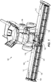
- a combine harvester 100 (or simply “combine") is shown in Fig. 1 .
- a removable header 104 is provided at a front end of the combine 100 to cut crops and feed the crops into a housing 108, or "feeder house", of the combine 100 for further harvest processing within the combine 100 (i.e., threshing of the valued crop grains from the plant stalks and separating or cleaning the crop grains from the chaff so that the crop grains alone are harvested).
- the threshing and separating can be accomplished by any one of a variety of practical mechanisms.
- the header 104 of the illustrated construction is a flexible header in which first and second wings 112 are movably supported on opposite lateral sides of a center section 116 that attaches the header 104 to the combine housing 108.
- the header 104 includes a rotatable reel 120 to engage standing crops for delivery to a table of the header 104.
- a cutterbar 124 at a forward edge of the header 104 operates (e.g., by reciprocating a plurality of overlapping knives) to cut the crop material close to the ground as it is engaged by the reel 120.
- the cutterbar 124 can be a flexible unit that allows fine terrain following throughout its length. Alternately, the cutterbar 124 can be a rigid unit that remains straight within each wing 112, allowing flexure only at the joints between the wings 112 and the center section 116.
- the header 104 is a draper header in which the table is equipped with endless belts for feeding the cut crop material into the housing 108.
- each wing 112 includes at least one side draper belt 128 operable to transmit the cut crop material inward toward the center section 116.
- the center section 116 further includes a feeder draper belt 132 operable, in a direction parallel to the combine travel direction and perpendicular to the side draper belts 128, for transmitting the cut crop material into the combine housing 108.
- Each of the wings 112 is pivotably supported by the center section 116 to allow independent movement of the two wings 112 with respect to the center section 116.
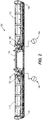
- a respective connection linkage 136 is provided between the center section 116 and each wing 112, as shown in Fig. 2 , to connect the same for pivoting motion.
- the connection linkages 136 can be provided toward a rearward end of the header 104, and a direct pivot connection may also be established toward the forward end between the center section 116 and each wing 112.
- the cutterbar 124 which spans both wings 112 and the center section 116 can flex to accommodate the pivoting movement of the wings 112 relative to the center section 116. This header 104 thus allows consistent low cutting of the crop material from the ground, even over uneven ground.
- Each wing 112 is mostly supported by a float arrangement including at least one resilient float element 140 coupled via a float linkage 142, while a small fraction of the weight of the wing 112 is applied to the ground (e.g., by a gauge wheel and/or skid 143 at the laterally outer end of the wing).
- Each resilient float element 140 is operable to produce a force output that varies with a position of the wing 112 with respect to the center section 116.
- Each of the resilient float elements 140 can be coupled in a manner that allows a relatively constant float force to be applied to the wing 112, despite changes in the actual force output of the resilient float element 140.
- each single-acting hydraulic cylinder is coupled via a hydraulic line to an accumulator 144 (e.g., a gas-charged accumulator) to facilitate the transfer of hydraulic fluid (e.g., liquid hydraulic oil) therebetween.
- the resilient float elements 140 can take other forms as well, including but not limited to one or more springs. Details of the float system and its operation are discussed in further detail below, following additional discussion of the connecting structures between the center section 116 and the wings 112.
- connection linkage 136 for coupling one of the wings 112 to the center section 116, with the understanding that the other wing 112 is supported by another connection linkage 136, which is a mirror image of the illustrated connection linkage 136 and conforms to the same description.
- the connection linkage 136 is provided as a four-bar linkage consisting of a frame portion 150 of the wing 112, a frame portion 154 of the center section 116, and two connecting links 158A, 158B therebetween.
- the two connecting links 158A, 158B are coupled at two respective pivots 160A, 160B on the frame portion 154 of the center section 116 and coupled at two respective pivots 164A, 164B on the frame portion 150 of the wing 112.
- the float linkage 142 carrying the resilient float element 140 is separately coupled between the frame portions 150, 154.
- the float linkage 142 passively responds to movement of the wing 112 through the connection linkage 136 to modify the supporting relationship between the resilient float element 140 and the wing 112.
- passive it is meant that it is merely reactive or responsive in a predetermined way, rather than actively or variably controlled.
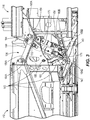
- the resilient float element 140 is extensible to vary in length between a first or lower end 170 and a second or upper end 172.
- the first and second ends 170, 172 can be provided as pivots similar to those of the connection linkage 136, but are separate and spaced from every one of the pivots 160A, 160B, 164A, 164B of the connecting links 158A, 158B. Further, only one of the first and second ends 170, 172 of the resilient float element 140 is provided in fixed position on either of the frame portions 150, 154 (i.e., the upper end 172 is fixed on the wing frame portion 150).
- a primary link 176 of the float linkage 142 has a first or lower end pivotably coupled to both the first end 170 of the resilient float element 140 and a secondary link 180 of the float linkage 142.
- a second or upper end of the primary link 176 is pivotably coupled to an additional pivot, or third pivot 184, on the frame portion 154 of the center section 116.
- the third pivot 184 is spaced above and laterally outboard (to the wing side) of both of the other pivots 160A, 160B on the frame portion 154.
- the second end 172 of the resilient float element 140 defines a pivot joint with the frame portion 150 of the wing 112 and the primary link 176, between the first and second ends of the primary link 176 (i.e., between the pivot at the lower end 170 and the third pivot 184 on the frame portion 154).
- the pivot joint is retained in the illustrated construction within an elongated hole or slot 188 in which the second end 172 of the resilient float element 140, along with the frame portion 150 secured thereto, can traverse lengthwise along a distance between ends of the slot 188.
- the ends of the slot 188 can function as travel limits (e.g., maintaining each wing 112 in a range of +/- 5 degrees from horizontal neutral alignment with the center section 116).
- the secondary link 180 of the float linkage 142 is pivotably coupled to the first end 170 of the resilient float element 140 and further pivotably coupled to the wing frame portion 150 at an additional pivot, or fourth pivot 190.
- the fourth pivot 190 lies at a position on the wing frame portion 150 between the two pivots 164A, 164B at which the two connecting links 158A, 158B are coupled.
- Fig. 3 illustrates the wing 112 in a level or neutral orientation with respect to the center section 116.
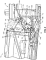
- the upper end 172 of the resilient float element 140 is positioned approximately midway between opposing ends of the slot 188 defining the pivot joint. From this position, the wing 112 is free to pivot upwardly ( Fig. 4 ) or downwardly ( Fig. 5 ) in order to follow uneven ground or terrain from which crops are to be harvested.
- the float system including the resilient float element 140 for each wing 112, provides passive wing floatation that responds to uneven ground conditions naturally, without monitoring or actively adjusting the resilient float element 140.
- a ground-contact portion of the wing 112 such as the gauge wheel or skid 143, is urged upward by the ground.
- the float system responds automatically to this disturbance by allowing upward deflection of the wing 112.
- this includes an extension of the hydraulic cylinder provided as the resilient float element 140.
- the extension increases the fluid volume within the hydraulic cylinder and allows a transfer of additional hydraulic fluid from the associated accumulator 144 into the hydraulic cylinder. The hydraulic fluid pressure, and thus the stored energy, within the resilient float element 140 is thus reduced.
- the float linkage 142 operates automatically during the wing movement to compensate for the reduction in stored energy within the resilient float element 140 in order to maintain a relatively constant float force exerted on the wing 112.
- the float linkage 142 adjusts the mechanical advantage of the resilient float element 140 to the wing 112 to offset the effect of the stored energy reduction therein, thus subduing a change in an overall wing float force applied to the wing by the resilient float element.
- the wing 112 may encounter a downslope. From the upwardly pivoted position of Fig. 4 , the wing 112 may pivot back to level or, if the downslope in the area of the wing 112 is such that the ground level is below that of the center section 116, may pivot past level to a downwardly pivoted position such as that of Fig. 5 . As the wing 112 encounters the downslope, the float system responds automatically to this disturbance by allowing downward deflection of the wing 112 as the ground reaction force resulting from the applied float force tends to decrease. In the case of a hydraulic float system as illustrated, this results in retraction or compression of the resilient float actuator 140.
- the float linkage 142 operates automatically during the wing movement to compensate for the increase in stored energy within the resilient float element 140 in order to maintain a relatively constant float force exerted on the wing 112.
- the float linkage 142 adjusts the mechanical advantage of the resilient float element 140 to the wing 112 to offset the effect of the stored energy increase therein, thus subduing a change in an overall wing float force applied to the wing by the resilient float element.
- the float force on either wing 112 is normalized throughout its pivoting movement, without a requirement for active sensing or control through outside influences or actuators. Normalization of the float force occurs naturally through the movement of the float linkage 142 that varies the effectiveness of the resilient float element 140 to support the wing 112. As disclosed, the slot 188 provides adjustment of the mechanical advantage of the resilient float element 140 in a continuous or infinite manner within its operating range. Through its design, the resilient float linkage 142 provides a means for removing the float force dependence on wing position, without complicating the basic operation of the passive resilient float element 140, which itself still generates forces that are dependent on wing position.
Landscapes
- Life Sciences & Earth Sciences (AREA)
- Environmental Sciences (AREA)
- Agricultural Machines (AREA)
- Transmission Devices (AREA)
- Harvesting Machines For Root Crops (AREA)
- Toys (AREA)
Applications Claiming Priority (1)
| Application Number | Priority Date | Filing Date | Title |
|---|---|---|---|
| US15/785,092 US10433486B2 (en) | 2017-10-16 | 2017-10-16 | System and method for wing float on a combine draper header |
Publications (2)
| Publication Number | Publication Date |
|---|---|
| EP3469876A1 true EP3469876A1 (de) | 2019-04-17 |
| EP3469876B1 EP3469876B1 (de) | 2020-07-15 |
Family
ID=63857825
Family Applications (1)
| Application Number | Title | Priority Date | Filing Date |
|---|---|---|---|
| EP18200409.3A Active EP3469876B1 (de) | 2017-10-16 | 2018-10-15 | System zur schwebenden aufhängung eines seitenflügels an einem schneidwerk eines mähdreschers |
Country Status (3)
| Country | Link |
|---|---|
| US (1) | US10433486B2 (de) |
| EP (1) | EP3469876B1 (de) |
| BR (1) | BR102018071042B1 (de) |
Cited By (1)
| Publication number | Priority date | Publication date | Assignee | Title |
|---|---|---|---|---|
| EP3446558B1 (de) | 2017-08-21 | 2020-04-08 | CNH Industrial Belgium NV | Landwirtschaftlicher erntevorsatz mit einem oder mehreren beweglichen flügelabschnitten |
Families Citing this family (20)
| Publication number | Priority date | Publication date | Assignee | Title |
|---|---|---|---|---|
| US10617059B2 (en) * | 2016-06-21 | 2020-04-14 | Macdon Industries Ltd. | Crop machine with an electronically controlled hydraulic cylinder flotation system |
| WO2019136281A1 (en) * | 2018-01-04 | 2019-07-11 | Cnh Industrial America Llc | Agricultural harvester with header having conformable portions |
| US10813289B2 (en) * | 2018-06-05 | 2020-10-27 | Deere & Company | Single top beam folding corn head mainframe |
| US10952375B2 (en) * | 2018-06-29 | 2021-03-23 | Macdon Industries Ltd | Crop header with wing balance calibration |
| US11297765B2 (en) | 2018-07-02 | 2022-04-12 | Deere & Company | Suspension compliance to reduce frame loading |
| US20220007577A1 (en) * | 2018-11-16 | 2022-01-13 | Cnh Industrial America Llc | Header with modular rigid frame |
| US11219162B2 (en) * | 2019-04-23 | 2022-01-11 | Deere & Company | Controlled header lowering on an agricultural harvester |
| US11191212B2 (en) * | 2019-04-23 | 2021-12-07 | Deere & Company | Controlled float on an agricultural harvester for header leveling |
| US11224164B2 (en) * | 2019-04-23 | 2022-01-18 | Deere & Company | Damped float response on an agricultural harvester |
| US11064654B2 (en) * | 2019-05-01 | 2021-07-20 | Deere & Company | Float adjustment |
| CA190293S (en) * | 2019-05-09 | 2021-02-26 | Deere & Co | Fender for an agricultural machine |
| US11019770B2 (en) * | 2019-05-28 | 2021-06-01 | Deere & Company | Harvester wing leveling configuration |
| US11627701B2 (en) * | 2019-10-31 | 2023-04-18 | Deere & Company | Agricultural header with flexible joint |
| US11375658B2 (en) * | 2019-12-23 | 2022-07-05 | Cnh Industrial America Llc | System and method for leveling a cutter bar of a harvester |
| US11234368B2 (en) * | 2019-12-23 | 2022-02-01 | Cnh Industrial America Llc | Cutter bar assembly for a harvester |
| US12396387B2 (en) | 2021-07-20 | 2025-08-26 | Deere & Company | Automated lockout system for header |
| US12396393B2 (en) | 2021-07-20 | 2025-08-26 | Deer & Company | Automated lockout system for header |
| US12402561B2 (en) | 2021-07-20 | 2025-09-02 | Deere & Company | Automated lockout system for header |
| US20240306543A1 (en) * | 2023-03-13 | 2024-09-19 | Cnh Industrial America Llc | Auger assembly for an agricultural header |
| US20240306546A1 (en) * | 2023-03-13 | 2024-09-19 | Cnh Industrial America Llc | Flexible infeed deck for an agricultural header |
Citations (3)
| Publication number | Priority date | Publication date | Assignee | Title |
|---|---|---|---|---|
| US20080295473A1 (en) * | 2007-06-04 | 2008-12-04 | Claas Selbstfahrende Erntemaschinen Gmbh | Winged header apparatus and method for a combine |
| EP3066910A1 (de) * | 2015-03-13 | 2016-09-14 | CNH Industrial Belgium nv | Faltmechanismus für breites weizenschneidwerk |
| EP3153004A1 (de) | 2015-10-05 | 2017-04-12 | Carl Geringhoff GmbH & Co. KG | Schneidwerk mit verstellbarer seitenrahmenentlastung |
Family Cites Families (56)
| Publication number | Priority date | Publication date | Assignee | Title |
|---|---|---|---|---|
| US2608041A (en) | 1947-01-24 | 1952-08-26 | Case Co J I | Conveying means for harvester headers |
| NL6414183A (de) | 1964-12-05 | 1966-06-06 | ||
| NL6903371A (de) | 1969-03-05 | 1970-09-08 | ||
| US4487004A (en) * | 1983-06-03 | 1984-12-11 | Kejr Melvin P | Combine harvester apparatus |
| CA2110775C (en) | 1993-12-06 | 1999-03-02 | Gregory J. Honey | A feeder adapter for mounting a combine header to a feeder housing of a combine |
| DE19523255A1 (de) | 1995-06-27 | 1997-01-02 | Claas Saulgau Gmbh | Erntevorsatz an landwirtschaftlichen Arbeitsmaschinen zum Aufnehmen und Weiterführen von Halmfrüchten, beispielsweise Maispflanzen |
| US5577563A (en) | 1995-07-27 | 1996-11-26 | Holen; Kurt | Stack-folding toolbar with floating wings |
| US5673543A (en) | 1996-01-04 | 1997-10-07 | Byron Enterprises, Inc | Foldable corn head with unobstructed auger |
| US5724798A (en) | 1996-07-08 | 1998-03-10 | Byron Enterprises Inc. | Latch for a folding corn head |
| US6003615A (en) | 1998-08-19 | 1999-12-21 | Moore; Paul O. | Stacking tool bar including a wing flex structure |
| US6202397B1 (en) | 1999-05-27 | 2001-03-20 | Deere & Company | Draper belt tensioning mechanism for a harvesting platform |
| DE10039097A1 (de) | 2000-08-07 | 2002-02-21 | Claas Saulgau Gmbh | Verfahren und Vorrichtung zum Schwenken der Abteiler von mehrteiligen landwirtschaftlichen Erntemaschinen |
| CA2387898C (en) | 2001-06-18 | 2005-01-11 | Macdon Industries Ltd. | Multi-section header with flexible crop cutting knife |
| HUP0300512A2 (hu) | 2002-03-28 | 2004-09-28 | Claas Saulgau Gmbh | Kaszáló berendezés |
| DE10221983A1 (de) | 2002-05-17 | 2003-11-27 | Kemper Gmbh Maschf | Erntevorsatz |
| DE10250337A1 (de) | 2002-10-29 | 2004-05-19 | Maschinenfabrik Kemper Gmbh & Co. Kg | Verstelleinrichtung für einen Erntevorsatz |
| US6865871B2 (en) | 2003-07-14 | 2005-03-15 | Macdon Industries Ltd. | Crop feed arrangement for the header of a combine harvester |
| US7168226B2 (en) | 2004-03-31 | 2007-01-30 | Cnh America Llc | Independent hydraulic header lift and flotation system |
| CA2510883C (en) | 2004-06-16 | 2013-05-21 | Macdon Industries Ltd. | Reversible feed roller with radially extendible fingers |
| US7467668B2 (en) | 2005-03-31 | 2008-12-23 | Kimball Von D | Transport lock joint for stack fold toolbar |
| US20070193243A1 (en) | 2006-02-10 | 2007-08-23 | Schmidt James R | Combine Harvester Draper Header Having Flexible Cutterbar |
| US20080276590A1 (en) | 2006-02-10 | 2008-11-13 | Agco Corporation | Flexible draper and cutter bar with tilt arm for cutterbar drive |
| US7540130B2 (en) | 2006-03-02 | 2009-06-02 | Deere & Company | Height control for a multi-section cutting platform in an agricultural harvesting machine |
| US7918076B2 (en) | 2006-09-25 | 2011-04-05 | Macdon Industries Ltd. | Device for maintaining wing balance on a multi-section header |
| CA2572274C (en) | 2006-12-29 | 2014-05-27 | Honey Bee Manufacturing Ltd. | Rock trap for combine header |
| US7587885B2 (en) | 2007-06-04 | 2009-09-15 | Claas Selbstfahrende Emtemaschinen Gmbh | Central auger crop feed system for a harvester |
| US7921627B2 (en) | 2008-05-09 | 2011-04-12 | Agco Corporation | Interlocking belt guards for a draper header |
| US7788891B2 (en) | 2008-06-27 | 2010-09-07 | Deere & Company | Endless belt mounting configuration for an agricultural harvester |
| US8281561B2 (en) | 2010-08-17 | 2012-10-09 | Deere & Company | Flexible draper belt drive for an agricultural harvesting machine |
| DE102010037131A1 (de) | 2010-08-24 | 2012-03-01 | Claas Selbstfahrende Erntemaschinen Gmbh | Schneidwerk |
| US7992372B1 (en) * | 2010-09-16 | 2011-08-09 | Deere & Company | Draper platform with breakaway joint |
| US8087224B1 (en) | 2010-09-16 | 2012-01-03 | Deere & Company | Flexible draper platform with pivot geometry |
| US8336280B2 (en) | 2011-05-20 | 2012-12-25 | Deere & Company | Pivoting center conveyor for draper platform |
| US8544250B2 (en) | 2011-10-25 | 2013-10-01 | Deere & Company | Draper platform with center conveyor and method of replacing the center conveyor belt |
| ITPD20120242A1 (it) | 2012-08-06 | 2014-02-07 | Cressoni S P A Flli | Testata ripiegabile per macchina spannocchiatrice e/o mietitrebbia e metodo di ripiegatura di una testata di macchina spannocchiatrice e/o mietitrebbia |
| US8695315B2 (en) | 2012-08-09 | 2014-04-15 | Deere & Company | Draper header with pivoting side draper conveyors |
| US9198353B2 (en) * | 2012-09-20 | 2015-12-01 | Deere & Company | Hinged row crop harvesting head |
| US9072222B2 (en) | 2012-09-20 | 2015-07-07 | Deere & Company | Self-centering cover for hinged row crop harvesting head |
| DE102013100322A1 (de) | 2013-01-14 | 2014-07-17 | Claas Selbstfahrende Erntemaschinen Gmbh | Schneidwerk |
| US9198349B2 (en) | 2013-07-12 | 2015-12-01 | Deere & Company | Articulated harvesting head ground force control circuit |
| US9144199B2 (en) | 2013-08-30 | 2015-09-29 | Deere & Company | Articulated harvesting head load sensor arrangement |
| DE102014009161B4 (de) | 2014-06-25 | 2023-01-26 | Carl Geringhoff Gmbh & Co. Kg | Schneidwerk mit Mittelteil und dazu verstellbaren Seitenteilen |
| DE102014216112A1 (de) | 2014-08-13 | 2016-02-18 | Walter Schmid | Selbstfahrende Erntemaschine |
| US9788486B2 (en) | 2014-12-30 | 2017-10-17 | Agco Corporation | Grain header with swathing and chopping capability |
| US9668412B2 (en) | 2015-05-01 | 2017-06-06 | Deere & Company | Harvesting head height control circuit |
| US20160360699A1 (en) | 2015-06-10 | 2016-12-15 | Jose Luis Allochis | Conveyor belt tensing apparatus for a harvesting header |
| DE102015118143A1 (de) | 2015-10-23 | 2017-04-27 | Arnold Jäger Holding GmbH | Nockenriemen, insbesondere für landwirtschaftliche Maschinen |
| BE1023925B1 (nl) | 2016-03-01 | 2017-09-13 | Cnh Industrial Belgium Nv | Toevoertoestel voor maaidorser |
| BE1024333B1 (nl) | 2016-06-23 | 2018-02-01 | Cnh Industrial Belgium Nv | Maaibordsteun voor een oogstmachine |
| US10070575B2 (en) | 2016-08-05 | 2018-09-11 | Cnh Industrial America Llc | Agricultural machine with folding header |
| US20180070526A1 (en) | 2016-09-13 | 2018-03-15 | Cnh Industrial Canada, Ltd. | Apparatus and method to minimize transport dimensions of agricultural implements |
| DE102016118174A1 (de) | 2016-09-26 | 2018-03-29 | Claas Selbstfahrende Erntemaschinen Gmbh | Schneidwerk |
| US10375881B2 (en) | 2017-05-23 | 2019-08-13 | Cnh Industrial America Llc | Agricultural machine with sectional header |
| US10299437B2 (en) | 2017-07-17 | 2019-05-28 | Cnh Industrial America Llc | Header for an agricultural vehicle with deformable supports |
| US10820509B2 (en) | 2017-08-08 | 2020-11-03 | Cnh Industrial America Llc | Foldable corn head |
| US10433483B2 (en) * | 2017-08-21 | 2019-10-08 | Cnh Industrial America Llc | Agricultural header with one or more movable wing sections |
-
2017
- 2017-10-16 US US15/785,092 patent/US10433486B2/en active Active
-
2018
- 2018-10-11 BR BR102018071042-7A patent/BR102018071042B1/pt active IP Right Grant
- 2018-10-15 EP EP18200409.3A patent/EP3469876B1/de active Active
Patent Citations (3)
| Publication number | Priority date | Publication date | Assignee | Title |
|---|---|---|---|---|
| US20080295473A1 (en) * | 2007-06-04 | 2008-12-04 | Claas Selbstfahrende Erntemaschinen Gmbh | Winged header apparatus and method for a combine |
| EP3066910A1 (de) * | 2015-03-13 | 2016-09-14 | CNH Industrial Belgium nv | Faltmechanismus für breites weizenschneidwerk |
| EP3153004A1 (de) | 2015-10-05 | 2017-04-12 | Carl Geringhoff GmbH & Co. KG | Schneidwerk mit verstellbarer seitenrahmenentlastung |
Cited By (4)
| Publication number | Priority date | Publication date | Assignee | Title |
|---|---|---|---|---|
| EP3446558B1 (de) | 2017-08-21 | 2020-04-08 | CNH Industrial Belgium NV | Landwirtschaftlicher erntevorsatz mit einem oder mehreren beweglichen flügelabschnitten |
| US11224165B2 (en) | 2017-08-21 | 2022-01-18 | Cnh Industrial America Llc | Agricultural header with one or more movable wing sections |
| EP3446558B2 (de) † | 2017-08-21 | 2023-03-29 | CNH Industrial Belgium NV | Landwirtschaftlicher erntevorsatz mit einem oder mehreren beweglichen flügelabschnitten |
| US11930739B2 (en) | 2017-08-21 | 2024-03-19 | Cnh Industrial America Llc | Agricultural header with one or more movable wing sections |
Also Published As
| Publication number | Publication date |
|---|---|
| BR102018071042A2 (pt) | 2019-06-04 |
| US10433486B2 (en) | 2019-10-08 |
| US20190110402A1 (en) | 2019-04-18 |
| EP3469876B1 (de) | 2020-07-15 |
| BR102018071042B1 (pt) | 2023-11-14 |
Similar Documents
| Publication | Publication Date | Title |
|---|---|---|
| EP3469876B1 (de) | System zur schwebenden aufhängung eines seitenflügels an einem schneidwerk eines mähdreschers | |
| EP3473076B1 (de) | Selbstständiger mähdrescherschneidwerkflügelnivellierer | |
| US7726111B2 (en) | Suspension system for a belt pickup header in an agricultural harvester | |
| EP1401256B1 (de) | Mehrteiliges schneidwerk mit flexiblem gewächsschneidemesser | |
| US10426088B2 (en) | Center feed assembly for a draper | |
| EP3466241B1 (de) | Landwirtschaftlicher erntekopf mit schwimmerarmschwenkpunkt unterhalb der hubmesser | |
| AU2002257470A1 (en) | Multi-section header with flexible crop cutting knife | |
| US20170013778A1 (en) | Header Tilt Mechanism | |
| CN112616445B (zh) | 基于机器俯仰或地形调节收割台浮动系统的方法及其系统 | |
| EP3897094B1 (de) | Armanordnung eines landwirtschaftlichen erntevorsatzes | |
| EP3305058B1 (de) | Landwirtschaftlicher erntevorsatz mit dem messerwerk folgender haspel | |
| US10375882B2 (en) | Multi-sectional header frame | |
| US11553645B2 (en) | Flex arm air bag linkage | |
| EP3657932B1 (de) | Transportbandanordnung für eine landwirtschaftliche erntemaschine | |
| EP3998845B1 (de) | Gehäuseanordnungen eines förderers, landwirtschaftliche erntemaschinen und verfahren zum verbinden von erntevorsätzen mit landwirtschaftlichen erntemaschinen | |
| US20230240179A1 (en) | Agricultural header float arm system | |
| EP3815505B1 (de) | Torsionsausgeglichener erntevorsatz | |
| US20240373783A1 (en) | Linkage for cutterbar of header for agricultural vehicle |
Legal Events
| Date | Code | Title | Description |
|---|---|---|---|
| PUAI | Public reference made under article 153(3) epc to a published international application that has entered the european phase |
Free format text: ORIGINAL CODE: 0009012 |
|
| STAA | Information on the status of an ep patent application or granted ep patent |
Free format text: STATUS: THE APPLICATION HAS BEEN PUBLISHED |
|
| AK | Designated contracting states |
Kind code of ref document: A1 Designated state(s): AL AT BE BG CH CY CZ DE DK EE ES FI FR GB GR HR HU IE IS IT LI LT LU LV MC MK MT NL NO PL PT RO RS SE SI SK SM TR |
|
| AX | Request for extension of the european patent |
Extension state: BA ME |
|
| TPAC | Observations filed by third parties |
Free format text: ORIGINAL CODE: EPIDOSNTIPA |
|
| STAA | Information on the status of an ep patent application or granted ep patent |
Free format text: STATUS: REQUEST FOR EXAMINATION WAS MADE |
|
| 17P | Request for examination filed |
Effective date: 20191017 |
|
| RBV | Designated contracting states (corrected) |
Designated state(s): AL AT BE BG CH CY CZ DE DK EE ES FI FR GB GR HR HU IE IS IT LI LT LU LV MC MK MT NL NO PL PT RO RS SE SI SK SM TR |
|
| GRAP | Despatch of communication of intention to grant a patent |
Free format text: ORIGINAL CODE: EPIDOSNIGR1 |
|
| STAA | Information on the status of an ep patent application or granted ep patent |
Free format text: STATUS: GRANT OF PATENT IS INTENDED |
|
| INTG | Intention to grant announced |
Effective date: 20200214 |
|
| GRAS | Grant fee paid |
Free format text: ORIGINAL CODE: EPIDOSNIGR3 |
|
| GRAA | (expected) grant |
Free format text: ORIGINAL CODE: 0009210 |
|
| STAA | Information on the status of an ep patent application or granted ep patent |
Free format text: STATUS: THE PATENT HAS BEEN GRANTED |
|
| AK | Designated contracting states |
Kind code of ref document: B1 Designated state(s): AL AT BE BG CH CY CZ DE DK EE ES FI FR GB GR HR HU IE IS IT LI LT LU LV MC MK MT NL NO PL PT RO RS SE SI SK SM TR |
|
| REG | Reference to a national code |
Ref country code: CH Ref legal event code: EP Ref country code: GB Ref legal event code: FG4D |
|
| REG | Reference to a national code |
Ref country code: IE Ref legal event code: FG4D |
|
| REG | Reference to a national code |
Ref country code: DE Ref legal event code: R096 Ref document number: 602018006042 Country of ref document: DE |
|
| REG | Reference to a national code |
Ref country code: AT Ref legal event code: REF Ref document number: 1289928 Country of ref document: AT Kind code of ref document: T Effective date: 20200815 |
|
| REG | Reference to a national code |
Ref country code: LT Ref legal event code: MG4D |
|
| REG | Reference to a national code |
Ref country code: AT Ref legal event code: MK05 Ref document number: 1289928 Country of ref document: AT Kind code of ref document: T Effective date: 20200715 |
|
| REG | Reference to a national code |
Ref country code: NL Ref legal event code: MP Effective date: 20200715 |
|
| PG25 | Lapsed in a contracting state [announced via postgrant information from national office to epo] |
Ref country code: LT Free format text: LAPSE BECAUSE OF FAILURE TO SUBMIT A TRANSLATION OF THE DESCRIPTION OR TO PAY THE FEE WITHIN THE PRESCRIBED TIME-LIMIT Effective date: 20200715 Ref country code: ES Free format text: LAPSE BECAUSE OF FAILURE TO SUBMIT A TRANSLATION OF THE DESCRIPTION OR TO PAY THE FEE WITHIN THE PRESCRIBED TIME-LIMIT Effective date: 20200715 Ref country code: PT Free format text: LAPSE BECAUSE OF FAILURE TO SUBMIT A TRANSLATION OF THE DESCRIPTION OR TO PAY THE FEE WITHIN THE PRESCRIBED TIME-LIMIT Effective date: 20201116 Ref country code: BG Free format text: LAPSE BECAUSE OF FAILURE TO SUBMIT A TRANSLATION OF THE DESCRIPTION OR TO PAY THE FEE WITHIN THE PRESCRIBED TIME-LIMIT Effective date: 20201015 Ref country code: SE Free format text: LAPSE BECAUSE OF FAILURE TO SUBMIT A TRANSLATION OF THE DESCRIPTION OR TO PAY THE FEE WITHIN THE PRESCRIBED TIME-LIMIT Effective date: 20200715 Ref country code: AT Free format text: LAPSE BECAUSE OF FAILURE TO SUBMIT A TRANSLATION OF THE DESCRIPTION OR TO PAY THE FEE WITHIN THE PRESCRIBED TIME-LIMIT Effective date: 20200715 Ref country code: HR Free format text: LAPSE BECAUSE OF FAILURE TO SUBMIT A TRANSLATION OF THE DESCRIPTION OR TO PAY THE FEE WITHIN THE PRESCRIBED TIME-LIMIT Effective date: 20200715 Ref country code: GR Free format text: LAPSE BECAUSE OF FAILURE TO SUBMIT A TRANSLATION OF THE DESCRIPTION OR TO PAY THE FEE WITHIN THE PRESCRIBED TIME-LIMIT Effective date: 20201016 Ref country code: NO Free format text: LAPSE BECAUSE OF FAILURE TO SUBMIT A TRANSLATION OF THE DESCRIPTION OR TO PAY THE FEE WITHIN THE PRESCRIBED TIME-LIMIT Effective date: 20201015 Ref country code: FI Free format text: LAPSE BECAUSE OF FAILURE TO SUBMIT A TRANSLATION OF THE DESCRIPTION OR TO PAY THE FEE WITHIN THE PRESCRIBED TIME-LIMIT Effective date: 20200715 |
|
| PG25 | Lapsed in a contracting state [announced via postgrant information from national office to epo] |
Ref country code: RS Free format text: LAPSE BECAUSE OF FAILURE TO SUBMIT A TRANSLATION OF THE DESCRIPTION OR TO PAY THE FEE WITHIN THE PRESCRIBED TIME-LIMIT Effective date: 20200715 Ref country code: LV Free format text: LAPSE BECAUSE OF FAILURE TO SUBMIT A TRANSLATION OF THE DESCRIPTION OR TO PAY THE FEE WITHIN THE PRESCRIBED TIME-LIMIT Effective date: 20200715 Ref country code: PL Free format text: LAPSE BECAUSE OF FAILURE TO SUBMIT A TRANSLATION OF THE DESCRIPTION OR TO PAY THE FEE WITHIN THE PRESCRIBED TIME-LIMIT Effective date: 20200715 Ref country code: IS Free format text: LAPSE BECAUSE OF FAILURE TO SUBMIT A TRANSLATION OF THE DESCRIPTION OR TO PAY THE FEE WITHIN THE PRESCRIBED TIME-LIMIT Effective date: 20201115 |
|
| PG25 | Lapsed in a contracting state [announced via postgrant information from national office to epo] |
Ref country code: NL Free format text: LAPSE BECAUSE OF FAILURE TO SUBMIT A TRANSLATION OF THE DESCRIPTION OR TO PAY THE FEE WITHIN THE PRESCRIBED TIME-LIMIT Effective date: 20200715 |
|
| REG | Reference to a national code |
Ref country code: DE Ref legal event code: R026 Ref document number: 602018006042 Country of ref document: DE |
|
| PLBI | Opposition filed |
Free format text: ORIGINAL CODE: 0009260 |
|
| PG25 | Lapsed in a contracting state [announced via postgrant information from national office to epo] |
Ref country code: CZ Free format text: LAPSE BECAUSE OF FAILURE TO SUBMIT A TRANSLATION OF THE DESCRIPTION OR TO PAY THE FEE WITHIN THE PRESCRIBED TIME-LIMIT Effective date: 20200715 Ref country code: DK Free format text: LAPSE BECAUSE OF FAILURE TO SUBMIT A TRANSLATION OF THE DESCRIPTION OR TO PAY THE FEE WITHIN THE PRESCRIBED TIME-LIMIT Effective date: 20200715 Ref country code: RO Free format text: LAPSE BECAUSE OF FAILURE TO SUBMIT A TRANSLATION OF THE DESCRIPTION OR TO PAY THE FEE WITHIN THE PRESCRIBED TIME-LIMIT Effective date: 20200715 Ref country code: EE Free format text: LAPSE BECAUSE OF FAILURE TO SUBMIT A TRANSLATION OF THE DESCRIPTION OR TO PAY THE FEE WITHIN THE PRESCRIBED TIME-LIMIT Effective date: 20200715 Ref country code: SM Free format text: LAPSE BECAUSE OF FAILURE TO SUBMIT A TRANSLATION OF THE DESCRIPTION OR TO PAY THE FEE WITHIN THE PRESCRIBED TIME-LIMIT Effective date: 20200715 Ref country code: IT Free format text: LAPSE BECAUSE OF FAILURE TO SUBMIT A TRANSLATION OF THE DESCRIPTION OR TO PAY THE FEE WITHIN THE PRESCRIBED TIME-LIMIT Effective date: 20200715 |
|
| PLAX | Notice of opposition and request to file observation + time limit sent |
Free format text: ORIGINAL CODE: EPIDOSNOBS2 |
|
| 26 | Opposition filed |
Opponent name: CARL GERINGHOFF GMBH & CO. KG Effective date: 20210413 |
|
| PG25 | Lapsed in a contracting state [announced via postgrant information from national office to epo] |
Ref country code: AL Free format text: LAPSE BECAUSE OF FAILURE TO SUBMIT A TRANSLATION OF THE DESCRIPTION OR TO PAY THE FEE WITHIN THE PRESCRIBED TIME-LIMIT Effective date: 20200715 |
|
| PG25 | Lapsed in a contracting state [announced via postgrant information from national office to epo] |
Ref country code: MC Free format text: LAPSE BECAUSE OF FAILURE TO SUBMIT A TRANSLATION OF THE DESCRIPTION OR TO PAY THE FEE WITHIN THE PRESCRIBED TIME-LIMIT Effective date: 20200715 Ref country code: SK Free format text: LAPSE BECAUSE OF FAILURE TO SUBMIT A TRANSLATION OF THE DESCRIPTION OR TO PAY THE FEE WITHIN THE PRESCRIBED TIME-LIMIT Effective date: 20200715 Ref country code: LU Free format text: LAPSE BECAUSE OF NON-PAYMENT OF DUE FEES Effective date: 20201015 |
|
| REG | Reference to a national code |
Ref country code: BE Ref legal event code: MM Effective date: 20201031 |
|
| PG25 | Lapsed in a contracting state [announced via postgrant information from national office to epo] |
Ref country code: FR Free format text: LAPSE BECAUSE OF NON-PAYMENT OF DUE FEES Effective date: 20201031 |
|
| PG25 | Lapsed in a contracting state [announced via postgrant information from national office to epo] |
Ref country code: SI Free format text: LAPSE BECAUSE OF FAILURE TO SUBMIT A TRANSLATION OF THE DESCRIPTION OR TO PAY THE FEE WITHIN THE PRESCRIBED TIME-LIMIT Effective date: 20200715 Ref country code: BE Free format text: LAPSE BECAUSE OF NON-PAYMENT OF DUE FEES Effective date: 20201031 |
|
| PLBB | Reply of patent proprietor to notice(s) of opposition received |
Free format text: ORIGINAL CODE: EPIDOSNOBS3 |
|
| PG25 | Lapsed in a contracting state [announced via postgrant information from national office to epo] |
Ref country code: IE Free format text: LAPSE BECAUSE OF NON-PAYMENT OF DUE FEES Effective date: 20201015 |
|
| PLBP | Opposition withdrawn |
Free format text: ORIGINAL CODE: 0009264 |
|
| PLBD | Termination of opposition procedure: decision despatched |
Free format text: ORIGINAL CODE: EPIDOSNOPC1 |
|
| REG | Reference to a national code |
Ref country code: DE Ref legal event code: R100 Ref document number: 602018006042 Country of ref document: DE |
|
| REG | Reference to a national code |
Ref country code: CH Ref legal event code: PL |
|
| PG25 | Lapsed in a contracting state [announced via postgrant information from national office to epo] |
Ref country code: TR Free format text: LAPSE BECAUSE OF FAILURE TO SUBMIT A TRANSLATION OF THE DESCRIPTION OR TO PAY THE FEE WITHIN THE PRESCRIBED TIME-LIMIT Effective date: 20200715 Ref country code: MT Free format text: LAPSE BECAUSE OF FAILURE TO SUBMIT A TRANSLATION OF THE DESCRIPTION OR TO PAY THE FEE WITHIN THE PRESCRIBED TIME-LIMIT Effective date: 20200715 Ref country code: CY Free format text: LAPSE BECAUSE OF FAILURE TO SUBMIT A TRANSLATION OF THE DESCRIPTION OR TO PAY THE FEE WITHIN THE PRESCRIBED TIME-LIMIT Effective date: 20200715 |
|
| PG25 | Lapsed in a contracting state [announced via postgrant information from national office to epo] |
Ref country code: MK Free format text: LAPSE BECAUSE OF FAILURE TO SUBMIT A TRANSLATION OF THE DESCRIPTION OR TO PAY THE FEE WITHIN THE PRESCRIBED TIME-LIMIT Effective date: 20200715 |
|
| PLBM | Termination of opposition procedure: date of legal effect published |
Free format text: ORIGINAL CODE: 0009276 |
|
| PG25 | Lapsed in a contracting state [announced via postgrant information from national office to epo] |
Ref country code: LI Free format text: LAPSE BECAUSE OF NON-PAYMENT OF DUE FEES Effective date: 20211031 Ref country code: CH Free format text: LAPSE BECAUSE OF NON-PAYMENT OF DUE FEES Effective date: 20211031 |
|
| 27C | Opposition proceedings terminated |
Effective date: 20220514 |
|
| GBPC | Gb: european patent ceased through non-payment of renewal fee |
Effective date: 20221015 |
|
| PG25 | Lapsed in a contracting state [announced via postgrant information from national office to epo] |
Ref country code: GB Free format text: LAPSE BECAUSE OF NON-PAYMENT OF DUE FEES Effective date: 20221015 |
|
| PGFP | Annual fee paid to national office [announced via postgrant information from national office to epo] |
Ref country code: DE Payment date: 20250919 Year of fee payment: 8 |