EP3446558B2 - Landwirtschaftlicher erntevorsatz mit einem oder mehreren beweglichen flügelabschnitten - Google Patents
Landwirtschaftlicher erntevorsatz mit einem oder mehreren beweglichen flügelabschnitten Download PDFInfo
- Publication number
- EP3446558B2 EP3446558B2 EP18186329.1A EP18186329A EP3446558B2 EP 3446558 B2 EP3446558 B2 EP 3446558B2 EP 18186329 A EP18186329 A EP 18186329A EP 3446558 B2 EP3446558 B2 EP 3446558B2
- Authority
- EP
- European Patent Office
- Prior art keywords
- bar
- section
- wing
- main
- segment
- Prior art date
- Legal status (The legal status is an assumption and is not a legal conclusion. Google has not performed a legal analysis and makes no representation as to the accuracy of the status listed.)
- Active
Links
Images


Classifications
-
- A—HUMAN NECESSITIES
- A01—AGRICULTURE; FORESTRY; ANIMAL HUSBANDRY; HUNTING; TRAPPING; FISHING
- A01D—HARVESTING; MOWING
- A01D45/00—Harvesting of standing crops
- A01D45/02—Harvesting of standing crops of maize, i.e. kernel harvesting
- A01D45/021—Cornheaders
-
- A—HUMAN NECESSITIES
- A01—AGRICULTURE; FORESTRY; ANIMAL HUSBANDRY; HUNTING; TRAPPING; FISHING
- A01B—SOIL WORKING IN AGRICULTURE OR FORESTRY; PARTS, DETAILS, OR ACCESSORIES OF AGRICULTURAL MACHINES OR IMPLEMENTS, IN GENERAL
- A01B73/00—Means or arrangements to facilitate transportation of agricultural machines or implements, e.g. folding frames to reduce overall width
- A01B73/02—Folding frames
- A01B73/06—Folding frames foldable about a vertical axis
-
- A—HUMAN NECESSITIES
- A01—AGRICULTURE; FORESTRY; ANIMAL HUSBANDRY; HUNTING; TRAPPING; FISHING
- A01D—HARVESTING; MOWING
- A01D41/00—Combines, i.e. harvesters or mowers combined with threshing devices
- A01D41/06—Combines with headers
-
- A—HUMAN NECESSITIES
- A01—AGRICULTURE; FORESTRY; ANIMAL HUSBANDRY; HUNTING; TRAPPING; FISHING
- A01D—HARVESTING; MOWING
- A01D41/00—Combines, i.e. harvesters or mowers combined with threshing devices
- A01D41/12—Details of combines
- A01D41/127—Control or measuring arrangements specially adapted for combines
-
- A—HUMAN NECESSITIES
- A01—AGRICULTURE; FORESTRY; ANIMAL HUSBANDRY; HUNTING; TRAPPING; FISHING
- A01D—HARVESTING; MOWING
- A01D41/00—Combines, i.e. harvesters or mowers combined with threshing devices
- A01D41/12—Details of combines
- A01D41/14—Mowing tables
-
- A—HUMAN NECESSITIES
- A01—AGRICULTURE; FORESTRY; ANIMAL HUSBANDRY; HUNTING; TRAPPING; FISHING
- A01D—HARVESTING; MOWING
- A01D41/00—Combines, i.e. harvesters or mowers combined with threshing devices
- A01D41/12—Details of combines
- A01D41/14—Mowing tables
- A01D41/141—Automatic header control
-
- A—HUMAN NECESSITIES
- A01—AGRICULTURE; FORESTRY; ANIMAL HUSBANDRY; HUNTING; TRAPPING; FISHING
- A01D—HARVESTING; MOWING
- A01D41/00—Combines, i.e. harvesters or mowers combined with threshing devices
- A01D41/12—Details of combines
- A01D41/14—Mowing tables
- A01D41/144—Foldable headers
-
- A—HUMAN NECESSITIES
- A01—AGRICULTURE; FORESTRY; ANIMAL HUSBANDRY; HUNTING; TRAPPING; FISHING
- A01D—HARVESTING; MOWING
- A01D69/00—Driving mechanisms or parts thereof for harvesters or mowers
Definitions
- the present invention pertains to an agricultural vehicle and, more specifically, to an agricultural vehicle with a header having one or more movable wing sections.
- a combine An agricultural harvester known as a "combine” is historically termed such because it combines multiple harvesting functions with a single harvesting unit, such as picking, threshing, separating and cleaning.
- a combine includes a header which removes the crop from a field, and a feeder housing which transports the crop matter into a threshing rotor.
- the threshing rotor rotates within a perforated housing, which may be in the form of adjustable concaves and performs a threshing operation on the crop to remove the grain.
- a perforated housing which may be in the form of adjustable concaves and performs a threshing operation on the crop to remove the grain.
- a cleaning fan blows air through the sieves to discharge chaff and other debris toward the rear of the combine.
- Non-grain crop material such as straw from the threshing section proceeds through a residue system, which may utilize a straw chopper to process the non-grain material and direct it out the rear of the combine.
- a residue system which may utilize a straw chopper to process the non-grain material and direct it out the rear of the combine.
- the combine When the grain tank becomes full, the combine is positioned adjacent a vehicle into which the grain is to be unloaded, such as a semi-trailer, gravity box, straight truck, or the like; and an unloading system on the combine is actuated to transfer the grain into the vehicle.
- the header of the combine harvester may be equipped with a cutter bar assembly having many sharp cutting elements that reciprocate sidewardly, relative to a forward direction of travel, to sever the crop material from the field before entering the feeder housing.
- the header may include a rotating reel with tines or the like to sweep crop material toward the cutting elements.
- cutter bars can flex during harvesting. Flexure of the cutter bar(s) can help compensate for terrain irregularity encountered by the header during travel across a field. Some flexible cutter bars may allow, for example, 3 inches of travel in either direction from a normal, unflexed position, allowing the flexible cutter bar to compensate for up to 6 inches of ground irregularity across a width of the header.
- headers may have a width of 45 feet or more. Increasing the width of the header has been done in a variety of ways, including having a main section of the header which couples to one or more wing sections.
- an agricultural header including: a main section including a main frame carrying a cutting element; at least one wing section pivotably coupled to the main section and including a wing frame, the wing frame supporting the cutting element such that pivotable movement of the at least one wing section causes a corresponding flexure of the cutting element; and a linkage pivotably coupling the at least one wing section to the main section, the linkage including an upper bar and a lower bar which are both coupled to the main frame and the wing frame.
- One possible advantage of exemplary embodiments formed in accordance with the present invention is the pivoting behavior of the at least one wing section relative to the main section can be varied by altering the configuration and orientation of the upper bar and lower bar of the linkage.
- orientation of the at least one segment section can be controlled by an actuator linked to the bars or segment section to alter the ground following behavior of the header.
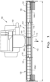
- an exemplary embodiment of an agricultural vehicle 100 in the form of a combine harvester which generally includes a chassis 102 and an agricultural header 110 carried by the chassis 102, in accordance with an exemplary embodiment of the present invention.
- the combine harvester 100 will include additional systems for the separation and handling of collected crop material, but these additional systems are omitted from view for brevity of description.
- the header 110 described and illustrated herein does not necessarily need to be included on a combine harvester, but can be incorporated in other agricultural vehicles such as mowers.
- the header 110 includes a main section 111 with a main frame 112 carrying a cutting element 113 with sharpened edges 114 to cut crop material as the vehicle 100 travels in a forward direction, denoted by arrow F.
- the cutting element 113 is a cutter bar, but other types of cutting elements can also be included in place of the cutter bar 113.
- the header 110 is shown in the exemplary embodiment of a grain header for harvesting grain, in some exemplary embodiments formed according to the present the header can be in the form of a corn header equipped with one or more appropriate cutting elements for harvesting corn.
- the main frame 112 can be rigidly connected to the chassis 102 at a mount 103, but this is an optional configuration.
- the main section 111 can have a pair of opposed lateral ends 115 and 116, with a wing section 120 and 130 pivotably coupled to each of the lateral ends 115, 116, respectively.
- "pivotably coupled” signifies that each wing section 120, 130 can be connected to its respective lateral end 120, 130 so the wing sections 120, 130 can pivot during travel of the vehicle 100, which is described further herein.
- the wing sections 120, 130 each have a respective wing frame 121, 131 which support the cutter bar 113, as shown, so pivotable movement of the wing sections 120, 130 cause flexing of the cutter bar 113 to follow the ground, as will be described further herein.
- the main section 111 can define a main section length MSL which may be greater than a respective wing section length WSL1, WSL2 of the wing sections 120, 130; in some exemplary embodiments, one or more of the wing section lengths WSL1, WSL2 may be greater than the main section length MSL.
- WSL1, WSL2 may be greater than the main section length MSL.
- two wing sections 120, 130 are shown and described herein, it should be appreciated that the vehicle 100 may only include one wing section or more than two wing sections, if desired.
- FIG. 2 an exemplary embodiment of a linkage 200 pivotably coupling one of the wing sections 120, 130 to the main section 111 is shown. While not shown in FIG. 2 , another linkage similar to the linkage 200 shown in FIGS. 2-3 , or other linkage, can be used to pivotably couple the wing section 130 to the main section 110.
- the linkage 200 includes an upper bar 201 and a lower bar 202 which are both coupled to the wing frame 121 and the main frame 112.
- the upper bar 201 can be coupled to an upper main pivot 216 of the main section 111 and an upper wing pivot 223 of the wing section 120 and the lower bar 202 can be coupled to a lower main pivot 217 of the main section 111 and a lower wing pivot 224 of the wing section 120, as shown.
- the upper bar 201 and lower bar 202 can both be formed as substantially rigid, i.e., generally inflexible, bars, with the upper bar 201 defining an upper bar length UL and the lower bar 202 defining a lower bar length LL which is the same as the upper bar length UL.
- the linkage 200 includes the upper bar 201 and lower bar 202 connected to the main frame 112 and wing frame 121, the frames 112, 121 and bars 201, 202 together can act as a four-bar linkage between the wing section 120 and the main section 111, as opposed to a more traditional hinge linkage incorporated in many headers.
- the upper bar 201 defines an upper bar axis UA1 and the lower bar 202 defines a lower bar axis LA1 which is non-parallel to the upper bar axis UA1.
- the wing section 120 When the wing section 120 is relatively level with the main section 111, as shown in FIG. 2 , the wing section 120 can define a wing longitudinal axis WLA which is coaxial with a main longitudinal axis MLA of the main section 111 and parallel to a ground plane GP on which the vehicle 100 is resting.
- the upper bar axis UA1 of the upper bar 201 and the lower bar axis LA1 of the lower bar 202 can both also be non-parallel to the wing longitudinal axis WLA such that the bar axes UA1, LA1 of the respective bars 201, 202 are angled with respect to the wing longitudinal axis WLA.
- the upper bar axis UA1 of the upper bar 201 can form an upper bar angle ⁇ U relative to the wing longitudinal axis WLA and the lower bar axis LA1 of the lower bar 202 can form a lower bar angle ⁇ L relative to the wing longitudinal axis WLA which may be different than or equal to the upper bar angle ⁇ U.
- the upper bar angle ⁇ U can be varied by, for example, altering the upper bar length UL of the upper bar 201 and/or adjusting the positions of the upper main pivot 216 and upper wing pivot 223 relative to one another.
- the lower bar angle ⁇ L can be varied by, for example, altering the lower bar length LL of the lower bar 202 and/or adjusting the positions of the lower main pivot 217 and lower wing pivot 224 relative to one another.
- the pivoting behavior of the wing section 120 relative to the main section 111 can be adjusted as desired.
- the four-bar linkage 200 can be configured so that the upper bar axis UA1 and lower bar axis LA1 are maintained in a non-parallel relationship relative to one another regardless of an orientation of the wing section 120 relative to the main section 111.
- the four-bar linkage 200 can also be configured so the upper bar angle ⁇ U and the lower bar angle ⁇ L stay constant during pivoting of the wing section 120 relative to the main section 111.
- the header 110 can include an actuator 230, illustrated in dashed lines, coupling the upper bar 201 to the lower bar 202 to maintain the non-parallel relationship and/or the upper bar angle ⁇ U and lower bar angle ⁇ L, but it should be appreciated that the actuator 230 is not needed to maintain the non-parallel relationship between the upper bar 201 and lower bar 202 or the corresponding bar angles ⁇ U and ⁇ L.
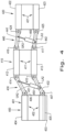
- the header 400 can include a main section 401 including a main frame 402 carrying one or more cutting elements 403, such as a cutter bar, a first segment section 410 pivotably coupled to the main section 401 and including a first segment frame 411, and can also include a second segment section 420 pivotably coupled to the first segment section 410 and including a second segment frame 421.
- the main frame 402 of the main section 401 can include an upper main bar 404 and a lower main bar 405, with the main bars 404, 405 of the main frame 402 being connected to, for example, the chassis 102 of the agricultural vehicle 100.
- first segment frame 411 can include a first segment upper bar 412 and a first segment lower bar 413 and the second segment frame 421 can include a second segment upper bar 422 and a second segment lower bar 423.
- first segment frame 411 and/or the second segment frame 421 are formed to be substantially rigid, i.e., resistant to easily bending, by forming the frames 411, 412 out of, for example, a relatively rigid metal such as steel.
- a linkage 430 pivotably couples the first segment section 410 to the main section 401 and includes an upper bar 431 and a lower bar 432 which are both coupled to the main frame 402 and the first segment frame 411.
- the upper bar 431 can pivotably couple to the upper main bar 404 at an upper main pivot 406 and the first segment upper bar 412 at a first segment upper pivot 414 and the lower bar 432 can pivotably couple to the lower main bar 405 at a lower main pivot 407 and the first segment lower bar 413 at a first segment lower pivot 415.
- a second linkage 440 can pivotably couple the first segment section 410 to the second segment section 430 and include a second upper bar 441 and a second lower bar 442.
- the second upper bar 441 can pivotably couple to the first segment upper bar 412 at another first segment upper pivot 416 and the second segment upper bar 422 at a second segment upper pivot 424 and the second lower bar 442 can pivotably couple to the first segment lower bar 413 at another first segment lower pivot 417 and the second lower bar 442 at a second segment lower pivot 425.
- additional segment sections can be added, if desired, and have similar constructions to the first and second segment sections 410, 420 described herein.
- an actuator 450 is coupled to the upper bar 431, the lower bar 432, and/or the first segment section 410.
- the actuator 450 can couple the upper bar 431 to the lower bar 432, as shown, or, alternatively, the actuator 450 may connect to other parts of the header 400 such as the main section 401 or the first segment section 411.
- the actuator 450 can be part of a gauge wheel assembly (not shown) which supports the weight of the first segment section 410 and allows the first segment section 410 to follow the ground.
- the actuator 450 can be, for example, a selectively activated cylinder which can cause linear up and down movement of the upper main bar 403 and lower main bar 404 as well as the first segment upper bar 412 and first segment lower bar 413. Additionally, the actuator 450 can be selectively activated to control pivoting behavior of the first segment section 410 relative to the main section 401.
- a second actuator 460 can couple to the second upper bar 441, the second lower bar 442, and/or the second segment section 430; the second actuator 460 can couple the second upper bar 441 to the second lower bar 442, as shown, to other parts of the header 400, or be a part of a gauge wheel assembly (not shown), similar to the previously described actuator 450.
- ground following of the cutter bar 403 can be improved due to the segment sections 410, 420 coupled to the main section 401 being independently pivotable, relative to the main section 401 and each other, and able to "float" on the ground as the vehicle 100 travels across a field.
- the actuators 450, 460 therefore, can act to help control the float behavior of the segment section(s) 410, 420 to assist the header 400 in following the ground by pushing or pulling on a respectively connected element and causing a corresponding change in the following behavior of the segment section(s) 410, 420.
- the upper bar 431 of the first linkage 430 can define an upper bar axis UA2 and the lower bar 432 of the first linkage 430 can define a lower bar axis LA2 which is parallel to the upper bar axis UA2.
- the second upper bar 441 of the second linkage 440 can define a second upper bar axis UA3 and the second lower bar 442 of the second linkage 440 can define a second lower bar axis LA3 which is parallel to the second upper bar axis UA3.
- the upper bar axis UA2 and lower bar axis LA2 are non-parallel to the second upper bar axis UA3 and second lower bar axis LA3, which can be a result of the header 400 traveling across uneven terrain or an intentional relative angling.
Landscapes
- Life Sciences & Earth Sciences (AREA)
- Environmental Sciences (AREA)
- Engineering & Computer Science (AREA)
- Mechanical Engineering (AREA)
- Soil Sciences (AREA)
- Agricultural Machines (AREA)
- Harvester Elements (AREA)
- Harvesting Machines For Specific Crops (AREA)
Claims (13)
- Landwirtschaftlicher Vorsatz (110; 400), umfassend:einen Hauptabschnitt (111; 401), der einen Hauptrahmen (112; 402) einschließt, der ein Schneidelement (113; 403) trägt;mindestens einen Flügelabschnitt (120, 130; 410, 420), der mit dem Hauptabschnitt (111; 401) schwenkbar gekoppelt ist und einen Flügelrahmen (121, 131; 411, 421) einschließt, wobei der Flügelrahmen (121, 131; 411, 421) das Schneidelement (113; 403) so trägt, dass eine schwenkbare Bewegung des mindestens einen Flügelabschnitts (120; 410, 420) eine entsprechende Biegung des mindestens einen Schneidelements (113; 403) verursacht; undeine Verbindung (200; 430), die den mindestens einen Flügelabschnitt (120; 410, 420) mit dem Hauptabschnitt (111; 401) schwenkbar koppelt, wobei die Verbindung (200; 430) eine obere Stange (201; 431) und eine untere Stange (202; 432) einschließt, die beide mit dem Hauptrahmen (112; 402) und dem Flügelrahmen (121, 131; 411, 421) gekoppelt sind, gekennzeichnet durcheinen Aktuator (450), der mit mindestens einem von der oberen Stange (431), der unteren Stange (432) und dem mindestens einen Flügelabschnitt (410) gekoppelt ist.
- Landwirtschaftlicher Vorsatz (110) nach Anspruch 1, wobei die obere Stange (201) eine obere Stangenachse (UA1) definiert und die untere Stange (202) eine untere Stangenachse (LA1) definiert, die nicht parallel zu der oberen Stangenachse (UA1) ist.
- Landwirtschaftlicher Vorsatz (110) nach Anspruch 2, wobei der mindestens eine Flügelabschnitt (120) eine Flügellängsachse (WLA) definiert, wobei mindestens eine der oberen Stangenachse (UA1) und der unteren Stangenachse (LA1) nicht parallel zu der Flügellängsachse (WLA) ist.
- Landwirtschaftlicher Vorsatz (110) nach Anspruch 3, wobei die obere Stangenachse (UA1) und die untere Stangenachse (LA1) beide nicht parallel zu der Flügellängsachse (WLA) sind.
- Landwirtschaftlicher Vorsatz (110) nach einem der vorstehenden Ansprüche, wobei der Hauptabschnitt (111) einen oberen Hauptdrehzapfen (216) und einen unteren Hauptdrehzapfen (217) einschließt und der mindestens eine Flügelabschnitt (120) einen oberen Flügeldrehzapfen (223) und einen unteren Flügeldrehzapfen (224) einschließt, wobei die obere Stange (201) mit dem oberen Hauptdrehzapfen (216) und dem oberen Flügeldrehzapfen (223) gekoppelt ist und die untere Stange (202) mit dem unteren Hauptdrehzapfen (217) und dem unteren Flügeldrehzapfen (224) gekoppelt ist.
- Landwirtschaftlicher Vorsatz (110) nach Anspruch 5, wobei die obere Stange (201) eine obere Stangenlänge (UL) definiert und die untere Stange (202) eine untere Stangenlänge (LL) definiert, die gleich der oberen Stangenlänge (UL) ist.
- Landwirtschaftlicher Vorsatz (110) nach einem der vorstehenden Ansprüche, wobei die Verbindung (200) konfiguriert ist, um die obere Stangenachse (UA1) und die untere Stangenachse (LA1) in einer nicht parallelen Beziehung ungeachtet einer Ausrichtung des mindestens einen Flügelabschnitts (120) relativ zu dem Hauptabschnitt (111) zu halten.
- Landwirtschaftlicher Vorsatz (400) nach Anspruch 1, wobei der Flügelrahmen (411, 421) im Wesentlichen starr ist.
- Landwirtschaftlicher Vorsatz (400) nach Anspruch 1, wobei der Aktuator (450) die obere Stange (431) mit der unteren Stange (432) koppelt.
- Landwirtschaftlicher Vorsatz (400) nach einem der vorstehenden Ansprüche, wobei der mindestens eine Flügelabschnitt (410, 420) einen ersten Segmentabschnitt (410), der mit dem Hauptabschnitt (401) schwenkbar gekoppelt ist, und einen zweiten Segmentabschnitt (420), der mit dem ersten Segmentabschnitt (410) schwenkbar gekoppelt ist, umfasst.
- Landwirtschaftlicher Vorsatz (400) nach Anspruch 10, ferner umfassend eine zweite Verbindung (440), die den zweiten Segmentabschnitt (420) mit dem ersten Segmentabschnitt (410) schwenkbar koppelt, wobei die zweite Verbindung (440) eine zweite obere Stange (441) und eine zweite untere Stange (442) einschließt, die beide mit dem zweiten Segmentabschnitt (420) und dem ersten Segmentabschnitt (410) gekoppelt sind.
- Landwirtschaftlicher Vorsatz (400) nach Anspruch 11, ferner umfassend einen zweiten Aktuator (460), der mit mindestens einem von der zweiten oberen Stange (441), der zweiten unteren Stange (442) und dem zweiten Segmentabschnitt (420) gekoppelt ist.
- Landwirtschaftlicher Vorsatz (400) nach Anspruch 12, wobei der zweite Aktuator (460) die zweite obere Stange (441) mit der zweiten unteren Stange (442) koppelt.
Applications Claiming Priority (1)
| Application Number | Priority Date | Filing Date | Title |
|---|---|---|---|
| US15/681,732 US10433483B2 (en) | 2017-08-21 | 2017-08-21 | Agricultural header with one or more movable wing sections |
Publications (3)
| Publication Number | Publication Date |
|---|---|
| EP3446558A1 EP3446558A1 (de) | 2019-02-27 |
| EP3446558B1 EP3446558B1 (de) | 2020-04-08 |
| EP3446558B2 true EP3446558B2 (de) | 2023-03-29 |
Family
ID=63103832
Family Applications (1)
| Application Number | Title | Priority Date | Filing Date |
|---|---|---|---|
| EP18186329.1A Active EP3446558B2 (de) | 2017-08-21 | 2018-07-30 | Landwirtschaftlicher erntevorsatz mit einem oder mehreren beweglichen flügelabschnitten |
Country Status (2)
| Country | Link |
|---|---|
| US (5) | US10433483B2 (de) |
| EP (1) | EP3446558B2 (de) |
Families Citing this family (22)
| Publication number | Priority date | Publication date | Assignee | Title |
|---|---|---|---|---|
| US10617059B2 (en) * | 2016-06-21 | 2020-04-14 | Macdon Industries Ltd. | Crop machine with an electronically controlled hydraulic cylinder flotation system |
| US10426088B2 (en) | 2017-10-11 | 2019-10-01 | Deere & Company | Center feed assembly for a draper |
| US10537063B2 (en) | 2017-10-11 | 2020-01-21 | Deere & Company | Folding agricultural head |
| US10433486B2 (en) * | 2017-10-16 | 2019-10-08 | Deere & Company | System and method for wing float on a combine draper header |
| US10568266B2 (en) * | 2017-10-17 | 2020-02-25 | Deere & Company | Self-contained combine draper wing leveler |
| WO2019136281A1 (en) * | 2018-01-04 | 2019-07-11 | Cnh Industrial America Llc | Agricultural harvester with header having conformable portions |
| US10813289B2 (en) * | 2018-06-05 | 2020-10-27 | Deere & Company | Single top beam folding corn head mainframe |
| US11297765B2 (en) * | 2018-07-02 | 2022-04-12 | Deere & Company | Suspension compliance to reduce frame loading |
| WO2020101872A1 (en) * | 2018-11-16 | 2020-05-22 | Cnh Industrial America Llc | Header with trapezoidal profile |
| AR118293A1 (es) * | 2019-03-11 | 2021-09-22 | Cnh Ind America Llc | Control de altura de cabezal para un cabezal cosechador |
| US11219162B2 (en) * | 2019-04-23 | 2022-01-11 | Deere & Company | Controlled header lowering on an agricultural harvester |
| US11064654B2 (en) * | 2019-05-01 | 2021-07-20 | Deere & Company | Float adjustment |
| US11019770B2 (en) * | 2019-05-28 | 2021-06-01 | Deere & Company | Harvester wing leveling configuration |
| US11627701B2 (en) | 2019-10-31 | 2023-04-18 | Deere & Company | Agricultural header with flexible joint |
| US11464167B2 (en) * | 2019-11-05 | 2022-10-11 | Cnh Industrial America Llc | Road travel system for an agricultural vehicle |
| US11533847B2 (en) | 2019-12-23 | 2022-12-27 | Cnh Industrial America Llc | Control of a header of a harvester during a non-harvesting mode |
| US11785890B2 (en) * | 2020-06-17 | 2023-10-17 | Deere & Company | Corn head adjustment system with integrated actuation |
| DE102020124362A1 (de) | 2020-06-25 | 2021-12-30 | Pöttinger Landtechnik Gmbh | Landwirtschaftliche Maschine |
| EP3928612A1 (de) * | 2020-06-25 | 2021-12-29 | Pöttinger Landtechnik GmbH | Landwirtschaftliche maschine |
| US12108704B2 (en) * | 2021-05-19 | 2024-10-08 | Deere & Company | Agricultural header reel position control based on header wing position |
| US20240373776A1 (en) * | 2021-08-06 | 2024-11-14 | Cnh Industrial America Llc | Position control of a segmented agricultural work assembly |
| US12507628B2 (en) | 2022-10-13 | 2025-12-30 | Deere & Company | Agricultural system with deck plate positioning control |
Citations (3)
| Publication number | Priority date | Publication date | Assignee | Title |
|---|---|---|---|---|
| EP3395155A1 (de) † | 2017-04-28 | 2018-10-31 | Deere & Company | Mehrteiliges schneidwerk mit versetzter schwenkachse |
| EP3469876A1 (de) † | 2017-10-16 | 2019-04-17 | Deere & Company | System und verfahren zum gleiten einer horde an einem draper-schneidwerk eines mähdreschers |
| EP3473076A1 (de) † | 2017-10-17 | 2019-04-24 | Deere & Company | Selbstständiger mähdrescherschneidwerkflügelnivellierer |
Family Cites Families (55)
| Publication number | Priority date | Publication date | Assignee | Title |
|---|---|---|---|---|
| DK100018A (de) * | 1961-07-19 | |||
| NL6414183A (de) * | 1964-12-05 | 1966-06-06 | ||
| NL6903371A (de) * | 1969-03-05 | 1970-09-08 | ||
| USRE31209E (en) * | 1976-01-26 | 1983-04-19 | Agricultural implement with foldable tool supporting frame | |
| US4030551A (en) | 1976-04-12 | 1977-06-21 | International Harvester Company | Folding flex toolbar |
| US4126189A (en) * | 1977-01-21 | 1978-11-21 | Graber Industries, Inc. | Folding tool carrier |
| US4409780A (en) | 1982-03-11 | 1983-10-18 | Kansas State University Research Foundation | Folding header assembly |
| DE3307633C2 (de) | 1983-03-04 | 1994-08-25 | Claas Ohg | Selbstfahrender Mähdrescher |
| US4487004A (en) | 1983-06-03 | 1984-12-11 | Kejr Melvin P | Combine harvester apparatus |
| US4588128A (en) * | 1985-02-25 | 1986-05-13 | The Broyhill Company | Folding boom for agricultural sprayers |
| US4660651A (en) | 1985-06-28 | 1987-04-28 | Krause Plow Corporation | Highly flexible, foldable drill for uniform depth seed deposit |
| US4903470A (en) | 1987-09-14 | 1990-02-27 | Claas Ohg | Self-propelling harvester thresher with two-part cutting mechanism |
| DE3906456A1 (de) | 1989-03-01 | 1990-09-06 | Claas Ohg | Selbstfahrender maehdrescher mit zweigeteiltem schneidwerk |
| US5577563A (en) * | 1995-07-27 | 1996-11-26 | Holen; Kurt | Stack-folding toolbar with floating wings |
| US5724798A (en) * | 1996-07-08 | 1998-03-10 | Byron Enterprises Inc. | Latch for a folding corn head |
| US5673543A (en) * | 1996-01-04 | 1997-10-07 | Byron Enterprises, Inc | Foldable corn head with unobstructed auger |
| IT1285240B1 (it) | 1996-02-16 | 1998-06-03 | Capello R & F Flli | Testata per cereali applicabile su mietitrebbia |
| DE19635992A1 (de) * | 1996-09-05 | 1998-03-12 | Same Spa | Selbstfahrende landwirtschaftliche Erntemaschine |
| DE19725530A1 (de) | 1997-06-17 | 1998-12-24 | Claas Saulgau Gmbh | Schwenkrahmen eines Erntevorsatzgerätes an landwirtschaftlichen Arbeitsmaschinen zum Aufnehmen und Weiterleiten von Erntegut |
| US6003615A (en) * | 1998-08-19 | 1999-12-21 | Moore; Paul O. | Stacking tool bar including a wing flex structure |
| IT1315102B1 (it) | 2000-06-30 | 2003-02-03 | Cressoni Spa Flli | Apparecchiatura barra di taglio per macchine agricole di raccolta |
| IT1315101B1 (it) | 2000-06-30 | 2003-02-03 | Cressoni Spa Flli | Apparecchiatura barra di taglio per macchine agricole di raccolta |
| DE10039097A1 (de) * | 2000-08-07 | 2002-02-21 | Claas Saulgau Gmbh | Verfahren und Vorrichtung zum Schwenken der Abteiler von mehrteiligen landwirtschaftlichen Erntemaschinen |
| CA2387898C (en) | 2001-06-18 | 2005-01-11 | Macdon Industries Ltd. | Multi-section header with flexible crop cutting knife |
| HUP0300512A2 (hu) * | 2002-03-28 | 2004-09-28 | Claas Saulgau Gmbh | Kaszáló berendezés |
| DE10221983A1 (de) * | 2002-05-17 | 2003-11-27 | Kemper Gmbh Maschf | Erntevorsatz |
| DE10250337A1 (de) * | 2002-10-29 | 2004-05-19 | Maschinenfabrik Kemper Gmbh & Co. Kg | Verstelleinrichtung für einen Erntevorsatz |
| DE102005004004A1 (de) * | 2005-01-27 | 2006-08-17 | Maschinenfabrik Bernard Krone Gmbh | Selbstfahrende landwirtschaftliche Erntemaschine |
| DE102005016350A1 (de) * | 2005-04-09 | 2006-10-12 | Maschinenfabrik Kemper Gmbh & Co. Kg | Erntevorsatz für landwirtschaftliche Erntemaschinen |
| FR2885483B1 (fr) * | 2005-05-10 | 2007-06-15 | Kuhn Sa Sa | Faucheuse avec des ensembles de fauche repliables |
| US7918076B2 (en) * | 2006-09-25 | 2011-04-05 | Macdon Industries Ltd. | Device for maintaining wing balance on a multi-section header |
| US7971417B2 (en) * | 2006-12-05 | 2011-07-05 | Deere & Company | Elective down pressure system for cutting units of grass mowing machine |
| US7614206B2 (en) * | 2007-06-04 | 2009-11-10 | Claas Selbstfahrende Erntemaschinen Gmbh | Winged header apparatus and method for a combine |
| DE102007058312A1 (de) | 2007-12-04 | 2009-06-10 | Maschinenfabrik Kemper Gmbh & Co. Kg | Erntevorsatz für landwirtschaftliche Erntemaschinen zum Aufnehmen und Weiterfördern von Halmfrüchten |
| US8635842B2 (en) * | 2009-08-05 | 2014-01-28 | Kevin Markt | Flexible row crop header for an agricultural harvester |
| US8087224B1 (en) * | 2010-09-16 | 2012-01-03 | Deere & Company | Flexible draper platform with pivot geometry |
| ITPD20120242A1 (it) | 2012-08-06 | 2014-02-07 | Cressoni S P A Flli | Testata ripiegabile per macchina spannocchiatrice e/o mietitrebbia e metodo di ripiegatura di una testata di macchina spannocchiatrice e/o mietitrebbia |
| US9198353B2 (en) * | 2012-09-20 | 2015-12-01 | Deere & Company | Hinged row crop harvesting head |
| DE102013001651B4 (de) * | 2013-01-31 | 2024-12-19 | Claas Saulgau Gmbh | Schutzvorrichtung eines Mäh- und Einzugswerks einer Erntemaschine und Erntemaschine mit einer solchen Schutzvorrichtung |
| US8893088B2 (en) * | 2013-04-02 | 2014-11-18 | Apple Inc. | Dynamic program evaluation for system adaptation |
| DE102014009161B4 (de) | 2014-06-25 | 2023-01-26 | Carl Geringhoff Gmbh & Co. Kg | Schneidwerk mit Mittelteil und dazu verstellbaren Seitenteilen |
| CA2913937C (en) * | 2014-12-29 | 2017-10-10 | BN Equipment Design Ltd. | Gauge wheels for a multi-section agricultural header |
| BR102016005189B1 (pt) | 2015-03-13 | 2020-11-17 | Cnh Industrial Belgium Nv | Colheitadeira agricola |
| US9955624B2 (en) * | 2015-12-22 | 2018-05-01 | Sammut Agricultural Machinery Pty Ltd. | Wide area turf mower |
| US10070575B2 (en) | 2016-08-05 | 2018-09-11 | Cnh Industrial America Llc | Agricultural machine with folding header |
| US10405474B2 (en) * | 2017-04-30 | 2019-09-10 | Deere & Company | Multilink connection between harvesting head adapter frame and mainframe |
| US10517217B2 (en) * | 2017-07-20 | 2019-12-31 | Deere & Company | Cotton picker unit lift structure |
| US10517215B2 (en) * | 2017-10-12 | 2019-12-31 | Deere & Company | Roll center for attachment frame control arms |
| US10820510B2 (en) * | 2018-06-15 | 2020-11-03 | Deere & Company | Cutterbar angle change with four bar linkage |
| US10945370B2 (en) * | 2018-08-16 | 2021-03-16 | Deere & Company | System and method for ground following of a combine header with flexible cutter bar |
| US11032970B2 (en) * | 2018-10-30 | 2021-06-15 | Deere & Company | Varying a hydraulic cylinder mechanical advantage to obtain smoother float pressure |
| US11191212B2 (en) * | 2019-04-23 | 2021-12-07 | Deere & Company | Controlled float on an agricultural harvester for header leveling |
| US11064654B2 (en) * | 2019-05-01 | 2021-07-20 | Deere & Company | Float adjustment |
| US11058056B2 (en) * | 2019-05-06 | 2021-07-13 | Deere & Company | Gang arm gauge wheel height control for crop harvesting device |
| US11375654B2 (en) * | 2019-10-08 | 2022-07-05 | Deere & Company | Method and apparatus for adjusting a harvesting header float system based on machine pitch or terrain and system thereof |
-
2017
- 2017-08-21 US US15/681,732 patent/US10433483B2/en active Active
-
2018
- 2018-07-30 EP EP18186329.1A patent/EP3446558B2/de active Active
-
2019
- 2019-08-07 US US16/534,241 patent/US11224165B2/en active Active
-
2021
- 2021-09-24 US US17/484,056 patent/US20220007580A1/en not_active Abandoned
-
2022
- 2022-10-24 US US17/972,239 patent/US11930739B2/en active Active
-
2023
- 2023-12-15 US US18/541,113 patent/US20240107945A1/en not_active Abandoned
Patent Citations (3)
| Publication number | Priority date | Publication date | Assignee | Title |
|---|---|---|---|---|
| EP3395155A1 (de) † | 2017-04-28 | 2018-10-31 | Deere & Company | Mehrteiliges schneidwerk mit versetzter schwenkachse |
| EP3469876A1 (de) † | 2017-10-16 | 2019-04-17 | Deere & Company | System und verfahren zum gleiten einer horde an einem draper-schneidwerk eines mähdreschers |
| EP3473076A1 (de) † | 2017-10-17 | 2019-04-24 | Deere & Company | Selbstständiger mähdrescherschneidwerkflügelnivellierer |
Also Published As
| Publication number | Publication date |
|---|---|
| US20240107945A1 (en) | 2024-04-04 |
| EP3446558A1 (de) | 2019-02-27 |
| US20190357439A1 (en) | 2019-11-28 |
| EP3446558B1 (de) | 2020-04-08 |
| US11930739B2 (en) | 2024-03-19 |
| US10433483B2 (en) | 2019-10-08 |
| US20230053193A1 (en) | 2023-02-16 |
| US20190053429A1 (en) | 2019-02-21 |
| BR102018017123A2 (pt) | 2019-03-19 |
| US20220007580A1 (en) | 2022-01-13 |
| US11224165B2 (en) | 2022-01-18 |
Similar Documents
| Publication | Publication Date | Title |
|---|---|---|
| US11930739B2 (en) | Agricultural header with one or more movable wing sections | |
| USRE49178E1 (en) | Agricultural machine with folding header | |
| EP3469878B1 (de) | Rollzentrum für erntevorsatzrahmensteuerungsarmen | |
| EP3681265B1 (de) | Landwirtschaftlicher erntevorsatz mit konstantem verhältnis zwischen haspel und schneidwerk | |
| EP3599816B1 (de) | Selbstlagernde schneidwerkschnecke | |
| US20190104682A1 (en) | Center feed assembly for a draper | |
| US12245552B2 (en) | Adjustable reel arm | |
| CA3072370C (en) | Agricultural header with constant reel to cutter relationship | |
| US11375664B2 (en) | Agricultural header with linearly displaceable flex arms | |
| EP3659427B1 (de) | Seitlich versetzte transporträder an erntevorsatz | |
| US20240341222A1 (en) | Agricultural header with a pivot sensor linkage | |
| BR102018017123B1 (pt) | Plataforma agrícola | |
| BR112020004972B1 (pt) | Plataforma para um veículo agrícola e veículo agrícola |
Legal Events
| Date | Code | Title | Description |
|---|---|---|---|
| PUAI | Public reference made under article 153(3) epc to a published international application that has entered the european phase |
Free format text: ORIGINAL CODE: 0009012 |
|
| STAA | Information on the status of an ep patent application or granted ep patent |
Free format text: STATUS: THE APPLICATION HAS BEEN PUBLISHED |
|
| AK | Designated contracting states |
Kind code of ref document: A1 Designated state(s): AL AT BE BG CH CY CZ DE DK EE ES FI FR GB GR HR HU IE IS IT LI LT LU LV MC MK MT NL NO PL PT RO RS SE SI SK SM TR |
|
| AX | Request for extension of the european patent |
Extension state: BA ME |
|
| STAA | Information on the status of an ep patent application or granted ep patent |
Free format text: STATUS: REQUEST FOR EXAMINATION WAS MADE |
|
| 17P | Request for examination filed |
Effective date: 20190827 |
|
| RBV | Designated contracting states (corrected) |
Designated state(s): AL AT BE BG CH CY CZ DE DK EE ES FI FR GB GR HR HU IE IS IT LI LT LU LV MC MK MT NL NO PL PT RO RS SE SI SK SM TR |
|
| RIC1 | Information provided on ipc code assigned before grant |
Ipc: A01D 41/14 20060101AFI20190925BHEP |
|
| GRAP | Despatch of communication of intention to grant a patent |
Free format text: ORIGINAL CODE: EPIDOSNIGR1 |
|
| STAA | Information on the status of an ep patent application or granted ep patent |
Free format text: STATUS: GRANT OF PATENT IS INTENDED |
|
| INTG | Intention to grant announced |
Effective date: 20191104 |
|
| GRAS | Grant fee paid |
Free format text: ORIGINAL CODE: EPIDOSNIGR3 |
|
| GRAA | (expected) grant |
Free format text: ORIGINAL CODE: 0009210 |
|
| STAA | Information on the status of an ep patent application or granted ep patent |
Free format text: STATUS: THE PATENT HAS BEEN GRANTED |
|
| AK | Designated contracting states |
Kind code of ref document: B1 Designated state(s): AL AT BE BG CH CY CZ DE DK EE ES FI FR GB GR HR HU IE IS IT LI LT LU LV MC MK MT NL NO PL PT RO RS SE SI SK SM TR |
|
| REG | Reference to a national code |
Ref country code: CH Ref legal event code: EP Ref country code: AT Ref legal event code: REF Ref document number: 1253107 Country of ref document: AT Kind code of ref document: T Effective date: 20200415 |
|
| REG | Reference to a national code |
Ref country code: DE Ref legal event code: R096 Ref document number: 602018003592 Country of ref document: DE |
|
| REG | Reference to a national code |
Ref country code: IE Ref legal event code: FG4D |
|
| REG | Reference to a national code |
Ref country code: NL Ref legal event code: MP Effective date: 20200408 |
|
| REG | Reference to a national code |
Ref country code: LT Ref legal event code: MG4D |
|
| PG25 | Lapsed in a contracting state [announced via postgrant information from national office to epo] |
Ref country code: LT Free format text: LAPSE BECAUSE OF FAILURE TO SUBMIT A TRANSLATION OF THE DESCRIPTION OR TO PAY THE FEE WITHIN THE PRESCRIBED TIME-LIMIT Effective date: 20200408 Ref country code: GR Free format text: LAPSE BECAUSE OF FAILURE TO SUBMIT A TRANSLATION OF THE DESCRIPTION OR TO PAY THE FEE WITHIN THE PRESCRIBED TIME-LIMIT Effective date: 20200709 Ref country code: PT Free format text: LAPSE BECAUSE OF FAILURE TO SUBMIT A TRANSLATION OF THE DESCRIPTION OR TO PAY THE FEE WITHIN THE PRESCRIBED TIME-LIMIT Effective date: 20200817 Ref country code: NL Free format text: LAPSE BECAUSE OF FAILURE TO SUBMIT A TRANSLATION OF THE DESCRIPTION OR TO PAY THE FEE WITHIN THE PRESCRIBED TIME-LIMIT Effective date: 20200408 Ref country code: FI Free format text: LAPSE BECAUSE OF FAILURE TO SUBMIT A TRANSLATION OF THE DESCRIPTION OR TO PAY THE FEE WITHIN THE PRESCRIBED TIME-LIMIT Effective date: 20200408 Ref country code: NO Free format text: LAPSE BECAUSE OF FAILURE TO SUBMIT A TRANSLATION OF THE DESCRIPTION OR TO PAY THE FEE WITHIN THE PRESCRIBED TIME-LIMIT Effective date: 20200708 Ref country code: IS Free format text: LAPSE BECAUSE OF FAILURE TO SUBMIT A TRANSLATION OF THE DESCRIPTION OR TO PAY THE FEE WITHIN THE PRESCRIBED TIME-LIMIT Effective date: 20200808 Ref country code: SE Free format text: LAPSE BECAUSE OF FAILURE TO SUBMIT A TRANSLATION OF THE DESCRIPTION OR TO PAY THE FEE WITHIN THE PRESCRIBED TIME-LIMIT Effective date: 20200408 |
|
| REG | Reference to a national code |
Ref country code: AT Ref legal event code: MK05 Ref document number: 1253107 Country of ref document: AT Kind code of ref document: T Effective date: 20200408 |
|
| PG25 | Lapsed in a contracting state [announced via postgrant information from national office to epo] |
Ref country code: RS Free format text: LAPSE BECAUSE OF FAILURE TO SUBMIT A TRANSLATION OF THE DESCRIPTION OR TO PAY THE FEE WITHIN THE PRESCRIBED TIME-LIMIT Effective date: 20200408 Ref country code: HR Free format text: LAPSE BECAUSE OF FAILURE TO SUBMIT A TRANSLATION OF THE DESCRIPTION OR TO PAY THE FEE WITHIN THE PRESCRIBED TIME-LIMIT Effective date: 20200408 Ref country code: BG Free format text: LAPSE BECAUSE OF FAILURE TO SUBMIT A TRANSLATION OF THE DESCRIPTION OR TO PAY THE FEE WITHIN THE PRESCRIBED TIME-LIMIT Effective date: 20200708 Ref country code: LV Free format text: LAPSE BECAUSE OF FAILURE TO SUBMIT A TRANSLATION OF THE DESCRIPTION OR TO PAY THE FEE WITHIN THE PRESCRIBED TIME-LIMIT Effective date: 20200408 |
|
| REG | Reference to a national code |
Ref country code: DE Ref legal event code: R026 Ref document number: 602018003592 Country of ref document: DE |
|
| PLBI | Opposition filed |
Free format text: ORIGINAL CODE: 0009260 |
|
| PG25 | Lapsed in a contracting state [announced via postgrant information from national office to epo] |
Ref country code: AL Free format text: LAPSE BECAUSE OF FAILURE TO SUBMIT A TRANSLATION OF THE DESCRIPTION OR TO PAY THE FEE WITHIN THE PRESCRIBED TIME-LIMIT Effective date: 20200408 |
|
| 26 | Opposition filed |
Opponent name: DEERE & COMPANY/JOHN DEERE GMBH & CO. KG Effective date: 20201207 |
|
| PLAX | Notice of opposition and request to file observation + time limit sent |
Free format text: ORIGINAL CODE: EPIDOSNOBS2 |
|
| PG25 | Lapsed in a contracting state [announced via postgrant information from national office to epo] |
Ref country code: RO Free format text: LAPSE BECAUSE OF FAILURE TO SUBMIT A TRANSLATION OF THE DESCRIPTION OR TO PAY THE FEE WITHIN THE PRESCRIBED TIME-LIMIT Effective date: 20200408 Ref country code: CZ Free format text: LAPSE BECAUSE OF FAILURE TO SUBMIT A TRANSLATION OF THE DESCRIPTION OR TO PAY THE FEE WITHIN THE PRESCRIBED TIME-LIMIT Effective date: 20200408 Ref country code: ES Free format text: LAPSE BECAUSE OF FAILURE TO SUBMIT A TRANSLATION OF THE DESCRIPTION OR TO PAY THE FEE WITHIN THE PRESCRIBED TIME-LIMIT Effective date: 20200408 Ref country code: EE Free format text: LAPSE BECAUSE OF FAILURE TO SUBMIT A TRANSLATION OF THE DESCRIPTION OR TO PAY THE FEE WITHIN THE PRESCRIBED TIME-LIMIT Effective date: 20200408 Ref country code: SM Free format text: LAPSE BECAUSE OF FAILURE TO SUBMIT A TRANSLATION OF THE DESCRIPTION OR TO PAY THE FEE WITHIN THE PRESCRIBED TIME-LIMIT Effective date: 20200408 Ref country code: AT Free format text: LAPSE BECAUSE OF FAILURE TO SUBMIT A TRANSLATION OF THE DESCRIPTION OR TO PAY THE FEE WITHIN THE PRESCRIBED TIME-LIMIT Effective date: 20200408 Ref country code: DK Free format text: LAPSE BECAUSE OF FAILURE TO SUBMIT A TRANSLATION OF THE DESCRIPTION OR TO PAY THE FEE WITHIN THE PRESCRIBED TIME-LIMIT Effective date: 20200408 |
|
| PG25 | Lapsed in a contracting state [announced via postgrant information from national office to epo] |
Ref country code: SK Free format text: LAPSE BECAUSE OF FAILURE TO SUBMIT A TRANSLATION OF THE DESCRIPTION OR TO PAY THE FEE WITHIN THE PRESCRIBED TIME-LIMIT Effective date: 20200408 Ref country code: PL Free format text: LAPSE BECAUSE OF FAILURE TO SUBMIT A TRANSLATION OF THE DESCRIPTION OR TO PAY THE FEE WITHIN THE PRESCRIBED TIME-LIMIT Effective date: 20200408 Ref country code: MC Free format text: LAPSE BECAUSE OF FAILURE TO SUBMIT A TRANSLATION OF THE DESCRIPTION OR TO PAY THE FEE WITHIN THE PRESCRIBED TIME-LIMIT Effective date: 20200408 |
|
| REG | Reference to a national code |
Ref country code: BE Ref legal event code: MM Effective date: 20200731 |
|
| PG25 | Lapsed in a contracting state [announced via postgrant information from national office to epo] |
Ref country code: LU Free format text: LAPSE BECAUSE OF NON-PAYMENT OF DUE FEES Effective date: 20200730 |
|
| PG25 | Lapsed in a contracting state [announced via postgrant information from national office to epo] |
Ref country code: SI Free format text: LAPSE BECAUSE OF FAILURE TO SUBMIT A TRANSLATION OF THE DESCRIPTION OR TO PAY THE FEE WITHIN THE PRESCRIBED TIME-LIMIT Effective date: 20200408 Ref country code: BE Free format text: LAPSE BECAUSE OF NON-PAYMENT OF DUE FEES Effective date: 20200731 |
|
| PLBB | Reply of patent proprietor to notice(s) of opposition received |
Free format text: ORIGINAL CODE: EPIDOSNOBS3 |
|
| PG25 | Lapsed in a contracting state [announced via postgrant information from national office to epo] |
Ref country code: IE Free format text: LAPSE BECAUSE OF NON-PAYMENT OF DUE FEES Effective date: 20200730 |
|
| REG | Reference to a national code |
Ref country code: CH Ref legal event code: PL |
|
| PG25 | Lapsed in a contracting state [announced via postgrant information from national office to epo] |
Ref country code: LI Free format text: LAPSE BECAUSE OF NON-PAYMENT OF DUE FEES Effective date: 20210731 Ref country code: CH Free format text: LAPSE BECAUSE OF NON-PAYMENT OF DUE FEES Effective date: 20210731 |
|
| PG25 | Lapsed in a contracting state [announced via postgrant information from national office to epo] |
Ref country code: TR Free format text: LAPSE BECAUSE OF FAILURE TO SUBMIT A TRANSLATION OF THE DESCRIPTION OR TO PAY THE FEE WITHIN THE PRESCRIBED TIME-LIMIT Effective date: 20200408 Ref country code: MT Free format text: LAPSE BECAUSE OF FAILURE TO SUBMIT A TRANSLATION OF THE DESCRIPTION OR TO PAY THE FEE WITHIN THE PRESCRIBED TIME-LIMIT Effective date: 20200408 Ref country code: CY Free format text: LAPSE BECAUSE OF FAILURE TO SUBMIT A TRANSLATION OF THE DESCRIPTION OR TO PAY THE FEE WITHIN THE PRESCRIBED TIME-LIMIT Effective date: 20200408 |
|
| PG25 | Lapsed in a contracting state [announced via postgrant information from national office to epo] |
Ref country code: MK Free format text: LAPSE BECAUSE OF FAILURE TO SUBMIT A TRANSLATION OF THE DESCRIPTION OR TO PAY THE FEE WITHIN THE PRESCRIBED TIME-LIMIT Effective date: 20200408 |
|
| PUAH | Patent maintained in amended form |
Free format text: ORIGINAL CODE: 0009272 |
|
| STAA | Information on the status of an ep patent application or granted ep patent |
Free format text: STATUS: PATENT MAINTAINED AS AMENDED |
|
| 27A | Patent maintained in amended form |
Effective date: 20230329 |
|
| AK | Designated contracting states |
Kind code of ref document: B2 Designated state(s): AL AT BE BG CH CY CZ DE DK EE ES FI FR GB GR HR HU IE IS IT LI LT LU LV MC MK MT NL NO PL PT RO RS SE SI SK SM TR |
|
| REG | Reference to a national code |
Ref country code: DE Ref legal event code: R102 Ref document number: 602018003592 Country of ref document: DE |
|
| PGFP | Annual fee paid to national office [announced via postgrant information from national office to epo] |
Ref country code: DE Payment date: 20250728 Year of fee payment: 8 |
|
| PGFP | Annual fee paid to national office [announced via postgrant information from national office to epo] |
Ref country code: IT Payment date: 20250721 Year of fee payment: 8 |
|
| PGFP | Annual fee paid to national office [announced via postgrant information from national office to epo] |
Ref country code: GB Payment date: 20250722 Year of fee payment: 8 |
|
| PGFP | Annual fee paid to national office [announced via postgrant information from national office to epo] |
Ref country code: FR Payment date: 20250725 Year of fee payment: 8 |