EP3469876B1 - System for wing float on a combine draper header - Google Patents
System for wing float on a combine draper header Download PDFInfo
- Publication number
- EP3469876B1 EP3469876B1 EP18200409.3A EP18200409A EP3469876B1 EP 3469876 B1 EP3469876 B1 EP 3469876B1 EP 18200409 A EP18200409 A EP 18200409A EP 3469876 B1 EP3469876 B1 EP 3469876B1
- Authority
- EP
- European Patent Office
- Prior art keywords
- float
- wing
- center section
- resilient
- linkage
- Prior art date
- Legal status (The legal status is an assumption and is not a legal conclusion. Google has not performed a legal analysis and makes no representation as to the accuracy of the status listed.)
- Active
Links
- 230000008901 benefit Effects 0.000 claims description 13
- 239000000463 material Substances 0.000 claims description 11
- 230000008859 change Effects 0.000 claims description 6
- 230000007423 decrease Effects 0.000 claims description 3
- 230000000694 effects Effects 0.000 description 6
- 239000012530 fluid Substances 0.000 description 6
- 238000010276 construction Methods 0.000 description 3
- 230000001419 dependent effect Effects 0.000 description 3
- 230000007935 neutral effect Effects 0.000 description 3
- 230000009467 reduction Effects 0.000 description 3
- 241001124569 Lycaenidae Species 0.000 description 1
- 238000006243 chemical reaction Methods 0.000 description 1
- 238000004140 cleaning Methods 0.000 description 1
- 230000006835 compression Effects 0.000 description 1
- 238000007906 compression Methods 0.000 description 1
- 230000008878 coupling Effects 0.000 description 1
- 238000010168 coupling process Methods 0.000 description 1
- 238000005859 coupling reaction Methods 0.000 description 1
- 238000003306 harvesting Methods 0.000 description 1
- 239000010720 hydraulic oil Substances 0.000 description 1
- 239000007788 liquid Substances 0.000 description 1
- 230000007246 mechanism Effects 0.000 description 1
- 238000012544 monitoring process Methods 0.000 description 1
- 238000010606 normalization Methods 0.000 description 1
- 230000000717 retained effect Effects 0.000 description 1
Images

Classifications
-
- A—HUMAN NECESSITIES
- A01—AGRICULTURE; FORESTRY; ANIMAL HUSBANDRY; HUNTING; TRAPPING; FISHING
- A01D—HARVESTING; MOWING
- A01D61/00—Elevators or conveyors for binders or combines
- A01D61/002—Elevators or conveyors for binders or combines transversal conveying devices
-
- A—HUMAN NECESSITIES
- A01—AGRICULTURE; FORESTRY; ANIMAL HUSBANDRY; HUNTING; TRAPPING; FISHING
- A01D—HARVESTING; MOWING
- A01D41/00—Combines, i.e. harvesters or mowers combined with threshing devices
- A01D41/12—Details of combines
- A01D41/14—Mowing tables
-
- A—HUMAN NECESSITIES
- A01—AGRICULTURE; FORESTRY; ANIMAL HUSBANDRY; HUNTING; TRAPPING; FISHING
- A01D—HARVESTING; MOWING
- A01D41/00—Combines, i.e. harvesters or mowers combined with threshing devices
- A01D41/12—Details of combines
- A01D41/14—Mowing tables
- A01D41/144—Foldable headers
-
- A—HUMAN NECESSITIES
- A01—AGRICULTURE; FORESTRY; ANIMAL HUSBANDRY; HUNTING; TRAPPING; FISHING
- A01D—HARVESTING; MOWING
- A01D57/00—Delivering mechanisms for harvesters or mowers
- A01D57/20—Delivering mechanisms for harvesters or mowers with conveyor belts
-
- A—HUMAN NECESSITIES
- A01—AGRICULTURE; FORESTRY; ANIMAL HUSBANDRY; HUNTING; TRAPPING; FISHING
- A01D—HARVESTING; MOWING
- A01D61/00—Elevators or conveyors for binders or combines
- A01D61/008—Elevators or conveyors for binders or combines for longitudinal conveying, especially for combines
-
- A—HUMAN NECESSITIES
- A01—AGRICULTURE; FORESTRY; ANIMAL HUSBANDRY; HUNTING; TRAPPING; FISHING
- A01D—HARVESTING; MOWING
- A01D61/00—Elevators or conveyors for binders or combines
- A01D61/02—Endless belts
-
- A—HUMAN NECESSITIES
- A01—AGRICULTURE; FORESTRY; ANIMAL HUSBANDRY; HUNTING; TRAPPING; FISHING
- A01D—HARVESTING; MOWING
- A01D34/00—Mowers; Mowing apparatus of harvesters
- A01D34/01—Mowers; Mowing apparatus of harvesters characterised by features relating to the type of cutting apparatus
- A01D34/02—Mowers; Mowing apparatus of harvesters characterised by features relating to the type of cutting apparatus having reciprocating cutters
- A01D34/03—Mowers; Mowing apparatus of harvesters characterised by features relating to the type of cutting apparatus having reciprocating cutters mounted on a vehicle, e.g. a tractor, or drawn by an animal or a vehicle
- A01D34/04—Mowers; Mowing apparatus of harvesters characterised by features relating to the type of cutting apparatus having reciprocating cutters mounted on a vehicle, e.g. a tractor, or drawn by an animal or a vehicle with cutters at the front
Definitions
- the disclosure relates to headers for combine harvesters, and more particularly draper headers having separate lateral wings for ground following and draper belts for feeding cut crops into a feeder house.
- a prior art header is described in US 2008/0295473 A1 , considered as generic, having a central section and wing section pivotally coupled to the central section.
- the wing sections are supported by a hydraulic cylinder which is either passive and acts as a damper to mediate rotation of the wings or be an active member responsive to received signals to actuate lowering or raising of the wings.
- fluid pressure in the cylinder will either be reduced or increased, depending upon whether the wings pivot upwardly or downwardly, which in turn leads either to a reduction or increase in the float force exerted on the wings.
- a center section is adapted for attachment to the combine and is provided with a belt operable in a rearward direction for feeding crop material into the combine.
- First and second wings extend in opposite lateral directions from the center section.
- Each of the first and second wings includes a draper belt operable to feed crop material toward the center section.
- the first and second wings are individually pivotably supported relative to the center section.
- a cutterbar is positioned at a forward edge of the draper header across the center section and the first and second wings and is operable to reciprocate for cutting crop material from the ground.
- the first and second wings are coupled to the center section by respective connection linkages and are furthermore supported relative to the center section by respective resilient float element.
- Each resilient float element is operable to produce a force output that varies with a position of the wing with respect to the center section.
- Each resilient float element is coupled between the center section and the respective one of the first and second wings by a respective float linkage operable through a range of positions to vary a mechanical advantage between the resilient float element and the respective wing.
- the movement of the float linkage reduces the mechanical advantage as the force output in the corresponding resilient float element increases, and the movement of the float linkage increases the mechanical advantage as the force output in the corresponding resilient float element decreases so that change of an overall wing float force applied to the wing by the resilient float element is subdued.
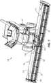
- a combine harvester 100 (or simply “combine") is shown in Fig. 1 .
- a removable header 104 is provided at a front end of the combine 100 to cut crops and feed the crops into a housing 108, or "feeder house", of the combine 100 for further harvest processing within the combine 100 (i.e., threshing of the valued crop grains from the plant stalks and separating or cleaning the crop grains from the chaff so that the crop grains alone are harvested).
- the threshing and separating can be accomplished by any one of a variety of practical mechanisms.
- the header 104 of the illustrated construction is a flexible header in which first and second wings 112 are movably supported on opposite lateral sides of a center section 116 that attaches the header 104 to the combine housing 108.
- the header 104 includes a rotatable reel 120 to engage standing crops for delivery to a table of the header 104.
- a cutterbar 124 at a forward edge of the header 104 operates (e.g., by reciprocating a plurality of overlapping knives) to cut the crop material close to the ground as it is engaged by the reel 120.
- the cutterbar 124 can be a flexible unit that allows fine terrain following throughout its length. Alternately, the cutterbar 124 can be a rigid unit that remains straight within each wing 112, allowing flexure only at the joints between the wings 112 and the center section 116.
- the header 104 is a draper header in which the table is equipped with endless belts for feeding the cut crop material into the housing 108.
- each wing 112 includes at least one side draper belt 128 operable to transmit the cut crop material inward toward the center section 116.
- the center section 116 further includes a feeder draper belt 132 operable, in a direction parallel to the combine travel direction and perpendicular to the side draper belts 128, for transmitting the cut crop material into the combine housing 108.
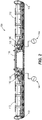
- Each of the wings 112 is pivotably supported by the center section 116 to allow independent movement of the two wings 112 with respect to the center section 116.
- a respective connection linkage 136 is provided between the center section 116 and each wing 112, as shown in Fig. 2 , to connect the same for pivoting motion.
- the connection linkages 136 can be provided toward a rearward end of the header 104, and a direct pivot connection may also be established toward the forward end between the center section 116 and each wing 112.
- the cutterbar 124 which spans both wings 112 and the center section 116 can flex to accommodate the pivoting movement of the wings 112 relative to the center section 116. This header 104 thus allows consistent low cutting of the crop material from the ground, even over uneven ground.
- Each wing 112 is mostly supported by a float arrangement including at least one resilient float element 140 coupled via a float linkage 142, while a small fraction of the weight of the wing 112 is applied to the ground (e.g., by a gauge wheel and/or skid 143 at the laterally outer end of the wing).
- Each resilient float element 140 is operable to produce a force output that varies with a position of the wing 112 with respect to the center section 116.
- Each of the resilient float elements 140 can be coupled in a manner that allows a relatively constant float force to be applied to the wing 112, despite changes in the actual force output of the resilient float element 140.
- each single-acting hydraulic cylinder is coupled via a hydraulic line to an accumulator 144 (e.g., a gas-charged accumulator) to facilitate the transfer of hydraulic fluid (e.g., liquid hydraulic oil) therebetween.
- the resilient float elements 140 can take other forms as well, including but not limited to one or more springs. Details of the float system and its operation are discussed in further detail below, following additional discussion of the connecting structures between the center section 116 and the wings 112.
- connection linkage 136 for coupling one of the wings 112 to the center section 116, with the understanding that the other wing 112 is supported by another connection linkage 136, which is a mirror image of the illustrated connection linkage 136 and conforms to the same description.
- the connection linkage 136 is provided as a four-bar linkage consisting of a frame portion 150 of the wing 112, a frame portion 154 of the center section 116, and two connecting links 158A, 158B therebetween.
- the two connecting links 158A, 158B are coupled at two respective pivots 160A, 160B on the frame portion 154 of the center section 116 and coupled at two respective pivots 164A, 164B on the frame portion 150 of the wing 112.
- the float linkage 142 carrying the resilient float element 140 is separately coupled between the frame portions 150, 154.
- the float linkage 142 passively responds to movement of the wing 112 through the connection linkage 136 to modify the supporting relationship between the resilient float element 140 and the wing 112.
- passive it is meant that it is merely reactive or responsive in a predetermined way, rather than actively or variably controlled.
- the resilient float element 140 is extensible to vary in length between a first or lower end 170 and a second or upper end 172.
- the first and second ends 170, 172 can be provided as pivots similar to those of the connection linkage 136, but are separate and spaced from every one of the pivots 160A, 160B, 164A, 164B of the connecting links 158A, 158B. Further, only one of the first and second ends 170, 172 of the resilient float element 140 is provided in fixed position on either of the frame portions 150, 154 (i.e., the upper end 172 is fixed on the wing frame portion 150).
- a primary link 176 of the float linkage 142 has a first or lower end pivotably coupled to both the first end 170 of the resilient float element 140 and a secondary link 180 of the float linkage 142.
- a second or upper end of the primary link 176 is pivotably coupled to an additional pivot, or third pivot 184, on the frame portion 154 of the center section 116.
- the third pivot 184 is spaced above and laterally outboard (to the wing side) of both of the other pivots 160A, 160B on the frame portion 154.
- the second end 172 of the resilient float element 140 defines a pivot joint with the frame portion 150 of the wing 112 and the primary link 176, between the first and second ends of the primary link 176 (i.e., between the pivot at the lower end 170 and the third pivot 184 on the frame portion 154).
- the pivot joint is retained in the illustrated construction within an elongated hole or slot 188 in which the second end 172 of the resilient float element 140, along with the frame portion 150 secured thereto, can traverse lengthwise along a distance between ends of the slot 188.
- the ends of the slot 188 can function as travel limits (e.g., maintaining each wing 112 in a range of +/- 5 degrees from horizontal neutral alignment with the center section 116).
- the secondary link 180 of the float linkage 142 is pivotably coupled to the first end 170 of the resilient float element 140 and further pivotably coupled to the wing frame portion 150 at an additional pivot, or fourth pivot 190.
- the fourth pivot 190 lies at a position on the wing frame portion 150 between the two pivots 164A, 164B at which the two connecting links 158A, 158B are coupled.
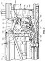
- Fig. 3 illustrates the wing 112 in a level or neutral orientation with respect to the center section 116.
- the upper end 172 of the resilient float element 140 is positioned approximately midway between opposing ends of the slot 188 defining the pivot joint. From this position, the wing 112 is free to pivot upwardly ( Fig. 4 ) or downwardly ( Fig. 5 ) in order to follow uneven ground or terrain from which crops are to be harvested.
- the float system including the resilient float element 140 for each wing 112, provides passive wing floatation that responds to uneven ground conditions naturally, without monitoring or actively adjusting the resilient float element 140.
- a ground-contact portion of the wing 112 such as the gauge wheel or skid 143, is urged upward by the ground.
- the float system responds automatically to this disturbance by allowing upward deflection of the wing 112.
- this includes an extension of the hydraulic cylinder provided as the resilient float element 140.
- the extension increases the fluid volume within the hydraulic cylinder and allows a transfer of additional hydraulic fluid from the associated accumulator 144 into the hydraulic cylinder. The hydraulic fluid pressure, and thus the stored energy, within the resilient float element 140 is thus reduced.
- the float linkage 142 operates automatically during the wing movement to compensate for the reduction in stored energy within the resilient float element 140 in order to maintain a relatively constant float force exerted on the wing 112.
- the float linkage 142 adjusts the mechanical advantage of the resilient float element 140 to the wing 112 to offset the effect of the stored energy reduction therein, thus subduing a change in an overall wing float force applied to the wing by the resilient float element.
- the wing 112 may encounter a downslope. From the upwardly pivoted position of Fig. 4 , the wing 112 may pivot back to level or, if the downslope in the area of the wing 112 is such that the ground level is below that of the center section 116, may pivot past level to a downwardly pivoted position such as that of Fig. 5 . As the wing 112 encounters the downslope, the float system responds automatically to this disturbance by allowing downward deflection of the wing 112 as the ground reaction force resulting from the applied float force tends to decrease. In the case of a hydraulic float system as illustrated, this results in retraction or compression of the resilient float actuator 140.
- the float linkage 142 operates automatically during the wing movement to compensate for the increase in stored energy within the resilient float element 140 in order to maintain a relatively constant float force exerted on the wing 112.
- the float linkage 142 adjusts the mechanical advantage of the resilient float element 140 to the wing 112 to offset the effect of the stored energy increase therein, thus subduing a change in an overall wing float force applied to the wing by the resilient float element.
- the float force on either wing 112 is normalized throughout its pivoting movement, without a requirement for active sensing or control through outside influences or actuators. Normalization of the float force occurs naturally through the movement of the float linkage 142 that varies the effectiveness of the resilient float element 140 to support the wing 112. As disclosed, the slot 188 provides adjustment of the mechanical advantage of the resilient float element 140 in a continuous or infinite manner within its operating range. Through its design, the resilient float linkage 142 provides a means for removing the float force dependence on wing position, without complicating the basic operation of the passive resilient float element 140, which itself still generates forces that are dependent on wing position.
Description
- The disclosure relates to headers for combine harvesters, and more particularly draper headers having separate lateral wings for ground following and draper belts for feeding cut crops into a feeder house.
- A prior art header is described in
US 2008/0295473 A1 , considered as generic, having a central section and wing section pivotally coupled to the central section. The wing sections are supported by a hydraulic cylinder which is either passive and acts as a damper to mediate rotation of the wings or be an active member responsive to received signals to actuate lowering or raising of the wings. In the former case, fluid pressure in the cylinder will either be reduced or increased, depending upon whether the wings pivot upwardly or downwardly, which in turn leads either to a reduction or increase in the float force exerted on the wings. - A center section is adapted for attachment to the combine and is provided with a belt operable in a rearward direction for feeding crop material into the combine. First and second wings extend in opposite lateral directions from the center section. Each of the first and second wings includes a draper belt operable to feed crop material toward the center section. The first and second wings are individually pivotably supported relative to the center section. A cutterbar is positioned at a forward edge of the draper header across the center section and the first and second wings and is operable to reciprocate for cutting crop material from the ground. The first and second wings are coupled to the center section by respective connection linkages and are furthermore supported relative to the center section by respective resilient float element. Each resilient float element is operable to produce a force output that varies with a position of the wing with respect to the center section. Each resilient float element is coupled between the center section and the respective one of the first and second wings by a respective float linkage operable through a range of positions to vary a mechanical advantage between the resilient float element and the respective wing. The movement of the float linkage reduces the mechanical advantage as the force output in the corresponding resilient float element increases, and the movement of the float linkage increases the mechanical advantage as the force output in the corresponding resilient float element decreases so that change of an overall wing float force applied to the wing by the resilient float element is subdued.
- Further aspects are set forth in the detailed description and accompanying drawings.
-
-
Fig. 1 is a perspective view of a combine harvester including a draper header having a float system according to one embodiment of the present disclosure. -
Fig. 2 is a rear view of the draper header ofFig. 1 , along with schematically illustrated hydraulic float circuits connected to resilient float elements of the draper header. -
Fig. 3 is a detail view of the draper header shown inFig. 2 , further illustrating a connection linkage and a float linkage provided between a wing and a center section of the draper header. The wing is shown in a level or neutral position. -
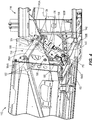
Fig. 4 is a detail view of the draper header shown inFigs. 2 and3 , illustrating the connection linkage and the float linkage with the wing in an upwardly pivoted position. -
Fig. 5 is a detail view of the draper header shown inFig. 2-4 , illustrating the connection linkage and the float linkage with the wing in a downwardly pivoted position. - Before any embodiments are explained in detail, it is to be understood that the disclosure is not limited in its application to the details of construction and the arrangement of components set forth in the following description or illustrated in the accompanying drawings.
- A combine harvester 100 (or simply "combine") is shown in
Fig. 1 . Aremovable header 104 is provided at a front end of thecombine 100 to cut crops and feed the crops into ahousing 108, or "feeder house", of thecombine 100 for further harvest processing within the combine 100 (i.e., threshing of the valued crop grains from the plant stalks and separating or cleaning the crop grains from the chaff so that the crop grains alone are harvested). The threshing and separating can be accomplished by any one of a variety of practical mechanisms. Theheader 104 of the illustrated construction is a flexible header in which first andsecond wings 112 are movably supported on opposite lateral sides of acenter section 116 that attaches theheader 104 to thecombine housing 108. Theheader 104 includes arotatable reel 120 to engage standing crops for delivery to a table of theheader 104. Acutterbar 124 at a forward edge of theheader 104 operates (e.g., by reciprocating a plurality of overlapping knives) to cut the crop material close to the ground as it is engaged by thereel 120. The cutterbar 124 can be a flexible unit that allows fine terrain following throughout its length. Alternately, thecutterbar 124 can be a rigid unit that remains straight within eachwing 112, allowing flexure only at the joints between thewings 112 and thecenter section 116. Theheader 104 is a draper header in which the table is equipped with endless belts for feeding the cut crop material into thehousing 108. For example, eachwing 112 includes at least oneside draper belt 128 operable to transmit the cut crop material inward toward thecenter section 116. Thecenter section 116 further includes afeeder draper belt 132 operable, in a direction parallel to the combine travel direction and perpendicular to theside draper belts 128, for transmitting the cut crop material into thecombine housing 108. - Each of the
wings 112 is pivotably supported by thecenter section 116 to allow independent movement of the twowings 112 with respect to thecenter section 116. In this respect, arespective connection linkage 136 is provided between thecenter section 116 and eachwing 112, as shown inFig. 2 , to connect the same for pivoting motion. Theconnection linkages 136 can be provided toward a rearward end of theheader 104, and a direct pivot connection may also be established toward the forward end between thecenter section 116 and eachwing 112. Thecutterbar 124, which spans bothwings 112 and thecenter section 116 can flex to accommodate the pivoting movement of thewings 112 relative to thecenter section 116. Thisheader 104 thus allows consistent low cutting of the crop material from the ground, even over uneven ground. Eachwing 112 is mostly supported by a float arrangement including at least oneresilient float element 140 coupled via afloat linkage 142, while a small fraction of the weight of thewing 112 is applied to the ground (e.g., by a gauge wheel and/or skid 143 at the laterally outer end of the wing). Eachresilient float element 140 is operable to produce a force output that varies with a position of thewing 112 with respect to thecenter section 116. Each of theresilient float elements 140 can be coupled in a manner that allows a relatively constant float force to be applied to thewing 112, despite changes in the actual force output of theresilient float element 140.Fig. 2 provides a general overview of the wing float system, which includes two independent float circuits or sub-systems, each of which includes the resilient float element 140 (e.g., a single-acting hydraulic cylinder). As illustrated inFig. 2 , each single-acting hydraulic cylinder is coupled via a hydraulic line to an accumulator 144 (e.g., a gas-charged accumulator) to facilitate the transfer of hydraulic fluid (e.g., liquid hydraulic oil) therebetween. Theresilient float elements 140 can take other forms as well, including but not limited to one or more springs. Details of the float system and its operation are discussed in further detail below, following additional discussion of the connecting structures between thecenter section 116 and thewings 112. -
Figs. 3-5 illustrate, in various operational positions, oneconnection linkage 136 for coupling one of thewings 112 to thecenter section 116, with the understanding that theother wing 112 is supported by anotherconnection linkage 136, which is a mirror image of the illustratedconnection linkage 136 and conforms to the same description. Theconnection linkage 136 is provided as a four-bar linkage consisting of aframe portion 150 of thewing 112, aframe portion 154 of thecenter section 116, and two connectinglinks links respective pivots frame portion 154 of thecenter section 116 and coupled at tworespective pivots frame portion 150 of thewing 112. Thefloat linkage 142 carrying theresilient float element 140 is separately coupled between theframe portions float linkage 142 passively responds to movement of thewing 112 through theconnection linkage 136 to modify the supporting relationship between theresilient float element 140 and thewing 112. By passive, it is meant that it is merely reactive or responsive in a predetermined way, rather than actively or variably controlled. - The
resilient float element 140 is extensible to vary in length between a first orlower end 170 and a second orupper end 172. The first andsecond ends connection linkage 136, but are separate and spaced from every one of thepivots links second ends resilient float element 140 is provided in fixed position on either of theframe portions 150, 154 (i.e., theupper end 172 is fixed on the wing frame portion 150). Aprimary link 176 of thefloat linkage 142 has a first or lower end pivotably coupled to both thefirst end 170 of theresilient float element 140 and asecondary link 180 of thefloat linkage 142. A second or upper end of theprimary link 176 is pivotably coupled to an additional pivot, orthird pivot 184, on theframe portion 154 of thecenter section 116. Thethird pivot 184 is spaced above and laterally outboard (to the wing side) of both of theother pivots frame portion 154. Thesecond end 172 of theresilient float element 140 defines a pivot joint with theframe portion 150 of thewing 112 and theprimary link 176, between the first and second ends of the primary link 176 (i.e., between the pivot at thelower end 170 and thethird pivot 184 on the frame portion 154). The pivot joint is retained in the illustrated construction within an elongated hole orslot 188 in which thesecond end 172 of theresilient float element 140, along with theframe portion 150 secured thereto, can traverse lengthwise along a distance between ends of theslot 188. The ends of theslot 188 can function as travel limits (e.g., maintaining eachwing 112 in a range of +/- 5 degrees from horizontal neutral alignment with the center section 116). Thesecondary link 180 of thefloat linkage 142 is pivotably coupled to thefirst end 170 of theresilient float element 140 and further pivotably coupled to thewing frame portion 150 at an additional pivot, orfourth pivot 190. Thefourth pivot 190 lies at a position on thewing frame portion 150 between the twopivots links -
Fig. 3 illustrates thewing 112 in a level or neutral orientation with respect to thecenter section 116. Theupper end 172 of theresilient float element 140 is positioned approximately midway between opposing ends of theslot 188 defining the pivot joint. From this position, thewing 112 is free to pivot upwardly (Fig. 4 ) or downwardly (Fig. 5 ) in order to follow uneven ground or terrain from which crops are to be harvested. The float system, including theresilient float element 140 for eachwing 112, provides passive wing floatation that responds to uneven ground conditions naturally, without monitoring or actively adjusting theresilient float element 140. Rather, when awing 112 encounters an upslope in the ground, a ground-contact portion of thewing 112, such as the gauge wheel orskid 143, is urged upward by the ground. The float system responds automatically to this disturbance by allowing upward deflection of thewing 112. In the case of a hydraulic float system as illustrated, this includes an extension of the hydraulic cylinder provided as theresilient float element 140. The extension increases the fluid volume within the hydraulic cylinder and allows a transfer of additional hydraulic fluid from the associatedaccumulator 144 into the hydraulic cylinder. The hydraulic fluid pressure, and thus the stored energy, within theresilient float element 140 is thus reduced. However, to avoid exerting a reduced float force to thewing 112 while thewing 112 remains on the upslope, thefloat linkage 142 operates automatically during the wing movement to compensate for the reduction in stored energy within theresilient float element 140 in order to maintain a relatively constant float force exerted on thewing 112. In other words, thefloat linkage 142 adjusts the mechanical advantage of theresilient float element 140 to thewing 112 to offset the effect of the stored energy reduction therein, thus subduing a change in an overall wing float force applied to the wing by the resilient float element. As can be seen by comparingFigs. 3 and4 , this is accomplished through the pivot joint to bring an operative axis A defined by theresilient float element 140 into closer alignment, or into alignment, with thethird pivot 184 on theframe portion 154. Thus, while the stored energy in theresilient float element 140 is reduced inFig. 4 as compared toFig. 3 , the overall float force exerted to thewing 112 can be maintained rather than varying as a dependent function of the wing position. As can be observed by comparingFigs. 3 and4 , the adjustment of the operative axis A is influenced by thesecondary link 180, which supports thefirst end 170 of theresilient float element 140 relative to thewing frame portion 150. The adjustment of the mechanical advantage is continuous through the movement of thewing 112 and has an effect on the overall wing float force that is equal and opposite to the effect of change in the stored energy within the resilient float element. - In continued operation of the
draper header 100, thewing 112 may encounter a downslope. From the upwardly pivoted position ofFig. 4 , thewing 112 may pivot back to level or, if the downslope in the area of thewing 112 is such that the ground level is below that of thecenter section 116, may pivot past level to a downwardly pivoted position such as that ofFig. 5 . As thewing 112 encounters the downslope, the float system responds automatically to this disturbance by allowing downward deflection of thewing 112 as the ground reaction force resulting from the applied float force tends to decrease. In the case of a hydraulic float system as illustrated, this results in retraction or compression of theresilient float actuator 140. The hydraulic fluid pressure, and thus the stored energy, within theresilient float element 140 is thus increased. However, to avoid exerting an increased float force to thewing 112 while thewing 112 remains on the downslope, thefloat linkage 142 operates automatically during the wing movement to compensate for the increase in stored energy within theresilient float element 140 in order to maintain a relatively constant float force exerted on thewing 112. In other words, thefloat linkage 142 adjusts the mechanical advantage of theresilient float element 140 to thewing 112 to offset the effect of the stored energy increase therein, thus subduing a change in an overall wing float force applied to the wing by the resilient float element. As can be seen by comparingFig. 4 to Fig. 3 , and alsoFig. 3 to Fig. 5 , this is accomplished through the pivot joint to move the operative axis A of theresilient float element 140 out of alignment, and increasingly further from alignment, with thethird pivot 184 on theframe portion 154. Thus, while the stored energy in theresilient float element 140 is continuously increased fromFig. 4 to Figs. 3 and to Fig. 5 , the overall float force exerted to thewing 112 can be maintained rather than varying as a dependent function of the wing position. As mentioned above, the adjustment of the operative axis A is influenced by thesecondary link 180, which supports thefirst end 170 of theresilient float element 140 relative to thewing frame portion 150. The adjustment of the mechanical advantage is continuous through the movement of thewing 112 and has an effect on the overall wing float force that is equal and opposite to the effect of change in the stored energy within the resilient float element. - In accordance with the above disclosure, it will be apparent that the float force on either
wing 112 is normalized throughout its pivoting movement, without a requirement for active sensing or control through outside influences or actuators. Normalization of the float force occurs naturally through the movement of thefloat linkage 142 that varies the effectiveness of theresilient float element 140 to support thewing 112. As disclosed, theslot 188 provides adjustment of the mechanical advantage of theresilient float element 140 in a continuous or infinite manner within its operating range. Through its design, theresilient float linkage 142 provides a means for removing the float force dependence on wing position, without complicating the basic operation of the passiveresilient float element 140, which itself still generates forces that are dependent on wing position. - Various features and advantages are set forth in the following claims.
Claims (9)
- A draper header (104) for a combine (100), the draper header (104) comprising:a center section (116) adapted for attachment to a combine (100) and provided with a belt (132) operable in a rearward direction for feeding crop material into the combine (100);first and second wings (112) extending in opposite lateral directions from the center section (116), each of the first and second wings (112) comprising a draper belt (128) operable to feed crop material toward the center section (116), wherein the first and second wings (112) are individually pivotably supported relative to the center section (116); anda cutterbar (124) positioned at a forward edge of the draper header (104) across the center section (116) and the first and second wings (112), the cutterbar (124) operable to reciprocate for cutting crop material from the ground,wherein the first and second wings (112) are coupled to the center section (116) by respective connection linkages (136) and are furthermore supported relative to the center section (116) by a respective resilient float element (140), each resilient float element (140) operable to produce a force output that varies with a position of the wing with respect to the center section (116),characterized in that each resilient float element (140) is coupled between the center section (116) and the respective one of the first and second wings (112) by a respective float linkage (142) operable through a range of positions to vary a mechanical advantage between the resilient float element (140) and the respective wing (112), andthat the movement of the float linkage (142) reduces the mechanical advantage as the force output in the corresponding resilient float element (140) increases, and the movement of the float linkage (142) increases the mechanical advantage as the force output in the corresponding resilient float element (140) decreases so that change of an overall wing float force applied to the wing (112) by the resilient float element (140) is subdued.
- The draper header (104) of claim 1, wherein each of the resilient float element (140) includes a single-acting hydraulic cylinder coupled to a gas-charged accumulator (144).
- The draper header (104) of claim 1, wherein each respective connection linkage (136) is provided as a four-bar linkage consisting of a frame portion (150) of the wing (112), a frame portion (154) of the center section (116), and two connecting links (158A, 158B) therebetween.
- The draper header (104) of claim 3, wherein the two connecting links (158A, 158B) are coupled at two pivots (160A, 164B) on the frame portion (154) of the center section (116).
- The draper header (104) of claim 4, wherein a primary link (176) of each respective float linkage (142) has a first end pivotably coupled to both a first end of the resilient float element (140) and a secondary link (180) of the float linkage (142), and a second end of the primary link (176) is pivotably coupled to a third pivot (160B) on the frame portion (154) of the center section (116).
- The draper header (104) of claim 5, wherein a second end of the resilient float element (140) defines a pivot joint with the frame portion (150) of the wing (112), and the pivot joint is constrained within a slot (188) provided in the primary link (176) between the first and second ends.
- The draper header (104) of claim 6, wherein the movement of the float linkage (142) increases the mechanical advantage by bringing the pivot joint (160A, 160B) closer to alignment between the first and second ends of the float linkage (142) primary link.
- The draper header (104) of claim 5, wherein the secondary link (180) of the float linkage (142) is pivotably coupled to the frame portion (150) of the wing (112) at a position between two pivots (160A, 160B) at which the two connecting links (158A, 158B) are coupled to the frame portion (150) of the wing (112).
- The draper header (104) of claim 1, wherein the respective float linkages (142) and the respective resilient float elements (140) are passive, the operation of which is dictated by the position of the respective one of the first and second wings (112) with respect to the center section (116).
Applications Claiming Priority (1)
| Application Number | Priority Date | Filing Date | Title |
|---|---|---|---|
| US15/785,092 US10433486B2 (en) | 2017-10-16 | 2017-10-16 | System and method for wing float on a combine draper header |
Publications (2)
| Publication Number | Publication Date |
|---|---|
| EP3469876A1 EP3469876A1 (en) | 2019-04-17 |
| EP3469876B1 true EP3469876B1 (en) | 2020-07-15 |
Family
ID=63857825
Family Applications (1)
| Application Number | Title | Priority Date | Filing Date |
|---|---|---|---|
| EP18200409.3A Active EP3469876B1 (en) | 2017-10-16 | 2018-10-15 | System for wing float on a combine draper header |
Country Status (3)
| Country | Link |
|---|---|
| US (1) | US10433486B2 (en) |
| EP (1) | EP3469876B1 (en) |
| BR (1) | BR102018071042B1 (en) |
Families Citing this family (16)
| Publication number | Priority date | Publication date | Assignee | Title |
|---|---|---|---|---|
| US10617059B2 (en) * | 2016-06-21 | 2020-04-14 | Macdon Industries Ltd. | Crop machine with an electronically controlled hydraulic cylinder flotation system |
| US10433483B2 (en) * | 2017-08-21 | 2019-10-08 | Cnh Industrial America Llc | Agricultural header with one or more movable wing sections |
| WO2019136281A1 (en) * | 2018-01-04 | 2019-07-11 | Cnh Industrial America Llc | Agricultural harvester with header having conformable portions |
| US10813289B2 (en) * | 2018-06-05 | 2020-10-27 | Deere & Company | Single top beam folding corn head mainframe |
| US10952375B2 (en) * | 2018-06-29 | 2021-03-23 | Macdon Industries Ltd | Crop header with wing balance calibration |
| US11297765B2 (en) * | 2018-07-02 | 2022-04-12 | Deere & Company | Suspension compliance to reduce frame loading |
| US20220007577A1 (en) * | 2018-11-16 | 2022-01-13 | Cnh Industrial America Llc | Header with modular rigid frame |
| US11224164B2 (en) * | 2019-04-23 | 2022-01-18 | Deere & Company | Damped float response on an agricultural harvester |
| US11219162B2 (en) * | 2019-04-23 | 2022-01-11 | Deere & Company | Controlled header lowering on an agricultural harvester |
| US11191212B2 (en) * | 2019-04-23 | 2021-12-07 | Deere & Company | Controlled float on an agricultural harvester for header leveling |
| US11064654B2 (en) * | 2019-05-01 | 2021-07-20 | Deere & Company | Float adjustment |
| CA190283S (en) * | 2019-05-09 | 2021-02-26 | Deere & Co | Fender for an agricultural machine |
| US11019770B2 (en) * | 2019-05-28 | 2021-06-01 | Deere & Company | Harvester wing leveling configuration |
| US11627701B2 (en) * | 2019-10-31 | 2023-04-18 | Deere & Company | Agricultural header with flexible joint |
| US11234368B2 (en) * | 2019-12-23 | 2022-02-01 | Cnh Industrial America Llc | Cutter bar assembly for a harvester |
| US11375658B2 (en) * | 2019-12-23 | 2022-07-05 | Cnh Industrial America Llc | System and method for leveling a cutter bar of a harvester |
Citations (3)
| Publication number | Priority date | Publication date | Assignee | Title |
|---|---|---|---|---|
| US6675568B2 (en) | 2001-06-18 | 2004-01-13 | Macdon Industries Ltd. | Multi-section header with flexible crop cutting knife |
| US20080295473A1 (en) | 2007-06-04 | 2008-12-04 | Claas Selbstfahrende Erntemaschinen Gmbh | Winged header apparatus and method for a combine |
| EP3153004B1 (en) | 2015-10-05 | 2018-03-28 | Carl Geringhoff GmbH & Co. KG | Cutter with adjustable side frame relief |
Family Cites Families (56)
| Publication number | Priority date | Publication date | Assignee | Title |
|---|---|---|---|---|
| US2608041A (en) | 1947-01-24 | 1952-08-26 | Case Co J I | Conveying means for harvester headers |
| NL6414183A (en) | 1964-12-05 | 1966-06-06 | ||
| NL6903371A (en) | 1969-03-05 | 1970-09-08 | ||
| US4487004A (en) * | 1983-06-03 | 1984-12-11 | Kejr Melvin P | Combine harvester apparatus |
| CA2110775C (en) | 1993-12-06 | 1999-03-02 | Gregory J. Honey | A feeder adapter for mounting a combine header to a feeder housing of a combine |
| DE19523255A1 (en) | 1995-06-27 | 1997-01-02 | Claas Saulgau Gmbh | Header on agricultural machines for picking up and moving on straw crops, for example maize plants |
| US5577563A (en) | 1995-07-27 | 1996-11-26 | Holen; Kurt | Stack-folding toolbar with floating wings |
| US5673543A (en) | 1996-01-04 | 1997-10-07 | Byron Enterprises, Inc | Foldable corn head with unobstructed auger |
| US5724798A (en) | 1996-07-08 | 1998-03-10 | Byron Enterprises Inc. | Latch for a folding corn head |
| US6003615A (en) | 1998-08-19 | 1999-12-21 | Moore; Paul O. | Stacking tool bar including a wing flex structure |
| US6202397B1 (en) | 1999-05-27 | 2001-03-20 | Deere & Company | Draper belt tensioning mechanism for a harvesting platform |
| DE10039097A1 (en) | 2000-08-07 | 2002-02-21 | Claas Saulgau Gmbh | Method and device for pivoting the dividers of multi-part agricultural harvesters |
| HUP0300512A2 (en) | 2002-03-28 | 2004-09-28 | Claas Saulgau Gmbh | Reaper knife |
| DE10221983A1 (en) | 2002-05-17 | 2003-11-27 | Kemper Gmbh Maschf | header |
| DE10250337A1 (en) | 2002-10-29 | 2004-05-19 | Maschinenfabrik Kemper Gmbh & Co. Kg | Adjustment device for a header |
| US6865871B2 (en) | 2003-07-14 | 2005-03-15 | Macdon Industries Ltd. | Crop feed arrangement for the header of a combine harvester |
| US7168226B2 (en) | 2004-03-31 | 2007-01-30 | Cnh America Llc | Independent hydraulic header lift and flotation system |
| US7392646B2 (en) | 2004-06-16 | 2008-07-01 | Macdon Industries Ltd. | Reversible feed roller with radially extendible fingers |
| US7467668B2 (en) | 2005-03-31 | 2008-12-23 | Kimball Von D | Transport lock joint for stack fold toolbar |
| US20080276590A1 (en) | 2006-02-10 | 2008-11-13 | Agco Corporation | Flexible draper and cutter bar with tilt arm for cutterbar drive |
| US20070193243A1 (en) | 2006-02-10 | 2007-08-23 | Schmidt James R | Combine Harvester Draper Header Having Flexible Cutterbar |
| US7540130B2 (en) | 2006-03-02 | 2009-06-02 | Deere & Company | Height control for a multi-section cutting platform in an agricultural harvesting machine |
| US7918076B2 (en) | 2006-09-25 | 2011-04-05 | Macdon Industries Ltd. | Device for maintaining wing balance on a multi-section header |
| CA2572274C (en) | 2006-12-29 | 2014-05-27 | Honey Bee Manufacturing Ltd. | Rock trap for combine header |
| US7587885B2 (en) | 2007-06-04 | 2009-09-15 | Claas Selbstfahrende Emtemaschinen Gmbh | Central auger crop feed system for a harvester |
| US7921627B2 (en) | 2008-05-09 | 2011-04-12 | Agco Corporation | Interlocking belt guards for a draper header |
| US7788891B2 (en) | 2008-06-27 | 2010-09-07 | Deere & Company | Endless belt mounting configuration for an agricultural harvester |
| US8281561B2 (en) | 2010-08-17 | 2012-10-09 | Deere & Company | Flexible draper belt drive for an agricultural harvesting machine |
| DE102010037131A1 (en) | 2010-08-24 | 2012-03-01 | Claas Selbstfahrende Erntemaschinen Gmbh | cutting |
| US8087224B1 (en) | 2010-09-16 | 2012-01-03 | Deere & Company | Flexible draper platform with pivot geometry |
| US7992372B1 (en) * | 2010-09-16 | 2011-08-09 | Deere & Company | Draper platform with breakaway joint |
| US8336280B2 (en) | 2011-05-20 | 2012-12-25 | Deere & Company | Pivoting center conveyor for draper platform |
| US8544250B2 (en) | 2011-10-25 | 2013-10-01 | Deere & Company | Draper platform with center conveyor and method of replacing the center conveyor belt |
| ITPD20120242A1 (en) | 2012-08-06 | 2014-02-07 | Cressoni S P A Flli | FOLDABLE HEAD FOR BRAIDING AND / OR HARVESTING MACHINE AND FILLING METHOD OF A BANNER MILLING AND / OR HARVESTING MACHINE |
| US8695315B2 (en) | 2012-08-09 | 2014-04-15 | Deere & Company | Draper header with pivoting side draper conveyors |
| US9198353B2 (en) * | 2012-09-20 | 2015-12-01 | Deere & Company | Hinged row crop harvesting head |
| US9072222B2 (en) | 2012-09-20 | 2015-07-07 | Deere & Company | Self-centering cover for hinged row crop harvesting head |
| DE102013100322A1 (en) | 2013-01-14 | 2014-07-17 | Claas Selbstfahrende Erntemaschinen Gmbh | cutting |
| US9198349B2 (en) | 2013-07-12 | 2015-12-01 | Deere & Company | Articulated harvesting head ground force control circuit |
| US9144199B2 (en) | 2013-08-30 | 2015-09-29 | Deere & Company | Articulated harvesting head load sensor arrangement |
| DE102014009161B4 (en) | 2014-06-25 | 2023-01-26 | Carl Geringhoff Gmbh & Co. Kg | Cutting unit with central part and adjustable side parts |
| DE102014216112A1 (en) | 2014-08-13 | 2016-02-18 | Walter Schmid | Self-propelled harvester |
| US9788486B2 (en) | 2014-12-30 | 2017-10-17 | Agco Corporation | Grain header with swathing and chopping capability |
| BR102016005189B1 (en) | 2015-03-13 | 2020-11-17 | Cnh Industrial Belgium Nv | AGRICULTURAL HARVESTER |
| US9668412B2 (en) | 2015-05-01 | 2017-06-06 | Deere & Company | Harvesting head height control circuit |
| US20160360699A1 (en) | 2015-06-10 | 2016-12-15 | Jose Luis Allochis | Conveyor belt tensing apparatus for a harvesting header |
| DE102015118143A1 (en) | 2015-10-23 | 2017-04-27 | Arnold Jäger Holding GmbH | Cam belts, especially for agricultural machines |
| BE1023925B1 (en) | 2016-03-01 | 2017-09-13 | Cnh Industrial Belgium Nv | FEEDING DEVICE FOR CUTTER |
| BE1024333B1 (en) | 2016-06-23 | 2018-02-01 | Cnh Industrial Belgium Nv | Cutting bar support for a harvesting machine |
| US10070575B2 (en) | 2016-08-05 | 2018-09-11 | Cnh Industrial America Llc | Agricultural machine with folding header |
| US20180070526A1 (en) | 2016-09-13 | 2018-03-15 | Cnh Industrial Canada, Ltd. | Apparatus and method to minimize transport dimensions of agricultural implements |
| DE102016118174A1 (en) | 2016-09-26 | 2018-03-29 | Claas Selbstfahrende Erntemaschinen Gmbh | cutting |
| US10375881B2 (en) | 2017-05-23 | 2019-08-13 | Cnh Industrial America Llc | Agricultural machine with sectional header |
| US10299437B2 (en) | 2017-07-17 | 2019-05-28 | Cnh Industrial America Llc | Header for an agricultural vehicle with deformable supports |
| US10820509B2 (en) | 2017-08-08 | 2020-11-03 | Cnh Industrial America Llc | Foldable corn head |
| US10433483B2 (en) * | 2017-08-21 | 2019-10-08 | Cnh Industrial America Llc | Agricultural header with one or more movable wing sections |
-
2017
- 2017-10-16 US US15/785,092 patent/US10433486B2/en active Active
-
2018
- 2018-10-11 BR BR102018071042-7A patent/BR102018071042B1/en active IP Right Grant
- 2018-10-15 EP EP18200409.3A patent/EP3469876B1/en active Active
Patent Citations (3)
| Publication number | Priority date | Publication date | Assignee | Title |
|---|---|---|---|---|
| US6675568B2 (en) | 2001-06-18 | 2004-01-13 | Macdon Industries Ltd. | Multi-section header with flexible crop cutting knife |
| US20080295473A1 (en) | 2007-06-04 | 2008-12-04 | Claas Selbstfahrende Erntemaschinen Gmbh | Winged header apparatus and method for a combine |
| EP3153004B1 (en) | 2015-10-05 | 2018-03-28 | Carl Geringhoff GmbH & Co. KG | Cutter with adjustable side frame relief |
Also Published As
| Publication number | Publication date |
|---|---|
| EP3469876A1 (en) | 2019-04-17 |
| BR102018071042B1 (en) | 2023-11-14 |
| BR102018071042A2 (en) | 2019-06-04 |
| US20190110402A1 (en) | 2019-04-18 |
| US10433486B2 (en) | 2019-10-08 |
Similar Documents
| Publication | Publication Date | Title |
|---|---|---|
| EP3469876B1 (en) | System for wing float on a combine draper header | |
| EP3473076B1 (en) | Self-contained combine draper wing leveler | |
| EP3469878B1 (en) | Roll center for harvester attachment frame control arms | |
| US11778946B2 (en) | Flexible header with sectional height adjustment | |
| EP3446558B2 (en) | Agricultural header with one or more movable wing sections | |
| US7726111B2 (en) | Suspension system for a belt pickup header in an agricultural harvester | |
| EP1401256B1 (en) | Multi-section header with flexible crop cutting knife | |
| EP2374344B1 (en) | Agricultural plant cutting header with fore and aft adjustable flexible cutterbar having automatic preload adjustment | |
| US8051633B2 (en) | Cutterbar adjustment support for a crop harvesting header | |
| AU2002257470A1 (en) | Multi-section header with flexible crop cutting knife | |
| EP3466241B1 (en) | Agricultural harvesting head with float arm pivots below reciprocating knives | |
| EP3610716B1 (en) | System and method for ground following of a combine header with flexible cutter bar | |
| US11553645B2 (en) | Flex arm air bag linkage | |
| CA3079836A1 (en) | Float adjustment | |
| EP3811763B1 (en) | Cutter bar support linkage | |
| EP3815505B1 (en) | Torsion balanced harvester head | |
| US20230240179A1 (en) | Agricultural header float arm system |
Legal Events
| Date | Code | Title | Description |
|---|---|---|---|
| PUAI | Public reference made under article 153(3) epc to a published international application that has entered the european phase |
Free format text: ORIGINAL CODE: 0009012 |
|
| STAA | Information on the status of an ep patent application or granted ep patent |
Free format text: STATUS: THE APPLICATION HAS BEEN PUBLISHED |
|
| AK | Designated contracting states |
Kind code of ref document: A1 Designated state(s): AL AT BE BG CH CY CZ DE DK EE ES FI FR GB GR HR HU IE IS IT LI LT LU LV MC MK MT NL NO PL PT RO RS SE SI SK SM TR |
|
| AX | Request for extension of the european patent |
Extension state: BA ME |
|
| TPAC | Observations filed by third parties |
Free format text: ORIGINAL CODE: EPIDOSNTIPA |
|
| STAA | Information on the status of an ep patent application or granted ep patent |
Free format text: STATUS: REQUEST FOR EXAMINATION WAS MADE |
|
| 17P | Request for examination filed |
Effective date: 20191017 |
|
| RBV | Designated contracting states (corrected) |
Designated state(s): AL AT BE BG CH CY CZ DE DK EE ES FI FR GB GR HR HU IE IS IT LI LT LU LV MC MK MT NL NO PL PT RO RS SE SI SK SM TR |
|
| GRAP | Despatch of communication of intention to grant a patent |
Free format text: ORIGINAL CODE: EPIDOSNIGR1 |
|
| STAA | Information on the status of an ep patent application or granted ep patent |
Free format text: STATUS: GRANT OF PATENT IS INTENDED |
|
| INTG | Intention to grant announced |
Effective date: 20200214 |
|
| GRAS | Grant fee paid |
Free format text: ORIGINAL CODE: EPIDOSNIGR3 |
|
| GRAA | (expected) grant |
Free format text: ORIGINAL CODE: 0009210 |
|
| STAA | Information on the status of an ep patent application or granted ep patent |
Free format text: STATUS: THE PATENT HAS BEEN GRANTED |
|
| AK | Designated contracting states |
Kind code of ref document: B1 Designated state(s): AL AT BE BG CH CY CZ DE DK EE ES FI FR GB GR HR HU IE IS IT LI LT LU LV MC MK MT NL NO PL PT RO RS SE SI SK SM TR |
|
| REG | Reference to a national code |
Ref country code: CH Ref legal event code: EP Ref country code: GB Ref legal event code: FG4D |
|
| REG | Reference to a national code |
Ref country code: IE Ref legal event code: FG4D |
|
| REG | Reference to a national code |
Ref country code: DE Ref legal event code: R096 Ref document number: 602018006042 Country of ref document: DE |
|
| REG | Reference to a national code |
Ref country code: AT Ref legal event code: REF Ref document number: 1289928 Country of ref document: AT Kind code of ref document: T Effective date: 20200815 |
|
| REG | Reference to a national code |
Ref country code: LT Ref legal event code: MG4D |
|
| REG | Reference to a national code |
Ref country code: AT Ref legal event code: MK05 Ref document number: 1289928 Country of ref document: AT Kind code of ref document: T Effective date: 20200715 |
|
| REG | Reference to a national code |
Ref country code: NL Ref legal event code: MP Effective date: 20200715 |
|
| PG25 | Lapsed in a contracting state [announced via postgrant information from national office to epo] |
Ref country code: LT Free format text: LAPSE BECAUSE OF FAILURE TO SUBMIT A TRANSLATION OF THE DESCRIPTION OR TO PAY THE FEE WITHIN THE PRESCRIBED TIME-LIMIT Effective date: 20200715 Ref country code: ES Free format text: LAPSE BECAUSE OF FAILURE TO SUBMIT A TRANSLATION OF THE DESCRIPTION OR TO PAY THE FEE WITHIN THE PRESCRIBED TIME-LIMIT Effective date: 20200715 Ref country code: PT Free format text: LAPSE BECAUSE OF FAILURE TO SUBMIT A TRANSLATION OF THE DESCRIPTION OR TO PAY THE FEE WITHIN THE PRESCRIBED TIME-LIMIT Effective date: 20201116 Ref country code: BG Free format text: LAPSE BECAUSE OF FAILURE TO SUBMIT A TRANSLATION OF THE DESCRIPTION OR TO PAY THE FEE WITHIN THE PRESCRIBED TIME-LIMIT Effective date: 20201015 Ref country code: SE Free format text: LAPSE BECAUSE OF FAILURE TO SUBMIT A TRANSLATION OF THE DESCRIPTION OR TO PAY THE FEE WITHIN THE PRESCRIBED TIME-LIMIT Effective date: 20200715 Ref country code: AT Free format text: LAPSE BECAUSE OF FAILURE TO SUBMIT A TRANSLATION OF THE DESCRIPTION OR TO PAY THE FEE WITHIN THE PRESCRIBED TIME-LIMIT Effective date: 20200715 Ref country code: HR Free format text: LAPSE BECAUSE OF FAILURE TO SUBMIT A TRANSLATION OF THE DESCRIPTION OR TO PAY THE FEE WITHIN THE PRESCRIBED TIME-LIMIT Effective date: 20200715 Ref country code: GR Free format text: LAPSE BECAUSE OF FAILURE TO SUBMIT A TRANSLATION OF THE DESCRIPTION OR TO PAY THE FEE WITHIN THE PRESCRIBED TIME-LIMIT Effective date: 20201016 Ref country code: NO Free format text: LAPSE BECAUSE OF FAILURE TO SUBMIT A TRANSLATION OF THE DESCRIPTION OR TO PAY THE FEE WITHIN THE PRESCRIBED TIME-LIMIT Effective date: 20201015 Ref country code: FI Free format text: LAPSE BECAUSE OF FAILURE TO SUBMIT A TRANSLATION OF THE DESCRIPTION OR TO PAY THE FEE WITHIN THE PRESCRIBED TIME-LIMIT Effective date: 20200715 |
|
| PG25 | Lapsed in a contracting state [announced via postgrant information from national office to epo] |
Ref country code: RS Free format text: LAPSE BECAUSE OF FAILURE TO SUBMIT A TRANSLATION OF THE DESCRIPTION OR TO PAY THE FEE WITHIN THE PRESCRIBED TIME-LIMIT Effective date: 20200715 Ref country code: LV Free format text: LAPSE BECAUSE OF FAILURE TO SUBMIT A TRANSLATION OF THE DESCRIPTION OR TO PAY THE FEE WITHIN THE PRESCRIBED TIME-LIMIT Effective date: 20200715 Ref country code: PL Free format text: LAPSE BECAUSE OF FAILURE TO SUBMIT A TRANSLATION OF THE DESCRIPTION OR TO PAY THE FEE WITHIN THE PRESCRIBED TIME-LIMIT Effective date: 20200715 Ref country code: IS Free format text: LAPSE BECAUSE OF FAILURE TO SUBMIT A TRANSLATION OF THE DESCRIPTION OR TO PAY THE FEE WITHIN THE PRESCRIBED TIME-LIMIT Effective date: 20201115 |
|
| PG25 | Lapsed in a contracting state [announced via postgrant information from national office to epo] |
Ref country code: NL Free format text: LAPSE BECAUSE OF FAILURE TO SUBMIT A TRANSLATION OF THE DESCRIPTION OR TO PAY THE FEE WITHIN THE PRESCRIBED TIME-LIMIT Effective date: 20200715 |
|
| REG | Reference to a national code |
Ref country code: DE Ref legal event code: R026 Ref document number: 602018006042 Country of ref document: DE |
|
| PLBI | Opposition filed |
Free format text: ORIGINAL CODE: 0009260 |
|
| PG25 | Lapsed in a contracting state [announced via postgrant information from national office to epo] |
Ref country code: CZ Free format text: LAPSE BECAUSE OF FAILURE TO SUBMIT A TRANSLATION OF THE DESCRIPTION OR TO PAY THE FEE WITHIN THE PRESCRIBED TIME-LIMIT Effective date: 20200715 Ref country code: DK Free format text: LAPSE BECAUSE OF FAILURE TO SUBMIT A TRANSLATION OF THE DESCRIPTION OR TO PAY THE FEE WITHIN THE PRESCRIBED TIME-LIMIT Effective date: 20200715 Ref country code: RO Free format text: LAPSE BECAUSE OF FAILURE TO SUBMIT A TRANSLATION OF THE DESCRIPTION OR TO PAY THE FEE WITHIN THE PRESCRIBED TIME-LIMIT Effective date: 20200715 Ref country code: EE Free format text: LAPSE BECAUSE OF FAILURE TO SUBMIT A TRANSLATION OF THE DESCRIPTION OR TO PAY THE FEE WITHIN THE PRESCRIBED TIME-LIMIT Effective date: 20200715 Ref country code: SM Free format text: LAPSE BECAUSE OF FAILURE TO SUBMIT A TRANSLATION OF THE DESCRIPTION OR TO PAY THE FEE WITHIN THE PRESCRIBED TIME-LIMIT Effective date: 20200715 Ref country code: IT Free format text: LAPSE BECAUSE OF FAILURE TO SUBMIT A TRANSLATION OF THE DESCRIPTION OR TO PAY THE FEE WITHIN THE PRESCRIBED TIME-LIMIT Effective date: 20200715 |
|
| PLAX | Notice of opposition and request to file observation + time limit sent |
Free format text: ORIGINAL CODE: EPIDOSNOBS2 |
|
| 26 | Opposition filed |
Opponent name: CARL GERINGHOFF GMBH & CO. KG Effective date: 20210413 |
|
| PG25 | Lapsed in a contracting state [announced via postgrant information from national office to epo] |
Ref country code: AL Free format text: LAPSE BECAUSE OF FAILURE TO SUBMIT A TRANSLATION OF THE DESCRIPTION OR TO PAY THE FEE WITHIN THE PRESCRIBED TIME-LIMIT Effective date: 20200715 |
|
| PG25 | Lapsed in a contracting state [announced via postgrant information from national office to epo] |
Ref country code: MC Free format text: LAPSE BECAUSE OF FAILURE TO SUBMIT A TRANSLATION OF THE DESCRIPTION OR TO PAY THE FEE WITHIN THE PRESCRIBED TIME-LIMIT Effective date: 20200715 Ref country code: SK Free format text: LAPSE BECAUSE OF FAILURE TO SUBMIT A TRANSLATION OF THE DESCRIPTION OR TO PAY THE FEE WITHIN THE PRESCRIBED TIME-LIMIT Effective date: 20200715 Ref country code: LU Free format text: LAPSE BECAUSE OF NON-PAYMENT OF DUE FEES Effective date: 20201015 |
|
| REG | Reference to a national code |
Ref country code: BE Ref legal event code: MM Effective date: 20201031 |
|
| PG25 | Lapsed in a contracting state [announced via postgrant information from national office to epo] |
Ref country code: FR Free format text: LAPSE BECAUSE OF NON-PAYMENT OF DUE FEES Effective date: 20201031 |
|
| PG25 | Lapsed in a contracting state [announced via postgrant information from national office to epo] |
Ref country code: SI Free format text: LAPSE BECAUSE OF FAILURE TO SUBMIT A TRANSLATION OF THE DESCRIPTION OR TO PAY THE FEE WITHIN THE PRESCRIBED TIME-LIMIT Effective date: 20200715 Ref country code: BE Free format text: LAPSE BECAUSE OF NON-PAYMENT OF DUE FEES Effective date: 20201031 |
|
| PLBB | Reply of patent proprietor to notice(s) of opposition received |
Free format text: ORIGINAL CODE: EPIDOSNOBS3 |
|
| PG25 | Lapsed in a contracting state [announced via postgrant information from national office to epo] |
Ref country code: IE Free format text: LAPSE BECAUSE OF NON-PAYMENT OF DUE FEES Effective date: 20201015 |
|
| PLBP | Opposition withdrawn |
Free format text: ORIGINAL CODE: 0009264 |
|
| PLBD | Termination of opposition procedure: decision despatched |
Free format text: ORIGINAL CODE: EPIDOSNOPC1 |
|
| REG | Reference to a national code |
Ref country code: DE Ref legal event code: R100 Ref document number: 602018006042 Country of ref document: DE |
|
| REG | Reference to a national code |
Ref country code: CH Ref legal event code: PL |
|
| PG25 | Lapsed in a contracting state [announced via postgrant information from national office to epo] |
Ref country code: TR Free format text: LAPSE BECAUSE OF FAILURE TO SUBMIT A TRANSLATION OF THE DESCRIPTION OR TO PAY THE FEE WITHIN THE PRESCRIBED TIME-LIMIT Effective date: 20200715 Ref country code: MT Free format text: LAPSE BECAUSE OF FAILURE TO SUBMIT A TRANSLATION OF THE DESCRIPTION OR TO PAY THE FEE WITHIN THE PRESCRIBED TIME-LIMIT Effective date: 20200715 Ref country code: CY Free format text: LAPSE BECAUSE OF FAILURE TO SUBMIT A TRANSLATION OF THE DESCRIPTION OR TO PAY THE FEE WITHIN THE PRESCRIBED TIME-LIMIT Effective date: 20200715 |
|
| PG25 | Lapsed in a contracting state [announced via postgrant information from national office to epo] |
Ref country code: MK Free format text: LAPSE BECAUSE OF FAILURE TO SUBMIT A TRANSLATION OF THE DESCRIPTION OR TO PAY THE FEE WITHIN THE PRESCRIBED TIME-LIMIT Effective date: 20200715 |
|
| PLBM | Termination of opposition procedure: date of legal effect published |
Free format text: ORIGINAL CODE: 0009276 |
|
| PG25 | Lapsed in a contracting state [announced via postgrant information from national office to epo] |
Ref country code: LI Free format text: LAPSE BECAUSE OF NON-PAYMENT OF DUE FEES Effective date: 20211031 Ref country code: CH Free format text: LAPSE BECAUSE OF NON-PAYMENT OF DUE FEES Effective date: 20211031 |
|
| 27C | Opposition proceedings terminated |
Effective date: 20220514 |
|
| GBPC | Gb: european patent ceased through non-payment of renewal fee |
Effective date: 20221015 |
|
| PG25 | Lapsed in a contracting state [announced via postgrant information from national office to epo] |
Ref country code: GB Free format text: LAPSE BECAUSE OF NON-PAYMENT OF DUE FEES Effective date: 20221015 |
|
| PGFP | Annual fee paid to national office [announced via postgrant information from national office to epo] |
Ref country code: DE Payment date: 20230920 Year of fee payment: 6 |