EP3467590A1 - Beleuchtungssystem für die euv-projektionslithographie - Google Patents
Beleuchtungssystem für die euv-projektionslithographie Download PDFInfo
- Publication number
- EP3467590A1 EP3467590A1 EP18205398.3A EP18205398A EP3467590A1 EP 3467590 A1 EP3467590 A1 EP 3467590A1 EP 18205398 A EP18205398 A EP 18205398A EP 3467590 A1 EP3467590 A1 EP 3467590A1
- Authority
- EP
- European Patent Office
- Prior art keywords
- euv
- mirror
- optics
- mirrors
- optical system
- Prior art date
- Legal status (The legal status is an assumption and is not a legal conclusion. Google has not performed a legal analysis and makes no representation as to the accuracy of the status listed.)
- Pending
Links
Images


Classifications
-
- G—PHYSICS
- G03—PHOTOGRAPHY; CINEMATOGRAPHY; ANALOGOUS TECHNIQUES USING WAVES OTHER THAN OPTICAL WAVES; ELECTROGRAPHY; HOLOGRAPHY
- G03F—PHOTOMECHANICAL PRODUCTION OF TEXTURED OR PATTERNED SURFACES, e.g. FOR PRINTING, FOR PROCESSING OF SEMICONDUCTOR DEVICES; MATERIALS THEREFOR; ORIGINALS THEREFOR; APPARATUS SPECIALLY ADAPTED THEREFOR
- G03F7/00—Photomechanical, e.g. photolithographic, production of textured or patterned surfaces, e.g. printing surfaces; Materials therefor, e.g. comprising photoresists; Apparatus specially adapted therefor
- G03F7/20—Exposure; Apparatus therefor
- G03F7/2002—Exposure; Apparatus therefor with visible light or UV light, through an original having an opaque pattern on a transparent support, e.g. film printing, projection printing; by reflection of visible or UV light from an original such as a printed image
- G03F7/2004—Exposure; Apparatus therefor with visible light or UV light, through an original having an opaque pattern on a transparent support, e.g. film printing, projection printing; by reflection of visible or UV light from an original such as a printed image characterised by the use of a particular light source, e.g. fluorescent lamps or deep UV light
- G03F7/2006—Exposure; Apparatus therefor with visible light or UV light, through an original having an opaque pattern on a transparent support, e.g. film printing, projection printing; by reflection of visible or UV light from an original such as a printed image characterised by the use of a particular light source, e.g. fluorescent lamps or deep UV light using coherent light; using polarised light
-
- G—PHYSICS
- G03—PHOTOGRAPHY; CINEMATOGRAPHY; ANALOGOUS TECHNIQUES USING WAVES OTHER THAN OPTICAL WAVES; ELECTROGRAPHY; HOLOGRAPHY
- G03F—PHOTOMECHANICAL PRODUCTION OF TEXTURED OR PATTERNED SURFACES, e.g. FOR PRINTING, FOR PROCESSING OF SEMICONDUCTOR DEVICES; MATERIALS THEREFOR; ORIGINALS THEREFOR; APPARATUS SPECIALLY ADAPTED THEREFOR
- G03F7/00—Photomechanical, e.g. photolithographic, production of textured or patterned surfaces, e.g. printing surfaces; Materials therefor, e.g. comprising photoresists; Apparatus specially adapted therefor
- G03F7/70—Microphotolithographic exposure; Apparatus therefor
- G03F7/70058—Mask illumination systems
- G03F7/7015—Details of optical elements
- G03F7/70183—Zoom systems for adjusting beam diameter
-
- G—PHYSICS
- G03—PHOTOGRAPHY; CINEMATOGRAPHY; ANALOGOUS TECHNIQUES USING WAVES OTHER THAN OPTICAL WAVES; ELECTROGRAPHY; HOLOGRAPHY
- G03F—PHOTOMECHANICAL PRODUCTION OF TEXTURED OR PATTERNED SURFACES, e.g. FOR PRINTING, FOR PROCESSING OF SEMICONDUCTOR DEVICES; MATERIALS THEREFOR; ORIGINALS THEREFOR; APPARATUS SPECIALLY ADAPTED THEREFOR
- G03F7/00—Photomechanical, e.g. photolithographic, production of textured or patterned surfaces, e.g. printing surfaces; Materials therefor, e.g. comprising photoresists; Apparatus specially adapted therefor
- G03F7/70—Microphotolithographic exposure; Apparatus therefor
- G03F7/70008—Production of exposure light, i.e. light sources
- G03F7/70033—Production of exposure light, i.e. light sources by plasma extreme ultraviolet [EUV] sources
-
- G—PHYSICS
- G03—PHOTOGRAPHY; CINEMATOGRAPHY; ANALOGOUS TECHNIQUES USING WAVES OTHER THAN OPTICAL WAVES; ELECTROGRAPHY; HOLOGRAPHY
- G03F—PHOTOMECHANICAL PRODUCTION OF TEXTURED OR PATTERNED SURFACES, e.g. FOR PRINTING, FOR PROCESSING OF SEMICONDUCTOR DEVICES; MATERIALS THEREFOR; ORIGINALS THEREFOR; APPARATUS SPECIALLY ADAPTED THEREFOR
- G03F7/00—Photomechanical, e.g. photolithographic, production of textured or patterned surfaces, e.g. printing surfaces; Materials therefor, e.g. comprising photoresists; Apparatus specially adapted therefor
- G03F7/70—Microphotolithographic exposure; Apparatus therefor
- G03F7/70058—Mask illumination systems
- G03F7/70191—Optical correction elements, filters or phase plates for controlling intensity, wavelength, polarisation, phase or the like
-
- G—PHYSICS
- G03—PHOTOGRAPHY; CINEMATOGRAPHY; ANALOGOUS TECHNIQUES USING WAVES OTHER THAN OPTICAL WAVES; ELECTROGRAPHY; HOLOGRAPHY
- G03F—PHOTOMECHANICAL PRODUCTION OF TEXTURED OR PATTERNED SURFACES, e.g. FOR PRINTING, FOR PROCESSING OF SEMICONDUCTOR DEVICES; MATERIALS THEREFOR; ORIGINALS THEREFOR; APPARATUS SPECIALLY ADAPTED THEREFOR
- G03F7/00—Photomechanical, e.g. photolithographic, production of textured or patterned surfaces, e.g. printing surfaces; Materials therefor, e.g. comprising photoresists; Apparatus specially adapted therefor
- G03F7/70—Microphotolithographic exposure; Apparatus therefor
- G03F7/70058—Mask illumination systems
- G03F7/702—Reflective illumination, i.e. reflective optical elements other than folding mirrors, e.g. extreme ultraviolet [EUV] illumination systems
-
- G—PHYSICS
- G03—PHOTOGRAPHY; CINEMATOGRAPHY; ANALOGOUS TECHNIQUES USING WAVES OTHER THAN OPTICAL WAVES; ELECTROGRAPHY; HOLOGRAPHY
- G03F—PHOTOMECHANICAL PRODUCTION OF TEXTURED OR PATTERNED SURFACES, e.g. FOR PRINTING, FOR PROCESSING OF SEMICONDUCTOR DEVICES; MATERIALS THEREFOR; ORIGINALS THEREFOR; APPARATUS SPECIALLY ADAPTED THEREFOR
- G03F7/00—Photomechanical, e.g. photolithographic, production of textured or patterned surfaces, e.g. printing surfaces; Materials therefor, e.g. comprising photoresists; Apparatus specially adapted therefor
- G03F7/70—Microphotolithographic exposure; Apparatus therefor
- G03F7/708—Construction of apparatus, e.g. environment aspects, hygiene aspects or materials
- G03F7/70991—Connection with other apparatus, e.g. multiple exposure stations, particular arrangement of exposure apparatus and pre-exposure and/or post-exposure apparatus; Shared apparatus, e.g. having shared radiation source, shared mask or workpiece stage, shared base-plate; Utilities, e.g. cable, pipe or wireless arrangements for data, power, fluids or vacuum
-
- G—PHYSICS
- G03—PHOTOGRAPHY; CINEMATOGRAPHY; ANALOGOUS TECHNIQUES USING WAVES OTHER THAN OPTICAL WAVES; ELECTROGRAPHY; HOLOGRAPHY
- G03F—PHOTOMECHANICAL PRODUCTION OF TEXTURED OR PATTERNED SURFACES, e.g. FOR PRINTING, FOR PROCESSING OF SEMICONDUCTOR DEVICES; MATERIALS THEREFOR; ORIGINALS THEREFOR; APPARATUS SPECIALLY ADAPTED THEREFOR
- G03F7/00—Photomechanical, e.g. photolithographic, production of textured or patterned surfaces, e.g. printing surfaces; Materials therefor, e.g. comprising photoresists; Apparatus specially adapted therefor
- G03F7/70—Microphotolithographic exposure; Apparatus therefor
- G03F7/70058—Mask illumination systems
- G03F7/70091—Illumination settings, i.e. intensity distribution in the pupil plane or angular distribution in the field plane; On-axis or off-axis settings, e.g. annular, dipole or quadrupole settings; Partial coherence control, i.e. sigma or numerical aperture [NA]
- G03F7/70116—Off-axis setting using a programmable means, e.g. liquid crystal display [LCD], digital micromirror device [DMD] or pupil facets
Definitions
- the invention relates to a beam guiding optical system for an illumination system for EUV projection lithography.
- the invention also relates to an illumination system for EUV projection lithography and a projection exposure apparatus for EUV lithography.
- the invention relates to a method for producing a structured component and to a structured component produced by this method.
- a projection exposure apparatus with a lighting system is known from the US 2011/0 014 799 A1 , from the WO 2009/121 438 A1 , from the US 2009/0174 876 A1 , from the US Pat. No. 6,438,199 B1 and the US 6,658,084 B2 .
- An EUV light source is known from the DE 103 58 225 B3 and the US 6,859,515 B .
- Other components for the EUV projection lithography are known from the US 2003/0002022 A1 , the DE 10 2009 025 655 A1 , the US 6,700,952 and the US 2004/0140440 A
- Further references, from which an EUV light source is known can be found in the WO 2009/121 438 A1 , EUV illumination optics are still known from the US 2003/0043359 A1 and the US 5,896,438 ,
- a beam guiding optical system according to claim 1 makes it possible to pass the EUV radiation through a comparatively small passage opening through a diaphragm or a wall. This allows a desired separation between different chambers in which the EUV radiation is guided.
- assemblies of projection exposure systems can be used which are tuned to an intermediate focus of the EUV illumination light with a predetermined numerical aperture.
- a focusing assembly may be implemented in the manner of a Type I, Type II or Type III Wolter mirror array.
- the at least two mirrors of the focusing module can be arranged sequentially in the beam path of the EUV single output beam.
- the focusing assembly may be configured so that a mounting space of the focusing assembly along a beam path of the EUV single output beam is about twice as large as a large half-axis of an ellipsoidal mirror of the focusing assembly.
- the focusing assembly may be configured such that an installation space of the focusing assembly along a beam path of the EUV single output beam is about fifty times as large as a diameter of the EUV single output beam entering the focusing assembly.
- the focusing assembly may be designed such that, for a ratio b / a from a minor semiaxis b of the ellipsoidal mirror and a major semiaxis a of the ellipsoidal mirror, 0.7NA ⁇ b / a ⁇ 0.9NA, where NA denotes the numerical aperture in the intermediate focus of the focusing assembly.
- the focusing assembly may be configured to have at least one paraboloidal mirror, wherein for a ratio a / f from a major semiaxis a of the ellipsoidal mirror and a focal length f of the paraboloidal mirror: a / f> 50.
- the focusing assembly may be designed so that a minimum deflection angle experienced by a marginal beam of the EUV single output beam through the focusing assembly is not greater than 5 °.
- the beam guidance of EUV light or EUV radiation provided by a synchrotron radiation-based light source requires a specific processing due to the properties of the EUV raw beam emitted by such a light source. This processing is ensured by the beam shaping optics according to the invention, the coupling optics and the beam guiding optics as well as by the individual beam-guiding components, namely the deflection optics and the focusing assembly.
- the synchrotron radiation-based light source may be a free-electron laser (FEL), an undulator, a wiggler or an x-ray laser.
- the synchrotron radiation-based light source may have an optical conductivity less than 0.1 mm 2 or an even smaller optical conductivity.
- the optics according to the invention can generally work with the emission of a light source having such a small optical conductivity, regardless of whether it is a synchrotron radiation-based light source.
- the beam shaping optics provides for a preforming of a collective output beam from the raw beam in preparation for a subsequent decoupling via the coupling-out optics into single output beams.
- the latter are guided by the beam guiding optics to the respective object field.
- the coupling-out optics and the subsequent beam-guiding optics can be used to ensure a variable intensity distribution for the components of the radiation power in the various EUV individual output beams. In this way, an adaptation to the number of projection exposure systems to be supplied as well as an adaptation to the light output required by the respective projection exposure apparatus can take place. Also, different requirements that exist for the production of specific structures to the respective required light output, can then be met by appropriate adjustment of the lighting system.
- a deflection optics comprises at least four deflection mirrors for grazing incidence.
- the grazing incidence mirrors are designed for an angle of incidence greater than 60 °.
- the angle of incidence can be even greater.
- At least one of the glancing mirrors for grazing incidence can be designed as a convex cylindrical mirror. At least one of the deflecting mirrors for grazing incidence may be considered concave Cylinder mirror be executed. Designs of the deflection optics can have a larger number of concave cylindrical mirrors than convex cylindrical mirrors.
- An EUV beam incident in parallel in the deflection optics in particular an EUV single output beam, may have a divergence of less than 1 mrad after leaving the deflection optics.
- Such a design of the deflection optics makes it possible to guide the EUV beam over long distances.
- an aspect ratio contribution of the beam guidance optics generated by the deflection optics can be adapted to a default value.
- an expansion factor for the aspect ratio between a value of 4 and a value of 5 or between a value of 1.5 and a value of 2 can be varied in particular continuously.
- At least one of the deflection mirrors for grazing incidence of the deflection optics can be designed with a driven variable radius of curvature. This makes it possible to achieve a further adaptation of the optical effect of the deflection optics to a default value.
- the group planes of incidence may be perpendicular to each other.
- Mirror groups of the beam shaping optics can have two mirrors, three mirrors or even more mirrors. By using multiple mirror groups with different group incident planes, the EUV radiation in two transverse dimensions can be independently influenced to produce a desired aspect ratio.
- the mirror groups can be designed in the manner of Galilei telescopes.
- the mirrors of the beam shaping optics can be used as z. B. be executed convex or concave cylindrical mirror.
- the grazing incidence mirrors are designed for an angle of incidence greater than 60 °.
- the angle of incidence can be even greater.
- An arrangement in which all the mirrors of one of the mirror groups in the beam path after a first mirror of another mirror group and before a last mirror of this further mirror group provides the ability to provide a large distance between those mirrors of the same mirror array which, for example, must provide a large expansion factor to produce a desired aspect ratio.
- Incidence angles of the EUV radiation which are the same on all mirrors of a mirror group, allow a transmission optimization for the EUV radiation when passing through the beam shaping optics.
- Incidence angles that are different on at least two mirrors of one of the mirror sets increase flexibility in the design of the beamforming optics and, for example, allow a grazing incidence to conform to a given beam diameter of the incident EUV beam such that a mirror size remains within predetermined dimensions.
- a design of the beam shaping optics in which projected onto the group plane of incidence of the mirror group with different angles of incidence of the generated EUV collective output beam in the same direction as the EUV raw beam, which is incident in the beam shaping optics, allows, for example, both in the Beam shaping optics incident as well as the beam emerging from the beam shaping optics to lead horizontally.
- Divergence of the EUV collective output beam may be less than a half divergence of the EUV raw beam.
- An appropriate design of the beam shaping optics makes it possible to guide the EUV collective output beam over long distances.
- At least one mirror of the beam shaping optics may have a deviation of at least 5 ⁇ m from a best fit conic. At least one mirror of the beam-shaping optical system can be designed as a freeform surface. Corresponding mirror designs of the beam-shaping optical system increase the degrees of freedom in order to adapt an optical effect of the beam-shaping optical system to default values.
- the object is further achieved by a lighting system with a beam guiding optical system according to the preceding description.
- the advantages result from those described for the respective components.
- An illumination system with a beam-shaping optical system and a coupling-out optical system according to claim 10 makes it possible to provide a plurality of EUV single output beams having a predetermined aspect ratio of an EUV beam diameter.
- the aspect ratio contributions provided by the beam-shaping optical system on the one hand and by the coupling-out optical system and the subsequent beam-guiding optical system on the other hand can still be multiplied by a desired target aspect ratio, for example with the aspect ratio of an object field to be illuminated.
- Generating a desired aspect ratio contribution of the multiple single output jets of 1: 1, starting from the raw beam, is distributed on the one hand to producing an aspect ratio contribution not equal to 1 over the beamforming optics and, after splitting the collection output beam into the plurality of single output jets Generation of a corresponding aspect ratio contribution by the coupling-out optics and the beam guiding optics.
- This allows for moderate aspect ratio changes along the path of the EUV illumination light from the light source to the object field, which must be brought about by the various optical assemblies passing through the EUV beam.
- another aspect ratio contribution can be generated with the beam-shaping optical system, for example an aspect ratio contribution of 1: N for N EUV single output beams.
- a subsequent coupling-out optics must then split the EUV collective output beam generated in this way, but then does not require its own aspect-influencing effect for specifying the EUV single output beams with the aspect ratio contribution of 1: 1 each.
- the light source of the illumination system may be a free electron laser (FEL), an undulator, a wiggler, or an x-ray laser.
- FEL free electron laser
- the light source of the illumination system may be a free electron laser (FEL), an undulator, a wiggler, or an x-ray laser.
- the EUV collective output beam can have an intensity distribution which deviates from a homogeneous intensity by less than 10% in each point of the useful cross section.
- a corresponding homogeneity can have a respective EUV single output beam after the deflection optics.
- All mirrors of the lighting system can carry highly reflective coatings.
- the beam-shaping optics, the deflection optics and the focusing assembly are assemblies that are also essential to the invention, ie without the other components of the illumination system, essential to the invention.
- a microlithography projection exposure apparatus 1 is part of a system of several projection exposure apparatuses, of which in the Fig. 1 one of the projection exposure systems 1 is shown.
- the projection exposure apparatus 1 is used to produce a microstructured or nanostructured electronic semiconductor component.
- a common light or radiation source 2 for all projection exposure systems of the system emits EUV radiation in the wavelength range, for example, between 2 nm and 30 nm, in particular between 2 nm and 15 nm.
- the light source 2 is designed as a free-electron laser (FEL). It is a synchrotron radiation source or a synchrotron radiation-based light source, which generates coherent radiation with very high brilliance.
- FEL free-electron laser
- a light source 2 which can be used, for example, is described in Uwe Schindler "A superconducting undulator with electrically switchable helicity", Klasclin Düsseldorf in the Helmholtz Association, scientific reports, FZKA 6997, August 2004, in the US 2007/0152171 A1 and in the DE 103 58 225 B3 ,
- the light source 2 has an original light conductance in a raw beam which is smaller than 0.1 mm 2 .
- the optical conductivity is the smallest volume of a phase space that contains 90% of the light energy of an emission from a light source.
- Corresponding definitions of the optical conductivity can be found in the EP 1 072 957 A2 and the US 6,198,793 B1 in which it is stated that the optical conductivity is obtained by multiplying the illumination data x, y and NA 2 , where x and y are the field dimensions spanning an illuminated illumination field and NA is the numerical aperture of the field illumination. Even smaller light conductance values of the light source than 0.1 mm 2 are possible, for example, an optical conductivity of less than 0.01 mm 2 .
- the EUV light source 2 has an electron beam supply device for generating an electron beam and an EUV generation device. The latter is supplied with the electron beam via the electron beam supply device.
- the EUV generation device is designed as an undulator.
- the undulator may optionally include displacement-adjustable undulator magnets.
- the undulator may have electromagnets.
- a wiggler can also be provided at the light source 2.
- the light source 2 has an average power of 2.5 kW.
- the pulse frequency of the light source 2 is 30 MHz.
- Each individual radiation pulse then carries an energy of 83 ⁇ J. With a radiation pulse length of 100 fs, this corresponds to a radiation pulse power of 833 MW.
- a repetition rate of the light source 2 can be in the kilohertz range, for example at 100 kHz, or in the lower megahertz range, for example at 3 MHz, in the middle megahertz range, for example at 30 MHz, in the upper megahertz range, for example at 300 MHz, or else in the gigahertz range, for example at 1 , 3 GHz, lie.
- a Cartesian xyz coordinate system is used below.
- the x-coordinate regularly tightens a bundle cross-section of the EUV illumination and imaging light 3 with the y-coordinate in these representations. Accordingly, the z-direction is regularly in the beam direction of the illumination and imaging light 3.
- the x-direction extends for example in the Fig. 2 and 12 vertically, ie perpendicular to building levels in which the system of projection exposure systems 1 is housed.
- the coordinate system of Fig. 4 to 11 this is rotated by 90 ° about the z-axis.
- Fig. 1 shows very schematically main components of one of the projection exposure systems 1 of the system.
- the light source 2 mimics lighting and imaging light 3 in the form of a first EUV raw beam.
- Fig. 3 shows very schematically on the left a cross section through the EUV raw beam. 4 with an x / y aspect ratio of 1: 1.
- the raw beam 4 is present as a bundle with a Gaussian intensity profile, ie as a round in cross-section bundle, which in the Fig. 3 is indicated by a dashed boundary line 5.
- the EUV raw beam 4 has a very small divergence.
- a beam shaping optics 6 (cf. Fig. 1 ) is used to generate a EUV collective output beam 7 from the EUV raw beam 4. This is in the Fig. 1 very strongly schematic and in the Fig. 2 somewhat less schematically shown.
- the EUV collective output beam 7 has a very small divergence.
- Fig. 3 illustrates in the second cross-sectional view from the left in turn an aspect ratio of the EUV collective output beam 7. This aspect ratio is set by the beam shaping optics 6 depending on a number N of within the system with the light source 2 to be supplied projection exposure equipment 1.
- the x / y aspect ratio generated by the beam shaping optics 6 is generally N : 1 . wherein a rectangular beam profile of the illumination light 3 results as in FIG Fig. 3 shown.
- the EUV collective output beam 7 has the shape of a homogeneously illuminated rectangle.
- the aspect ratio contribution N : 1 can still be multiplied by a desired target aspect ratio, for example, with the aspect ratio of an object field to be illuminated
- N 4
- the x / y aspect ratio of the EUV collective output beam is 72: 1.
- the number N of the projection exposure apparatuses 1 can also be greater and can be, for example, up to 10.
- the EUV collective output beam has an x / y aspect ratio of N: 1. This ratio can also be multiplied by a desired target aspect ratio.
- the Fig. 1 shows the further guidance exactly one of these EUV single output beams 9, namely the output beam 9 first
- the other EUV single output jets 9 i generated by the coupling-out optical system 8, which are shown in FIG Fig. 1 is also schematically indicated, are fed to other projection exposure systems of the system.
- the illumination and imaging light 3 is emitted by a beam guiding optical system 10 (cf. Fig. 1 ) led to an object field 11 of the projection exposure apparatus 1 by a lithography mask 12 is arranged in the form of a reticle as an object to be projected.
- a beam guiding optical system 10 (cf. Fig. 1 ) led to an object field 11 of the projection exposure apparatus 1 by a lithography mask 12 is arranged in the form of a reticle as an object to be projected.
- the beam shaping optical system 6 and the coupling-out optical system 8 represent an illumination system for the projection exposure apparatus 1.
- the beam guidance optics 10 comprises a deflection optics 13, a coupling optics in the form of a focusing assembly 14 and a downstream illumination optics 15.
- the illumination optics 15 includes a field facet mirror 16 and a pupil facet mirror 17, the function of which corresponds to that which is known from the prior art and therefore in the Fig. 1 are shown only very schematically and without associated EUV beam path.
- the useful beam bundle of the illumination light 3 which is split into EUV beam tufts, which are assigned to individual field facets, not shown, of the field facet mirror 16 strikes the pupil facet mirror 17 Fig. 1 not shown pupil facets of the pupil facet mirror 17 are round.
- Each of one of the field facets reflected beam tufts of Nutzstrahlungsbündels one of these Pupillenfacetten is assigned, so that in each case an acted facet pair with one of the field facets and one of the pupil facets an illumination channel or beam guiding channel for the associated beam of the useful radiation bundle pretends.
- the channel-wise assignment of the pupil facets to the field facets is dependent on a desired illumination by the projection exposure apparatus 1.
- the illumination light 3 is therefore guided sequentially for specifying individual illumination angles along the illumination channel via pairs from one of the field facets and one each of the pupil facets.
- the field facet mirrors are individually tilted.
- the field facets are in the illumination or object field 11 in a reticle or object plane 18 in the Fig. 1 also shown schematically projection optics 19 of the projection exposure system 1 shown.
- an illumination angle distribution of the illumination of the object field 11 by the illumination optical system 15 results.
- the mirrors of the transmission optics in front of the object field 11 can also be dispensed with, which leads to a corresponding increase in transmission of the projection exposure apparatus 1 for the useful radiation bundle.
- the reticle 12 reflecting the useful ray bundle is arranged.
- the reticle 12 is supported by a reticle holder 20 which is displaceable controlled by a reticle displacement drive 21.
- the projection optical system 19 images the object field 11 into an image field 22 in an image plane 23.
- a wafer 24 is disposed in the projection exposure, which carries a photosensitive layer, which is exposed during the projection exposure with the projection exposure apparatus 1.
- the wafer 24 is carried by a wafer holder 25, which in turn is displaceable controlled by a wafer displacement drive 26.
- both the reticle 12 and the wafer 24 in the Fig. 1 Scanned synchronized in the x direction by corresponding control of the reticle displacement drive 21 and the wafer displacement drive 26.
- the wafer is scanned during the projection exposure at a scan speed of typically 600 mm / s in the x-direction.
- 4 and 5 show an embodiment of the beam-shaping optical system 6.
- the beam-shaping optical system 6 according to 4 and 5 has a total of four mirrors BS1, BS2, BS3 and BS4, which are numbered consecutively in the order of their exposure to the illumination light 3.
- Fig. 4 shows the beam shaping optics 6 in a view parallel to the xz plane.
- Fig. 5 shows the beam-shaping optical system 6 in a plan view parallel to the yz-plane.
- the representation of a beam deflection by the mirrors BS1 to BS4 of the beam-shaping optical system 6 is in the 4 and 5 insofar as deviating from reality, as the mirrors BS1 and BS4 in the Fig. 4 and the mirrors BS2 and BS3 in the Fig. 5 both are shown in the supervision with the viewer facing reflection surface.
- a reflection surface of the mirror BS4 is in the Fig. 4 and a reflecting surface of the mirror BS3 in the Fig. 5 turned away from the viewer.
- the mirrors BS1 to BS4 are all exposed to the illumination light 3 under grazing incidence.
- a grazing incidence occurs when an angle of incidence ⁇ between an incident or main failure direction of the illumination light 3 and a normal N to a reflective surface portion of the respective mirror impinged by the illumination light 3 is greater than 60 °.
- the angle of incidence ⁇ can be greater than 65 °, for example, can be greater than 70 ° and can also be greater than 75 °.
- the beam shaping optics 6 according to 4 and 5 has two beam-forming mirror groups 27, 28, namely on the one hand, the beam-forming mirror group 27 with the mirrors BS1 and BS4, in the Fig. 4 are also denoted by 27 1 and 27 2 , and the beam-forming mirror group 28 with the mirrors BS2 and BS3, which in the Fig. 5 are also designated 28 1 and 28 2 .
- Each mirror group 27, 28 has a common group incidence plane.
- the plane of incidence of the mirror group 27 is parallel to the yz plane (drawing plane of the Fig. 5 ).
- the group incidence plane of the mirror group 28 is parallel to the xz plane (plane of the drawing) Fig. 4 ).
- the two group planes of incidence yz and xz of the mirror groups 27, 28 thus differ from one another and are perpendicular to one another in the illustrated embodiment.
- the beam-forming mirror group 27 is for beam shaping of the EUV collective output beam 7 in the yz plane.
- the beamforming mirror group 28 is for beamforming the EUV collective output beam 7 in the xz plane.
- the beam-forming mirror groups 27 on the one hand and 28 on the other hand have in principle the effect of a Galilean cylinder telescope.
- a transformation of the beam profile for example from a substantially round beam 4 with a Gaussian intensity profile into a substantially rectangular EUV collective output beam 7 with a homogeneous intensity profile within a rectangular useful cross section, at least some of the mirrors can be beamformed.
- Mirror groups 27 and / or 28 be provided with a free-form profile, ie as a reflection surface have a free-form surface.
- a free-form profile is a height profile which can not be represented as a conic.
- conic is meant here also a surface shape which is described in two orthogonal directions by a different conic section; an example of such a surface shape is a cylinder.
- a freeform profile can not be described by such a conic.
- the deviation of the height profile of one or more mirrors of the beam-shaping optical system 6 can be more than 1 micrometer ( ⁇ m), in particular more than 5 micrometers and in particular more than 20 micrometers.
- the mirror group 28 with the mirrors BS2 and BS3 is arranged overall in the beam path after the first mirror BS1 of the further mirror group 27 and in front of the second and last mirror BS4 of this further mirror group 27.
- angles of incidence of the illumination light 3 on all mirrors of one of the mirror groups 27, 28 may be the same or may be different in size on at least two mirrors of one of the mirror groups 27, 28.
- the angle of incidence is understood to mean the angle of incidence of a beam which runs centrally in the EUV raw beam 4.
- the mirror BS1 is designed as a convex cylindrical mirror whose cylinder axis is parallel to the x-axis.
- the mirror BS2 is designed as a convex cylindrical mirror whose cylinder axis is parallel to the y-axis.
- the mirror BS3 is designed as a concave cylindrical mirror, whose cylinder axis is parallel to the y-direction.
- the mirror BS4 is designed as a concave cylinder mirror whose cylinder axis is parallel to the x-axis.
- the mirror group 27 provides for a widening of a bundle diameter of the raw beam in the x-dimension by a factor of 2 compared to the widening effect of the mirror group 28 in the y-dimension. Furthermore, the two mirror groups 27, 28 serve to form the rectangular cross-sectional contour of the EUV collective output beam 7.
- the angle of incidence ⁇ of the illumination light 3 at the mirrors BS1 to BS4 is for all these mirrors in the embodiment according to the 6 and 7 identical.
- a main beam direction of the EUV collective output beam 7 is therefore identical to the main beam direction of the EUV raw beam 4 incident in the beam-shaping optical system 6.
- FIG. 8 and 9 show a further embodiment of a beam-shaping optical system 29, which instead of the beam-shaping optical system 6 according to Fig. 4 to 7 can be used.
- Components and functions corresponding to those already discussed above with reference to the beam shaping optics 6 bear the same reference numerals in the beam shaping optics 29 and will not be discussed again in detail.
- the beam shaping optics 29 have different angles of incidence ⁇ , ⁇ of the EUV radiation on the mirrors BS1 to BS4.
- the mirrors BS1 and BS2 each reflect with the angle of incidence ⁇ , so that the beam path of the beam-shaping optical system 29 to the third mirror BS3 coincides with the beam path in the beam-shaping optical system 6.
- the illumination light 3 is compared with one to the angle of incidence ⁇ smaller incidence angle ⁇ , but still under grazing incidence, reflected.
- a main beam direction of the EUV collective output beam 7 which emerges from the beam-shaping optical system 29 does not run parallel to the z-direction, but in the xz plane as well as in the yz plane has a non-zero angle to the direction of incidence which is parallel to the z-direction includes.
- the smaller angles of incidence ⁇ at the two last mirrors BS3 and BS4 of the beam-shaping optical system 29 allow a smaller design of these two last mirrors BS3 and BS4, ie an embodiment with a small extended reflection surface. This plays a greater role in these two last mirrors BS3 and BS4 of the beam shaping optics 29 than in the two leading mirrors BS1 and BS2, since at the location of the last mirror BS3 and BS4 the illumination light is already significantly widened in cross section compared to the incoming EUV raw beam ,
- FIGS. 10 and 11 show a further embodiment of a beam-shaping optical system 30, which can be used instead of the beam-shaping optical systems 6, 29.
- Components and functions that correspond to those already discussed above with reference to beamforming optics 6, 29 have the same reference numerals in beamforming optics 30 and will not be discussed again in detail.
- the beam shaping optics 30 has a total of five beam shaping mirrors BS1, BS2, BS3, BS4, BS5, which in turn are numbered consecutively in the order of their exposure to the illumination light 3 within the beam shaping optics 30.
- the mirrors BS1, BS2 and BS5 belong to the first mirror group 27 of the beam shaping optics 30 with yz incidence plane.
- the two remaining mirrors BS3 and BS4 belong to mirror group 28 with xz-incidence plane.
- the beam path of the illumination light 3 in the beam-shaping optical system 30 corresponds to that in the beam-shaping optical system 29, in which case the mirrors BS2 to BS5 of the beam-shaping optical system 30 have the function of the mirrors BS1 to BS4 of the beam-shaping optical system 29.
- the first BS1 of the beam-shaping optical system 30 is subjected to a very grazing incidence by the illumination light 3, that is to say by the EUV raw beam 4.
- An angle of incidence ⁇ of the illumination light 3 on the first mirror BS1 of the beam-shaping optical system 30 is thus greater than the angle of incidence ⁇ .
- the incident angle ⁇ is so large as to accurately compensate a beam direction difference of the illumination light 3 which the illumination light 3 has between the mirrors BS1 and BS2 on the one hand and the mirror BS5 on the other hand in the yz plane, so that a main beam direction of the illumination light 3 in the yz-plane after exiting the beam-shaping optical system 30 parallel to the main beam direction in the yz-plane when entering the beam-shaping optical system 30, namely parallel to the z-direction.
- the illumination light 3 runs parallel to the building ceilings of the building in which the system is housed.
- a typical cross-sectional dimension of reflecting surfaces of the last mirror BS4 or BS5 of the beam shaping optics 6 and 30, respectively, is 1 m to 1.5 m, these mirrors typically having a first approximate rectangular reflection surface and the specified cross-sectional dimension referring to the longer of the two axes.
- a typical cross-sectional dimension of reflecting surfaces of the first mirror BS1 of the beam-shaping optical system is 20 mm to 100 mm.
- the beams of the EUV collective output beam 7 run essentially parallel.
- the divergence of the EUV collective output beam 7 may be less than 10 mrad, in particular less than 1 mrad, in particular less than 100 urad and in particular less than 10 urad.
- Fig. 2 and 12 Examples of the coupling-out optical system 8 for generating the EUV single output jets 9 from the EUV collective output beam 7.
- the coupling-out optical system has a plurality of coupling-out mirrors 31 1 , 31 2 ,..., which are the EUV single output jets 9 1 , 9 2 , ... are assigned and these decouple from the EUV collective output beam 7.
- Fig. 2 shows an arrangement of Auskoppelspiegel 31 such that the illumination light 3 is deflected in the decoupling by 90 ° with the Auskoppelaptn 31.
- Preferred is an embodiment in which the Auskoppelapt 31 are operated under grazing incidence of the illumination light 3, as shown schematically in the Fig. 12 shown.
- An angle of incidence ⁇ of the illumination light 3 on the outcoupling mirrors 31 is in the embodiment according to Fig. 2 about 70 °, but can also be significantly higher and, for example, in the range of 85 °, so that an effective deflection of the EUV single output beam 9 through the respective Auskoppelapt 31 compared to the direction of incidence of the EUV collective output beam 7 at 10 ° lies.
- Each of the Auskoppelapt 31 i is thermally coupled to a heat sink, not shown.
- Fig. 2 shows a coupling-out 8 with a total of four Auskoppelaptn 31 1 to 31 4th
- Fig. 12 shows a variant of the coupling-out optics 8 with a total of three coupling-out mirrors 31 1 to 31 3 .
- each of the EUV single output jets 9 has an x / y aspect ratio of 1 / N : 1.
- N 4
- the x / y aspect ratio is thus 1: 2. This aspect ratio contribution can also be multiplied by the desired target aspect ratio.
- This decoupling from the edge repeats itself through the following outcoupling mirrors 31 i + 1 ,..., Until the last remaining cross-sectional portion of the EUV collecting output beam 7 is decoupled.
- a separation takes place between the EUV individual output beams 9 i associated cross-sectional portions along dividing lines 32, parallel to the y-axis, ie parallel to the shorter side of the x / y-rectangular cross-section of the EUV collection Output beam 7 run.
- the separation of the EUV single output jets 9 i can be carried out in such a way that in each case the cross-sectional portion, which is farthest from the next optical component in the beam path, is cut off. This facilitates inter alia the cooling of the coupling-out optics 8.
- the deflecting optics 13 following the coupling-out optical system 8 in the beam path of the illumination light 3 serve, on the one hand, to deflect the EUV individual output beams 9 such that they each have a vertical beam direction after the deflecting optics 13, and, on the other hand, to adapt the x / y aspect ratio of the EUV Single output jets 9 to an x / y aspect ratio of 1: 1, as in Fig. 3 shown on the far right.
- This aspect ratio contribution can also be multiplied by the desired target aspect ratio.
- the above x / y aspect ratios are thus aspect ratio contributions which, multiplied by a desired aspect ratio, for example the aspect ratio of a rectangular or arcuate object field, result in a desired actual aspect ratio.
- the above x / y desired aspect ratios may be the aspect ratio of a first optical element of an illumination optical unit 15.
- the above x / y desired aspect ratios may be the aspect ratio of the angles of the illumination light 3 at an intermediate focus 42 of an illumination optical system 15.
- the EUV individual output beams 9 can run behind the deflection optics 13 in such a way that, if appropriate after passing through a focusing assembly 14, they impinge at an angle into the illumination optics 15, this angle allowing efficient folding of the illumination optics. Behind the deflection optics 13, the EUV single output beam 9 i can run at an angle of 0 ° to 10 ° to the vertical, at an angle of 10 ° to 20 ° to the vertical, or at an angle of 20 ° to 30 ° to the vertical ,
- the illumination light 3 is shown schematically as a single beam, so it is dispensed on a bundle presentation.
- the divergence of the EUV single output beam 9 i after passing through the deflection optics is less than 10 mrad, in particular less than 1 mrad and in particular less than 100 ⁇ rad, ie, the angle between any two beams in the beam of the EUV single output beam 9 i is less than 20 mrad, in particular less than 2 mrad and in particular less than 200 ⁇ rad. This is fulfilled for the variants described below.
- the deflection optics 13 after Fig. 13 deflects the decoupled EUV single output beam 9 in total by a deflection angle of about 75 °.
- the EUV single output beam 9 falls on the deflection optics 13 Fig. 13 So at an angle of about 15 ° to the horizontal (xy plane) and leaves the deflection optics 13 with a beam direction parallel to the x-axis in the Fig. 13 ,
- the deflection optics 13 has a total transmission for the EUV single output beam 9 of about 55%.
- the deflection optics 13 after Fig. 13 has a total of six deflecting mirrors D1, D2, D3, D4, D5 and D6, which are numbered consecutively in the order of their exposure in the beam path of the illumination light 3. Of the deflecting mirrors D1 to D6, only a section through the reflection surface is shown schematically, wherein a curvature of the respective reflection surface is shown greatly exaggerated. All mirrors D1 to D6 of the deflection optics 13 after Fig. 13 are applied under grazing incidence with the illumination light 3 in a common deflection incident plane parallel to the xz plane.
- the mirrors D1 and D2 are designed as convex cylindrical mirrors with cylinder axis parallel to the y-axis.
- the mirror D3 is designed as a plane mirror.
- the mirrors D4 to D6 are in turn designed as concave cylinder mirrors with cylinder axis parallel to the y-axis.
- the convex cylindrical mirrors are also referred to as dome-shaped mirrors.
- the concave cylindrical mirrors are also referred to as dish-shaped mirrors.
- the combined beam-forming effect of the mirrors D1 to D6 is such that the x / y aspect ratio is of value 1 / N : 1 adjusted to the value 1: 1. In the x-dimension, therefore, the bundle cross section is stretched by the factor in proportion N ,
- At least one of the deflecting mirrors D1 to D6 or also all deflecting mirrors D1 to D6 can be designed to be displaceable via associated actuators 34 in the x-direction and / or in the z-direction.
- an adaptation of the deflection effect on the one hand and the aspect ratio adjustment effect of the deflection optics 13 on the other hand can be brought about.
- at least one of the deflecting mirrors D1 to D6 can be designed as a mirror which can be adapted with regard to its radius of curvature.
- the respective mirror D1 to D6 can be constructed from a plurality of individual mirrors which are actuarially displaceable relative to one another, which is not shown in the drawing.
- the various optical assemblies of the system with the projection exposure apparatuses 1 can be made adaptive. It can therefore be specified centrally, how many of the projection exposure systems 1 should be supplied with which energy ratio with EUV single output jets 9 i of the light source 2 and which bundle geometry should be present at each EUV single output beam 9 after passing through the respective deflection optics 13 , Depending on the default values, the EUV individual output beams 9 i may differ in their intensity and also in their desired x / y aspect ratio.
- deflection optics 13 instead of the deflection optics 13 after Fig. 13 can be used in a system with N projection exposure systems 1.
- deflection optics 13 instead of the deflection optics 13 after Fig. 13 can be used in a system with N projection exposure systems 1.
- Components and functions described above with reference to the Fig. 1 to 13 and in particular with reference to Fig. 13 have already been explained, bear the same reference numbers and will not be discussed again in detail.
- a deflection optics 35 after Fig. 14 has a total of four mirrors D1, D2, D3, D4 in the beam path of the illumination light 3.
- the mirror D1 is designed as a convex cylindrical mirror.
- the mirrors D2 to D4 are designed as concave cylindrical mirrors.
- the first column designates the radius of curvature of the respective mirror D1 to D4 and the second column the distance of the respective mirror D1 to D3 to the respective subsequent mirror D2 to D4.
- the distance refers to the distance that a central beam travels within the EUV single output beam 9 i between the respective reflections.
- the unit used in this and subsequent tables is mm, unless otherwise specified.
- the EUV single output beam 9 i falls into the deflection optics 13 with a radius d in / 2 of 10 mm.
- the deflection optics 35 after Fig. 14 widens the x / y aspect ratio by a factor of 3.
- Fig. 15 shows a further embodiment of a deflection optics 36 also with four mirrors D1 to D4.
- the mirror D1 is a convex cylindrical mirror.
- the mirror D2 is a plane mirror.
- the mirrors D3 and D4 are two cylindrical mirrors with identical radius of curvature.
- the deflection optics 36 after Fig. 15 The x / y aspect ratio of the EUV single output beam 9 expands by a factor of 2.
- Fig. 16 shows a further embodiment of a deflection optics 37 with five mirrors D1 to D5.
- the first mirror D1 is a convex cylindrical mirror.
- the second mirror D2 is a plane mirror.
- the other mirrors D3 to D5 are three concave cylindrical mirrors.
- the deflection optics 37 after Fig. 16 The x / y aspect ratio of the EUV single output beam 9 expands by a factor of 5.
- deflection optics 37 differs from the design Fig. 16 only by the radii of curvature and the mirror distances given in the following table: Table "Alternative Design to Fig. 16" radius of curvature Distance to the next mirror D1 4283.491081 169.288384 D2 0.000000 318.152124 D3 -26270.138665 486.408438 D4 -41425.305704 572.928893 D5 -91162.344644
- this alternative design has an expansion factor of 4 for the x / y aspect ratio.
- deflection optics 37 differs from the design Fig. 16 by the radii of curvature and the mirror distances given in the table below: Table "further alternative design" to FIG. 16 radius of curvature Distance to the next mirror D1 5645.378471 164.790501 D2 0.000000 269.757678 D3 -28771.210382 361.997270 D4 -55107.732703 424.013033 D5 -55107.732703
- this further alternative design has an expansion factor of 3 for the x / y aspect ratio.
- the radii of curvature of the two last mirrors D4 and D5 are identical.
- Fig. 17 shows a further embodiment of a deflection optics 38 with six mirrors D1 to D6.
- the first mirror D1 is a convex cylindrical mirror.
- the two next deflecting mirrors D2, D3 are each concave cylindrical mirrors with identical radius of curvature.
- the next deflection mirror D4 is a plane mirror.
- the two last deflecting mirrors D5, D6 of the deflection optics 38 are in turn concave cylindrical mirrors with identical radius of curvature.
- the deflection optics 38 has an expansion factor of 5 for the x / y aspect ratio.
- Fig. 18 shows a further embodiment of a deflection optics 39 with six mirrors D1 to D6.
- the first mirror D1 of the deflection optics 39 is a convex cylindrical mirror.
- the following second deflection mirror D2 is a plane mirror.
- the following deflecting mirrors D3 to D6 are each a concave cylindrical mirror. The radii of curvature of the mirrors D3 and D4 on the one hand and the mirrors D5 and D6 on the other hand are identical.
- the deflection optics 39 has an expansion factor of 5 for the x / y aspect ratio.
- Fig. 18 is the mirror sequence convex / plan / concave / concave / concave / concave exactly as in the above-described embodiment of the Umlenkoptik 39.
- This alternative design to Fig. 18 differs in the concrete radii of curvature and mirror spacing, as the following table illustrates: Table "Alternative Design to Fig.
- Fig. 18 has an expansion factor of 4 for the x / y aspect ratio of the EUV single output beam 9.
- Fig. 19 shows a further embodiment of a deflection optics 40 with six mirrors D1 to D6.
- the first deflection mirror D1 of the deflection optics 40 is a convex cylindrical mirror.
- the two following deflecting mirrors D2 and D3 are plane mirrors.
- the following deflecting mirrors D4 to D6 of the deflection optics 40 are concave cylindrical mirrors.
- the radii of curvature of the last two deflection mirrors D5 and D6 are identical.
- the deflection optics 40 has a dilation factor of 5 for the x / y aspect ratio.
- the deflection optics has a total of eight mirrors D1 to D8.
- the two deflecting mirrors D1 and D2 leading in the beam path of the EUV single output beam 9 are concave cylindrical mirrors.
- the four subsequent deflecting mirrors D3 to D6 are convex cylindrical mirrors.
- the last two deflection mirrors D7 and D8 of this deflection optics are in turn concave cylindrical mirrors.
- mirrors D1 to D8 are comparable to the mirror D1 of FIG Fig. 13 connected to actuators 34, via which a distance between adjacent mirrors D1 to D8 can be specified.
- the following table shows the design of this deflecting optics with the eight mirrors D1 to D8, wherein in addition to the radii of curvature and the mirror spacings for different radius d out / 2 of the failing EUV single output beam 9 i are given.
- the EUV single output beam falls with a radius d in / 2 of 10mm in the deflection optics with eight mirrors D1 to D8, so depending on the specified distance values expansion factors for the x / y aspect ratio of the deflected EUV single output beam 9 i of 4.0, 4.5 and 5.0.
- Curvature radius [mm] 40 mm radius Distances [mm] for 45 mm radius 50 mm radius D1 -24933.160828 233.314949 313.511608 355.515662 D2 -96792.387128 261.446908 184.453510 159.189884 D3 13933.786194 120.747224 278.984993 124.048048 D4 7248.275614 150.818354 311.248621 385.643707 D5 29532.874950 204.373669 219.654058 296.180993 D6 100989.002210 872.703663 698.841397 665.602749 D7 -87933.616578 1176.395997 1462.002885 1318.044212 D8 -79447.352117
- the deflection optics there are four mirrors D1 to D4.
- the first mirror D1 and the third mirror D3 in the beam path of the EUV single output beam 9 i are designed as convex cylindrical mirrors and the two further mirrors D2 and D4 are designed as concave cylindrical mirrors.
- the deflection optics 13 can be designed such that parallel incident light leaves the deflection optics in parallel again.
- the deviation of the directions parallel to the deflection optics 13 of incident rays of the EUV single output beam 9 i after leaving the deflection optics can be less than 10 mrad, in particular less than 1 mrad and in particular less than 100 urad.
- the mirrors Di of the deflection optics 13 can also be designed without refractive power, that is to say flat. This is possible in particular if the x / y aspect ratio of an EUV collective output beam 7 has an aspect ratio of N: 1, where N is a number of the projection exposure apparatuses 1 to be supplied with the light source 2. The aspect ratio can still be multiplied by a desired target aspect ratio.
- a deflection optics 13 made of mirrors Di without refractive power can consist of three to ten mirrors, in particular of four to eight mirrors, in particular of four or five mirrors.
- the light source 2 can output linearly polarized light, the direction of polarization, that is, the direction of the electric field intensity vector, of the illumination light 3 when it is incident on a mirror of the deflection optics 13 can be perpendicular to the plane of incidence.
- a deflection optics 13 made of mirrors Di without refractive power can consist of less than three mirrors, in particular of a mirror.
- a focusing assembly 41 Downstream of the respective deflection optics in the beam path of the respective EUV single output beam 9 is a focusing assembly 41, which is also referred to as a coupling-in optical system.
- Fig. 20 schematically shows the function of the coupling optics 41 for one of the EUV single output beams 9 i .
- the focusing module 41 transfers the respective EUV single output beam 9 i into an intermediate focus 42 of the beam guiding optical system 10.
- the intermediate focus 42 is arranged at the location of a passage opening 43 for the illumination light 3.
- the passage opening 43 may be executed in a building ceiling of a building in which the system is accommodated with the projection exposure systems 1.
- the building ceiling runs in a sacredfokusebene 44 of the beam guiding optics 10, which also in the Fig. 1 is shown.
- the focusing assembly 41 has an effective deflection angle for a central main beam CR of about 10 °.
- focussing assembly 41 has an effective deflection angle for a central principal ray CR, where the effective deflection angle is between ⁇ / 2 and ⁇ , and ⁇ is the angle in intermediate focus 42 between a central chief ray and a marginal jet.
- the sine of ⁇ is also referred to as the numerical aperture (NA) of the radiation 3 in the intermediate focus 42.
- Fig. 21 illustrates the focusing effect of an alternative focusing assembly 45, which instead of the focusing assembly 41 after Fig. 20 can be used.
- the focusing assembly 45 deflects all the individual beams of the incident EUV single output beam 9 i in the xz plane of incidence in the same deflection direction, namely toward negative y values.
- the lowest deflection angle in the Fig. 21 far left shown focused single beam 46 of the EUV single output beam 9 i is in the Fig. 21 denoted by ⁇ and is 5 ° or less.
- the focusing assembly 45 has an effective deflection angle for the central main beam CR of about 20 °.
- the focusing assembly 45 has an effective deflection angle for a central principal ray CR, where the effective deflection angle is between ⁇ / 2 and ⁇ , and ⁇ is the angle in the intermediate focus 42 between a central principal ray and a marginal jet.
- FIGS. 22 to 25 each represent meridional sections through the mirror reflection surfaces involved. Used reflection sections of these mirror surfaces are highlighted by stronger lines. To illustrate the surface construction ellipsoid hyperboloid / paraboloid characteristic Parent surface sections are also drawn with thinner lines for the respective mirror shape.
- a focusing assembly 46 after Fig. 22 has two mirrors in the beam path of the respective EUV single output beam 9 i , namely a leading ellipsoidal mirror 47 and a following hyperboloidal mirror 48.
- An effective deflection angle for the central main beam CR of the EUV single output beam 9 i is approximately 50 ° in the focusing assembly 46.
- the deflection angles for the central principal ray CR add up to reflection at the two mirrors 47 and 48.
- the mirrors 47 and 48 are designed as concave mirrors.
- the focusing assembly 46 is implemented in the manner of a type I Wolter collector. Information about the different types Wolter collectors can be found in: H. Wolter, Mirror Systems of Grazing Incidence as Imaging Optics for X-rays, Annals of Physics, Volume 10, pages 94 to 114, 1952 ,
- an effective deflection angle for the central main beam CR of the EUV output beam 9 i in the focusing assembly 46 is less than 40 °, in particular less than 30 °, in particular less than 15 °, and in particular less than 10 °.
- an effective deflection angle for the central chief ray CR of the EUV output beam 9 i in the focusing assembly 46 is less than twice the angle between the central chief ray CR and a marginal ray in the intermediate focus 42.
- a focusing assembly 49 after Fig. 23 also includes two mirrors, namely a leading ellipsoidal mirror 50 and a subsequent hyperboloidal mirror 51.
- the mirror 50 is concave and the mirror 51 is convex.
- the deflection angles for the central principal ray CR subtract upon reflection at the mirrors 50 and 51.
- An effective deflection angle for the main beam CR in the focusing assembly 49 is about 30 °.
- the focusing assembly 49 is designed in the manner of a type II Wolter collector.
- the focusing assembly 49 has an effective deflection angle for the main beam CR of a maximum of 20 °, in particular of a maximum of 15 °, and in particular of a maximum of 10 °.
- the effective deflection angle for the main beam CR is less than twice the angle between the main beam CR and an edge beam in the intermediate focus 42.
- a focusing assembly 52 after Fig. 24 also has two mirrors following one another in the beam path of the EUV single output beam 9 i , namely a leading paraboloid mirror 53 and a subsequent ellipsoidal mirror 54.
- the mirror 53 is convex and the mirror 54 is concave.
- the deflection angles for the central principal ray CR subtract when reflected at the mirrors 53 and 54.
- An effective deflection angle for the main beam CR in the focusing assembly 52 is about 50 °.
- the focusing assembly 52 is designed in the manner of a type III Wolter collector.
- Fig. 25 shows a further embodiment of a focusing assembly 52, which is also designed in the manner of a Wolter type III collector.
- a focusing assembly 52 which is also designed in the manner of a Wolter type III collector.
- An output divergence of the EUV single output beam 9 i is given by a numerical aperture NA of the EUV single output beam 9 i in the intermediate focus 42.
- NA an output divergence of the EUV single output beam 9 i
- NA is defined as the sine of the angle between a principal ray and a marginal ray in the intermediate focus 42.
- An equivalent definition is that the NA is the sine of the half-beam divergence angle.
- the typical package dimension 2a is approximately fifty times a beam diameter d of the EUV single output beam 9 i when it enters the focusing assembly 55. This ratio may be weakly dependent on the numerical aperture NA in the intermediate focus 42.
- a typical dimension of the reflection surfaces of the ellipsoidal mirror 54 is also a. In a typical expansion of the reflection surface of the ellipsoidal mirror 54 of 1.4 m follows for the beam diameter d, a diameter of about 60mm.
- the ellipsoidal mirror 54 has a short half-axis b. This short semiaxis b is perpendicular to the plane of the Fig. 25 , For the ratio of the half-axes b / a: b / a ⁇ 0 . 8th N / A
- NA is the numerical aperture in the intermediate focus 42.
- the paraboloid mirror 53 has a focal length f.
- a micro- or nanostructured component In the production of a micro- or nanostructured component with the projection exposure apparatus 1, first the reticle 12 and the wafer 24 are provided. Subsequently, a structure on the reticle 12 is projected onto a photosensitive layer of the wafer 24 by means of the projection exposure apparatus 1. By developing the photosensitive layer, a microstructure or nanostructure is produced on the wafer 24 and thus the microstructured or nanostructured component, for example a semiconductor component in the form of a memory chip.
- the beam-shaping optical system 6 is used to shape the collective output beam 7, which is also referred to as a transport beam, from the raw beam 4.
- the collecting output beam 7 is split by the coupling-out optical system 8 into the single output jets 9 i , which are guided to different scanners.
- the transport jet can easily be transported over long distances. For this it is advantageous that the transport beam has a very small divergence. This is advantageous because the distance between the beam shaping optics 6 and the scanners, in particular the illumination optics 15 of the scanner, need not necessarily be known.
- the beam-shaping optical system 6 In order to be able to divide the transport beam more easily onto the scanners, it is advantageous if it does not have a Gaussian profile, as is usually the case for the raw beam 4, but has a substantially homogeneous intensity profile. This can, as described above, be achieved by the beam-shaping optical system 6, in particular by means of reflection on free-form surfaces.
- a collection output beam 7 with a homogeneous intensity profile makes it easier to distribute the collection output beam 7 evenly into the different single output beams 9 i .
- the homogeneity requirement is not absolutely necessary in order to achieve a dose stability of the individual scanners.
- the collection output beam 7 does not necessarily have to have a rectangular intensity profile.
- the beam-shaping optical system 6 comprises mirrors whose reflection surfaces are not formed as free-form surfaces.
- the coupling-out optics 8 and the deflection optics 13 comprise in particular exclusively mirrors which are exposed to the illumination radiation 3 in grazing incidence.
- the deflection of the illumination radiation 3 by the total desired deflection angle is done in particular by means of a plurality of reflections.
- the total number of reflections in the coupling-out optical system 8 and the deflecting optics 13 is in particular at least 2, in particular at least 3, in particular at least 4.
- the beam-shaping optical system 6 is arranged between the radiation source 2 and the coupling-out optical system 8, that is to say the optical component by means of which the collective output beam 7 is divided into individual output beams 9 i .
- the beam-shaping optical system 6 is in particular designed such that the raw beam 4 is enlarged in at least one direction perpendicular to the propagation direction.
- the beam-shaping optical unit 6 is in particular designed such that the cross-section of the raw beam 4 is enlarged in at least one direction, in particular in two, obliquely, in particular mutually perpendicular directions.
- the magnification scale is preferably in the range between 1: 4 and 1:50, in particular at least 1: 6, in particular at least 1: 8, in particular at least 1:10.
- the raw beam 4 in particular has a cross section with a diameter in the range of 1 mm to 10 mm.
- the collecting output beam 7 has in particular a diameter in the range of 15 mm to 300 mm, in particular of at least 30 mm, in particular at least 50 mm.
- the raw beam 4 in particular has a divergence in the range of 25 ⁇ rad to 100 ⁇ rad.
- the divergence of the collective output beam 7 is in particular less than 10 ⁇ rad.
- the beam-shaping optical system 6 is in particular telecentric. It comprises at least two optically active surfaces. These are preferably operated in grazing incidence. Preferably, the raw beam 4 is enlarged in two obliquely, in particular mutually perpendicular directions. In this case, the beam-shaping optical system 6 comprises at least two groups each having at least two optically active surfaces, that is to say in particular at least four optically active surfaces.
- the beam-shaping optical unit 6 comprises, in particular, the mirror groups 27, 28.
- the mirror groups 27, 28 comprise, in particular, two mirrors 27 i , 28 i .
- the beam-shaping optical system 6 comprises in particular at least one beam-forming mirror group 27, 28, each with at least two mirrors 27 i , 28 i .
- the mirrors 27 i , 28 i can each have a surface profile which is constant along a local coordinate and has a spherical course along a coordinate orthogonal thereto. This leads to an enlargement of the raw beam 4 in only a single direction. It is possible to use two such mirror groups 27, 28 in order to enlarge the raw beam 4 in two different, in particular two orthogonal, directions.
- the mirror 27 i, 28 i can also along a first local coordinate having a spherical profile with a radius of curvature R 2 a spherical profile with a radius of curvature R 1 and along a coordinate orthogonal thereto.
- R 1 and R 2 may be identical or different.
- Such a variant leads to an enlargement of the raw beam 4 in two mutually perpendicular directions.
- the mirrors 27 i , 28 i can also each have a surface profile which corresponds to an ellipsoid. This also leads to an enlargement in two directions.
- the beam-shaping optical system 6 is arranged and configured such that the raw beam, in particular its cross-section, is enlarged in relation to a direction which runs parallel to the ground, that is to say parallel to a horizontal direction.
- the beam-shaping optical system 6 is designed in particular in such a way that the collective output beam 7 at the output of the beam-shaping optical system 6 runs parallel to the ground.
- the raw beam 4 is homogenized by means of the beam shaping optics 6.
- homogenization of the raw jet 4 can be advantageous. In particular, it can lead to a higher material life. It can also simplify the manufacturability, in particular the coupling-out optical system 8.
- homogenization of the raw beam 4 in one direction has a positive effect on the material life, while homogenization in a direction orthogonal thereto is advantageous for manufacturability, in particular the coupling-out optical system 8.
- the beam-shaping optical system 6 has separate groups 27, 28 of mirrors 27 i , 28 i , in particular separate mirror pairs, for example one of the mirror pairs can be designed as a tori, the other as free-form surfaces. This leads to a cost savings.
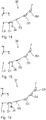
- FIGS. 26 to 28 Different variants of the homogenization of the raw beam 4 by means of the beam-shaping optical system 6 are schematically shown in FIGS FIGS. 26 to 28 shown.
- FIG. 26 schematically the execution of a beam-shaping optical system 6 is shown, by means of which the raw beam 4 is homogenized in two mutually perpendicular directions. This is illustrated by a stepped course of an intensity profile 56 in a first direction and a stepped course of an intensity profile 57 in a second direction.
- the intensity profiles 56, 57 relate to the intensity of the illumination radiation 3 in a cross section of the collection output beam 7 perpendicular to its propagation direction.
- the intensity profile 57 has a stepped course.
- the intensity profile 56 has an inhomogeneous, in particular a non-stepped, in particular a Gaussian shape. In other words, there is a local increase in intensity in a central region of the collection output beam 7, which in the FIG. 27 in the vertical direction.
- the intensity profile 56 in the first direction has a stepped course.
- the intensity profile 57 in the second direction is not homogeneous, in particular non-stepped, in particular Gaussian.
- the intensity is increased in a horizontally extending middle area.
- the intensity profile 56 and / or the intensity profile 57 may, in particular, have a shape which is neither exactly Gaussian nor exactly stepped, but has a Gaussian and a stepped portion.
- the intensity profile 56 and / or the intensity profile 57 can be described in particular as the sum of a Gaussian component and a stepped component.
- An inhomogeneity of the collecting output beam 7 in the second direction can be compensated for by virtue of the fact that the regions of the collecting output beam 7 which are coupled out from the coupling-out optical system 8 into the different individual output beams 9 i are of different size. Due to the size of these areas, it is possible to specify which portion is guided with the illumination radiation 3 in the collective output beam 7 to the individual scanners.
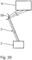
- FIG. 29 an optical element for enlarging the cross section of a beam with illumination radiation 3 is shown.
- a mirror 58 with a convex reflection surface is arranged in the beam path of the illumination radiation 3.
- the mirror 58 is also referred to as a diverging mirror.
- the mirror 58 may have a substantially cylindrical reflection surface, that is convex in a first direction and flat in a second direction perpendicular to the first direction. It can also be convex in both directions.
- the radii of curvature may be identical or different.
- the mirror 58 can thus be used for the targeted enlargement of the cross section of the beam or of the radiation beam with illumination radiation 3.
Landscapes
- Physics & Mathematics (AREA)
- General Physics & Mathematics (AREA)
- Engineering & Computer Science (AREA)
- Computer Networks & Wireless Communication (AREA)
- Health & Medical Sciences (AREA)
- Environmental & Geological Engineering (AREA)
- Epidemiology (AREA)
- Public Health (AREA)
- Plasma & Fusion (AREA)
- Exposure And Positioning Against Photoresist Photosensitive Materials (AREA)
- Exposure Of Semiconductors, Excluding Electron Or Ion Beam Exposure (AREA)
- Lenses (AREA)
Applications Claiming Priority (3)
| Application Number | Priority Date | Filing Date | Title |
|---|---|---|---|
| DE102013223935.1A DE102013223935A1 (de) | 2013-11-22 | 2013-11-22 | Beleuchtungssystem für die EUV-Belichtungslithographie |
| PCT/EP2014/075257 WO2015078776A1 (de) | 2013-11-22 | 2014-11-21 | Beleuchtungssystem für die euv-projektionslithographie |
| EP14802052.2A EP3072015B1 (de) | 2013-11-22 | 2014-11-21 | Beleuchtungssystem für die euv-projektionslithographie |
Related Parent Applications (2)
| Application Number | Title | Priority Date | Filing Date |
|---|---|---|---|
| EP14802052.2A Division-Into EP3072015B1 (de) | 2013-11-22 | 2014-11-21 | Beleuchtungssystem für die euv-projektionslithographie |
| EP14802052.2A Division EP3072015B1 (de) | 2013-11-22 | 2014-11-21 | Beleuchtungssystem für die euv-projektionslithographie |
Publications (1)
| Publication Number | Publication Date |
|---|---|
| EP3467590A1 true EP3467590A1 (de) | 2019-04-10 |
Family
ID=51945892
Family Applications (2)
| Application Number | Title | Priority Date | Filing Date |
|---|---|---|---|
| EP18205398.3A Pending EP3467590A1 (de) | 2013-11-22 | 2014-11-21 | Beleuchtungssystem für die euv-projektionslithographie |
| EP14802052.2A Active EP3072015B1 (de) | 2013-11-22 | 2014-11-21 | Beleuchtungssystem für die euv-projektionslithographie |
Family Applications After (1)
| Application Number | Title | Priority Date | Filing Date |
|---|---|---|---|
| EP14802052.2A Active EP3072015B1 (de) | 2013-11-22 | 2014-11-21 | Beleuchtungssystem für die euv-projektionslithographie |
Country Status (7)
Families Citing this family (18)
| Publication number | Priority date | Publication date | Assignee | Title |
|---|---|---|---|---|
| DE102013223935A1 (de) | 2013-11-22 | 2015-05-28 | Carl Zeiss Smt Gmbh | Beleuchtungssystem für die EUV-Belichtungslithographie |
| DE102014221173A1 (de) | 2014-10-17 | 2016-04-21 | Carl Zeiss Smt Gmbh | Strahlungsquellenmodul |
| DE102014226920A1 (de) | 2014-12-23 | 2016-06-23 | Carl Zeiss Smt Gmbh | Optische Komponente |
| DE102014226921A1 (de) | 2014-12-23 | 2016-06-23 | Carl Zeiss Smt Gmbh | Strahlungsquellenmodul |
| TWI701517B (zh) | 2014-12-23 | 2020-08-11 | 德商卡爾蔡司Smt有限公司 | 光學構件 |
| DE102014226918A1 (de) | 2014-12-23 | 2016-06-23 | Carl Zeiss Smt Gmbh | Optische Komponente |
| DE102015212878A1 (de) | 2015-07-09 | 2017-01-12 | Carl Zeiss Smt Gmbh | Strahlführungsvorrichtung |
| DE102015215216A1 (de) * | 2015-08-10 | 2017-02-16 | Carl Zeiss Smt Gmbh | Optisches System |
| JP6762355B2 (ja) | 2015-09-03 | 2020-09-30 | エーエスエムエル ネザーランズ ビー.ブイ. | ビーム分割装置 |
| DE102015012053A1 (de) | 2015-09-14 | 2017-03-16 | M+W Group GmbH | Fertigungsanlage zur Herstellung von integrierten Schaltkreisen aus Halbleiter-Wafern sowie Waffelelement für eine Fertigungsanlage |
| DE102015220955A1 (de) | 2015-10-27 | 2015-12-17 | Carl Zeiss Smt Gmbh | Optisches Bauelement |
| DE102016217426A1 (de) | 2016-09-13 | 2017-08-24 | Carl Zeiss Smt Gmbh | Strahlteiler |
| DE102017205548A1 (de) * | 2017-03-31 | 2018-10-04 | Carl Zeiss Smt Gmbh | Optische Baugruppe zum Führen eines Ausgabestrahls eines Freie-Elektronen-Lasers |
| CN107166180A (zh) * | 2017-06-14 | 2017-09-15 | 杨毅 | 灯具 |
| DE102017210190A1 (de) | 2017-06-19 | 2018-03-15 | Carl Zeiss Smt Gmbh | Optisches Element |
| KR102374206B1 (ko) | 2017-12-05 | 2022-03-14 | 삼성전자주식회사 | 반도체 장치 제조 방법 |
| DE102018212224A1 (de) | 2018-07-23 | 2020-01-23 | Carl Zeiss Smt Gmbh | Vorrichtung zur Rückkopplung von emittierter Strahlung in eine Laserquelle |
| EP3627226A1 (en) * | 2018-09-20 | 2020-03-25 | ASML Netherlands B.V. | Optical system, metrology apparatus and associated method |
Citations (3)
| Publication number | Priority date | Publication date | Assignee | Title |
|---|---|---|---|---|
| EP1225481A2 (de) * | 2001-01-23 | 2002-07-24 | Carl Zeiss Semiconductor Manufacturing Technologies Ag | Kollektor für Beleuchtungssysteme mit einer Wellenlänge 193 nm |
| US20050243297A1 (en) * | 2004-05-03 | 2005-11-03 | Asml Netherlands B.V. | Lithographic apparatus and device manufacturing method |
| DE102008014832A1 (de) * | 2007-04-19 | 2008-10-23 | Carl Zeiss Smt Ag | Projektionsbelichtungsanlage für die Mikrolithographie |
Family Cites Families (36)
| Publication number | Priority date | Publication date | Assignee | Title |
|---|---|---|---|---|
| US2766385A (en) * | 1952-09-11 | 1956-10-09 | Herrnring Gunther | Optical image-forming plural reflecting mirror systems |
| JPH05114546A (ja) * | 1991-10-22 | 1993-05-07 | Toshiba Corp | X線露光装置 |
| US5268951A (en) * | 1992-12-22 | 1993-12-07 | International Business Machines Corporation | X-ray beam scanning method for producing low distortion or constant distortion in x-ray proximity printing |
| JP3499592B2 (ja) * | 1994-01-31 | 2004-02-23 | 株式会社ルネサステクノロジ | 投影露光装置及びパターン転写方法 |
| ATE169769T1 (de) * | 1994-05-11 | 1998-08-15 | Univ Colorado | Roentgenstrahlungsoptik mit streifendem lichteinfall und sphaerischen spiegeln |
| JP3167095B2 (ja) * | 1995-07-04 | 2001-05-14 | キヤノン株式会社 | 照明装置とこれを有する露光装置や顕微鏡装置、ならびにデバイス生産方法 |
| JP3284045B2 (ja) | 1996-04-30 | 2002-05-20 | キヤノン株式会社 | X線光学装置およびデバイス製造方法 |
| US6438199B1 (en) | 1998-05-05 | 2002-08-20 | Carl-Zeiss-Stiftung | Illumination system particularly for microlithography |
| DE10053587A1 (de) | 2000-10-27 | 2002-05-02 | Zeiss Carl | Beleuchtungssystem mit variabler Einstellung der Ausleuchtung |
| EP0955641B1 (de) * | 1998-05-05 | 2004-04-28 | Carl Zeiss | Beleuchtungssystem insbesondere für die EUV-Lithographie |
| DE19935404A1 (de) | 1999-07-30 | 2001-02-01 | Zeiss Carl Fa | Beleuchtungssystem mit mehreren Lichtquellen |
| US6859515B2 (en) | 1998-05-05 | 2005-02-22 | Carl-Zeiss-Stiftung Trading | Illumination system, particularly for EUV lithography |
| TWI243287B (en) * | 1999-03-12 | 2005-11-11 | Asml Netherlands Bv | Lithographic projection apparatus and device manufacturing method using the same |
| JP2003506881A (ja) | 1999-07-30 | 2003-02-18 | カール ツァイス シュティフトゥング トレイディング アズ カール ツァイス | Euv照明光学系の射出瞳における照明分布の制御 |
| DE10001291A1 (de) | 2000-01-14 | 2001-07-19 | Zeiss Carl | Adaptronischer Spiegel |
| DE60217771T3 (de) * | 2001-07-27 | 2012-02-09 | Canon K.K. | Belichtungssystem, Projektionsbelichtungsapparat und Verfahren zur Herstellung eines Artikels |
| US6798494B2 (en) | 2001-08-30 | 2004-09-28 | Euv Llc | Apparatus for generating partially coherent radiation |
| US7020006B2 (en) * | 2002-08-02 | 2006-03-28 | Unity Semiconductor Corporation | Discharge of conductive array lines in fast memory |
| US7217940B2 (en) * | 2003-04-08 | 2007-05-15 | Cymer, Inc. | Collector for EUV light source |
| EP1496521A1 (en) | 2003-07-09 | 2005-01-12 | ASML Netherlands B.V. | Mirror and lithographic apparatus with mirror |
| WO2005026843A2 (en) | 2003-09-12 | 2005-03-24 | Carl Zeiss Smt Ag | Illumination system for a microlithography projection exposure installation |
| DE10343333A1 (de) * | 2003-09-12 | 2005-04-14 | Carl Zeiss Smt Ag | Beleuchtungssystem für eine Mikrolithographie-Projektionsbelichtungsanlage |
| DE10358225B3 (de) | 2003-12-12 | 2005-06-30 | Forschungszentrum Karlsruhe Gmbh | Undulator und Verfahren zu dessen Betrieb |
| JP4551666B2 (ja) * | 2004-02-19 | 2010-09-29 | キヤノン株式会社 | 照明装置及び露光装置 |
| US20070152171A1 (en) | 2005-12-30 | 2007-07-05 | Michael Goldstein | Free electron laser |
| US8766212B2 (en) * | 2006-07-19 | 2014-07-01 | Asml Netherlands B.V. | Correction of spatial instability of an EUV source by laser beam steering |
| DE102006034755A1 (de) | 2006-07-24 | 2008-01-31 | Carl Zeiss Smt Ag | Optische Vorrichtung sowie Verfahren zur Korrektur bzw. Verbesserung des Abbildungsverhaltens einer optischen Vorrichtung |
| EP1882984B1 (en) * | 2006-07-28 | 2011-10-12 | Media Lario s.r.l. | Multi-reflection optical systems and their fabrication |
| DE102008000967B4 (de) | 2008-04-03 | 2015-04-09 | Carl Zeiss Smt Gmbh | Projektionsbelichtungsanlage für die EUV-Mikrolithographie |
| US8390788B2 (en) * | 2008-07-11 | 2013-03-05 | Asml Netherlands B.V. | Spectral purity filters for use in a lithographic apparatus |
| DE102009025655A1 (de) | 2008-08-27 | 2010-03-04 | Carl Zeiss Smt Ag | Optische Komponente zum Einsatz in einem Beleuchtungssystem für eine Projektionsbelichtungsanlage der EUV-Mikrolithographie |
| DE102009045135A1 (de) | 2009-09-30 | 2011-03-31 | Carl Zeiss Smt Gmbh | Beleuchtungsoptik für die Mikrolithographie |
| EP2513697B1 (en) * | 2009-12-14 | 2019-08-07 | Carl Zeiss SMT GmbH | Imaging optics |
| EP2533078B1 (en) * | 2011-06-09 | 2014-02-12 | ASML Netherlands BV | Radiation source and lithographic apparatus |
| TWI711896B (zh) * | 2013-09-25 | 2020-12-01 | 荷蘭商Asml荷蘭公司 | 光學元件、輻射系統及微影系統 |
| DE102013223935A1 (de) | 2013-11-22 | 2015-05-28 | Carl Zeiss Smt Gmbh | Beleuchtungssystem für die EUV-Belichtungslithographie |
-
2013
- 2013-11-22 DE DE102013223935.1A patent/DE102013223935A1/de not_active Ceased
-
2014
- 2014-11-21 EP EP18205398.3A patent/EP3467590A1/de active Pending
- 2014-11-21 WO PCT/EP2014/075257 patent/WO2015078776A1/de active Application Filing
- 2014-11-21 KR KR1020217009708A patent/KR102380615B1/ko active Active
- 2014-11-21 CN CN201480063956.4A patent/CN105765460B/zh active Active
- 2014-11-21 JP JP2016533541A patent/JP6623156B2/ja active Active
- 2014-11-21 CN CN201811466330.4A patent/CN110068990B/zh active Active
- 2014-11-21 KR KR1020167016530A patent/KR102413481B1/ko active Active
- 2014-11-21 EP EP14802052.2A patent/EP3072015B1/de active Active
-
2016
- 2016-05-12 US US15/152,670 patent/US9958783B2/en active Active
-
2018
- 2018-04-05 US US15/945,879 patent/US10310381B2/en active Active
Patent Citations (3)
| Publication number | Priority date | Publication date | Assignee | Title |
|---|---|---|---|---|
| EP1225481A2 (de) * | 2001-01-23 | 2002-07-24 | Carl Zeiss Semiconductor Manufacturing Technologies Ag | Kollektor für Beleuchtungssysteme mit einer Wellenlänge 193 nm |
| US20050243297A1 (en) * | 2004-05-03 | 2005-11-03 | Asml Netherlands B.V. | Lithographic apparatus and device manufacturing method |
| DE102008014832A1 (de) * | 2007-04-19 | 2008-10-23 | Carl Zeiss Smt Ag | Projektionsbelichtungsanlage für die Mikrolithographie |
Also Published As
| Publication number | Publication date |
|---|---|
| EP3072015B1 (de) | 2019-01-02 |
| JP6623156B2 (ja) | 2019-12-18 |
| JP2016537681A (ja) | 2016-12-01 |
| KR20160088421A (ko) | 2016-07-25 |
| KR102413481B1 (ko) | 2022-06-27 |
| US20180224750A1 (en) | 2018-08-09 |
| EP3072015A1 (de) | 2016-09-28 |
| KR20210039000A (ko) | 2021-04-08 |
| KR102380615B1 (ko) | 2022-03-30 |
| US9958783B2 (en) | 2018-05-01 |
| US20160252823A1 (en) | 2016-09-01 |
| CN105765460B (zh) | 2018-12-28 |
| CN110068990A (zh) | 2019-07-30 |
| US10310381B2 (en) | 2019-06-04 |
| CN110068990B (zh) | 2021-12-28 |
| CN105765460A (zh) | 2016-07-13 |
| DE102013223935A1 (de) | 2015-05-28 |
| WO2015078776A1 (de) | 2015-06-04 |
Similar Documents
| Publication | Publication Date | Title |
|---|---|---|
| EP3072015B1 (de) | Beleuchtungssystem für die euv-projektionslithographie | |
| EP1067437B1 (de) | Beleuchtungssystem mit anamorphotischen Komponenten zur Erhöhung des Bildfeldaspektverhältnisses | |
| EP1200879B1 (de) | Steuerung der Beleuchtungsverteilung in der Austrittspupille eines EUV-Beleuchtungssystems | |
| DE102012214063A1 (de) | Beleuchtungssystem für eine Projektionsbelichtungsanlage für die EUV-Projektionslithographie | |
| EP1180726B1 (de) | Beleuchtungssystem für die Mikrolithographie | |
| EP3860798B1 (de) | Laserbearbeitungssystem | |
| DE102020108648A1 (de) | Optische Anordnung und Lasersystem | |
| DE102008027229B4 (de) | Vorrichtung zur Strahlformung | |
| WO2021197923A1 (de) | Optische anordnung und lasersystem | |
| EP1239330A1 (de) | Steuerung der Beleuchtungsverteilung in der Austrittspupille eines EUV-Beleuchtungssystems | |
| DE102010039965B4 (de) | EUV-Kollektor | |
| DE102011076658A1 (de) | Beleuchtungsoptik für die EUV-Projektionslithographie | |
| EP3039485A1 (de) | Mikrospiegel-array | |
| DE102016202736A1 (de) | Beleuchtungsoptik für eine Projektionsbelichtungsanlage | |
| DE102014226917A1 (de) | Beleuchtungssystem für die EUV-Projektionslithographie | |
| DE102014217620A1 (de) | Beleuchtungsoptik für eine Projektionsbelichtungsanlage | |
| DE102014215088A1 (de) | Beleuchtungseinrichtung für ein Projektionsbelichtungssystem | |
| WO2017025376A1 (de) | Optisches system | |
| DE102016211732A1 (de) | Optisches Bauelement | |
| EP3827488B1 (de) | Strahlungsquelle und vorrichtung zur rückkopplung von emittierter strahlung in eine laserquelle | |
| DE102014221173A1 (de) | Strahlungsquellenmodul | |
| DE102017200658A1 (de) | Beleuchtungsoptik für eine Projektionsbelichtungsanlage | |
| DE102016217426A1 (de) | Strahlteiler | |
| WO2019096604A1 (de) | Beleuchtungsintensitäts-korrekturvorrichtung zur vorgabe einer beleuchtungsintensität über ein beleuchtungsfeld einer lithographischen projektionsbelichtungsanlage | |
| WO2017005912A2 (de) | Verfahren zur steuerung einer strahlführungsvorrichtung und strahlführungsvorrichtung |
Legal Events
| Date | Code | Title | Description |
|---|---|---|---|
| PUAI | Public reference made under article 153(3) epc to a published international application that has entered the european phase |
Free format text: ORIGINAL CODE: 0009012 |
|
| STAA | Information on the status of an ep patent application or granted ep patent |
Free format text: STATUS: THE APPLICATION HAS BEEN PUBLISHED |
|
| AC | Divisional application: reference to earlier application |
Ref document number: 3072015 Country of ref document: EP Kind code of ref document: P |
|
| AK | Designated contracting states |
Kind code of ref document: A1 Designated state(s): AL AT BE BG CH CY CZ DE DK EE ES FI FR GB GR HR HU IE IS IT LI LT LU LV MC MK MT NL NO PL PT RO RS SE SI SK SM TR |
|
| STAA | Information on the status of an ep patent application or granted ep patent |
Free format text: STATUS: REQUEST FOR EXAMINATION WAS MADE |
|
| 17P | Request for examination filed |
Effective date: 20191010 |
|
| RBV | Designated contracting states (corrected) |
Designated state(s): AL AT BE BG CH CY CZ DE DK EE ES FI FR GB GR HR HU IE IS IT LI LT LU LV MC MK MT NL NO PL PT RO RS SE SI SK SM TR |
|
| STAA | Information on the status of an ep patent application or granted ep patent |
Free format text: STATUS: REQUEST FOR EXAMINATION WAS MADE |
|
| R17P | Request for examination filed (corrected) |
Effective date: 20191010 |
|
| GRAP | Despatch of communication of intention to grant a patent |
Free format text: ORIGINAL CODE: EPIDOSNIGR1 |
|
| STAA | Information on the status of an ep patent application or granted ep patent |
Free format text: STATUS: GRANT OF PATENT IS INTENDED |
|
| INTG | Intention to grant announced |
Effective date: 20250728 |