EP3467590A1 - Beleuchtungssystem für die euv-projektionslithographie - Google Patents
Beleuchtungssystem für die euv-projektionslithographie Download PDFInfo
- Publication number
- EP3467590A1 EP3467590A1 EP18205398.3A EP18205398A EP3467590A1 EP 3467590 A1 EP3467590 A1 EP 3467590A1 EP 18205398 A EP18205398 A EP 18205398A EP 3467590 A1 EP3467590 A1 EP 3467590A1
- Authority
- EP
- European Patent Office
- Prior art keywords
- euv
- mirror
- optics
- mirrors
- optical system
- Prior art date
- Legal status (The legal status is an assumption and is not a legal conclusion. Google has not performed a legal analysis and makes no representation as to the accuracy of the status listed.)
- Pending
Links
Images


Classifications
-
- G—PHYSICS
- G03—PHOTOGRAPHY; CINEMATOGRAPHY; ANALOGOUS TECHNIQUES USING WAVES OTHER THAN OPTICAL WAVES; ELECTROGRAPHY; HOLOGRAPHY
- G03F—PHOTOMECHANICAL PRODUCTION OF TEXTURED OR PATTERNED SURFACES, e.g. FOR PRINTING, FOR PROCESSING OF SEMICONDUCTOR DEVICES; MATERIALS THEREFOR; ORIGINALS THEREFOR; APPARATUS SPECIALLY ADAPTED THEREFOR
- G03F7/00—Photomechanical, e.g. photolithographic, production of textured or patterned surfaces, e.g. printing surfaces; Materials therefor, e.g. comprising photoresists; Apparatus specially adapted therefor
- G03F7/20—Exposure; Apparatus therefor
- G03F7/2002—Exposure; Apparatus therefor with visible light or UV light, through an original having an opaque pattern on a transparent support, e.g. film printing, projection printing; by reflection of visible or UV light from an original such as a printed image
- G03F7/2004—Exposure; Apparatus therefor with visible light or UV light, through an original having an opaque pattern on a transparent support, e.g. film printing, projection printing; by reflection of visible or UV light from an original such as a printed image characterised by the use of a particular light source, e.g. fluorescent lamps or deep UV light
- G03F7/2006—Exposure; Apparatus therefor with visible light or UV light, through an original having an opaque pattern on a transparent support, e.g. film printing, projection printing; by reflection of visible or UV light from an original such as a printed image characterised by the use of a particular light source, e.g. fluorescent lamps or deep UV light using coherent light; using polarised light
-
- G—PHYSICS
- G03—PHOTOGRAPHY; CINEMATOGRAPHY; ANALOGOUS TECHNIQUES USING WAVES OTHER THAN OPTICAL WAVES; ELECTROGRAPHY; HOLOGRAPHY
- G03F—PHOTOMECHANICAL PRODUCTION OF TEXTURED OR PATTERNED SURFACES, e.g. FOR PRINTING, FOR PROCESSING OF SEMICONDUCTOR DEVICES; MATERIALS THEREFOR; ORIGINALS THEREFOR; APPARATUS SPECIALLY ADAPTED THEREFOR
- G03F7/00—Photomechanical, e.g. photolithographic, production of textured or patterned surfaces, e.g. printing surfaces; Materials therefor, e.g. comprising photoresists; Apparatus specially adapted therefor
- G03F7/70—Microphotolithographic exposure; Apparatus therefor
- G03F7/70058—Mask illumination systems
- G03F7/7015—Details of optical elements
- G03F7/70183—Zoom systems for adjusting beam diameter
-
- G—PHYSICS
- G03—PHOTOGRAPHY; CINEMATOGRAPHY; ANALOGOUS TECHNIQUES USING WAVES OTHER THAN OPTICAL WAVES; ELECTROGRAPHY; HOLOGRAPHY
- G03F—PHOTOMECHANICAL PRODUCTION OF TEXTURED OR PATTERNED SURFACES, e.g. FOR PRINTING, FOR PROCESSING OF SEMICONDUCTOR DEVICES; MATERIALS THEREFOR; ORIGINALS THEREFOR; APPARATUS SPECIALLY ADAPTED THEREFOR
- G03F7/00—Photomechanical, e.g. photolithographic, production of textured or patterned surfaces, e.g. printing surfaces; Materials therefor, e.g. comprising photoresists; Apparatus specially adapted therefor
- G03F7/70—Microphotolithographic exposure; Apparatus therefor
- G03F7/70008—Production of exposure light, i.e. light sources
- G03F7/70033—Production of exposure light, i.e. light sources by plasma extreme ultraviolet [EUV] sources
-
- G—PHYSICS
- G03—PHOTOGRAPHY; CINEMATOGRAPHY; ANALOGOUS TECHNIQUES USING WAVES OTHER THAN OPTICAL WAVES; ELECTROGRAPHY; HOLOGRAPHY
- G03F—PHOTOMECHANICAL PRODUCTION OF TEXTURED OR PATTERNED SURFACES, e.g. FOR PRINTING, FOR PROCESSING OF SEMICONDUCTOR DEVICES; MATERIALS THEREFOR; ORIGINALS THEREFOR; APPARATUS SPECIALLY ADAPTED THEREFOR
- G03F7/00—Photomechanical, e.g. photolithographic, production of textured or patterned surfaces, e.g. printing surfaces; Materials therefor, e.g. comprising photoresists; Apparatus specially adapted therefor
- G03F7/70—Microphotolithographic exposure; Apparatus therefor
- G03F7/70058—Mask illumination systems
- G03F7/70191—Optical correction elements, filters or phase plates for controlling intensity, wavelength, polarisation, phase or the like
-
- G—PHYSICS
- G03—PHOTOGRAPHY; CINEMATOGRAPHY; ANALOGOUS TECHNIQUES USING WAVES OTHER THAN OPTICAL WAVES; ELECTROGRAPHY; HOLOGRAPHY
- G03F—PHOTOMECHANICAL PRODUCTION OF TEXTURED OR PATTERNED SURFACES, e.g. FOR PRINTING, FOR PROCESSING OF SEMICONDUCTOR DEVICES; MATERIALS THEREFOR; ORIGINALS THEREFOR; APPARATUS SPECIALLY ADAPTED THEREFOR
- G03F7/00—Photomechanical, e.g. photolithographic, production of textured or patterned surfaces, e.g. printing surfaces; Materials therefor, e.g. comprising photoresists; Apparatus specially adapted therefor
- G03F7/70—Microphotolithographic exposure; Apparatus therefor
- G03F7/70058—Mask illumination systems
- G03F7/702—Reflective illumination, i.e. reflective optical elements other than folding mirrors, e.g. extreme ultraviolet [EUV] illumination systems
-
- G—PHYSICS
- G03—PHOTOGRAPHY; CINEMATOGRAPHY; ANALOGOUS TECHNIQUES USING WAVES OTHER THAN OPTICAL WAVES; ELECTROGRAPHY; HOLOGRAPHY
- G03F—PHOTOMECHANICAL PRODUCTION OF TEXTURED OR PATTERNED SURFACES, e.g. FOR PRINTING, FOR PROCESSING OF SEMICONDUCTOR DEVICES; MATERIALS THEREFOR; ORIGINALS THEREFOR; APPARATUS SPECIALLY ADAPTED THEREFOR
- G03F7/00—Photomechanical, e.g. photolithographic, production of textured or patterned surfaces, e.g. printing surfaces; Materials therefor, e.g. comprising photoresists; Apparatus specially adapted therefor
- G03F7/70—Microphotolithographic exposure; Apparatus therefor
- G03F7/708—Construction of apparatus, e.g. environment aspects, hygiene aspects or materials
- G03F7/70991—Connection with other apparatus, e.g. multiple exposure stations, particular arrangement of exposure apparatus and pre-exposure and/or post-exposure apparatus; Shared apparatus, e.g. having shared radiation source, shared mask or workpiece stage, shared base-plate; Utilities, e.g. cable, pipe or wireless arrangements for data, power, fluids or vacuum
-
- G—PHYSICS
- G03—PHOTOGRAPHY; CINEMATOGRAPHY; ANALOGOUS TECHNIQUES USING WAVES OTHER THAN OPTICAL WAVES; ELECTROGRAPHY; HOLOGRAPHY
- G03F—PHOTOMECHANICAL PRODUCTION OF TEXTURED OR PATTERNED SURFACES, e.g. FOR PRINTING, FOR PROCESSING OF SEMICONDUCTOR DEVICES; MATERIALS THEREFOR; ORIGINALS THEREFOR; APPARATUS SPECIALLY ADAPTED THEREFOR
- G03F7/00—Photomechanical, e.g. photolithographic, production of textured or patterned surfaces, e.g. printing surfaces; Materials therefor, e.g. comprising photoresists; Apparatus specially adapted therefor
- G03F7/70—Microphotolithographic exposure; Apparatus therefor
- G03F7/70058—Mask illumination systems
- G03F7/70091—Illumination settings, i.e. intensity distribution in the pupil plane or angular distribution in the field plane; On-axis or off-axis settings, e.g. annular, dipole or quadrupole settings; Partial coherence control, i.e. sigma or numerical aperture [NA]
- G03F7/70116—Off-axis setting using a programmable means, e.g. liquid crystal display [LCD], digital micromirror device [DMD] or pupil facets
Definitions
- the invention relates to a beam guiding optical system for an illumination system for EUV projection lithography.
- the invention also relates to an illumination system for EUV projection lithography and a projection exposure apparatus for EUV lithography.
- the invention relates to a method for producing a structured component and to a structured component produced by this method.
- a projection exposure apparatus with a lighting system is known from the US 2011/0 014 799 A1 , from the WO 2009/121 438 A1 , from the US 2009/0174 876 A1 , from the US Pat. No. 6,438,199 B1 and the US 6,658,084 B2 .
- An EUV light source is known from the DE 103 58 225 B3 and the US 6,859,515 B .
- Other components for the EUV projection lithography are known from the US 2003/0002022 A1 , the DE 10 2009 025 655 A1 , the US 6,700,952 and the US 2004/0140440 A
- Further references, from which an EUV light source is known can be found in the WO 2009/121 438 A1 , EUV illumination optics are still known from the US 2003/0043359 A1 and the US 5,896,438 ,
- a beam guiding optical system according to claim 1 makes it possible to pass the EUV radiation through a comparatively small passage opening through a diaphragm or a wall. This allows a desired separation between different chambers in which the EUV radiation is guided.
- assemblies of projection exposure systems can be used which are tuned to an intermediate focus of the EUV illumination light with a predetermined numerical aperture.
- a focusing assembly may be implemented in the manner of a Type I, Type II or Type III Wolter mirror array.
- the at least two mirrors of the focusing module can be arranged sequentially in the beam path of the EUV single output beam.
- the focusing assembly may be configured so that a mounting space of the focusing assembly along a beam path of the EUV single output beam is about twice as large as a large half-axis of an ellipsoidal mirror of the focusing assembly.
- the focusing assembly may be configured such that an installation space of the focusing assembly along a beam path of the EUV single output beam is about fifty times as large as a diameter of the EUV single output beam entering the focusing assembly.
- the focusing assembly may be designed such that, for a ratio b / a from a minor semiaxis b of the ellipsoidal mirror and a major semiaxis a of the ellipsoidal mirror, 0.7NA ⁇ b / a ⁇ 0.9NA, where NA denotes the numerical aperture in the intermediate focus of the focusing assembly.
- the focusing assembly may be configured to have at least one paraboloidal mirror, wherein for a ratio a / f from a major semiaxis a of the ellipsoidal mirror and a focal length f of the paraboloidal mirror: a / f> 50.
- the focusing assembly may be designed so that a minimum deflection angle experienced by a marginal beam of the EUV single output beam through the focusing assembly is not greater than 5 °.
- the beam guidance of EUV light or EUV radiation provided by a synchrotron radiation-based light source requires a specific processing due to the properties of the EUV raw beam emitted by such a light source. This processing is ensured by the beam shaping optics according to the invention, the coupling optics and the beam guiding optics as well as by the individual beam-guiding components, namely the deflection optics and the focusing assembly.
- the synchrotron radiation-based light source may be a free-electron laser (FEL), an undulator, a wiggler or an x-ray laser.
- the synchrotron radiation-based light source may have an optical conductivity less than 0.1 mm 2 or an even smaller optical conductivity.
- the optics according to the invention can generally work with the emission of a light source having such a small optical conductivity, regardless of whether it is a synchrotron radiation-based light source.
- the beam shaping optics provides for a preforming of a collective output beam from the raw beam in preparation for a subsequent decoupling via the coupling-out optics into single output beams.
- the latter are guided by the beam guiding optics to the respective object field.
- the coupling-out optics and the subsequent beam-guiding optics can be used to ensure a variable intensity distribution for the components of the radiation power in the various EUV individual output beams. In this way, an adaptation to the number of projection exposure systems to be supplied as well as an adaptation to the light output required by the respective projection exposure apparatus can take place. Also, different requirements that exist for the production of specific structures to the respective required light output, can then be met by appropriate adjustment of the lighting system.
- a deflection optics comprises at least four deflection mirrors for grazing incidence.
- the grazing incidence mirrors are designed for an angle of incidence greater than 60 °.
- the angle of incidence can be even greater.
- At least one of the glancing mirrors for grazing incidence can be designed as a convex cylindrical mirror. At least one of the deflecting mirrors for grazing incidence may be considered concave Cylinder mirror be executed. Designs of the deflection optics can have a larger number of concave cylindrical mirrors than convex cylindrical mirrors.
- An EUV beam incident in parallel in the deflection optics in particular an EUV single output beam, may have a divergence of less than 1 mrad after leaving the deflection optics.
- Such a design of the deflection optics makes it possible to guide the EUV beam over long distances.
- an aspect ratio contribution of the beam guidance optics generated by the deflection optics can be adapted to a default value.
- an expansion factor for the aspect ratio between a value of 4 and a value of 5 or between a value of 1.5 and a value of 2 can be varied in particular continuously.
- At least one of the deflection mirrors for grazing incidence of the deflection optics can be designed with a driven variable radius of curvature. This makes it possible to achieve a further adaptation of the optical effect of the deflection optics to a default value.
- the group planes of incidence may be perpendicular to each other.
- Mirror groups of the beam shaping optics can have two mirrors, three mirrors or even more mirrors. By using multiple mirror groups with different group incident planes, the EUV radiation in two transverse dimensions can be independently influenced to produce a desired aspect ratio.
- the mirror groups can be designed in the manner of Galilei telescopes.
- the mirrors of the beam shaping optics can be used as z. B. be executed convex or concave cylindrical mirror.
- the grazing incidence mirrors are designed for an angle of incidence greater than 60 °.
- the angle of incidence can be even greater.
- An arrangement in which all the mirrors of one of the mirror groups in the beam path after a first mirror of another mirror group and before a last mirror of this further mirror group provides the ability to provide a large distance between those mirrors of the same mirror array which, for example, must provide a large expansion factor to produce a desired aspect ratio.
- Incidence angles of the EUV radiation which are the same on all mirrors of a mirror group, allow a transmission optimization for the EUV radiation when passing through the beam shaping optics.
- Incidence angles that are different on at least two mirrors of one of the mirror sets increase flexibility in the design of the beamforming optics and, for example, allow a grazing incidence to conform to a given beam diameter of the incident EUV beam such that a mirror size remains within predetermined dimensions.
- a design of the beam shaping optics in which projected onto the group plane of incidence of the mirror group with different angles of incidence of the generated EUV collective output beam in the same direction as the EUV raw beam, which is incident in the beam shaping optics, allows, for example, both in the Beam shaping optics incident as well as the beam emerging from the beam shaping optics to lead horizontally.
- Divergence of the EUV collective output beam may be less than a half divergence of the EUV raw beam.
- An appropriate design of the beam shaping optics makes it possible to guide the EUV collective output beam over long distances.
- At least one mirror of the beam shaping optics may have a deviation of at least 5 ⁇ m from a best fit conic. At least one mirror of the beam-shaping optical system can be designed as a freeform surface. Corresponding mirror designs of the beam-shaping optical system increase the degrees of freedom in order to adapt an optical effect of the beam-shaping optical system to default values.
- the object is further achieved by a lighting system with a beam guiding optical system according to the preceding description.
- the advantages result from those described for the respective components.
- An illumination system with a beam-shaping optical system and a coupling-out optical system according to claim 10 makes it possible to provide a plurality of EUV single output beams having a predetermined aspect ratio of an EUV beam diameter.
- the aspect ratio contributions provided by the beam-shaping optical system on the one hand and by the coupling-out optical system and the subsequent beam-guiding optical system on the other hand can still be multiplied by a desired target aspect ratio, for example with the aspect ratio of an object field to be illuminated.
- Generating a desired aspect ratio contribution of the multiple single output jets of 1: 1, starting from the raw beam, is distributed on the one hand to producing an aspect ratio contribution not equal to 1 over the beamforming optics and, after splitting the collection output beam into the plurality of single output jets Generation of a corresponding aspect ratio contribution by the coupling-out optics and the beam guiding optics.
- This allows for moderate aspect ratio changes along the path of the EUV illumination light from the light source to the object field, which must be brought about by the various optical assemblies passing through the EUV beam.
- another aspect ratio contribution can be generated with the beam-shaping optical system, for example an aspect ratio contribution of 1: N for N EUV single output beams.
- a subsequent coupling-out optics must then split the EUV collective output beam generated in this way, but then does not require its own aspect-influencing effect for specifying the EUV single output beams with the aspect ratio contribution of 1: 1 each.
- the light source of the illumination system may be a free electron laser (FEL), an undulator, a wiggler, or an x-ray laser.
- FEL free electron laser
- the light source of the illumination system may be a free electron laser (FEL), an undulator, a wiggler, or an x-ray laser.
- the EUV collective output beam can have an intensity distribution which deviates from a homogeneous intensity by less than 10% in each point of the useful cross section.
- a corresponding homogeneity can have a respective EUV single output beam after the deflection optics.
- All mirrors of the lighting system can carry highly reflective coatings.
- the beam-shaping optics, the deflection optics and the focusing assembly are assemblies that are also essential to the invention, ie without the other components of the illumination system, essential to the invention.
- a microlithography projection exposure apparatus 1 is part of a system of several projection exposure apparatuses, of which in the Fig. 1 one of the projection exposure systems 1 is shown.
- the projection exposure apparatus 1 is used to produce a microstructured or nanostructured electronic semiconductor component.
- a common light or radiation source 2 for all projection exposure systems of the system emits EUV radiation in the wavelength range, for example, between 2 nm and 30 nm, in particular between 2 nm and 15 nm.
- the light source 2 is designed as a free-electron laser (FEL). It is a synchrotron radiation source or a synchrotron radiation-based light source, which generates coherent radiation with very high brilliance.
- FEL free-electron laser
- a light source 2 which can be used, for example, is described in Uwe Schindler "A superconducting undulator with electrically switchable helicity", Klasclin Düsseldorf in the Helmholtz Association, scientific reports, FZKA 6997, August 2004, in the US 2007/0152171 A1 and in the DE 103 58 225 B3 ,
- the light source 2 has an original light conductance in a raw beam which is smaller than 0.1 mm 2 .
- the optical conductivity is the smallest volume of a phase space that contains 90% of the light energy of an emission from a light source.
- Corresponding definitions of the optical conductivity can be found in the EP 1 072 957 A2 and the US 6,198,793 B1 in which it is stated that the optical conductivity is obtained by multiplying the illumination data x, y and NA 2 , where x and y are the field dimensions spanning an illuminated illumination field and NA is the numerical aperture of the field illumination. Even smaller light conductance values of the light source than 0.1 mm 2 are possible, for example, an optical conductivity of less than 0.01 mm 2 .
- the EUV light source 2 has an electron beam supply device for generating an electron beam and an EUV generation device. The latter is supplied with the electron beam via the electron beam supply device.
- the EUV generation device is designed as an undulator.
- the undulator may optionally include displacement-adjustable undulator magnets.
- the undulator may have electromagnets.
- a wiggler can also be provided at the light source 2.
- the light source 2 has an average power of 2.5 kW.
- the pulse frequency of the light source 2 is 30 MHz.
- Each individual radiation pulse then carries an energy of 83 ⁇ J. With a radiation pulse length of 100 fs, this corresponds to a radiation pulse power of 833 MW.
- a repetition rate of the light source 2 can be in the kilohertz range, for example at 100 kHz, or in the lower megahertz range, for example at 3 MHz, in the middle megahertz range, for example at 30 MHz, in the upper megahertz range, for example at 300 MHz, or else in the gigahertz range, for example at 1 , 3 GHz, lie.
- a Cartesian xyz coordinate system is used below.
- the x-coordinate regularly tightens a bundle cross-section of the EUV illumination and imaging light 3 with the y-coordinate in these representations. Accordingly, the z-direction is regularly in the beam direction of the illumination and imaging light 3.
- the x-direction extends for example in the Fig. 2 and 12 vertically, ie perpendicular to building levels in which the system of projection exposure systems 1 is housed.
- the coordinate system of Fig. 4 to 11 this is rotated by 90 ° about the z-axis.
- Fig. 1 shows very schematically main components of one of the projection exposure systems 1 of the system.
- the light source 2 mimics lighting and imaging light 3 in the form of a first EUV raw beam.
- Fig. 3 shows very schematically on the left a cross section through the EUV raw beam. 4 with an x / y aspect ratio of 1: 1.
- the raw beam 4 is present as a bundle with a Gaussian intensity profile, ie as a round in cross-section bundle, which in the Fig. 3 is indicated by a dashed boundary line 5.
- the EUV raw beam 4 has a very small divergence.
- a beam shaping optics 6 (cf. Fig. 1 ) is used to generate a EUV collective output beam 7 from the EUV raw beam 4. This is in the Fig. 1 very strongly schematic and in the Fig. 2 somewhat less schematically shown.
- the EUV collective output beam 7 has a very small divergence.
- Fig. 3 illustrates in the second cross-sectional view from the left in turn an aspect ratio of the EUV collective output beam 7. This aspect ratio is set by the beam shaping optics 6 depending on a number N of within the system with the light source 2 to be supplied projection exposure equipment 1.
- the x / y aspect ratio generated by the beam shaping optics 6 is generally N : 1 . wherein a rectangular beam profile of the illumination light 3 results as in FIG Fig. 3 shown.
- the EUV collective output beam 7 has the shape of a homogeneously illuminated rectangle.
- the aspect ratio contribution N : 1 can still be multiplied by a desired target aspect ratio, for example, with the aspect ratio of an object field to be illuminated
- N 4
- the x / y aspect ratio of the EUV collective output beam is 72: 1.
- the number N of the projection exposure apparatuses 1 can also be greater and can be, for example, up to 10.
- the EUV collective output beam has an x / y aspect ratio of N: 1. This ratio can also be multiplied by a desired target aspect ratio.
- the Fig. 1 shows the further guidance exactly one of these EUV single output beams 9, namely the output beam 9 first
- the other EUV single output jets 9 i generated by the coupling-out optical system 8, which are shown in FIG Fig. 1 is also schematically indicated, are fed to other projection exposure systems of the system.
- the illumination and imaging light 3 is emitted by a beam guiding optical system 10 (cf. Fig. 1 ) led to an object field 11 of the projection exposure apparatus 1 by a lithography mask 12 is arranged in the form of a reticle as an object to be projected.
- a beam guiding optical system 10 (cf. Fig. 1 ) led to an object field 11 of the projection exposure apparatus 1 by a lithography mask 12 is arranged in the form of a reticle as an object to be projected.
- the beam shaping optical system 6 and the coupling-out optical system 8 represent an illumination system for the projection exposure apparatus 1.
- the beam guidance optics 10 comprises a deflection optics 13, a coupling optics in the form of a focusing assembly 14 and a downstream illumination optics 15.
- the illumination optics 15 includes a field facet mirror 16 and a pupil facet mirror 17, the function of which corresponds to that which is known from the prior art and therefore in the Fig. 1 are shown only very schematically and without associated EUV beam path.
- the useful beam bundle of the illumination light 3 which is split into EUV beam tufts, which are assigned to individual field facets, not shown, of the field facet mirror 16 strikes the pupil facet mirror 17 Fig. 1 not shown pupil facets of the pupil facet mirror 17 are round.
- Each of one of the field facets reflected beam tufts of Nutzstrahlungsbündels one of these Pupillenfacetten is assigned, so that in each case an acted facet pair with one of the field facets and one of the pupil facets an illumination channel or beam guiding channel for the associated beam of the useful radiation bundle pretends.
- the channel-wise assignment of the pupil facets to the field facets is dependent on a desired illumination by the projection exposure apparatus 1.
- the illumination light 3 is therefore guided sequentially for specifying individual illumination angles along the illumination channel via pairs from one of the field facets and one each of the pupil facets.
- the field facet mirrors are individually tilted.
- the field facets are in the illumination or object field 11 in a reticle or object plane 18 in the Fig. 1 also shown schematically projection optics 19 of the projection exposure system 1 shown.
- an illumination angle distribution of the illumination of the object field 11 by the illumination optical system 15 results.
- the mirrors of the transmission optics in front of the object field 11 can also be dispensed with, which leads to a corresponding increase in transmission of the projection exposure apparatus 1 for the useful radiation bundle.
- the reticle 12 reflecting the useful ray bundle is arranged.
- the reticle 12 is supported by a reticle holder 20 which is displaceable controlled by a reticle displacement drive 21.
- the projection optical system 19 images the object field 11 into an image field 22 in an image plane 23.
- a wafer 24 is disposed in the projection exposure, which carries a photosensitive layer, which is exposed during the projection exposure with the projection exposure apparatus 1.
- the wafer 24 is carried by a wafer holder 25, which in turn is displaceable controlled by a wafer displacement drive 26.
- both the reticle 12 and the wafer 24 in the Fig. 1 Scanned synchronized in the x direction by corresponding control of the reticle displacement drive 21 and the wafer displacement drive 26.
- the wafer is scanned during the projection exposure at a scan speed of typically 600 mm / s in the x-direction.
- 4 and 5 show an embodiment of the beam-shaping optical system 6.
- the beam-shaping optical system 6 according to 4 and 5 has a total of four mirrors BS1, BS2, BS3 and BS4, which are numbered consecutively in the order of their exposure to the illumination light 3.
- Fig. 4 shows the beam shaping optics 6 in a view parallel to the xz plane.
- Fig. 5 shows the beam-shaping optical system 6 in a plan view parallel to the yz-plane.
- the representation of a beam deflection by the mirrors BS1 to BS4 of the beam-shaping optical system 6 is in the 4 and 5 insofar as deviating from reality, as the mirrors BS1 and BS4 in the Fig. 4 and the mirrors BS2 and BS3 in the Fig. 5 both are shown in the supervision with the viewer facing reflection surface.
- a reflection surface of the mirror BS4 is in the Fig. 4 and a reflecting surface of the mirror BS3 in the Fig. 5 turned away from the viewer.
- the mirrors BS1 to BS4 are all exposed to the illumination light 3 under grazing incidence.
- a grazing incidence occurs when an angle of incidence ⁇ between an incident or main failure direction of the illumination light 3 and a normal N to a reflective surface portion of the respective mirror impinged by the illumination light 3 is greater than 60 °.
- the angle of incidence ⁇ can be greater than 65 °, for example, can be greater than 70 ° and can also be greater than 75 °.
- the beam shaping optics 6 according to 4 and 5 has two beam-forming mirror groups 27, 28, namely on the one hand, the beam-forming mirror group 27 with the mirrors BS1 and BS4, in the Fig. 4 are also denoted by 27 1 and 27 2 , and the beam-forming mirror group 28 with the mirrors BS2 and BS3, which in the Fig. 5 are also designated 28 1 and 28 2 .
- Each mirror group 27, 28 has a common group incidence plane.
- the plane of incidence of the mirror group 27 is parallel to the yz plane (drawing plane of the Fig. 5 ).
- the group incidence plane of the mirror group 28 is parallel to the xz plane (plane of the drawing) Fig. 4 ).
- the two group planes of incidence yz and xz of the mirror groups 27, 28 thus differ from one another and are perpendicular to one another in the illustrated embodiment.
- the beam-forming mirror group 27 is for beam shaping of the EUV collective output beam 7 in the yz plane.
- the beamforming mirror group 28 is for beamforming the EUV collective output beam 7 in the xz plane.
- the beam-forming mirror groups 27 on the one hand and 28 on the other hand have in principle the effect of a Galilean cylinder telescope.
- a transformation of the beam profile for example from a substantially round beam 4 with a Gaussian intensity profile into a substantially rectangular EUV collective output beam 7 with a homogeneous intensity profile within a rectangular useful cross section, at least some of the mirrors can be beamformed.
- Mirror groups 27 and / or 28 be provided with a free-form profile, ie as a reflection surface have a free-form surface.
- a free-form profile is a height profile which can not be represented as a conic.
- conic is meant here also a surface shape which is described in two orthogonal directions by a different conic section; an example of such a surface shape is a cylinder.
- a freeform profile can not be described by such a conic.
- the deviation of the height profile of one or more mirrors of the beam-shaping optical system 6 can be more than 1 micrometer ( ⁇ m), in particular more than 5 micrometers and in particular more than 20 micrometers.
- the mirror group 28 with the mirrors BS2 and BS3 is arranged overall in the beam path after the first mirror BS1 of the further mirror group 27 and in front of the second and last mirror BS4 of this further mirror group 27.
- angles of incidence of the illumination light 3 on all mirrors of one of the mirror groups 27, 28 may be the same or may be different in size on at least two mirrors of one of the mirror groups 27, 28.
- the angle of incidence is understood to mean the angle of incidence of a beam which runs centrally in the EUV raw beam 4.
- the mirror BS1 is designed as a convex cylindrical mirror whose cylinder axis is parallel to the x-axis.
- the mirror BS2 is designed as a convex cylindrical mirror whose cylinder axis is parallel to the y-axis.
- the mirror BS3 is designed as a concave cylindrical mirror, whose cylinder axis is parallel to the y-direction.
- the mirror BS4 is designed as a concave cylinder mirror whose cylinder axis is parallel to the x-axis.
- the mirror group 27 provides for a widening of a bundle diameter of the raw beam in the x-dimension by a factor of 2 compared to the widening effect of the mirror group 28 in the y-dimension. Furthermore, the two mirror groups 27, 28 serve to form the rectangular cross-sectional contour of the EUV collective output beam 7.
- the angle of incidence ⁇ of the illumination light 3 at the mirrors BS1 to BS4 is for all these mirrors in the embodiment according to the 6 and 7 identical.
- a main beam direction of the EUV collective output beam 7 is therefore identical to the main beam direction of the EUV raw beam 4 incident in the beam-shaping optical system 6.
- FIG. 8 and 9 show a further embodiment of a beam-shaping optical system 29, which instead of the beam-shaping optical system 6 according to Fig. 4 to 7 can be used.
- Components and functions corresponding to those already discussed above with reference to the beam shaping optics 6 bear the same reference numerals in the beam shaping optics 29 and will not be discussed again in detail.
- the beam shaping optics 29 have different angles of incidence ⁇ , ⁇ of the EUV radiation on the mirrors BS1 to BS4.
- the mirrors BS1 and BS2 each reflect with the angle of incidence ⁇ , so that the beam path of the beam-shaping optical system 29 to the third mirror BS3 coincides with the beam path in the beam-shaping optical system 6.
- the illumination light 3 is compared with one to the angle of incidence ⁇ smaller incidence angle ⁇ , but still under grazing incidence, reflected.
- a main beam direction of the EUV collective output beam 7 which emerges from the beam-shaping optical system 29 does not run parallel to the z-direction, but in the xz plane as well as in the yz plane has a non-zero angle to the direction of incidence which is parallel to the z-direction includes.
- the smaller angles of incidence ⁇ at the two last mirrors BS3 and BS4 of the beam-shaping optical system 29 allow a smaller design of these two last mirrors BS3 and BS4, ie an embodiment with a small extended reflection surface. This plays a greater role in these two last mirrors BS3 and BS4 of the beam shaping optics 29 than in the two leading mirrors BS1 and BS2, since at the location of the last mirror BS3 and BS4 the illumination light is already significantly widened in cross section compared to the incoming EUV raw beam ,
- FIGS. 10 and 11 show a further embodiment of a beam-shaping optical system 30, which can be used instead of the beam-shaping optical systems 6, 29.
- Components and functions that correspond to those already discussed above with reference to beamforming optics 6, 29 have the same reference numerals in beamforming optics 30 and will not be discussed again in detail.
- the beam shaping optics 30 has a total of five beam shaping mirrors BS1, BS2, BS3, BS4, BS5, which in turn are numbered consecutively in the order of their exposure to the illumination light 3 within the beam shaping optics 30.
- the mirrors BS1, BS2 and BS5 belong to the first mirror group 27 of the beam shaping optics 30 with yz incidence plane.
- the two remaining mirrors BS3 and BS4 belong to mirror group 28 with xz-incidence plane.
- the beam path of the illumination light 3 in the beam-shaping optical system 30 corresponds to that in the beam-shaping optical system 29, in which case the mirrors BS2 to BS5 of the beam-shaping optical system 30 have the function of the mirrors BS1 to BS4 of the beam-shaping optical system 29.
- the first BS1 of the beam-shaping optical system 30 is subjected to a very grazing incidence by the illumination light 3, that is to say by the EUV raw beam 4.
- An angle of incidence ⁇ of the illumination light 3 on the first mirror BS1 of the beam-shaping optical system 30 is thus greater than the angle of incidence ⁇ .
- the incident angle ⁇ is so large as to accurately compensate a beam direction difference of the illumination light 3 which the illumination light 3 has between the mirrors BS1 and BS2 on the one hand and the mirror BS5 on the other hand in the yz plane, so that a main beam direction of the illumination light 3 in the yz-plane after exiting the beam-shaping optical system 30 parallel to the main beam direction in the yz-plane when entering the beam-shaping optical system 30, namely parallel to the z-direction.
- the illumination light 3 runs parallel to the building ceilings of the building in which the system is housed.
- a typical cross-sectional dimension of reflecting surfaces of the last mirror BS4 or BS5 of the beam shaping optics 6 and 30, respectively, is 1 m to 1.5 m, these mirrors typically having a first approximate rectangular reflection surface and the specified cross-sectional dimension referring to the longer of the two axes.
- a typical cross-sectional dimension of reflecting surfaces of the first mirror BS1 of the beam-shaping optical system is 20 mm to 100 mm.
- the beams of the EUV collective output beam 7 run essentially parallel.
- the divergence of the EUV collective output beam 7 may be less than 10 mrad, in particular less than 1 mrad, in particular less than 100 urad and in particular less than 10 urad.
- Fig. 2 and 12 Examples of the coupling-out optical system 8 for generating the EUV single output jets 9 from the EUV collective output beam 7.
- the coupling-out optical system has a plurality of coupling-out mirrors 31 1 , 31 2 ,..., which are the EUV single output jets 9 1 , 9 2 , ... are assigned and these decouple from the EUV collective output beam 7.
- Fig. 2 shows an arrangement of Auskoppelspiegel 31 such that the illumination light 3 is deflected in the decoupling by 90 ° with the Auskoppelaptn 31.
- Preferred is an embodiment in which the Auskoppelapt 31 are operated under grazing incidence of the illumination light 3, as shown schematically in the Fig. 12 shown.
- An angle of incidence ⁇ of the illumination light 3 on the outcoupling mirrors 31 is in the embodiment according to Fig. 2 about 70 °, but can also be significantly higher and, for example, in the range of 85 °, so that an effective deflection of the EUV single output beam 9 through the respective Auskoppelapt 31 compared to the direction of incidence of the EUV collective output beam 7 at 10 ° lies.
- Each of the Auskoppelapt 31 i is thermally coupled to a heat sink, not shown.
- Fig. 2 shows a coupling-out 8 with a total of four Auskoppelaptn 31 1 to 31 4th
- Fig. 12 shows a variant of the coupling-out optics 8 with a total of three coupling-out mirrors 31 1 to 31 3 .
- each of the EUV single output jets 9 has an x / y aspect ratio of 1 / N : 1.
- N 4
- the x / y aspect ratio is thus 1: 2. This aspect ratio contribution can also be multiplied by the desired target aspect ratio.
- This decoupling from the edge repeats itself through the following outcoupling mirrors 31 i + 1 ,..., Until the last remaining cross-sectional portion of the EUV collecting output beam 7 is decoupled.
- a separation takes place between the EUV individual output beams 9 i associated cross-sectional portions along dividing lines 32, parallel to the y-axis, ie parallel to the shorter side of the x / y-rectangular cross-section of the EUV collection Output beam 7 run.
- the separation of the EUV single output jets 9 i can be carried out in such a way that in each case the cross-sectional portion, which is farthest from the next optical component in the beam path, is cut off. This facilitates inter alia the cooling of the coupling-out optics 8.
- the deflecting optics 13 following the coupling-out optical system 8 in the beam path of the illumination light 3 serve, on the one hand, to deflect the EUV individual output beams 9 such that they each have a vertical beam direction after the deflecting optics 13, and, on the other hand, to adapt the x / y aspect ratio of the EUV Single output jets 9 to an x / y aspect ratio of 1: 1, as in Fig. 3 shown on the far right.
- This aspect ratio contribution can also be multiplied by the desired target aspect ratio.
- the above x / y aspect ratios are thus aspect ratio contributions which, multiplied by a desired aspect ratio, for example the aspect ratio of a rectangular or arcuate object field, result in a desired actual aspect ratio.
- the above x / y desired aspect ratios may be the aspect ratio of a first optical element of an illumination optical unit 15.
- the above x / y desired aspect ratios may be the aspect ratio of the angles of the illumination light 3 at an intermediate focus 42 of an illumination optical system 15.
- the EUV individual output beams 9 can run behind the deflection optics 13 in such a way that, if appropriate after passing through a focusing assembly 14, they impinge at an angle into the illumination optics 15, this angle allowing efficient folding of the illumination optics. Behind the deflection optics 13, the EUV single output beam 9 i can run at an angle of 0 ° to 10 ° to the vertical, at an angle of 10 ° to 20 ° to the vertical, or at an angle of 20 ° to 30 ° to the vertical ,
- the illumination light 3 is shown schematically as a single beam, so it is dispensed on a bundle presentation.
- the divergence of the EUV single output beam 9 i after passing through the deflection optics is less than 10 mrad, in particular less than 1 mrad and in particular less than 100 ⁇ rad, ie, the angle between any two beams in the beam of the EUV single output beam 9 i is less than 20 mrad, in particular less than 2 mrad and in particular less than 200 ⁇ rad. This is fulfilled for the variants described below.
- the deflection optics 13 after Fig. 13 deflects the decoupled EUV single output beam 9 in total by a deflection angle of about 75 °.
- the EUV single output beam 9 falls on the deflection optics 13 Fig. 13 So at an angle of about 15 ° to the horizontal (xy plane) and leaves the deflection optics 13 with a beam direction parallel to the x-axis in the Fig. 13 ,
- the deflection optics 13 has a total transmission for the EUV single output beam 9 of about 55%.
- the deflection optics 13 after Fig. 13 has a total of six deflecting mirrors D1, D2, D3, D4, D5 and D6, which are numbered consecutively in the order of their exposure in the beam path of the illumination light 3. Of the deflecting mirrors D1 to D6, only a section through the reflection surface is shown schematically, wherein a curvature of the respective reflection surface is shown greatly exaggerated. All mirrors D1 to D6 of the deflection optics 13 after Fig. 13 are applied under grazing incidence with the illumination light 3 in a common deflection incident plane parallel to the xz plane.
- the mirrors D1 and D2 are designed as convex cylindrical mirrors with cylinder axis parallel to the y-axis.
- the mirror D3 is designed as a plane mirror.
- the mirrors D4 to D6 are in turn designed as concave cylinder mirrors with cylinder axis parallel to the y-axis.
- the convex cylindrical mirrors are also referred to as dome-shaped mirrors.
- the concave cylindrical mirrors are also referred to as dish-shaped mirrors.
- the combined beam-forming effect of the mirrors D1 to D6 is such that the x / y aspect ratio is of value 1 / N : 1 adjusted to the value 1: 1. In the x-dimension, therefore, the bundle cross section is stretched by the factor in proportion N ,
- At least one of the deflecting mirrors D1 to D6 or also all deflecting mirrors D1 to D6 can be designed to be displaceable via associated actuators 34 in the x-direction and / or in the z-direction.
- an adaptation of the deflection effect on the one hand and the aspect ratio adjustment effect of the deflection optics 13 on the other hand can be brought about.
- at least one of the deflecting mirrors D1 to D6 can be designed as a mirror which can be adapted with regard to its radius of curvature.
- the respective mirror D1 to D6 can be constructed from a plurality of individual mirrors which are actuarially displaceable relative to one another, which is not shown in the drawing.
- the various optical assemblies of the system with the projection exposure apparatuses 1 can be made adaptive. It can therefore be specified centrally, how many of the projection exposure systems 1 should be supplied with which energy ratio with EUV single output jets 9 i of the light source 2 and which bundle geometry should be present at each EUV single output beam 9 after passing through the respective deflection optics 13 , Depending on the default values, the EUV individual output beams 9 i may differ in their intensity and also in their desired x / y aspect ratio.
- deflection optics 13 instead of the deflection optics 13 after Fig. 13 can be used in a system with N projection exposure systems 1.
- deflection optics 13 instead of the deflection optics 13 after Fig. 13 can be used in a system with N projection exposure systems 1.
- Components and functions described above with reference to the Fig. 1 to 13 and in particular with reference to Fig. 13 have already been explained, bear the same reference numbers and will not be discussed again in detail.
- a deflection optics 35 after Fig. 14 has a total of four mirrors D1, D2, D3, D4 in the beam path of the illumination light 3.
- the mirror D1 is designed as a convex cylindrical mirror.
- the mirrors D2 to D4 are designed as concave cylindrical mirrors.
- the first column designates the radius of curvature of the respective mirror D1 to D4 and the second column the distance of the respective mirror D1 to D3 to the respective subsequent mirror D2 to D4.
- the distance refers to the distance that a central beam travels within the EUV single output beam 9 i between the respective reflections.
- the unit used in this and subsequent tables is mm, unless otherwise specified.
- the EUV single output beam 9 i falls into the deflection optics 13 with a radius d in / 2 of 10 mm.
- the deflection optics 35 after Fig. 14 widens the x / y aspect ratio by a factor of 3.
- Fig. 15 shows a further embodiment of a deflection optics 36 also with four mirrors D1 to D4.
- the mirror D1 is a convex cylindrical mirror.
- the mirror D2 is a plane mirror.
- the mirrors D3 and D4 are two cylindrical mirrors with identical radius of curvature.
- the deflection optics 36 after Fig. 15 The x / y aspect ratio of the EUV single output beam 9 expands by a factor of 2.
- Fig. 16 shows a further embodiment of a deflection optics 37 with five mirrors D1 to D5.
- the first mirror D1 is a convex cylindrical mirror.
- the second mirror D2 is a plane mirror.
- the other mirrors D3 to D5 are three concave cylindrical mirrors.
- the deflection optics 37 after Fig. 16 The x / y aspect ratio of the EUV single output beam 9 expands by a factor of 5.
- deflection optics 37 differs from the design Fig. 16 only by the radii of curvature and the mirror distances given in the following table: Table "Alternative Design to Fig. 16" radius of curvature Distance to the next mirror D1 4283.491081 169.288384 D2 0.000000 318.152124 D3 -26270.138665 486.408438 D4 -41425.305704 572.928893 D5 -91162.344644
- this alternative design has an expansion factor of 4 for the x / y aspect ratio.
- deflection optics 37 differs from the design Fig. 16 by the radii of curvature and the mirror distances given in the table below: Table "further alternative design" to FIG. 16 radius of curvature Distance to the next mirror D1 5645.378471 164.790501 D2 0.000000 269.757678 D3 -28771.210382 361.997270 D4 -55107.732703 424.013033 D5 -55107.732703
- this further alternative design has an expansion factor of 3 for the x / y aspect ratio.
- the radii of curvature of the two last mirrors D4 and D5 are identical.
- Fig. 17 shows a further embodiment of a deflection optics 38 with six mirrors D1 to D6.
- the first mirror D1 is a convex cylindrical mirror.
- the two next deflecting mirrors D2, D3 are each concave cylindrical mirrors with identical radius of curvature.
- the next deflection mirror D4 is a plane mirror.
- the two last deflecting mirrors D5, D6 of the deflection optics 38 are in turn concave cylindrical mirrors with identical radius of curvature.
- the deflection optics 38 has an expansion factor of 5 for the x / y aspect ratio.
- Fig. 18 shows a further embodiment of a deflection optics 39 with six mirrors D1 to D6.
- the first mirror D1 of the deflection optics 39 is a convex cylindrical mirror.
- the following second deflection mirror D2 is a plane mirror.
- the following deflecting mirrors D3 to D6 are each a concave cylindrical mirror. The radii of curvature of the mirrors D3 and D4 on the one hand and the mirrors D5 and D6 on the other hand are identical.
- the deflection optics 39 has an expansion factor of 5 for the x / y aspect ratio.
- Fig. 18 is the mirror sequence convex / plan / concave / concave / concave / concave exactly as in the above-described embodiment of the Umlenkoptik 39.
- This alternative design to Fig. 18 differs in the concrete radii of curvature and mirror spacing, as the following table illustrates: Table "Alternative Design to Fig.
- Fig. 18 has an expansion factor of 4 for the x / y aspect ratio of the EUV single output beam 9.
- Fig. 19 shows a further embodiment of a deflection optics 40 with six mirrors D1 to D6.
- the first deflection mirror D1 of the deflection optics 40 is a convex cylindrical mirror.
- the two following deflecting mirrors D2 and D3 are plane mirrors.
- the following deflecting mirrors D4 to D6 of the deflection optics 40 are concave cylindrical mirrors.
- the radii of curvature of the last two deflection mirrors D5 and D6 are identical.
- the deflection optics 40 has a dilation factor of 5 for the x / y aspect ratio.
- the deflection optics has a total of eight mirrors D1 to D8.
- the two deflecting mirrors D1 and D2 leading in the beam path of the EUV single output beam 9 are concave cylindrical mirrors.
- the four subsequent deflecting mirrors D3 to D6 are convex cylindrical mirrors.
- the last two deflection mirrors D7 and D8 of this deflection optics are in turn concave cylindrical mirrors.
- mirrors D1 to D8 are comparable to the mirror D1 of FIG Fig. 13 connected to actuators 34, via which a distance between adjacent mirrors D1 to D8 can be specified.
- the following table shows the design of this deflecting optics with the eight mirrors D1 to D8, wherein in addition to the radii of curvature and the mirror spacings for different radius d out / 2 of the failing EUV single output beam 9 i are given.
- the EUV single output beam falls with a radius d in / 2 of 10mm in the deflection optics with eight mirrors D1 to D8, so depending on the specified distance values expansion factors for the x / y aspect ratio of the deflected EUV single output beam 9 i of 4.0, 4.5 and 5.0.
- Curvature radius [mm] 40 mm radius Distances [mm] for 45 mm radius 50 mm radius D1 -24933.160828 233.314949 313.511608 355.515662 D2 -96792.387128 261.446908 184.453510 159.189884 D3 13933.786194 120.747224 278.984993 124.048048 D4 7248.275614 150.818354 311.248621 385.643707 D5 29532.874950 204.373669 219.654058 296.180993 D6 100989.002210 872.703663 698.841397 665.602749 D7 -87933.616578 1176.395997 1462.002885 1318.044212 D8 -79447.352117
- the deflection optics there are four mirrors D1 to D4.
- the first mirror D1 and the third mirror D3 in the beam path of the EUV single output beam 9 i are designed as convex cylindrical mirrors and the two further mirrors D2 and D4 are designed as concave cylindrical mirrors.
- the deflection optics 13 can be designed such that parallel incident light leaves the deflection optics in parallel again.
- the deviation of the directions parallel to the deflection optics 13 of incident rays of the EUV single output beam 9 i after leaving the deflection optics can be less than 10 mrad, in particular less than 1 mrad and in particular less than 100 urad.
- the mirrors Di of the deflection optics 13 can also be designed without refractive power, that is to say flat. This is possible in particular if the x / y aspect ratio of an EUV collective output beam 7 has an aspect ratio of N: 1, where N is a number of the projection exposure apparatuses 1 to be supplied with the light source 2. The aspect ratio can still be multiplied by a desired target aspect ratio.
- a deflection optics 13 made of mirrors Di without refractive power can consist of three to ten mirrors, in particular of four to eight mirrors, in particular of four or five mirrors.
- the light source 2 can output linearly polarized light, the direction of polarization, that is, the direction of the electric field intensity vector, of the illumination light 3 when it is incident on a mirror of the deflection optics 13 can be perpendicular to the plane of incidence.
- a deflection optics 13 made of mirrors Di without refractive power can consist of less than three mirrors, in particular of a mirror.
- a focusing assembly 41 Downstream of the respective deflection optics in the beam path of the respective EUV single output beam 9 is a focusing assembly 41, which is also referred to as a coupling-in optical system.
- Fig. 20 schematically shows the function of the coupling optics 41 for one of the EUV single output beams 9 i .
- the focusing module 41 transfers the respective EUV single output beam 9 i into an intermediate focus 42 of the beam guiding optical system 10.
- the intermediate focus 42 is arranged at the location of a passage opening 43 for the illumination light 3.
- the passage opening 43 may be executed in a building ceiling of a building in which the system is accommodated with the projection exposure systems 1.
- the building ceiling runs in a sacredfokusebene 44 of the beam guiding optics 10, which also in the Fig. 1 is shown.
- the focusing assembly 41 has an effective deflection angle for a central main beam CR of about 10 °.
- focussing assembly 41 has an effective deflection angle for a central principal ray CR, where the effective deflection angle is between ⁇ / 2 and ⁇ , and ⁇ is the angle in intermediate focus 42 between a central chief ray and a marginal jet.
- the sine of ⁇ is also referred to as the numerical aperture (NA) of the radiation 3 in the intermediate focus 42.
- Fig. 21 illustrates the focusing effect of an alternative focusing assembly 45, which instead of the focusing assembly 41 after Fig. 20 can be used.
- the focusing assembly 45 deflects all the individual beams of the incident EUV single output beam 9 i in the xz plane of incidence in the same deflection direction, namely toward negative y values.
- the lowest deflection angle in the Fig. 21 far left shown focused single beam 46 of the EUV single output beam 9 i is in the Fig. 21 denoted by ⁇ and is 5 ° or less.
- the focusing assembly 45 has an effective deflection angle for the central main beam CR of about 20 °.
- the focusing assembly 45 has an effective deflection angle for a central principal ray CR, where the effective deflection angle is between ⁇ / 2 and ⁇ , and ⁇ is the angle in the intermediate focus 42 between a central principal ray and a marginal jet.
- FIGS. 22 to 25 each represent meridional sections through the mirror reflection surfaces involved. Used reflection sections of these mirror surfaces are highlighted by stronger lines. To illustrate the surface construction ellipsoid hyperboloid / paraboloid characteristic Parent surface sections are also drawn with thinner lines for the respective mirror shape.
- a focusing assembly 46 after Fig. 22 has two mirrors in the beam path of the respective EUV single output beam 9 i , namely a leading ellipsoidal mirror 47 and a following hyperboloidal mirror 48.
- An effective deflection angle for the central main beam CR of the EUV single output beam 9 i is approximately 50 ° in the focusing assembly 46.
- the deflection angles for the central principal ray CR add up to reflection at the two mirrors 47 and 48.
- the mirrors 47 and 48 are designed as concave mirrors.
- the focusing assembly 46 is implemented in the manner of a type I Wolter collector. Information about the different types Wolter collectors can be found in: H. Wolter, Mirror Systems of Grazing Incidence as Imaging Optics for X-rays, Annals of Physics, Volume 10, pages 94 to 114, 1952 ,
- an effective deflection angle for the central main beam CR of the EUV output beam 9 i in the focusing assembly 46 is less than 40 °, in particular less than 30 °, in particular less than 15 °, and in particular less than 10 °.
- an effective deflection angle for the central chief ray CR of the EUV output beam 9 i in the focusing assembly 46 is less than twice the angle between the central chief ray CR and a marginal ray in the intermediate focus 42.
- a focusing assembly 49 after Fig. 23 also includes two mirrors, namely a leading ellipsoidal mirror 50 and a subsequent hyperboloidal mirror 51.
- the mirror 50 is concave and the mirror 51 is convex.
- the deflection angles for the central principal ray CR subtract upon reflection at the mirrors 50 and 51.
- An effective deflection angle for the main beam CR in the focusing assembly 49 is about 30 °.
- the focusing assembly 49 is designed in the manner of a type II Wolter collector.
- the focusing assembly 49 has an effective deflection angle for the main beam CR of a maximum of 20 °, in particular of a maximum of 15 °, and in particular of a maximum of 10 °.
- the effective deflection angle for the main beam CR is less than twice the angle between the main beam CR and an edge beam in the intermediate focus 42.
- a focusing assembly 52 after Fig. 24 also has two mirrors following one another in the beam path of the EUV single output beam 9 i , namely a leading paraboloid mirror 53 and a subsequent ellipsoidal mirror 54.
- the mirror 53 is convex and the mirror 54 is concave.
- the deflection angles for the central principal ray CR subtract when reflected at the mirrors 53 and 54.
- An effective deflection angle for the main beam CR in the focusing assembly 52 is about 50 °.
- the focusing assembly 52 is designed in the manner of a type III Wolter collector.
- Fig. 25 shows a further embodiment of a focusing assembly 52, which is also designed in the manner of a Wolter type III collector.
- a focusing assembly 52 which is also designed in the manner of a Wolter type III collector.
- An output divergence of the EUV single output beam 9 i is given by a numerical aperture NA of the EUV single output beam 9 i in the intermediate focus 42.
- NA an output divergence of the EUV single output beam 9 i
- NA is defined as the sine of the angle between a principal ray and a marginal ray in the intermediate focus 42.
- An equivalent definition is that the NA is the sine of the half-beam divergence angle.
- the typical package dimension 2a is approximately fifty times a beam diameter d of the EUV single output beam 9 i when it enters the focusing assembly 55. This ratio may be weakly dependent on the numerical aperture NA in the intermediate focus 42.
- a typical dimension of the reflection surfaces of the ellipsoidal mirror 54 is also a. In a typical expansion of the reflection surface of the ellipsoidal mirror 54 of 1.4 m follows for the beam diameter d, a diameter of about 60mm.
- the ellipsoidal mirror 54 has a short half-axis b. This short semiaxis b is perpendicular to the plane of the Fig. 25 , For the ratio of the half-axes b / a: b / a ⁇ 0 . 8th N / A
- NA is the numerical aperture in the intermediate focus 42.
- the paraboloid mirror 53 has a focal length f.
- a micro- or nanostructured component In the production of a micro- or nanostructured component with the projection exposure apparatus 1, first the reticle 12 and the wafer 24 are provided. Subsequently, a structure on the reticle 12 is projected onto a photosensitive layer of the wafer 24 by means of the projection exposure apparatus 1. By developing the photosensitive layer, a microstructure or nanostructure is produced on the wafer 24 and thus the microstructured or nanostructured component, for example a semiconductor component in the form of a memory chip.
- the beam-shaping optical system 6 is used to shape the collective output beam 7, which is also referred to as a transport beam, from the raw beam 4.
- the collecting output beam 7 is split by the coupling-out optical system 8 into the single output jets 9 i , which are guided to different scanners.
- the transport jet can easily be transported over long distances. For this it is advantageous that the transport beam has a very small divergence. This is advantageous because the distance between the beam shaping optics 6 and the scanners, in particular the illumination optics 15 of the scanner, need not necessarily be known.
- the beam-shaping optical system 6 In order to be able to divide the transport beam more easily onto the scanners, it is advantageous if it does not have a Gaussian profile, as is usually the case for the raw beam 4, but has a substantially homogeneous intensity profile. This can, as described above, be achieved by the beam-shaping optical system 6, in particular by means of reflection on free-form surfaces.
- a collection output beam 7 with a homogeneous intensity profile makes it easier to distribute the collection output beam 7 evenly into the different single output beams 9 i .
- the homogeneity requirement is not absolutely necessary in order to achieve a dose stability of the individual scanners.
- the collection output beam 7 does not necessarily have to have a rectangular intensity profile.
- the beam-shaping optical system 6 comprises mirrors whose reflection surfaces are not formed as free-form surfaces.
- the coupling-out optics 8 and the deflection optics 13 comprise in particular exclusively mirrors which are exposed to the illumination radiation 3 in grazing incidence.
- the deflection of the illumination radiation 3 by the total desired deflection angle is done in particular by means of a plurality of reflections.
- the total number of reflections in the coupling-out optical system 8 and the deflecting optics 13 is in particular at least 2, in particular at least 3, in particular at least 4.
- the beam-shaping optical system 6 is arranged between the radiation source 2 and the coupling-out optical system 8, that is to say the optical component by means of which the collective output beam 7 is divided into individual output beams 9 i .
- the beam-shaping optical system 6 is in particular designed such that the raw beam 4 is enlarged in at least one direction perpendicular to the propagation direction.
- the beam-shaping optical unit 6 is in particular designed such that the cross-section of the raw beam 4 is enlarged in at least one direction, in particular in two, obliquely, in particular mutually perpendicular directions.
- the magnification scale is preferably in the range between 1: 4 and 1:50, in particular at least 1: 6, in particular at least 1: 8, in particular at least 1:10.
- the raw beam 4 in particular has a cross section with a diameter in the range of 1 mm to 10 mm.
- the collecting output beam 7 has in particular a diameter in the range of 15 mm to 300 mm, in particular of at least 30 mm, in particular at least 50 mm.
- the raw beam 4 in particular has a divergence in the range of 25 ⁇ rad to 100 ⁇ rad.
- the divergence of the collective output beam 7 is in particular less than 10 ⁇ rad.
- the beam-shaping optical system 6 is in particular telecentric. It comprises at least two optically active surfaces. These are preferably operated in grazing incidence. Preferably, the raw beam 4 is enlarged in two obliquely, in particular mutually perpendicular directions. In this case, the beam-shaping optical system 6 comprises at least two groups each having at least two optically active surfaces, that is to say in particular at least four optically active surfaces.
- the beam-shaping optical unit 6 comprises, in particular, the mirror groups 27, 28.
- the mirror groups 27, 28 comprise, in particular, two mirrors 27 i , 28 i .
- the beam-shaping optical system 6 comprises in particular at least one beam-forming mirror group 27, 28, each with at least two mirrors 27 i , 28 i .
- the mirrors 27 i , 28 i can each have a surface profile which is constant along a local coordinate and has a spherical course along a coordinate orthogonal thereto. This leads to an enlargement of the raw beam 4 in only a single direction. It is possible to use two such mirror groups 27, 28 in order to enlarge the raw beam 4 in two different, in particular two orthogonal, directions.
- the mirror 27 i, 28 i can also along a first local coordinate having a spherical profile with a radius of curvature R 2 a spherical profile with a radius of curvature R 1 and along a coordinate orthogonal thereto.
- R 1 and R 2 may be identical or different.
- Such a variant leads to an enlargement of the raw beam 4 in two mutually perpendicular directions.
- the mirrors 27 i , 28 i can also each have a surface profile which corresponds to an ellipsoid. This also leads to an enlargement in two directions.
- the beam-shaping optical system 6 is arranged and configured such that the raw beam, in particular its cross-section, is enlarged in relation to a direction which runs parallel to the ground, that is to say parallel to a horizontal direction.
- the beam-shaping optical system 6 is designed in particular in such a way that the collective output beam 7 at the output of the beam-shaping optical system 6 runs parallel to the ground.
- the raw beam 4 is homogenized by means of the beam shaping optics 6.
- homogenization of the raw jet 4 can be advantageous. In particular, it can lead to a higher material life. It can also simplify the manufacturability, in particular the coupling-out optical system 8.
- homogenization of the raw beam 4 in one direction has a positive effect on the material life, while homogenization in a direction orthogonal thereto is advantageous for manufacturability, in particular the coupling-out optical system 8.
- the beam-shaping optical system 6 has separate groups 27, 28 of mirrors 27 i , 28 i , in particular separate mirror pairs, for example one of the mirror pairs can be designed as a tori, the other as free-form surfaces. This leads to a cost savings.
- FIGS. 26 to 28 Different variants of the homogenization of the raw beam 4 by means of the beam-shaping optical system 6 are schematically shown in FIGS FIGS. 26 to 28 shown.
- FIG. 26 schematically the execution of a beam-shaping optical system 6 is shown, by means of which the raw beam 4 is homogenized in two mutually perpendicular directions. This is illustrated by a stepped course of an intensity profile 56 in a first direction and a stepped course of an intensity profile 57 in a second direction.
- the intensity profiles 56, 57 relate to the intensity of the illumination radiation 3 in a cross section of the collection output beam 7 perpendicular to its propagation direction.
- the intensity profile 57 has a stepped course.
- the intensity profile 56 has an inhomogeneous, in particular a non-stepped, in particular a Gaussian shape. In other words, there is a local increase in intensity in a central region of the collection output beam 7, which in the FIG. 27 in the vertical direction.
- the intensity profile 56 in the first direction has a stepped course.
- the intensity profile 57 in the second direction is not homogeneous, in particular non-stepped, in particular Gaussian.
- the intensity is increased in a horizontally extending middle area.
- the intensity profile 56 and / or the intensity profile 57 may, in particular, have a shape which is neither exactly Gaussian nor exactly stepped, but has a Gaussian and a stepped portion.
- the intensity profile 56 and / or the intensity profile 57 can be described in particular as the sum of a Gaussian component and a stepped component.
- An inhomogeneity of the collecting output beam 7 in the second direction can be compensated for by virtue of the fact that the regions of the collecting output beam 7 which are coupled out from the coupling-out optical system 8 into the different individual output beams 9 i are of different size. Due to the size of these areas, it is possible to specify which portion is guided with the illumination radiation 3 in the collective output beam 7 to the individual scanners.
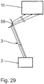
- FIG. 29 an optical element for enlarging the cross section of a beam with illumination radiation 3 is shown.
- a mirror 58 with a convex reflection surface is arranged in the beam path of the illumination radiation 3.
- the mirror 58 is also referred to as a diverging mirror.
- the mirror 58 may have a substantially cylindrical reflection surface, that is convex in a first direction and flat in a second direction perpendicular to the first direction. It can also be convex in both directions.
- the radii of curvature may be identical or different.
- the mirror 58 can thus be used for the targeted enlargement of the cross section of the beam or of the radiation beam with illumination radiation 3.
Abstract
Description
- Der Inhalt der deutschen Patentanmeldung
10 2013 223 935.1 wird durch Bezugnahme hierin aufgenommen. - Die Erfindung betrifft eine Strahlführungsoptik für ein Beleuchtungssystem für die EUV-Projektionslithographie. Außerdem betrifft die Erfindung ein Beleuchtungssystem für die EUV-Projektionslithographie und eine Projektionsbelichtungsanlage für die EUV-Lithographie. Schließlich betrifft die Erfindung ein Verfahren zur Herstellung eines strukturierten Bauteils sowie ein nach diesem Verfahren hergestelltes strukturiertes Bauteil.
- Eine Projektionsbelichtungsanlage mit einem Beleuchtungssystem ist bekannt aus der
US 2011/0 014 799 A1 , aus derWO 2009/121 438 A1 , aus derUS 2009/0 174 876 A1 , aus derUS 6,438,199 B1 und derUS 6,658,084 B2 . Eine EUV-Lichtquelle ist bekannt aus derDE 103 58 225 B3 und derUS 6,859,515 B . Weitere Komponenten für die EUV-Projektionslithografie sind bekannt aus derUS 2003/0002022 A1 , derDE 10 2009 025 655 A1 , derUS 6,700,952 und derUS 2004/0140440 A . Weitere Referenzen, aus denen eine EUV-Lichtquelle bekannt ist, finden sich in derWO 2009/121 438 A1 . EUV-Beleuchtungsoptiken sind weiterhin bekannt aus derUS 2003/0043359 A1 und derUS 5,896,438 . - Es sind Aufgaben der vorliegenden Erfindung, eine Strahlführungsoptik für ein Beleuchtungssystem für die EUV-Projektkionslithographie sowie ein Beleuchtungssystem für die EUV-Projektionslithographie derart weiterzubilden, dass eine möglichst verlustfreie und gleichzeitig flexible Führung von EUV-Licht einer synchrotron-strahlungsbasierten Lichtquelle bereitgestellt ist.
- Diese Aufgabe ist erfindungsgemäß gelöst durch eine Strahlführungsoptik mit den in Anspruch 1 angegebenen Merkmalen.
- Eine Strahlführungsoptik nach Anspruch 1 ermöglicht es, die EUV-Strahlung durch eine vergleichsweise kleine Durchtrittsöffnung durch eine Blende oder eine Wand hindurchzuführen. Diese ermöglicht eine erwünschte Trennung zwischen verschiedenen Kammern, in denen die EUV-Strahlung geführt ist. Zudem können nach dem Zwischenfokus Baugruppen von Projektionsbelichtungsanlagen genutzt werden, die auf einen Zwischenfokus des EUV-Beleuchtungslichts mit vorgegebener numerischer Apertur abgestimmt sind.
- Eine Fokussier-Baugruppe kann nach Art einer Wolter-Spiegelgruppe vom Typ I, vom Typ II oder vom Typ III ausgeführt sein. Die mindestens zwei Spiegel der Fokussier-Baugruppe können sequentiell im Strahlengang des EUV-Einzel-Ausgabestrahls angeordnet sein.
- Die Fokussier-Baugruppe kann so ausgeführt sein, dass ein Bauraum der Fokussier-Baugruppe längs eines Strahlweges des EUV-Einzel-Ausgabestrahls etwa doppelt so groß ist wie eine große Halbachse eines Ellipsoid-Spiegels der Fokussier-Baugruppe. Die Fokussier-Baugruppe kann so ausgeführt sein, dass ein Bauraum der Fokussier-Baugruppe längs eines Strahlweges des EUV-Einzel-Ausgabestrahls etwa fünfzig Mal so groß ist wie ein Durchmesser des EUV-Einzel-Ausgabestrahls beim Eintritt in die Fokussier-Baugruppe. Die Fokussier-Baugruppe kann so ausgeführt sein, dass für ein Verhältnis b/a aus einer kleinen Halbachse b des Ellipsoid-Spiegels und einer großen Halbachse a des Ellipsoid-Spiegels gilt: 0,7NA < b/a < 0,9NA, wobei NA die numerische Apertur im Zwischenfokus der Fokussier-Baugruppe bezeichnet.
- Die Fokussier-Baugruppe kann so ausgeführt sein, dass sie mindestens einen Paraboloid-Spiegel aufweist, wobei für ein Verhältnis a/f aus einer großen Halbachse a des Ellipsoid-Spiegels und einer Brennweite f des Paraboloid-Spiegels gilt: a/f > 50.
- Die Fokussier-Baugruppe kann so ausgeführt sein, dass ein geringster Ablenkwinkel, den ein Randstrahl des EUV-Einzel-Ausgabestrahls durch die Fokussier-Baugruppe erfährt, nicht größer ist als 5°.
- Die Strahlführung von EUV-Licht bzw. EUV-Strahlung, bereitgestellt von einer synchrotron-strahlungsbasierten Lichtquelle, erfordert aufgrund der Eigenschaften des von einer derartigen Lichtquelle emittierten EUV-Rohstrahls eine spezifische Aufbereitung. Diese Aufbereitung wird durch die erfindungsgemäße Strahlformungsoptik, die Auskoppeloptik sowie die Strahlführungsoptik sowie durch die einzelnen strahlführenden Komponenten, nämlich die Umlenkoptik und die Fokussier-Baugruppe gewährleistet.
- Bei der synchrotron-strahlungsbasierten Lichtquelle kann es sich um einen Freie-Elektronen-Laser (FEL), um einen Undulator, um einen Wiggler oder um einen Röntgenlaser handeln. Die synchrotron-strahlungsbasierte Lichtquelle kann einen Lichtleitwert kleiner als 0,1mm2 oder einen noch kleineren Lichtleitwert aufweisen. Die erfindungsgemäßen Optiken können generell mit der Emission einer Lichtquelle mit einem derart kleinen Lichtleitwert arbeiten, unabhängig davon, ob es sich um eine synchrotron-strahlungsbasierte Lichtquelle handelt.
- Die Strahlformungsoptik sorgt für eine Vorformung eines Sammel-Ausgabestrahls aus dem Rohstrahl zur Vorbereitung einer nachfolgenden Auskopplung über die Auskoppeloptik in Einzel-Ausgabestrahlen. Letztere werden durch die Strahlführungsoptik zum jeweiligen Objektfeld geführt. Es resultiert die Möglichkeit, mit ein und derselben synchrotron-strahlungsbasierten Lichtquelle eine Mehrzahl von Objektfeldern zu beleuchten, was wiederum zur Möglichkeit führt, eine Mehrzahl von Projektionsbelichtungsanlagen, mit denen mikro- bzw. nanostrukturierte Bauelemente, zum Beispiel Halbleiterchips, insbesondere Speicherchips, hergestellt werden können, über ein und dieselbe synchrotron-strahlungsbasierte Lichtquelle zu versorgen.
- Über die Auskoppeloptik und die nachfolgende Strahlführungsoptik lässt sich eine variable Intensitätsverteilung für die Anteile der Strahlungsleistung in den verschiedenen EUV-Einzel-Ausgabestrahlen gewährleisten. Hierdurch kann eine Anpassung an die Anzahl der zu versorgenden Projektionsbelichtungsanlagen sowie eine Anpassung an die von der jeweiligen Projektionsbelichtungsanlage geforderte Lichtleistung erfolgen. Auch unterschiedliche Anforderungen, die zur Herstellung spezifischer Strukturen an die jeweils hierfür erforderliche Lichtleistung bestehen, können dann durch entsprechende Anpassung des Beleuchtungssystems erfüllt werden.
- Eine Umlenkoptik umfasst mindestens vier Umlenkspiegel für streifenden Einfall.
- Die Spiegel für streifenden Einfall sind für einen Einfallswinkel größer als 60° gestaltet. Der Einfallswinkel kann noch größer sein.
- Mindestens einer der Umlenkspiegel für streifenden Einfall kann als konvexer Zylinderspiegel ausgeführt sein. Mindestens einer der Umlenkspiegel für streifenden Einfall kann als konkaver Zylinderspiegel ausgeführt sein. Ausführungen der Umlenkoptik können eine größere Anzahl konkaver Zylinderspiegel als konvexe Zylinderspiegel aufweisen.
- Ein parallel in die Umlenkoptik einfallender EUV-Strahl, insbesondere ein EUV-Einzel-Ausgabestrahl, kann nach Verlassen der Umlenkoptik eine Divergenz von weniger als 1mrad haben. Eine derartige Gestaltung der Umlenkoptik ermöglicht es, den EUV-Strahl über große Entfernung führen zu können.
- Bei der Umlenkoptik lässt sich ein durch die Umlenkoptik erzeugter Aspektverhältnisbeitrag der Strahlführungsoptik an einen Vorgabewert anpassen. Beispielsweise lässt sich ein Aufweitfaktor für das Aspektverhältnis zwischen einem Wert 4 und einem Wert 5 oder zwischen einem Wert 1,5 und einem Wert 2 insbesondere stufenlos verändern. Mindestens einer der Umlenkspiegel für streifenden Einfall der Umlenkoptik kann mit angetrieben veränderbarem Krümmungsradius ausgeführt sein. Hierdurch lässt sich eine weitere Anpassung der optischen Wirkung der Umlenkoptik an einen Vorgabewert erreichen.
- Bei einer Strahlformungsoptik können die Gruppen-Einfallsebenen aufeinander senkrecht stehen. Spiegelgruppen der Strahlformungsoptik können zwei Spiegel, drei Spiegel oder noch mehr Spiegel aufweisen. Durch den Einsatz mehrer Spiegelgruppen mit verschiedenen Gruppen-Einfallsebenen kann die EUV-Strahlung in zwei Querdimensionen unabhängig zur Erzeugung eines gewünschten Aspektverhältnisses beeinflusst werden.
- Die Spiegelgruppen können nach Art von Galilei-Teleskopen gestaltet sein.
- Die Spiegel der Strahlformungsoptik können als z. B. konvexe oder konkave Zylinderspiegel ausgeführt sein.
- Die Spiegel für streifenden Einfall sind für einen Einfallswinkel größer als 60° gestaltet. Der Einfallswinkel kann noch größer sein.
- Eine Anordnung, bei welcher alle Spiegel einer der Spiegelgruppen im Strahlengang nach einem ersten Spiegel einer weiteren Spiegelgruppe und vor einem letzten Spiegel dieser weiteren Spiegelgruppe angeordnet sind, schafft die Möglichkeit, einen großen Abstand zwischen denjenigen Spiegeln ein und derselben Spiegelgruppe zu schaffen, die zur Erzeugung eines gewünschten Aspektverhältnisses beispielsweise einen großen Aufweitfaktor bereitstellen müssen.
- Einfallswinkel der EUV-Strahlung, welche auf allen Spiegeln einer Spiegelgruppe gleich groß sind, ermöglichen eine Transmissions-Optimierung für die EUV-Strahlung beim Durchgang durch die Strahlformungsoptik.
- Einfallswinkel, welche auf mindestens zwei Spiegeln einer der Spiegelgruppen verschieden sind, erhöhen eine Flexibilität bei der Auslegung der Strahlformungsoptik und ermöglichen es beispielsweise, einen streifenden Einfall so an einen vorgegebenen Strahldurchmesser des einfallenden EUV-Strahls anzupassen, dass eine Spiegelgröße innerhalb vorgegebener Dimensionen bleibt.
- Eine Gestaltung der Strahlformungsoptik, bei welcher projiziert auf die Gruppen-Einfallsebene der Spiegelgruppe mit verschiedenen Einfallswinkeln der erzeugte EUV-Sammel-Ausgabestrahl in der gleichen Richtung verläuft wie der EUV-Rohstrahl, der in die Strahlformungsoptik einfällt, ermöglicht es beispielsweise, sowohl den in die Strahlformungsoptik einfallenden als auch den aus der Strahlformungsoptik ausfallenden Strahl horizontal zu führen.
- Eine Divergenz des EUV-Sammel-Ausgabestrahls kann kleiner sein als eine halbe Divergenz des EUV-Rohstrahls. Eine entsprechende Gestaltung der Strahlformungsoptik ermöglicht es, den EUV-Sammel-Ausgabestrahl über große Entfernung führen zu können.
- Mindestens ein Spiegel der Strahlformungsoptik kann eine Abweichung von mindestens 5µm von einem bestangepassten (best fit) Kegelschnitt haben. Mindestens ein Spiegel der Strahlformungsoptik kann als Freiformfläche ausgeführt sein. Entsprechende Spiegelgestaltungen der Strahlformungsoptik erhöhen die Freiheitsgrade, um eine optische Wirkung der Strahlformungsoptik an Vorgabewerte anzupassen.
- Die Aufgabe wird weiter gelöst durch ein Beleuchtungssystem mit einer Strahlführungsoptik gemäß der vorhergehenden Beschreibung. Die Vorteile ergeben sich aus den für die jeweiligen Komponenten beschriebenen.
- Ein Beleuchtungssystem mit einer Strahlformungsoptik und einer Auskoppeloptik nach Anspruch 10 ermöglicht die Bereitstellung einer Mehrzahl von EUV-Einzel-Ausgabestrahlen mit vorgegebenem Aspektverhältnis eines EUV-Strahldurchmessers. Die von der Strahlformungsoptik einerseits und von der Auskoppeloptik und der nachfolgenden Strahlführungsoptik andererseits bereitgestellten Aspektverhältnisbeiträge können noch mit einem gewünschten Soll-Aspektverhältnis multipliziert werden, zum Beispiel mit dem Aspektverhältnis eines zu beleuchtenden Objektfeldes. Das Erzeugen eines gewünschten Aspektverhältnisbeitrages der mehreren Einzel-Ausgabestrahlen von 1:1 wird, ausgehend vom Rohstrahl, verteilt einerseits auf die Erzeugung eines Aspektverhältnisbeitrages ungleich 1 über die Strahlformungsoptik sowie, nach dem Aufteilen des Sammel-Ausgabestrahls in die mehreren Einzel-Ausgabestrahlen, durch die Erzeugung eines entsprechenden Aspektverhältnisbeitrages durch die Auskoppeloptik und die Strahlführungsoptik. Dies ermöglicht auf dem Weg des EUV-Beleuchtungslichts von der Lichtquelle bis zum Objektfeld moderate Aspektverhältnis-Änderungen, die durch die verschiedenen optischen Baugruppen, die der EUV-Strahl durchläuft, herbeigeführt werden müssen. Alternativ kann mit der Strahlformungsoptik zunächst auch ein anderer Aspektverhältnisbeitrag erzeugt werden, beispielsweise ein Aspektverhältnisbeitrag von 1:N für N EUV-Einzel-Ausgabestrahlen. Eine nachfolgende Auskoppeloptik muss den so erzeugten EUV-Sammel-Ausgabestrahl dann noch aufteilen, benötigt dann aber zur Vorgabe der EUV-Einzel-Ausgabestrahlen mit dem Aspektverhältnisbeitrag von jeweils 1:1 keine eigene aspektverhältnisbeeinflussende Wirkung. Auch eine andere Verteilung der Aspektverhältnisbeiträge, die von der Strahlformungsoptik einerseits und von der Auskoppeloptik bzw. der Strahlführungsoptik andererseits erzeugt werden, zur Erzeugung einer Anzahl N von EUV-Einzel-Ausgabestrahlen mit einem Aspektverhältnisbeitrag von jeweils 1:1, ist möglich.
- Die Vorteile einer Projektionsbelichtungsanlage nach Anspruch 13, eines Herstellungsverfahrens nach Anspruch 14 und eines strukturierten Bauteils nach Anspruch 15 entsprechen denen, die vorstehend unter Bezugnahme auf die vorhergehenden Ansprüche bereits erläutert wurden.
- Bei der Lichtquelle des Beleuchtungssystems kann es sich um einen Freie-Elektronen-Laser (FEL), um einen Undulator, um einen Wiggler oder um einen Röntgenlaser handeln.
- Der EUV-Sammel-Ausgabestrahl kann innerhalb eines Nutzquerschnitts eine Intensitätsverteilung aufweisen, die in jedem Punkt des Nutzquerschnitts von einer homogenen Intensität um weniger als 10 % abweicht. Eine entsprechende Homogenität kann ein jeweiliger EUV-Einzel-Ausgabestrahl nach der Umlenkoptik aufweisen.
- Alle Spiegel des Beleuchtungssystems können hochreflektierende Beschichtungen tragen.
- Die Strahlformungsoptik, die Umlenkoptik und die Fokussier-Baugruppe sind Baugruppen, die auch eigenständig, also ohne die weiteren Baugruppen des Beleuchtungssystems, erfindungswesentlich sind.
- Alle Anspruchsmerkmale können auch in anderer Kombination miteinander kombiniert werden.
- Ausführungsbeispiele der Erfindung werden nachfolgend anhand der Zeichnung näher erläutert. In dieser zeigen:
- Fig. 1
- schematisch eine Projektionsbelichtungsanlage für die EUV-Projektionslithographie;
- Fig. 2
- ebenfalls schematisch einen führenden Abschnitt eines EUV-Strahlengangs für ein System mehrerer Projektionsbelichtungsanlagen nach
Fig. 1 , ausgehend von einer EUV-Lichtquelle zur Erzeugung eines EUV-Rohstrahls bis nach einer Auskoppeloptik zur Erzeugung mehrerer EUV-Einzel-Ausgabestrahlen aus einem EUV-Sammel-Ausgabestrahl; - Fig. 3
- Querschnittsverhältnisse der EUV-Strahlung im Verlauf des EUV-Strahlengangs zwischen der Lichtquelle und der Bündelführung in einer einem Objektfeld der Projektionsbelichtungsanlage vorgelagerten Beleuchtungsoptik;
- Fig. 4
- eine Seitenansicht einer Strahlformungsoptik zur Erzeugung des EUV-Sammel-Ausgabestrahls aus dem EUV-Rohstrahl;
- Fig. 5
- eine weitere Seitenansicht aus Richtung V in
Fig. 4 ; - Fig. 6 und 7
- stark schematisch die Strahlformungsoptik nach den
Fig. 4 und 5 zur Verdeutlichung von Umlenkwinkeln, die von Spiegeln der Strahlformungsoptik hervorgerufen werden; - Fig. 8 und 9
- in einer zu den
Fig. 6 und 7 ähnlichen Darstellung eine weitere Ausführung einer Strahlformungsoptik; - Fig. 10 und 11
- in einer zu den
Fig. 6 und 7 ähnlichen Darstellung eine weitere Ausführung einer Strahlformungsoptik; - Fig. 12
- weniger schematisch als in den
Fig. 1 und2 einen EUV-Strahlengang zwischen der Strahlformungsoptik und einer Umlenkoptik als Teil einer Strahlführungsoptik zur Führung des jeweiligen EUV-Einzel-Ausgabestrahls hin zum Objektfeld, wobei die Umlenkoptik der Auskoppeloptik im Strahlengang des EUV-Einzel-Ausgabestrahls nachgeordnet ist; - Fig. 13
- in einem Schnitt parallel zur Einfallsebene auf den Umlenkspiegeln stark schematisch eine Ausführung der Umlenkoptik mit im Strahlengang des EUV-Einzel-Ausgabestrahls zunächst zwei konvexen Zylinderspiegeln, einem nachfolgenden Planspiegel und drei nachfolgenden konkaven Zylinderspiegeln;
- Fig. 14
- in einer zu
Fig. 13 ähnlichen Darstellung eine weitere Ausführung der Umlenkoptik mit einem konvexen Zylinderspiegel und im EUV-Strahlengang sich sequentiell anschließenden drei konkaven Zylinderspiegeln; - Fig. 15
- in einer zu
Fig. 13 ähnlichen Darstellung eine weitere Ausführung der Umlenkoptik mit sequentiell im EUV-Strahlengang nacheinander angeordnet einem konvexen Zylinderspiegel, einem Planspiegel und zwei konkaven Zylinderspiegeln; - Fig. 16
- in einer zu
Fig. 13 ähnlichen Darstellung eine weitere Ausführung der Umlenkoptik mit sequentiell im EUV-Strahlengang nacheinander angeordnet einem konvexen Zylinderspiegel, einem Planspiegel und drei konkaven Zylinderspiegeln; - Fig. 17
- in einer zu
Fig. 13 ähnlichen Darstellung eine weitere Ausführung der Umlenkoptik mit sequentiell im EUV-Strahlengang nacheinander angeordnet einem konvexen Zylinderspiegel, zwei nachfolgenden konkaven Zylinderspiegeln, einem nachfolgenden Planspiegeln und zwei nachfolgenden konkaven Zylinderspiegeln; - Fig. 18
- in einer zu
Fig. 13 ähnlichen Darstellung eine weitere Ausführung der Umlenkoptik mit sequentiell im EUV-Strahlengang nacheinander angeordnet einem konvexen Zylinderspiegel, einem nachfolgenden Planspiegel und vier sequentiell nachfolgenden konkaven Zylinderspiegeln; - Fig. 19
- in einer zu
Fig. 13 ähnlichen Darstellung eine weitere Ausführung der Umlenkoptik mit sequentiell im EUV-Strahlengang nacheinander angeordnet einem konvexen Zylinderspiegel, zwei sequentiell nachfolgenden Planspiegeln und drei sequentiell nachfolgenden konkaven Zylinderspiegeln; - Fig. 20
- einen Ausschnitt des Strahlengangs eines der EUV-Einzel-Ausgabestrahlen zwischen der Umlenkoptik und einer Zwischenfokusebene zur Verdeutlichung der Funktion einer Fokussier-Baugruppe bzw. Einkoppeloptik der Strahlführungsoptik zur Führung des jeweiligen EUV-Einzel-Ausgabestrahls zum Objektfeld;
- Fig. 21
- in einer zu
Fig. 20 ähnlichen Darstellung eine weitere Ausführung der Einkoppeloptik; - Fig. 22
- eine Ausführung der Einkoppeloptik des Typs Wolter I;
- Fig. 23
- eine Ausführung der Einkoppeloptik des Typs Wolter II;
- Fig. 24
- eine Ausführung der Einkoppeloptik des Typs Wolter III;
- Fig. 25
- eine weitere Ausführung der Einkoppeloptik des Typs Wolter III,
- Fig. 26 bis 28
- unterschiedliche Varianten einer Strahlformungsoptik;
- Fig. 29
- eine schematische Darstellung einer Strahlaufweitungskomponente.
- Eine Projektionsbelichtungsanlage 1 für die Mikrolithographie ist Teil eines Systems aus mehreren Projektionsbelichtungsanlagen, von denen in der
Fig. 1 eine der Projektionsbelichtungsanlagen 1 dargestellt ist. Die Projektionsbelichtungsanlage 1 dient zur Herstellung eines mikro- bzw. nanostrukturierten elektronischen Halbleiter-Bauelements. Eine für alle Projektionsbelichtungsanlagen des System gemeinsame Licht- bzw. Strahlungsquelle 2 emittiert EUV-Strahlung im Wellenlängebereich beispielsweise zwischen 2 nm und 30 nm, insbesondere zwischen 2 nm und 15 nm. Die Lichtquelle 2 ist als Freie-Elektronen-Laser (FEL) ausgeführt. Es handelt sich dabei um eine Synchrotronstrahlungsquelle bzw. um eine synchrotron-strahlungsbasierte Lichtquelle, die kohärente Strahlung mit sehr hoher Brillanz erzeugt. Vorveröffentlichungen, in denen derartige FEL beschrieben sind, sind in derWO 2009/121 438 A1 angegeben. Eine Lichtquelle 2, die beispielsweise zum Einsatz kommen kann, ist beschrieben in Uwe Schindler "Ein supraleitender Undulator mit elektrisch umschaltbarer Helizität", Forschungszentrum Karlsruhe in der Helmholtz-Gemeinschaft, wissenschaftliche Berichte, FZKA 6997, August 2004, in derUS 2007/0152171 A1 und in derDE 103 58 225 B3 . - Die Lichtquelle 2 hat in einem Rohstrahl einen ursprünglichen Lichtleitwert, der kleiner ist als 0,1 mm2. Beim Lichtleitwert handelt es sich um das kleinste Volumen eines Phasenraums, der 90 % der Lichtenergie einer Emission einer Lichtquelle enthält. Hierzu entsprechende Definitionen des Lichtleitwertes finden sich in der
EP 1 072 957 A2 und derUS 6 198 793 B1 , in denen angegeben ist, dass der Lichtleitwert durch Multiplikation der Beleuchtungsdaten x, y und NA2 erhalten ist, wobei x und y die Felddimensionen sind, die ein beleuchtetes Beleuchtungsfeld aufspannen und NA die numerische Apertur der Feldbeleuchtung. Auch noch kleinere Lichtleitwerte der Lichtquelle als 0,1 mm2 sind möglich, beispielsweise ein Lichtleitwert kleiner als 0,01 mm2. - Die EUV-Lichtquelle 2 hat eine Elektronenstrahl-Versorgungseinrichtung zur Erzeugung eines Elektronenstrahls und eine EUV-Generationseinrichtung. Letztere wird über die Elektronenstrahl-Versorgungseinrichtung mit dem Elektronenstrahl versorgt. Die EUV-Generationseinrichtung ist als Undulator ausgeführt. Der Undulator kann optional durch Verlagerung verstellbare Undulatormagnete aufweisen. Der Undulator kann Elektromagnete aufweisen. Auch ein Wiggler kann bei der Lichtquelle 2 vorgesehen sein.
- Die Lichtquelle 2 hat eine mittlere Leistung von 2,5 kW. Die Pulsfrequenz der Lichtquelle 2 beträgt 30 MHz. Jeder einzelne Strahlungsimpuls trägt dann eine Energie von 83 µJ. Bei einer Strahlungsimpulslänge von 100 fs entspricht dies einer Strahlungsimpulsleistung von 833 MW.
- Eine Repetitionsrate der Lichtquelle 2 kann im Kilohertzbereich, beispielsweise bei 100 kHz, oder im niedrigeren Megahertzbereich, beispielsweise bei 3 MHz, im mittleren Megahertzbereich, beispielsweise bei 30 MHz, im oberen Megahertzbereich, beispielsweise bei 300 MHz, oder auch im Gigaherzbereich, beispielsweise bei 1,3 GHz, liegen.
- Zur Erleichterung der Darstellung von Lagebeziehungen wird nachfolgend ein kartesisches xyz-Koordinatensystem verwendet. Die x-Koordinate spannt mit der y-Koordinate bei diesen Darstellungen regelmäßig einen Bündelquerschnitt des EUV-Beleuchtungs- und Abbildungslichts 3 auf. Entsprechend verläuft die z-Richtung regelmäßig in der Strahlrichtung des Beleuchtungs- und Abbildungslichts 3. Die x-Richtung verläuft zum Beispiel in den
Fig. 2 und12 vertikal, also senkrecht zu Gebäudeebenen, in denen das System der Projektionsbelichtungsanlagen 1 untergebracht ist. Das Koordinatensystem derFig. 4 bis 11 ist hierzu um 90° um die z-Achse verdreht. -
Fig. 1 zeigt stark schematisch Hauptkomponenten einer der Projektionsbelichtungsanlagen 1 des Systems. - Die Lichtquelle 2 imitiert Beleuchtungs- und Abbildungslicht 3 in Form zunächst eines EUV-Rohstrahls 4.
Fig. 3 zeigt stark schematisch links einen Querschnitt durch den EUV-Rohstrahl 4 mit einem x/y-Aspektverhältnis von 1:1. In der Regel liegt der Rohstrahl 4 als Bündel mit einem gaußförmigen Intensitätsprofil vor, also als im Querschnitt rundes Bündel, was in derFig. 3 durch eine gestrichelte Begrenzungslinie 5 angedeutet ist. Der EUV-Rohstrahl 4 hat eine sehr kleine Divergenz. - Eine Strahlformungsoptik 6 (vgl.
Fig. 1 ) dient zur Erzeugung eines EUV-Sammel-Ausgabestrahls 7 aus dem EUV-Rohstrahl 4. Dies ist in derFig. 1 sehr stark schematisch und in derFig. 2 etwas weniger stark schematisch dargestellt. Der EUV-Sammel-Ausgabestrahl 7 hat eine sehr kleine Divergenz.Fig. 3 verdeutlicht in der zweiten Querschnittsdarstellung von links wiederum ein Aspektverhältnis des EUV-Sammel-Ausgabestrahls 7. Dieses Aspektverhältnis wird von der Strahlformungsoptik 6 abhängig von einer Anzahl N der innerhalb des Systems mit der Lichtquelle 2 zu versorgenden Projektionsbelichtungsanlagen 1 vorgegeben. Das x/y-Aspektverhältnis, das durch die Strahlformungsoptik 6 erzeugt wird, beträgt im Allgemeinen
Fig. 3 dargestellt. Der EUV-Sammel-Ausgabestrahl 7 hat die Form eines homogen ausgeleuchteten Rechtecks. Der Aspektverhältnisbeitrag
-
Fig. 2 deutet eine Systemauslegung mit N = 4 an, bei der die Lichtquelle 2 also vier Projektionsbelichtungsanlagen nach Art der Projektionsbelichtungsanlage 1 nachFig. 1 mit dem Beleuchtungslicht 3 versorgt. Für N = 4 beträgt das x/y-Aspektverhältnis des EUV-Sammel-Ausgabestrahls 72:1. Die Anzahl N der Projektionsbelichtungsanlagen 1 kann auch noch größer sein und kann beispielsweise bis zu 10 betragen. - Bei einer alternativen Systemauslegung hat der EUV-Sammel-Ausgabestrahl ein x/y-Aspektverhältnis von N:1. Auch dieses Verhältnis kann noch mit einem gewünschten Soll-Aspektverhältnis multipliziert werden.
- Eine Auskoppeloptik 8 (vgl.
Fig. 1 und2 ) dient zur Erzeugung von mehreren, nämlich von N, EUV-Einzel-Ausgabestrahlen 91 bis 9N (i = 1,... N) aus dem EUV-Sammel-Ausgabestrahl 7. DieFig. 1 zeigt die weitere Führung genau eines dieser EUV-Einzel-Ausgabestrahlen 9, nämlich des Ausgabestrahls 91. Die anderen, von der Auskoppeloptik 8 erzeugten EUV-Einzel-Ausgabestrahlen 9i, die in derFig. 1 ebenfalls schematisch angedeutet ist, werden anderen Projektionsbelichtungsanlagen des Systems zugeführt. - Nach der Auskoppeloptik 8 wird das Beleuchtungs- und Abbildungslicht 3 von einer Strahlführungsoptik 10 (vgl.
Fig. 1 ) hin zu einem Objektfeld 11 der Projektionsbelichtungsanlage 1 geführt, indem eine Lithografiemaske 12 in Form eines Retikels als zu projizierendes Objekt angeordnet ist. Zusammen mit der Strahlführungsoptik 10 stellen die Strahlformungsoptik 6 und die Auskoppeloptik 8 ein Beleuchtungssystem für die Projektionsbelichtungsanlage 1 dar. - Die Strahlführungsoptik 10 umfasst in der Reihenfolge des Strahlengangs für das Beleuchtungslicht 3, also für den EUV-Einzel-Ausgabestrahl 9i, eine Umlenkoptik 13, eine Einkoppeloptik in Form einer Fokussier-Baugruppe 14 und eine nachgeschaltete Beleuchtungsoptik 15. Die Beleuchtungsoptik 15 beinhaltet einen Feldfacettenspiegel 16 und einen Pupillenfacettenspiegel 17, deren Funktion derjenigen entspricht, die aus dem Stand der Technik bekannt ist und die daher in der
Fig. 1 lediglich äußerst schematisch und ohne zugehörigen EUV-Strahlengang dargestellt sind. - Nach Reflexion am Feldfacettenspiegel 16 trifft das in EUV-Strahlbüschel, die einzelnen, nicht dargestellten Feldfacetten des Feldfacettenspiegels 16 zugeordnet sind, aufgeteilte Nutzstrahlungsbündel des Beleuchtungslichts 3 auf den Pupillenfacettenspiegel 17. In der
Fig. 1 nicht dargestellte Pupillenfacetten des Pupillenfacettenspiegels 17 sind rund. Jedem von einer der Feldfacetten reflektierten Strahlbüschel des Nutzstrahlungsbündels ist eine dieser Pupillenfacetten zugeordnet, so dass jeweils ein beaufschlagtes Facettenpaar mit einer der Feldfacetten und einer der Pupillenfacetten einen Ausleuchtungskanal bzw. Strahlführungskanal für das zugehörige Strahlbüschel des Nutzstrahlungsbündels vorgibt. Die kanalweise Zuordnung der Pupillenfacetten zu den Feldfacetten erfolgt abhängig von einer gewünschten Beleuchtung durch die Projektionsbelichtungsanlage 1. Das Beleuchtungslicht 3 ist also zur Vorgabe individueller Beleuchtungswinkel längs des Ausleuchtungskanals sequentiell über Paare aus jeweils einer der Feldfacetten und jeweils einer der Pupillenfacette geführt. Zur Ansteuerung jeweils vorgegebener Pupillenfacetten werden die Feldfacettenspiegel jeweils individuell verkippt. - Über den Pupillenfacettenspiegel 17 und ggf. über eine nachfolgende, aus zum Beispiel drei nicht dargestellten EUV-Spiegeln bestehende Übertragungsoptik werden die Feldfacetten in das Beleuchtungs- bzw. Objektfeld 11 in einer Retikel- bzw. Objektebene 18 einer in der
Fig. 1 ebenfalls schematisch dargestellten Projektionsoptik 19 der Projektionsbelichtungsanlage 1 abgebildet. - Aus den einzelnen Beleuchtungswinkeln, die über alle Ausleuchtungskanäle über eine Beleuchtung der Feldfacetten des Feldfacettenspiegels 16 herbeigeführt werden, ergibt sich eine Beleuchtungswinkelverteilung der Beleuchtung des Objektfeldes 11 durch die Beleuchtungsoptik 15.
- Bei einer weiteren Ausführung der Beleuchtungsoptik 15, insbesondere bei einer geeigneten Lage einer Eintrittspupille der Projektionsoptik 19, kann auf die Spiegel der Übertragungsoptik vor dem Objektfeld 11 auch verzichtet werden, was zu einer entsprechenden Transmissionserhöhung der Projektionsbelichtungsanlage 1 für das Nutzstrahlungsbündel führt.
- In der Objektebene 18 im Bereich des Objektfeldes 11 ist das das Nutzstrahlungsbündel reflektierende Retikel 12 angeordnet. Das Retikel 12 wird von einem Retikelhalter 20 getragen, der über einen Retikelverlagerungsantrieb 21 angesteuert verlagerbar ist.
- Die Projektionsoptik 19 bildet das Objektfeld 11 in ein Bildfeld 22 in einer Bildebene 23 ab. In dieser Bildebene 23 ist bei der Projektionsbelichtung ein Wafer 24 angeordnet, der eine lichtempfindliche Schicht trägt, die während der Projektionsbelichtung mit der Projektionsbelichtungsanlage 1 belichtet wird. Der Wafer 24 wird von einem Waferhalter 25 getragen, der wiederum über einen Waferverlagerungsantrieb 26 gesteuert verlagerbar ist.
- Bei der Projektionsbelichtung werden sowohl das Retikel 12 als auch der Wafer 24 in der
Fig. 1 in x-Richtung durch entsprechende Ansteuerung des Retikelverlagerungsantriebs 21 und des Waferverlagerungsantriebs 26 synchronisiert gescannt. Der Wafer wird während der Projektionsbelichtung mit einer Scangeschwindigkeit von typisch 600 mm/s in der x-Richtung gescannt.Fig. 4 und 5 zeigen eine Ausführung der Strahlformungsoptik 6. Die Strahlformungsoptik 6 nach denFig. 4 und 5 hat insgesamt vier Spiegel BS1, BS2, BS3 und BS4, die in der Reihenfolge ihrer Beaufschlagung durch das Beleuchtungslicht 3 durchnummeriert sind.Fig. 4 zeigt die Strahlformungsoptik 6 in einer Ansicht parallel zur xz-Ebene.Fig. 5 zeigt die Strahlformungsoptik 6 in einer Aufsicht parallel zur yz-Ebene. - Die Darstellung einer Strahlumlenkung durch die Spiegel BS1 bis BS4 der Strahlformungsoptik 6 ist in den
Fig. 4 und 5 insoweit von der Realität abweichend, als die Spiegel BS1 und BS4 in derFig. 4 und die Spiegel BS2 und BS3 in derFig. 5 jeweils beide in der Aufsicht mit dem Betrachter zugewandter Reflexionsfläche dargestellt sind. Tatsächlich ist eine Reflexionsfläche des Spiegels BS4 in derFig. 4 und eine Reflexionsfläche des Spiegels BS3 in derFig. 5 vom Betrachter abgewandt. - Die Spiegel BS1 bis BS4 werden allesamt unter streifendem Einfall mit dem Beleuchtungslicht 3 beaufschlagt. Ein streifender Einfall liegt dann vor, wenn ein Einfallswinkel α zwischen einer Einfalls- bzw. Ausfalls-Hauptrichtung des Beleuchtungslichts 3 und einer Normalen N auf einen mit dem Beleuchtungslicht 3 beaufschlagten Reflexionsflächenabschnitt des jeweiligen Spiegels größer ist als 60°. Der Einfallswinkel α kann beispielsweise größer sein als 65°, kann größer sein als 70° und kann auch größer sein als 75°.
- Die Strahlformungsoptik 6 nach den
Fig. 4 und 5 hat zwei Strahlformungs-Spiegelgruppen 27, 28, nämlich einerseits die Strahlformungs-Spiegelgruppe 27 mit den Spiegeln BS1 und BS4, die in derFig. 4 auch mit 271 und 272 bezeichnet sind, und die Strahlformungs-Spiegelgruppe 28 mit den Spiegeln BS2 und BS3, die in derFig. 5 auch mit 281 und 282 bezeichnet sind. Jede Spiegelgruppe 27, 28 hat eine gemeinsame Gruppen-Einfallsebene. Die Einfallsebene der Spiegelgruppe 27 ist parallel zur yz-Ebene (Zeichenebene derFig. 5 ). Die Gruppen-Einfallsebene der Spiegelgruppe 28 ist parallel zur xz-Ebene (Zeichenebene derFig. 4 ). Die beiden Gruppen-Einfallsebenen yz und xz der Spiegelgruppen 27, 28 unterscheiden sich also voneinander und stehen bei der dargestellten Ausführung senkrecht aufeinander. - Die Strahlformungs-Spiegelgruppe 27 dient zur Strahlformung des EUV-Sammel-Ausgabestrahls 7 in der yz-Ebene. Die Strahlformungs-Spiegelgruppe 28 dient zur Strahlformung des EUV-Sammel-Ausgabestrahl 7 in der xz-Ebene.
- Die Strahlformungs-Spiegelgruppen 27 einerseits und 28 andererseits haben prinzipiell die Wirkung eines Galilei-Zylinderteleskops. Um eine Umformung des Strahlprofils zu erreichen, zum Beispiel aus einen im wesentlichen runden Rohstrahl 4 mit einem gaußförmigen Intensitätsprofil in einen im wesentlichen rechteckigen EUV-Sammel-Ausgabestrahl 7 mit homogenem Intensitätsprofil innerhalb eines rechteckigen Nutz-Querschnitts, können zumindest einige der Spiegel der Strahlformungs-Spiegelgruppen 27 und/oder 28 mit einem Freiformprofil versehen sein, also als Reflexionsfläche eine Freiformfläche aufweisen. Ein Freiformprofil ist ein Höhenprofil, welches nicht als Kegelschnitt darstellbar ist. Unter Kegelschnitt sei hier auch eine Oberflächenform verstanden, die in zwei orthogonalen Richtungen durch einen unterschiedlichen Kegelschnitt beschrieben wird; ein Beispiel für eine solche Oberflächenform ist ein Zylinder. Ein Freiformprofil ist auch durch einen solchen Kegelschnitt nicht beschreibbar. Die Abweichung des Höhenprofils eines oder mehrerer Spiegel der Strahlformungsoptik 6 kann mehr als 1 Mikrometer (µm) betragen, insbesondere mehr als 5 Mikrometer und insbesondere mehr als 20 Mikrometer.
- Die Spiegelgruppe 28 mit den Spiegeln BS2 und BS3 ist insgesamt im Strahlengang nach dem ersten Spiegel BS1 der weiteren Spiegelgruppe 27 und vor dem zweiten und letzten Spiegel BS4 dieser weiteren Spiegelgruppe 27 angeordnet.
- Je nach Ausführung der Strahlformungsoptik 6 können die Einfallswinkel des Beleuchtungslichts 3 auf allen Spiegeln einer der Spiegelgruppen 27, 28 gleich groß sein oder können auf mindestens zwei Spiegeln einer der Spiegelgruppen 27, 28 verschieden groß sein. Unter Einfallswinkel wird in diesem Zusammenhang der Einfallswinkel eines Strahls, der zentral im EUV-Rohstrahl 4 verläuft, verstanden.
- Der Spiegel BS1 ist als konvexer Zylinderspiegel ausgeführt, dessen Zylinderachse parallel zur x-Achse verläuft. Der Spiegel BS2 ist als konvexer Zylinderspiegel ausgeführt, dessen Zylinderachse parallel zur y-Achse verläuft. Der Spiegel BS3 ist als konkaver Zylinderspiegel ausgeführt, dessen Zylinderachse parallel zur y-Richtung verläuft. Der Spiegel BS4 ist als konkaver Zylinderspiegel ausgeführt, dessen Zylinderachse parallel x-Achse verläuft.
- Die Spiegelgruppe 27 sorgt für eine Aufweitung eines Bündeldurchmessers des Rohstrahls in der x-Dimension um einen Faktor 2 im Vergleich zur aufweitenden Wirkung der Spiegelgruppe 28 in der y-Dimension. Ferner dienen die beiden Spiegelgruppen 27, 28 zur Formung der Rechteck-Querschnittskontur des EUV-Sammel-Ausgabestrahls 7.
-
Fig. 6 bis 11 zeigen weitere Ausführungen der Strahlformungsoptik 6. Diese Ausführungen unterscheiden sich in der Abfolge der über die verschiedenen Strahlformungsspiegel BSi (i = 1, ...) erzeugten Umlenkwinkel. Es ist daher in denFig. 6 bis 11 nur jeweils die Umlenkwirkung der Spiegel BSi dargestellt, ohne dass die Spiegel selbst körperlich angedeutet sind. - Die Ausführung der Strahlformungsoptik 6 nach den
Fig. 6 und 7 entspricht hinsichtlich der Einfallswinkel des Beleuchtungslichts 3 auf den Spiegeln BS1 bis BS4 und auch hinsichtlich der Zuordnung der Spiegel BS1 bis BS4 zu den Spiegelgruppen 27, 28 der Ausführungen nach denFig. 4 und 5 . Die Einfallswinkel α des Beleuchtungslichts 3 an den Spiegelns BS1 bis BS4 ist für alle diese Spiegel bei der Ausführung nach denFig. 6 und 7 identisch. Eine Haupt-Strahlrichtung des EUV-Sammel-Ausgabestrahls 7 ist damit identisch zur Haupt-Strahlrichtung des in die Strahlformungsoptik 6 einfallenden EUV-Rohstrahls 4. -
Fig. 8 und 9 zeigen eine weitere Ausführung einer Strahlformungsoptik 29, die anstelle der Strahlformungsoptik 6 nach denFig. 4 bis 7 zum Einsatz kommen kann. Komponenten und Funktionen, die denjenigen entsprechen, die vorstehend unter Bezugnahme auf die Strahlformungsoptik 6 bereits erläutert wurden, tragen bei der Strahlformungsoptik 29 die gleichen Bezugszeichen und werden nicht nochmals im Einzelnen diskutiert. - Im Unterschied zur Strahlformungsoptik 6 liegen bei der Strahlformungsoptik 29 verschiedene Einfallswinkel α, β der EUV-Strahlung auf den Spiegeln BS1 bis BS4 vor. Die Spiegel BS1 und BS2 reflektieren jeweils mit dem Einfallswinkel α, sodass der Strahlengang der Strahlformungsoptik 29 bis zum dritten Spiegel BS3 mit dem Strahlengang in der Strahlformungsoptik 6 übereinstimmt. An den Spiegeln BS3 und BS4 wird das Beleuchtungslicht 3 mit einem im Vergleich zum Einfallwinkel α kleineren Einfallswinkel β, aber immer noch unter streifendem Einfall, reflektiert. Dies führt dazu, dass eine Haupt-Strahlrichtung des aus der Strahlformungsoptik 29 ausfallenden EUV-Sammel-Ausgabestrahls 7 nicht parallel zur z-Richtung verläuft, sondern sowohl in der xz-Ebene als auch in der yz-Ebene einen von Null verschiedenen Winkel zur Einfallsrichtung, die parallel zur z-Richtung verläuft, einschließt.
- Die kleineren Einfallswinkel β an den beiden letzten Spiegeln BS3 und BS4 der Strahlformungsoptik 29 ermöglichen eine baukleinere Ausführung dieser beiden letzten Spiegel BS3 und BS4, also eine Ausführung mit geringer ausgedehnter Reflexionsfläche. Dies spielt bei diesen beiden letzten Spiegeln BS3 und BS4 der Strahlformungsoptik 29 eine größere Rolle als bei den beiden führenden Spiegeln BS1 und BS2, da am Ort der letzten Spiegel BS3 und BS4 das Beleuchtungslicht bereits im Vergleich zum einfallenden EUV-Rohstrahl im Querschnitt deutlich aufgeweitet ist.
-
Fig. 10 und 11 zeigen eine weitere Ausführung einer Strahlformungsoptik 30, die anstelle der Strahlformungsoptiken 6, 29 zum Einsatz kommen kann. Komponenten und Funktionen, die denjenigen entsprechen, die vorstehend unter Bezugnahme auf die Strahlformungsoptiken 6, 29 bereits erläutert wurden, tragen bei der Strahlformungsoptik 30 die gleichen Bezugszeichen und werden nicht nochmals im Einzelnen diskutiert. - Die Strahlformungsoptik 30 hat insgesamt fünf Strahlformungsspiegel BS1, BS2, BS3, BS4, BS5, die wiederum in der Reihenfolge ihrer Beaufschlagung mit dem Beleuchtungslicht 3 innerhalb der Strahlformungsoptik 30 durchnummeriert sind. Die Spiegel BS1, BS2 und BS5 gehören zur ersten Spiegelgruppe 27 der Strahlformungsoptik 30 mit yz-Einfallsebene. Die beiden verbleibenden Spiegel BS3 und BS4 gehören zur Spiegelgruppe 28 mit xz-Einfallsebene.
- Nach Reflexion am ersten Spiegel BS1 entspricht der Strahlengang des Beleuchtungslichts 3 in der Strahlformungsoptik 30 demjenigen in der Strahlformungsoptik 29, wobei dann die Spiegel BS2 bis BS5 der Strahlformungsoptik 30 die Funktion der Spiegel BS1 bis BS4 der Strahlformungsoptik 29 haben.
- Der erste BS1 der Strahlformungsoptik 30 wird vom Beleuchtungslicht 3, also vom EUV-Rohstrahl 4, unter einem sehr streifenden Einfall beaufschlagt. Ein Einfallswinkel γ des Beleuchtungslichts 3 auf dem ersten Spiegel BS1 der Strahlformungsoptik 30 ist also größer als der Einfallswinkel α. Der Einfallswinkel γ ist so groß, dass er einen Strahlrichtungsunterschied des Beleuchtungslichts 3, den das Beleuchtungslicht 3 zwischen den Spiegeln BS1 und BS2 einerseits und nach dem Spiegel BS5 andererseits in der yz-Ebene aufweist, genau kompensiert, sodass eine Haupt-Strahlrichtung des Beleuchtungslichts 3 in der yz-Ebene nach Austritt aus der Strahlformungsoptik 30 parallel zur Haupt-Strahlrichtung in der yz-Ebene beim Eintritt in die Strahlformungsoptik 30, nämlich parallel zur z-Richtung, ist.
- Vor und nach der Strahlformungsoptik 30 verläuft das Beleuchtungslicht 3 parallel zu den Gebäudedecken des Gebäudes, in dem das System untergebracht ist.
- Projiziert auf die Gruppen-Einfallsebene yz der Spiegelgruppe 27 der Strahlformungsoptik 30, in der die einzelnen Spiegel 271 (BS1), 272 (BS2) und 273 (BS5) unterschiedliche Einfallswinkel, nämlich γ, α und β haben, verläuft der mit der Strahlformungsoptik 30 erzeugte EUV-Sammel-Ausgabestrahl 7 in der gleichen Richtung, nämlich in der z-Richtung, wie der EUV-Rohstrahl 4, der in die Strahlformungsoptik 30 einfällt.
- Eine typische Querschnittsdimension von Reflexionsflächen des letzten Spiegels BS4 bzw. BS5 der Strahlformungsoptik 6 bzw. 30 ist 1m bis 1,5m, wobei diese Spiegel typischerweise eine in erster Näherung rechteckförmige Reflexionsfläche besitzen und die angegebene Querschnittsdimension sich auf die längere der beiden Achsen bezieht. Eine typische Querschnittsdimension von Reflexionsflächen des ersten Spiegels BS1 der Strahlformungsoptik beträgt 20 mm bis 100 mm.
- Nach Verlassen der Strahlformungsoptik 6 bzw. 30 verlaufen die Strahlen des EUV-Sammel-Ausgabestrahls 7 im Wesentlichen parallel. Die Divergenz des EUV-Sammel-Ausgabestrahls 7 kann kleiner als 10 mrad sein, insbesondere kleiner als 1 mrad, insbesondere kleiner als 100 µrad und insbesondere kleiner als 10 µrad.
-
Fig. 2 und12 zeigen Beispiele für die Auskoppeloptik 8 zur Erzeugung der EUV-Einzel-Ausgabestrahlen 9 aus dem EUV-Sammel-Ausgabestrahl 7. Die Auskoppeloptik hat eine Mehrzahl von Auskoppelspiegeln 311, 312, ..., die den EUV-Einzel-Ausgabestrahlen 91, 92, ... zugeordnet sind und diese aus dem EUV-Sammel-Ausgabestrahl 7 auskoppeln.Fig. 2 zeigt eine Anordnung der Auskoppelspiegel 31 derart, dass das Beleuchtungslicht 3 bei der Auskopplung um 90° mit den Auskoppelspiegeln 31 umgelenkt wird. Bevorzugt ist eine Ausführung, bei der die Auskoppelspiegel 31 unter streifendem Einfall des Beleuchtungslichts 3 betrieben werden, wie schematisch in derFig. 12 gezeigt. Ein Einfallswinkel α des Beleuchtungslichts 3 auf den Auskoppelspiegeln 31 ist bei der Ausführung nachFig. 2 etwa 70°, kann aber auch noch deutlich darüber liegen und beispielsweise im Bereich von 85° liegen, sodass eine effektive Umlenkung des EUV-Einzel-Ausgabestrahls 9 durch den jeweiligen Auskoppelspiegel 31 im Vergleich zur Einfallsrichtung des EUV-Sammel-Ausgabestrahls 7 bei 10° liegt. - Jeder der Auskoppelspiegel 31i ist an einen nicht näher dargestellten Kühlkörper thermisch angekoppelt.
-
Fig. 2 zeigt eine Auskoppeloptik 8 mit insgesamt vier Auskoppelspiegeln 311 bis 314.Fig. 12 zeigt eine Variante der Auskoppeloptik 8 mit insgesamt drei Auskoppelspiegeln 311 bis 313. Auch eine andere Anzahl N der Auskoppelspiegel 31 ist möglich, je nach der Anzahl N der mit der Lichtquelle 2 zu versorgenden Projektionsbelichtungsanlagen 1, beispielsweise N = 2 oder N ≥ 4, insbesondere N ≥ 8. - Nach der Auskopplung hat jeder der EUV-Einzel-Ausgabestrahlen 9 ein x/y-Aspektverhältnis von

Fig. 3 ist einer der EUV-Einzel-Ausgabestrahlen 9 mit diesem Aspektverhältnis dargestellt. Für den Fall N = 4 beträgt das x/y-Aspektverhältnis also 1:2. Auch dieser Aspektverhältnisbeitrag kann noch mit dem gewünschten Soll-Aspektverhältnis multipliziert werden. - Die Auskoppelspiegel 31i(i = 1, 2, ...) sind im Strahlengang des EUV-Sammel-Ausgabestrahls 7 versetzt hintereinander so in Strahlrichtung des EUV-Sammel-Ausgabestrahls 7 angeordnet, dass der jeweils nächste Auskoppelspiegel 31i einen randseitigen Querschnittsanteil des EUV-Sammel-Ausgabestrahls 7 reflektiert und dadurch diesen Querschnittsanteil als EUV-Einzel-Ausgabestrahl 9i aus dem verbleibenden und an diesem Auskoppelspiegel 31i vorbeifliegenden EUV-Sammel-Ausgabestrahl 7 auskoppelt. Dieses Auskoppeln vom Rand her wiederholt sich durch die folgenden Auskoppelspiegel 31i+1, ..., bis der letzte noch verbleibende Querschnittsanteil des EUV-Sammel-Ausgabestrahls 7 ausgekoppelt ist.
- Im Querschnitt des EUV-Sammel-Ausgabestrahls 7 erfolgt eine Trennung zwischen den den EUV-Einzel-Ausgabestrahlen 9i zugeordneten Querschnittsanteilen längs Trennlinien 32, die parallel zur y-Achse, also parallel zur kürzeren Seite des x/y-Rechteckquerschnitts des EUV-Sammel-Ausgabestrahls 7 verlaufen. Die Trennung der EUV-Einzel-Ausgabestrahlen 9i kann derart erfolgen, dass jeweils der Querschnittsanteil, der am weitesten von der im Strahlengang nächstfolgenden optischen Komponente entfernt ist, abgeschnitten wird. Dieses erleichtert unter anderem die Kühlung der Auskoppeloptik 8.
- Die der Auskoppeloptik 8 im Strahlengang des Beleuchtungslichts 3 nachfolgende Umlenkoptik 13 dient einerseits zum Umlenken der EUV-Einzel-Ausgabestrahlen 9 so, dass diese nach der Umlenkoptik 13 jeweils eine vertikale Strahlrichtung haben, und andererseits zur Anpassung des x/y-Aspektverhältnisses der EUV-Einzel-Ausgabestrahlen 9 auf ein x/y-Aspektverhältnis von 1:1, wie in der
Fig. 3 ganz rechts dargestellt. Auch dieser Aspektverhältnisbeitrag kann noch mit dem gewünschten Soll-Aspektverhältnis multipliziert werden. Bei den vorstehenden x/y-Aspektverhältnissen, handelt es sich also um Aspektverhältnisbeiträge, die, multipliziert mit einem Soll-Aspektverhältnis, zum Beispiel dem Aspektverhältnis eines rechteckigen oder bogenförmigen Objektfeldes, ein gewünschtes Ist-Aspektverhältnis ergeben. Es kann sich bei den vorstehenden x/y-Soll-Aspektverhältnissen um das Aspektverhältnis eines ersten optischen Elements einer Beleuchtungsoptik 15 handeln. Es kann sich bei den vorstehenden x/y-Soll-Aspektverhältnissen um das Aspektverhältnis der Winkel des Beleuchtungslichts 3 an einem Zwischenfokus 42 einer Beleuchtungsoptik 15 handeln. - Für den Fall, dass nach der Auskoppeloptik 8 bereits ein vertikaler Strahlengang der EUV-Einzel-Ausgabestrahlen 9 vorliegt, kann auf eine umlenkende Wirkung der Umlenkoptik 13 verzichtet werden und es genügt die Anpassungswirkung in Bezug auf das x/y-Aspektverhältnis der EUV-Einzel-Ausgabestrahlen 9.
- Die EUV-Einzel-Ausgabestrahlen 9 können hinter der Umlenkoptik 13 derart verlaufen, dass sie, gegebenenfalls nach Durchlaufen einer Fokussier-Baugruppe 14, unter einem Winkel in die Beleuchtungsoptik 15 treffen, wobei dieser Winkel eine effiziente Faltung der Beleuchtungsoptik erlaubt. Hinter der Umlenkoptik 13 kann der EUV-Einzel-Ausgabestrahl 9i in einem Winkel von 0° bis 10° zur Senkrechten, in einem Winkel von 10° bis 20° zur Senkrechten, oder in einem Winkel von 20° bis 30° zur Senkrechten verlaufen.
- Anhand der
Fig. 13 bis 19 werden nachfolgend verschiedene Varianten für die Umlenkoptik 13 beschrieben. Das Beleuchtungslicht 3 wird dabei schematisch als ein einziger Strahl dargestellt, es wird also auf eine Bündeldarstellung verzichtet. - Die Divergenz des EUV-Einzel-Ausgabestrahls 9i nach Durchlaufen der Umlenkoptik ist kleiner als 10 mrad, insbesondere kleiner als 1 mrad und insbesondere kleiner als 100 µrad, d.h., der Winkel zwischen zwei beliebigen Strahlen im Strahlenbündel des EUV-Einzel-Ausgabestrahls 9i ist kleiner als 20 mrad, insbesondere kleiner als 2 mrad und insbesondere kleiner als 200 µrad. Dies ist für die im folgenden beschriebenen Varianten erfüllt.
- Die Umlenkoptik 13 nach
Fig. 13 lenkt den ausgekoppelten EUV-Einzel-Ausgabestrahl 9 insgesamt um einen Umlenkwinkel von etwa 75° ab. Der EUV-Einzel-Ausgabestrahl 9 fällt auf die Umlenkoptik 13 nachFig. 13 also unter einem Winkel von etwa 15° zur Horizontalen (xy-Ebene) ein und verlässt die Umlenkoptik 13 mit einer Strahlrichtung parallel zur x-Achse in derFig. 13 . Die Umlenkoptik 13 hat eine Gesamttransmission für den EUV-Einzel-Ausgabestrahl 9 von etwa 55 %. - Die Umlenkoptik 13 nach
Fig. 13 hat insgesamt sechs Umlenkspiegel D1, D2, D3, D4, D5 und D6, die in der Reihenfolge ihrer Beaufschlagung im Strahlengang des Beleuchtungslichts 3 durchnummeriert sind. Von den Umlenkspiegeln D1 bis D6 ist schematisch jeweils nur ein Schnitt durch deren Reflexionsfläche dargestellt, wobei eine Krümmung der jeweiligen Reflexionsfläche stark übertrieben dargestellt ist. Alle Spiegel D1 bis D6 der Umlenkoptik 13 nachFig. 13 werden unter streifendem Einfall mit dem Beleuchtungslicht 3 in einer gemeinsamen Umlenk-Einfallsebene parallel zur xz-Ebene beaufschlagt. - Die Spiegel D1 und D2 sind als konvexe Zylinderspiegel mit Zylinderachse parallel zur y-Achse ausgeführt. Der Spiegel D3 ist als Planspiegel ausgeführt. Die Spiegel D4 bis D6 sind als konkave Zylinderspiegel wiederum mit Zylinderachse parallel zur y-Achse ausgeführt.
- Die konvexen Zylinderspiegel werden auch als domförmige Spiegel bezeichnet. Die konkaven Zylinderspiegel werden auch als schüsselförmige Spiegel bezeichnet.
- Die kombinierte bündelformende Wirkung der Spiegel D1 bis D6 ist so, dass das x/y-Aspektverhältnis vom Wert


- Mindestens einer der Umlenkspiegel D1 bis D6 oder auch alle Umlenkspiegel D1 bis D6 können über zugeordnete Aktoren 34 in der x-Richtung und/oder in der z-Richtung verlagerbar ausgeführt sein. Hierdurch kann eine Anpassung einerseits der Umlenkwirkung und andererseits der Aspektverhältnis-Anpassungswirkung der Umlenkoptik 13 herbeigeführt werden. Alternativ oder zusätzlich kann mindestens einer der Umlenkspiegel D1 bis D6 als hinsichtlich seines Krümmungsradius anpassbarer Spiegel ausgeführt sein. Hierzu kann der jeweilige Spiegel D1 bis D6 aus einer Mehrzahl von Einzelspiegeln aufgebaut sein, die aktorisch zueinander verlagerbar sind, was in der Zeichnung nicht dargestellt ist.
- Die verschiedenen optischen Baugruppen des Systems mit den Projektionsbelichtungsanlagen 1 können adaptiv ausgeführt sein. Es kann also zentral vorgegeben werden, wie viele der Projektionsbelichtungsanlagen 1 mit welchem energetischen Verhältnis mit EUV-Einzel-Ausgabestrahlen 9i von der Lichtquelle 2 versorgt werden sollen und welche Bündelgeometrie bei jeweiligen EUV-Einzel-Ausgabestrahl 9 nach Durchlaufen der jeweiligen Umlenkoptik 13 vorliegen soll. Je nach Vorgabewerten können sich die EUV-Einzel-Ausgabestrahlen 9i in ihrer Intensität und auch in ihrem Soll-x/y-Aspektverhältnis unterscheiden. Insbesondere ist es möglich, durch adaptive Einstellung der Auskoppelspiegel 31i die energetischen Verhältnisse der EUV-Einzel-Ausgabestrahlen 9i zu verändern, und durch adaptive Einstellung der Umlenkoptik 13 die Größe und das Aspektverhältnis des EUV-Einzel-Ausgabestrahls 9i nach Durchlaufen der Umlenkoptik 13 unverändert zu halten.
- Anhand der
Fig. 14 bis 19 werden nachfolgend weitere Ausführungen von Umlenkoptiken beschrieben, die anstelle der Umlenkoptik 13 nachFig. 13 bei einem System mit N Projektionsbelichtungsanlagen 1 zum Einsatz kommen können. Komponenten und Funktionen, die vorstehend unter Bezugnahme auf dieFig. 1 bis 13 und insbesondere unter Bezugnahme auf dieFig. 13 bereits erläutert wurden, tragen die gleichen Bezugszeichen und werden nicht nochmals im Einzelnen diskutiert. - Eine Umlenkoptik 35 nach
Fig. 14 hat insgesamt vier Spiegel D1, D2, D3, D4 im Strahlengang des Beleuchtungslichts 3. Der Spiegel D1 ist als konvexer Zylinderspiegel ausgeführt. Die Spiegel D2 bis D4 sind als konkave Zylinderspiegel ausgeführt. - Genauere optische Daten können der nachfolgenden Tabelle entnommen werden. Die erste Spalte bezeichnet hierbei den Krümmungsradius des jeweiligen Spiegels D1 bis D4 und die zweite Spalte den Abstand des jeweiligen Spiegels D1 bis D3 zum jeweils nachfolgenden Spiegel D2 bis D4. Der Abstand bezieht sich auf diejenige Distanz, die ein zentraler Strahl innerhalb des EUV-Einzel-Ausgabestrahls 9i zwischen den entsprechenden Reflexionen zurücklegt. Die in dieser und den nachfolgenden Tabellen verwendete Einheit ist jeweils mm, soweit nichts anderes beschrieben ist. Der EUV-Einzel-Ausgabestrahl 9i fällt hierbei mit einem Halbmesser din/2 von 10mm in die Umlenkoptik 13 ein.
Tabelle zu Fig. 14 Krümmungsradius Abstand zum nächsten Spiegel D1 2922.955800 136.689360 D2 -49802.074797 244.501473 D3 -13652.672229 342.941568 D4 -22802.433560 - Die Umlenkoptik 35 nach
Fig. 14 weitet das x/y-Aspektverhältnis um einen Faktor 3 auf. -
Fig. 15 zeigt eine weitere Ausführung einer Umlenkoptik 36 ebenfalls mit vier Spiegeln D1 bis D4. Der Spiegel D1 ist ein konvexer Zylinderspiegel. Der Spiegel D2 ist ein Planspiegel. Die Spiegel D3 und D4 sind zwei Zylinderspiegel mit identischem Krümmungsradius. - Genauere Daten können der nachfolgenden Tabelle entnommen werden, die vom Aufbau der Tabelle zur
Fig. 14 entspricht.Tabelle zu Fig. 15 Krümmungsradius Abstand zum nächsten Spiegel D1 5080.620899 130.543311 D2 0.000000 187.140820 D3 -18949.299940 226.054877 D4 -18949.299940 - Die Umlenkoptik 36 nach
Fig. 15 weitet das x/y-Aspektverhältnis des EUV-Einzel-Ausgabestrahls 9 um einen Faktor 2 auf. -
Fig. 16 zeigt eine weitere Ausführung einer Umlenkoptik 37 mit fünf Spiegeln D1 bis D5. Der erste Spiegel D1 ist ein konvexer Zylinderspiegel. Der zweite Spiegel D2 ist ein Planspiegel. Die weiteren Spiegel D3 bis D5 sind drei konkave Zylinderspiegel. - Genauere Daten können der nachfolgenden Tabelle entnommen werden, die vom Aufbau den Tabellen zu
Fig. 14 und 15 entspricht.Tabelle zu Fig. 16 Krümmungsradius Abstand zum nächsten Spiegel D1 3711.660251 172.323866 D2 0.000000 352.407636 D3 -27795.782391 591.719804 D4 -41999.478002 717.778100 D5 -101011.739006 - Die Umlenkoptik 37 nach
Fig. 16 weitet das x/y-Aspektverhältnis des EUV-Einzel-Ausgabestrahls 9 um einen Faktor 5 auf. - Eine weitere Ausführung der Umlenkoptik 37 unterscheidet sich von der Ausführung nach
Fig. 16 nur durch die Krümmungsradien und die Spiegelabstände, die in der nachfolgenden Tabelle angegeben sind:Tabelle "Alternativdesign zu Fig. 16" Krümmungsradius Abstand zum nächsten Spiegel D1 4283.491081 169.288384 D2 0.000000 318.152124 D3 -26270.138665 486.408438 D4 -41425.305704 572.928893 D5 -91162.344644 - Im Unterschied zur ersten Ausführung nach
Fig. 16 hat dieses Alternativdesign einen Aufweitfaktor von 4 für das x/y-Aspektverhältnis. - Noch eine weitere Ausführung der Umlenkoptik 37 unterscheidet sich von der Ausführung nach
Fig. 16 durch die Krümmungsradien und die Spiegelabstände, die in der nachfolgenden Tabelle angegeben sind:Tabelle "weiteres Alternativdesign" zu Fig. 16 Krümmungsradius Abstand zum nächsten Spiegel D1 5645.378471 164.790501 D2 0.000000 269.757678 D3 -28771.210382 361.997270 D4 -55107.732703 424.013033 D5 -55107.732703 - Im Unterschied zur vorstehend beschriebenen Ausführungsform hat dieses weitere Alternativdesign einen Aufweitfaktor von 3 für das x/y-Aspektverhältnis. Die Krümmungsradien der beiden letzten Spiegel D4 und D5 sind identisch.
-
Fig. 17 zeigt eine weitere Ausführung einer Umlenkoptik 38 mit sechs Spiegeln D1 bis D6. Der erste Spiegel D1 ist ein konvexer Zylinderspiegel. Die beiden nächsten Umlenkspiegel D2, D3 sind jeweils konkave Zylinderspiegel mit identischem Krümmungsradius. Der nächste Umlenkspiegel D4 ist ein Planspiegel. Die beiden letzten Umlenkspiegel D5, D6 der Umlenkoptik 38 sind wiederum konkave Zylinderspiegel mit identischem Krümmungsradius. - Genauere Daten können der nachfolgenden Tabelle entnommen werden, die vom Aufbau der Tabelle zu
Fig. 16 entspricht.Tabelle zu Fig. 17 Krümmungsradius Abstand zum nächsten Spiegel D1 7402.070457 197.715713 D2 -123031.042588 332.795789 D3 -123031.042588 459.491141 D4 0.000000 608.342998 D5 -87249.129389 857.423893 D6 -87249.129389 - Die Umlenkoptik 38 hat einen Aufweitfaktor von 5 für das x/y-Aspektverhältnis.
-
Fig. 18 zeigt eine weitere Ausführung einer Umlenkoptik 39 mit sechs Spiegeln D1 bis D6. Der erste Spiegel D1 der Umlenkoptik 39 ist ein konvexer Zylinderspiegel. Der nachfolgende zweite Umlenkspiegel D2 ist ein Planspiegel. Die nachfolgenden Umlenkspiegel D3 bis D6 sind jeweils konkave Zylinderspiegel. Die Krümmungsradien der Spiegel D3 und D4 einerseits sowie der Spiegel D5 und D6 andererseits sind identisch. - Genauere Daten können der nachfolgenden Tabelle entnommen werden, die vom Aufbau der Tabelle zu
Fig. 17 entspricht.Tabelle zu Fig. 18 Krümmungsradius Abstand zum nächsten Spiegel D1 7950.882348 196.142128 D2 0.000000 322.719989 D3 -207459.983757 451.327919 D4 -207459.983757 627.317787 D5 -90430.481262 839.555523 D6 -90430.481262 - Die Umlenkoptik 39 hat einen Aufweitfaktor von 5 für das x/y-Aspektverhältnis.
- Bei einem Alternativdesign zu
Fig. 18 ist die Spiegelabfolge konvex/plan/konkav/konkav/konkav/konkav genau wie bei der vorstehend beschriebenen Ausführung der Umlenkoptik 39. Dieses Alternativdesign zuFig. 18 unterscheidet sich in den konkreten Krümmungsradien und Spiegelabständen, wie die nachfolgende Tabelle verdeutlicht:Tabelle "Alternativdesign zu Fig. 18" Krümmungsradius Abstand zum nächsten Spiegel D1 10293.907897 S 192.462359 D2 0.000000 S 285.944981 D3 -101659.408806 S 360.860262 D4 -101659.408806 S 451.967976 D5 -101659.408806 S 517.093086 D6 -101659.408806 - Dieses Alternativdesign zu
Fig. 18 hat einen Aufweitfaktor von 4 für das x/y-Aspektverhältnis des EUV-Einzel-Ausgabestrahls 9. -
Fig. 19 zeigt eine weitere Ausführung einer Umlenkoptik 40 mit sechs Spiegeln D1 bis D6. Der erste Umlenkspiegel D1 der Umlenkoptik 40 ist ein konvexer Zylinderspiegel. Die beiden nachfolgenden Umlenkspiegel D2 und D3 sind Planspiegel. Die nachfolgenden Umlenkspiegel D4 bis D6 der Umlenkoptik 40 sind konkave Zylinderspiegel. Die Krümmungsradien der beiden letzten Umlenkspiegel D5 und D6 sind identisch. - Genauere Daten können der nachfolgenden Tabelle entnommen werden, die vom Aufbau der Tabelle zu
Fig. 18 entspricht.Tabelle zu Fig. 19 Krümmungsradius Abstand zum nächsten Spiegel D1 8304.649871 195.440359 D2 0.000000 314.991402 D3 0.000000 435.995630 D4 -237176.552267 622.135962 D5 -85355.457233 852.531832 D6 -85355.457233 - Die Umlenkoptik 40 hat einen Aufweitfaktor von 5 für das x/y-Aspektverhältnis.
- Bei einer weiteren, nicht dargestellten Variante hat die Umlenkoptik insgesamt acht Spiegel D1 bis D8. Die im Strahlengang des EUV-Einzel-Ausgabestrahls 9 führenden beiden Umlenkspiegel D1 und D2 sind konkave Zylinderspiegel. Die vier nachfolgenden Umlenkspiegel D3 bis D6 sind konvexe Zylinderspiegel. Die beiden letzten Umlenkspiegel D7 und D8 dieser Umlenkoptik sind wiederum konkave Zylinderspiegel.
- Diese Spiegel D1 bis D8 sind vergleichbar zum Spiegel D1 der
Fig. 13 mit Aktoren 34 verbunden, über die ein Abstand zwischen benachbarten Spiegeln D1 bis D8 vorgegeben werden kann. - Die nachfolgende Tabelle zeigt die Auslegung dieser Umlenkoptik mit den acht Spiegeln D1 bis D8, wobei neben den Krümmungsradien auch die Spiegelabstände für verschiedenen Halbmesser dout/2 des ausfallenden EUV-Einzel-Ausgabestrahls 9i angeben sind. Der EUV-Einzel-Ausgabestrahl fällt hierbei mit einer Halbmesser din/2 von 10mm in die Umlenkoptik mit acht Spiegeln D1 bis D8 ein, sodass je nach den angegebenen Abstandswerten Aufweitfaktoren für das x/y-Aspektverhältnis des umgelenkten EUV-Einzel-Ausgabestrahls 9i von 4,0, von 4,5 und von 5,0 realisiert werden.
Krüummungsradius [mm] 40 mm Halbmesser Abstände [mm] für 45 mm Halbmesser 50 mm Halbmesser D1 -24933.160828 233.314949 313.511608 355.515662 D2 -96792.387128 261.446908 184.453510 159.189884 D3 13933.786194 120.747224 278.984993 124.048048 D4 7248.275614 150.818354 311.248621 385.643707 D5 29532.874950 204.373669 219.654058 296.180993 D6 100989.002210 872.703663 698.841397 665.602749 D7 -87933.616578 1176.395997 1462.002885 1318.044212 D8 -79447.352117 - Bei einer weiteren, ebenfalls nicht dargestellten Ausführung der Umlenkoptik sind vier Spiegel D1 bis D4 vorhanden. Der erste Spiegel D1 und der dritte Spiegel D3 im Strahlengang des EUV-Einzel-Ausgabestrahls 9i sind als konvexe Zylinderspiegel und die beiden weiteren Spiegel D2 und D4 sind als konkave Zylinderspiegel ausgeführt. In der nachfolgenden Tabelle sind neben den Krümmungsradien auch Abstandswerte angeben, die für einen Eingangs-Halbmesser din/2 des EUV-Einzel-Ausgabestrahls 9i von 10mm gerechnet sind, die also zu Aufweitfaktoren beim Durchgang durch diese Umlenkgruppe mit den vier Spiegeln D1 bis D4 für das x/y-Aspektverhältnis von 1,5, (Halbmesser dout/2 15mm) von 1,75 (Halbmesser dout/2 17,5mm) und von 2,0 (Halbmesser dout/2 20mm) führen.
Krümmungsradius [mm] 15 mm Halbmesser Abstände [mm] für 17,5 mm Halbmesser 20 mm Halbmesser D1 112692.464497 1718.226630 6884.616863 7163.537958 D2 -488601.898900 250.044362 205.433074 3185.838011 D3 112362.082498 1439.444519 263.976778 175.458248 D4 -86905.078626 - Die Umlenkoptik 13 kann derart ausgelegt sein, dass parallel einfallendes Licht die Umlenkoptik parallel wieder verlässt. Die Abweichung der Richtungen parallel in die Umlenkoptik 13 eingefallener Strahlen des EUV-Einzel-Ausgabestrahls 9i nach Verlassen der Umlenkoptik kann kleiner als 10 mrad, insbesondere kleiner als 1 mrad und insbesondere kleiner als 100 µrad sein.
- Die Spiegel Di der Umlenkoptik 13 können auch ohne Brechkraft, also plan, ausgeführt sein. Dies ist insbesondere möglich, wenn das x/y-Aspektverhältnis eines EUV-Sammel-Ausgabestrahls 7 ein Seitenverhältnis von N : 1 besitzt, wobei N eine Anzahl der mit der Lichtquelle 2 zu versorgenden Projektionsbelichtungsanlagen 1 ist. Das Aspektverhältnis kann noch mit einem gewünschten Soll-Aspektverhältnis multipliziert werden.
- Eine Umlenkoptik 13 aus Spiegeln Di ohne Brechkraft kann aus drei bis zehn Spiegeln bestehen, insbesondere aus vier bis acht Spiegeln, insbesondere aus vier oder fünf Spiegeln.
- Die Lichtquelle 2 kann linear polarisiertes Licht abgegeben, die Polarisationsrichtung, d.h., die Richtung des elektrischen Feldstärkevektors, des Beleuchtungslichts 3 beim Auftritt auf einen Spiegel der Umlenkoptik 13 kann senkrecht auf der Einfallsebene stehen. Eine Umlenkoptik 13 aus Spiegeln Di ohne Brechkraft kann aus weniger als drei Spiegeln bestehen, insbesondere aus einem Spiegel.
- In der Strahlführungsoptik 10 der jeweiligen Umlenkoptik im Strahlengang des jeweiligen EUV-Einzel-Ausgabestrahls 9 nachgelagert ist eine Fokussier-Baugruppe 41, die auch als Einkoppeloptik bezeichnet ist.
-
Fig. 20 zeigt schematisch die Funktion der Einkoppeloptik 41 für einen der EUV-Einzel-Ausgabestrahlen 9i. Die Fokussier-Baugruppe 41 überführt den jeweiligen EUV-Einzel-Ausgabestrahl 9i in einen Zwischenfokus 42 der Strahlführungsoptik 10. Der Zwischenfokus 42 ist am Ort einer Durchtrittsöffnung 43 für das Beleuchtungslicht 3 angeordnet. Die Durchtrittsöffnung 43 kann in einer Gebäudedecke eines Gebäudes ausgeführt sein, in dem das System mit den Projektionsbelichtungsanlagen 1 untergebracht ist. Die Gebäudedecke verläuft in einer Zwischenfokusebene 44 der Strahlführungsoptik 10, die auch in derFig. 1 dargestellt ist. - Die Fokussier-Baugruppe 41 hat einen effektiven Umlenkwinkel für einen zentralen Hauptstrahl CR von etwa 10°.
- In einer anderen Ausgestaltung hat die Fokussier-Baugruppe 41 einen effektiven Umlenkwinkel für einen zentralen Hauptstrahl CR, wobei der effektive Umlenkwinkel zwischen δ/2 und δ liegt, und δ der Winkel im Zwischenfokus 42 zwischen einem zentralen Hauptstrahl und einem Randstrahl ist. Der Sinus von δ wird auch als numerische Apertur (NA) der Strahlung 3 im Zwischenfokus 42 bezeichnet.
-
Fig. 21 verdeutlicht die fokussierende Wirkung einer alternativen Fokussier-Baugruppe 45, die anstelle der Fokussier-Baugruppe 41 nachFig. 20 zum Einsatz kommen kann. Im Unterschied zur Fokussier-Baugruppe 41 lenkt die Fokussier-Baugruppe 45 alle Einzelstrahlen des einfallenden EUV-Einzel-Ausgabestrahls 9i in der xz-Einfallsebene in der gleichen Ablenkrichtung, nämlich hin zu negativen y-Werten, ab. Der geringste Ablenkwinkel des in derFig. 21 ganz links dargestellten, fokussierten Einzelstrahls 46 des EUV-Einzel-Ausgabestrahls 9i ist in derFig. 21 mit α bezeichnet und beträgt 5° oder weniger. - Die Fokussier-Baugruppe 45 hat einen effektiven Umlenkwinkel für den zentralen Hauptstrahl CR von etwa 20°.
- In einer anderen Ausgestaltung hat die Fokussier-Baugruppe 45 einen effektiven Umlenkwinkel für einen zentralen Hauptstrahl CR, wobei der effektive Umlenkwinkel zwischen δ/2 und δ liegt, und δ der Winkel im Zwischenfokus 42 zwischen einem zentralen Hauptstrahl und einem Randstrahl ist.
- Anhand der
Fig. 22 bis 25 werden nachfolgend Ausführungsvarianten für Fokussier-Baugruppen erläutert, die für die Fokussier-Baugruppen 41 oder 45 zum Einsatz kommen können. - Die
Fig. 22 bis 25 stellen jeweils Meridionalschnitte durch die beteiligten Spiegel-Reflexionsflächen dar. Genutzte Reflexionsabschnitte dieser Spiegelflächen sind durch stärkere Linien hervorgehoben. Zur Verdeutlichung der Flächenkonstruktion Ellipsoid-Hyperboloid/Paraboloid sind für die jeweilige Spiegelform charakteristische Parent-Flächenschnitte mit dünneren Linien ebenfalls eingezeichnet. - Eine Fokussier-Baugruppe 46 nach
Fig. 22 hat zwei im Strahlengang des jeweiligen EUV-Einzel-Ausgabestrahls 9i nachgeordnete Spiegel, nämlich einen führenden Ellipsoid-Spiegel 47 und einen nachfolgenden Hyperboloid-Spiegel 48. - Ein effektiver Umlenkwinkel für den zentralen Hauptstrahl CR des EUV-Einzel-Ausgabestrahls 9i beträgt bei der Fokussier-Baugruppe 46 etwa 50°. Bei der Fokussier-Baugruppe 46 addieren sich die Umlenkwinkel für den zentralen Hauptstrahl CR bei der Reflexion an den beiden Spiegeln 47 und 48.
- Die Spiegel 47 und 48 sind als Konkavspiegel ausgeführt. Die Fokussier-Baugruppe 46 ist nach Art eines Wolter-Kollektors vom Typ I ausgeführt. Informationen zu den verschiedenen Typen von Wolter-Kollektoren finden sich in: H.Wolter, Spiegelsysteme streifenden Einfalls als abbildende Optiken für Röntgenstrahlen, Annalen der Physik, Band 10, Seiten 94 bis 114, 1952.
- In einer alternativen Ausgestaltung ist ein effektiver Umlenkwinkel für den zentralen Hauptstrahl CR des EUV-Ausgabestrahls 9i bei der Fokussier-Baugruppe 46 kleiner als 40°, insbesondere kleiner als 30°, insbesondere kleiner als 15°, und insbesondere kleiner als 10°.
- In einer alternativen Ausgestaltung ist ein effektiver Umlenkwinkel für den zentralen Hauptstrahl CR des EUV-Ausgabestrahls 9i bei der Fokussier-Baugruppe 46 kleiner als der doppelte Winkel zwischen dem zentralen Hauptstrahl CR und einem Randstrahl im Zwischenfokus 42.
- Eine Fokussier-Baugruppe 49 nach
Fig. 23 umfasst ebenfalls zwei Spiegel, nämlich einen führenden Ellipsoid-Spiegel 50 und einen nachfolgenden Hyperboloid-Spiegel 51. - Der Spiegel 50 ist konkav und der Spiegel 51 ist konvex.
- Bei der Fokussier-Baugruppe 49 subtrahieren sich die Umlenkwinkel für den zentralen Hauptstrahl CR bei der Reflexion an den Spiegeln 50 und 51.
- Ein effektiver Umlenkwinkel für den Hauptstrahl CR beträgt bei der Fokussier-Baugruppe 49 etwa 30°.
- Die Fokussier-Baugruppe 49 ist nach Art eines Wolter-Kollektors vom Typ II ausgeführt.
- In einer alternativen Ausgestaltung hat die Fokussier-Baugruppe 49 einen effektiven Umlenkwinkel für den Hauptstrahl CR von maximal 20°, insbesondere von maximal 15°, und insbesondere von maximal 10°.
- In einer Ausgestaltung der Fokussier-Baugruppe 49 beträgt der effektive Umlenkwinkel für den Hauptstrahl CR weniger als der doppelte Winkel zwischen Hauptstrahl CR und einem Randstrahl im Zwischenfokus 42.
- Eine Fokussier-Baugruppe 52 nach
Fig. 24 hat ebenfalls zwei im Strahlengang des EUV-Einzel-Ausgabestrahls 9i einander nachgeordnete Spiegel, nämlich einen führenden Paraboloid-Spiegel 53 und einen nachfolgenden Ellipsoid-Spiegel 54. - Der Spiegel 53 ist konvex und der Spiegel 54 ist konkav.
- Bei der Fokussier-Baugruppe 52 subtrahieren sich die Umlenkwinkel für den zentralen Hauptstrahl CR bei der Reflexion an den Spiegeln 53 und 54.
- Ein effektiver Umlenkwinkel für den Hauptstrahl CR beträgt bei der Fokussier-Baugruppe 52 etwa 50°.
- Die Fokussier-Baugruppe 52 ist nach Art eines Wolter-Kollektors vom Typ III ausgeführt.
-
Fig. 25 zeigt eine weitere Ausführung einer Fokussier-Baugruppe 52, die ebenfalls nach Art eines Wolter-Kollektors des Typs III ausgeführt ist. Komponenten und Funktionen, die vorstehend unter Bezugnahme auf die Fokussier-Baugruppen nach denFig. 21 bis 24 und insbesondere unter Bezugnahme auf die Fokussier-Baugruppe nachFig. 24 bereits erläutert wurden, tragen die gleichen Bezugszeichen und werden nicht nochmals im Einzelnen diskutiert. - Eine Ausgangsdivergenz des EUV-Einzel-Ausgabestrahls 9i wird vorgegeben durch einen numerische Apertur NA des EUV-Einzel-Ausgabestrahls 9i im Zwischenfokus 42. Abhängig von dieser numerischen Apertur NA kann näherungsweise für eine Transmission T der Fokussier-Baugruppe nach
Fig. 25 angegeben werden:
- Hierbei ist die numerische Apertur NA als der Sinus des Winkels zwischen einem Hauptstrahl und einem Randstrahl im Zwischenfokus 42 definiert. Eine äquivalente Definition lautet, dass die NA der Sinus des halben Bündel-Divergenzwinkels ist.
- Eine große Halbachse eines Ellipsoids, welches die Reflexionsfläche des Ellipsoid-Spiegels 54 beschreibt, hat die Länge a. Ein Bauraum 2a, der für die Fokussier-Baugruppe 55 erforderlich ist, hat eine typische Dimension von 2a.
- Die typische Bauraum-Dimension 2a beträgt etwa das fünfzigfache eines Strahldurchmessers d des EUV-Einzel-Ausgabestrahls 9i beim Einfall in die Fokussier-Baugruppe 55. Dieses Verhältnis allenfalls schwach abhängig von der numerischen Apertur NA im Zwischenfokus 42.
- Eine typische Dimension der Reflexionsflächen des Ellipsoid-Spiegels 54 beträgt ebenfalls a. Bei einer typischen Ausdehnung der Reflexionsfläche des Ellipsoid-Spiegels 54 von 1,4m folgt für den Strahldurchmesser d ein Durchmesser von etwa 60mm.
- Der Ellipsoid-Spiegel 54 hat eine kurze Halbachse b. Diese kurze Halbachse b steht senkrecht auf der Zeichenebene der
Fig. 25 . Für das Verhältnis der Halbachsen b/a gilt:
- NA ist hierbei die numerische Apertur im Zwischenfokus 42.
- Der Paraboloid-Spiegel 53 hat eine Brennweite f. Für das Verhältnis aus der langen Halbachse a des Ellipsoid-Spiegels 54 und der Brennweite f des Paraboloid-Spiegels gilt:

- Bei der Herstellung eines mikro- oder nanostrukturierten Bauteils mit der Projektionsbelichtungsanlage 1 werden zunächst das Retikel 12 und der Wafer 24 bereitgestellt. Anschließend wird eine Struktur auf dem Retikel 12 auf eine lichtempfindliche Schicht des Wafers 24 mit Hilfe der Projektionsbelichtungsanlage 1 projiziert. Durch Entwicklung der lichtempfindlichen Schicht wird eine Mikro- oder Nanostruktur auf dem Wafer 24 und somit das mikro- oder nanostrukturierte Bauteil hergestellt, beispielsweise ein Halbleiterbauelement in Form eines Speicherchips.
- Im Folgenden werden weitere Aspekte der Projektionsbelichtungsanlage 1, insbesondere der Strahlformungsoptik 6 beschrieben.
- Allgemein dient die Strahlformungsoptik 6 dazu, aus dem Rohstrahl 4 den Sammel-Ausgabestrahl 7, welcher auch als Transportstrahl bezeichnet wird, zu formen. Der Sammel-Ausgabestrahl 7 wird von der Auskoppeloptik 8 in die Einzel-Ausgabestrahlen 9i, welche zu unterschiedlichen Scannern geführt werden, aufgeteilt.
- Der Transportstrahl kann leicht über große Distanzen transportiert werden. Hierfür ist es von Vorteil, dass der Transportstrahl eine sehr kleine Divergenz aufweist. Dies ist vorteilhaft, da der Abstand zwischen der Strahlformungsoptik 6 und den Scannern, insbesondere den Beleuchtungsoptiken 15 der Scanner, nicht notwendigerweise bekannt sein muss.
- Um den Transportstrahl leichter auf die Scanner aufteilen zu können, ist es von Vorteil, wenn er kein gaußförmiges Profil, wie es üblicherweise für den Rohstrahl 4 der Fall ist, sondern ein im Wesentlichen homogenes Intensitätsprofil aufweist. Dies kann, wie vorgehend beschrieben, durch die Strahlformungsoptik 6, insbesondere mittels Reflexion an Freiformflächen, erreicht werden.
- Ein Sammel-Ausgabestrahl 7 mit einem homogenen Intensitätsprofil erleichtert es, den Sammel-Ausgabestrahl 7 gleichmäßig in die unterschiedlichen Einzel-Ausgabestrahlen 9i aufzuteilen. Erfindungsgemäß wurde jedoch erkannt, dass die Homogenitätsanforderung nicht zwingend notwendig ist, um eine Dosisstabilität der Einzelscanner zu erreichen. Weiterhin wurde erkannt, dass der Sammel-Ausgabestrahl 7 nicht notwendigerweise ein rechteckiges Intensitätsprofil aufweisen muss.
- Gemäß einer Variante umfasst die Strahlformungsoptik 6 Spiegel, deren Reflexionsflächen nicht als Freiformflächen ausgebildet sind. Es ist insbesondere möglich, die Strahlformungsoptik 6 derart auszubilden, dass sie ausschließlich Spiegel umfasst, deren Reflexionsflächen nicht als Freiformflächen ausgebildet sind.
- Die Auskoppeloptik 8 und die Umlenkoptik 13 umfassen insbesondere ausschließlich Spiegel, welche in streifendem Einfall mit der Beleuchtungsstrahlung 3 beaufschlagt werden. Die Umlenkung der Beleuchtungsstrahlung 3 um den insgesamt gewünschten Umlenkwinkel geschieht insbesondere mit Hilfe einer Mehrzahl von Reflexionen. Die Gesamtzahl der Reflexionen in der Auskoppeloptik 8 und der Umlenkoptik 13 beträgt insbesondere mindestens 2, insbesondere mindestens 3, insbesondere mindestens 4.
- Die Strahlformungsoptik 6 ist zwischen der Strahlungsquelle 2 und der Auskoppeloptik 8, das heißt dem optischen Bauelement, mittels welchem der Sammel-Ausgabestrahl 7 in Einzel-Ausgabestrahlen 9i aufgeteilt wird, angeordnet.
- Die Strahlformungsoptik 6 ist insbesondere derart ausgebildet, dass der Rohstrahl 4 in mindestens einer Richtung senkrecht zur Ausbreitungsrichtung vergrößert wird. Die Strahlformungsoptik 6 ist insbesondere derart ausgebildet, dass der Querschnitt des Rohstrahls 4 in mindestens einer Richtung, insbesondere in zwei, schräg, insbesondere senkrecht zueinander verlaufenden Richtungen vergrößert wird. Der Vergrößerungsmaßstab liegt vorzugsweise im Bereich zwischen 1:4 und 1:50, insbesondere bei mindestens 1:6, insbesondere bei mindestens 1:8, insbesondere mindestens 1:10.
- Am Eingang der Strahlformungsoptik 6 weist der Rohstrahl 4 insbesondere einen Querschnitt mit einem Durchmesser im Bereich von 1 mm bis 10 mm auf. Am Ausgang der Strahlformungsoptik 6 weist der Sammel-Ausgabestrahl 7 insbesondere einen Durchmesser im Bereich von 15 mm bis 300 mm, insbesondere von mindestens 30 mm, insbesondere mindestens 50 mm auf.
- Am Eingang der Strahlformungsoptik 6 weist der Rohstrahl 4 insbesondere eine Divergenz im Bereich von 25 µrad bis 100 µrad auf. Am Ausgang der Strahlformungsoptik 6 ist die Divergenz des Sammel-Ausgabestrahls 7 insbesondere kleiner als 10 µrad.
- Die Strahlformungsoptik 6 ist insbesondere telezentrisch. Sie umfasst mindestens zwei optisch wirksame Flächen. Diese werden vorzugsweise in streifendem Einfall betrieben. Vorzugsweise wird der Rohstrahl 4 in zwei schräg, insbesondere senkrecht aufeinander stehenden Richtungen vergrößert. In diesem Fall umfasst die Strahlformungsoptik 6 mindestens zwei Gruppen mit jeweils mindestens zwei optisch wirksamen Flächen, das heißt insbesondere mindestens vier optisch wirksamen Flächen. Die Strahlformungsoptik 6 umfasst insbesondere die Spiegelgruppen 27, 28. Die Spiegelgruppen 27, 28 umfassen insbesondere jeweils zwei Spiegel 27i, 28i.
- Die Strahlformungsoptik 6 umfasst insbesondere mindestens eine Strahlformungs-Spiegelgruppe 27, 28 mit jeweils mindestens zwei Spiegeln 27i, 28i. Die Spiegel 27i, 28i können jeweils ein Oberflächenprofil aufweisen, welches entlang einer lokalen Koordinate konstant ist und entlang einer hierzu orthogonalen Koordinate einen sphärischen Verlauf besitzt. Dies führt zu einer Vergrößerung des Rohstrahls 4 in lediglich einer einzigen Richtung. Es ist möglich, zwei derartige Spiegelgruppen 27, 28 zu verwenden, um den Rohstrahl 4 in zwei unterschiedlichen, insbesondere zwei orthogonalen Richtungen zu vergrößern.
- Die Spiegel 27i, 28i können auch entlang einer ersten lokalen Koordinate einen sphärischen Verlauf mit einem Krümmungsradius R1 und entlang einer hierzu orthogonalen Koordinate einen sphärischen Verlauf mit einem Krümmungsradius R2 aufweisen. R1 und R2 können hierbei identisch oder verschieden sein. Eine derartige Variante führt zu einer Vergrößerung des Rohstrahls 4 in zwei aufeinander senkrecht stehenden Richtungen.
- Die Spiegel 27i, 28i können auch jeweils ein Oberflächenprofil aufweisen, welches einem Ellipsoiden entspricht. Auch dies führt zu einer Vergrößerung in zwei Richtungen.
- Vorzugsweise ist die Strahlformungsoptik 6 derart angeordnet und ausgebildet, dass der Rohstrahl, insbesondere dessen Querschnitt, in Bezug auf eine Richtung, welche parallel zum Erdboden, das heißt parallel zu einer Horizontalrichtung läuft, vergrößert wird. Die Strahlformungsoptik 6 ist insbesondere derart ausgebildet, dass der Sammel-Ausgabestrahl 7 am Ausgang der Strahlformungsoptik 6 parallel zum Erdboden verläuft.
- Im Folgenden werden weitere Aspekte und Varianten der Strahlformungsoptik 6 stichwortartig beschrieben.
- Wie vorhergehend beschrieben wurde, ist es nicht zwingend notwendig, dass der Rohstrahl 4 mittels der Strahlformungsoptik 6 homogenisiert wird. Eine Homogenisierung des Rohstrahls 4 kann jedoch vorteilhaft sein. Sie kann insbesondere zu einer höheren Materiallebensdauer führen. Sie kann auch die Herstellbarkeit, insbesondere der Auskoppeloptik 8, vereinfachen.
- Je nachdem, welcher Aspekt im Vordergrund steht, kann es sinnvoll und vorgesehen sein, den Rohstrahl 4 lediglich in einer Richtung zu homogenisieren. Diesbezüglich wurde erkannt, dass sich eine Homogenisierung des Rohstrahls 4 in einer Richtung positiv auf die Materiallebensdauer auswirkt, während eine Homogenisierung in einer hierzu orthogonalen Richtung vorteilhaft für die Herstellbarkeit, insbesondere der Auskoppeloptik 8, ist.
- Da, wie vorhergehend beschrieben wurde, die Strahlformungsoptik 6 für diese beiden Richtungen jeweils getrennte Gruppen 27, 28 von Spiegeln 27i, 28i, insbesondere separate Spiegelpaare aufweist, kann beispielsweise eines der Spiegelpaare als Tori, das andere als Freiformflächen ausgeführt sein. Dies führt zu einer Kostenersparnis.
- Unterschiedliche Varianten der Homogenisierung des Rohstrahls 4 mittels der Strahlformungsoptik 6 sind schematisch in den
Figuren 26 bis 28 dargestellt. In derFigur 26 ist schematisch die Ausführung einer Strahlformungsoptik 6 dargestellt, mittels welcher der Rohstrahl 4 in zwei aufeinander senkrecht stehenden Richtungen homogenisiert wird. Dies ist durch einen stufenförmigen Verlauf eines Intensitätsprofils 56 in einer ersten Richtung und einen stufenförmigen Verlauf eines Intensitätsprofils 57 in einer zweiten Richtung verdeutlicht. Die Intensitätsprofile 56, 57 beziehen sich auf die Intensität der Beleuchtungsstrahlung 3 in einem Querschnitt des Sammel-Ausgabestrahls 7 senkrecht zu dessen Ausbreitungsrichtung. - In der
Figur 27 ist eine Variante der Strahlformungsoptik 6 dargestellt, bei welcher der Rohstrahl 4 lediglich in der zweiten Richtung homogenisiert wird. Dementsprechend weist das Intensitätsprofil 57 einen stufenförmigen Verlauf auf. Das Intensitätsprofil 56 weist einen inhomogenen, insbesondere einen nicht-stufenförmigen, insbesondere einen gaußförmigen Verlauf auf. Mit anderen Worten kommt es zu einer lokalen Intensitätserhöhung in einem Mittenbereich des Sammel-Ausgabestrahls 7, welcher in derFigur 27 in Vertikalrichtung verläuft. - In der
Figur 28 ist entsprechend eine Variante der Strahlformungsoptik 6 dargestellt, bei welcher im Vergleich zur Ausführungsform gemäßFigur 27 der Rohstrahl 4 gerade in der anderen Richtung homogenisiert ist. Bei dieser Ausführungsform weist das Intensitätsprofil 56 in der ersten Richtung einen stufenförmigen Verlauf auf. Das Intensitätsprofil 57 in der zweiten Richtung ist nicht homogen, insbesondere nicht-stufenförmig, insbesondere gaußförmig. Die Intensität ist in einem horizontal verlaufenden Mittenbereich erhöht. - Es sind auch Zwischenstufen möglich. Es ist insbesondere möglich, den Rohstrahl 4 in einer oder beiden Richtungen teilweise zu homogenisieren. Es ist insbesondere möglich, den Rohstrahl 4 in einer oder beiden Richtungen derart zu homogenisieren, dass sich die Intensität der Beleuchtungsstrahlung an verschiedenen Ortskoordinaten in dieser Richtung jeweils nur noch um maximal 25 % unterscheidet. Durch eine entsprechende Homogenisierung können insbesondere Intensitätsspitzen vermieden werden. Dies wirkt sich insbesondere vorteilhaft auf die Materiallebensdauer aus.
- Das Intensitätsprofil 56 und/oder das Intensitätsprofil 57 kann insbesondere eine Form aufweisen, welche weder exakt gaußförmig noch exakt stufenförmig ist, sondern einen gaußförmigen und einen stufenförmigen Anteil aufweist. Das Intensitätsprofil 56 und/oder das Intensitätsprofil 57 lässt sich insbesondere als Summe eines gaußförmigen Anteils und eines stufenförmigen Anteils beschreiben.
- Eine Inhomogenität des Sammel-Ausgabestrahls 7 in der zweiten Richtung kann dadurch kompensiert werden, dass die Bereiche des Sammel-Ausgabestrahls 7, welche von der Auskoppeloptik 8 in die unterschiedlichen Einzel-Ausgabestrahlen 9i ausgekoppelt werden, unterschiedlich groß sind. Durch die Größe dieser Bereiche ist es möglich, vorzugeben, welcher Anteil mit der Beleuchtungsstrahlung 3 im Sammel-Ausgabestrahl 7 zu den einzelnen Scannern geführt wird.
- In der
Figur 29 ist ein optisches Element zur Vergrößerung des Querschnitts eines Strahls mit Beleuchtungsstrahlung 3 dargestellt. Zur Vergrößerung des Strahlquerschnitts ist im Strahlengang der Beleuchtungsstrahlung 3 ein Spiegel 58 mit einer konvexen Reflexionsfläche angeordnet. Der Spiegel 58 wird auch als Zerstreuungsspiegel bezeichnet. - Der Spiegel 58 kann eine im Wesentlichen zylinderförmige Reflexionsfläche aufweisen, das heißt in einer ersten Richtung konvex und in einer zweiten, zur ersten Richtung senkrecht verlaufenden Richtung plan sein. Er kann auch in beide Richtungen konvex sein. Hierbei können die Krümmungsradien identisch oder unterschiedlich sein. Prinzipiell ist es auch möglich, den Spiegel 58 mit verstellbaren, insbesondere aktuatorisch verstellbaren Krümmungsradien auszubilden. Durch die Auswahl der Krümmungsradien des Spiegels 58 bezüglich der ersten Richtung und der hierzu senkrechten zweiten Richtung kann die Vergrößerung des Querschnitts in die entsprechenden Richtungen gezielt beeinflusst werden.
- Der Spiegel 58 kann somit zur gezielten Vergrößerung des Querschnitts des Strahls bzw. des Strahlenbündels mit Beleuchtungsstrahlung 3 verwendet werden.
Claims (15)
- Strahlführungsoptik (10) für ein Beleuchtungssystem für die EUV-Projektionslithographie, dadurch gekennzeichnet, dass die Strahlführungsoptik (10) eine Fokussier-Baugruppe (14; 41; 45; 46; 49; 52; 55) aufweist, die den jeweiligen EUV-Einzel-Ausgabestrahl (9i) in einen Zwischenfokus (42) der Strahlführungsoptik (10) überführt.
- Strahlführungsoptik (10) nach Anspruch 1, dadurch gekennzeichnet, dass die Fokussier-Baugruppe (14; 41; 45, 46; 49; 52; 55) mindestens zwei Spiegel (47, 48; 50; 51; 53, 54), nämlich- mindestens einen Ellipsoid-Spiegel (47; 50; 54) einerseits und- mindestens einen Paraboloid-Spiegel (53) oder mindestens einen Hyperboloid-Spiegel (48; 51) andererseits aufweist.
- Strahlführungsoptik (10) nach Anspruch 2, dadurch gekennzeichnet, dass die mindestens zwei Spiegel (47, 48; 50; 51; 53, 54) der Fokussier-Baugruppe (14; 41; 45, 46; 49; 52; 55) sequentiell im Strahlengang des EUV-Einzel-Ausgabestrahls (9i) angeordnet sind.
- Strahlführungsoptik (10) nach einem der vorhergehenden Ansprüche, dadurch gekennzeichnet, dass die Fokussier-Baugruppe (14; 41; 45, 46; 49; 52; 55) nach Art einer Wolter-Spiegelgruppe vom Typ I, vom Typ II oder vom Typ III ausgeführt ist.
- Strahlführungsoptik (10) nach einem der vorhergehenden Ansprüche, dadurch gekennzeichnet, dass ein Bauraum der Fokussier-Baugruppe (14; 41; 45, 46; 49; 52; 55) längs eines Strahlweges des EUV-Einzel-Ausgabestrahls (9i) etwa doppelt so groß ist wie eine große Halbachse eines Ellipsoid-Spiegels (47; 50; 54) der Fokussier-Baugruppe (14; 41; 45, 46; 49; 52; 55).
- Strahlführungsoptik (10) nach einem der vorhergehenden Ansprüche, dadurch gekennzeichnet, dass die Fokussier-Baugruppe (14; 41; 45, 46; 49; 52; 55) derart ausgeführt ist, dass ein Bauraum der Fokussier-Baugruppe (14; 41; 45, 46; 49; 52; 55) längs eines Strahlwegs des EUV-Einzel-Ausgabestrahls (9i) etwa fünfzig Mal so groß ist wie ein Durchmesser des EUV-Einzel-Ausgabestrahls (9i) beim Eintritt in die Fokussier-Baugruppe (14; 41; 45, 46; 49; 52; 55).
- Strahlführungsoptik (10) nach einem der vorhergehenden Ansprüche, dadurch gekennzeichnet, dass die Fokussier-Baugruppe (14; 41; 45, 46; 49; 52; 55) derart ausgeführt ist, dass für ein Verhältnis b/a aus einer kleinen Halbachse b eines Ellipsoid-Spiegels (47; 50; 54) und einer großen Halbachse a des Ellipsoid-Spiegels (47; 50; 54) gilt: 0,7 NA < b/a < 0,9 NA, wobei NA die numerische Apertur im Zwischenfokus (42) der Fokussier-Baugruppe (14; 41; 45, 46; 49; 52; 55) bezeichnet.
- Strahlführungsoptik (10) nach einem der vorhergehenden Ansprüche, dadurch gekennzeichnet, dass die Fokussier-Baugruppe (14; 41; 45, 46; 49; 52; 55) derart ausgeführt ist, dass sie mindestens einen Ellipsoid-Spiegel (47; 50; 54) einerseits und mindestens einen Paraboloid-Spiegel (53) andererseits aufweist, wobei für ein Verhältnis a/f aus einer großen Halbachse a des Ellipsoid-Spiegels (47; 50; 54) und einer Brennweite f des Paraboloid - Spiegels (47; 50; 54) gilt: a/f > 50.
- Strahlführungsoptik (10) nach einem der vorhergehenden Ansprüche, dadurch gekennzeichnet, dass die Fokussier-Baugruppe (14; 41; 45, 46; 49; 52; 55) derart ausgeführt ist, dass ein geringster Ablenkwinkel, den ein Randstrahl des EUV-Einzel-Ausgabestrahls (9i) durch die Fokussier-Baugruppe (14; 41; 45, 46; 49; 52; 55) erfährt, nicht größer ist als 5°.
- Beleuchtungssystem für die EUV-Projektionslithographie- mit einer Strahlformungsoptik (6) zur Erzeugung eines EUV-Sammel-Ausgabestrahls (7) aus einem EUV-Rohstrahl (4) einer synchrotron-strahlungsbasierten Lichtquelle (2),- mit einer Auskoppeloptik (8) zur Erzeugung mehrerer EUV-Einzel-Ausgabestrahlen (9i) aus dem EUV-Sammel-Ausgabestrahl (7),- mit jeweils einer Strahlführungsoptik (10) nach einem der vorhergehenden Ansprüche zur Führung des jeweiligen EUV-Einzel-Ausgabestrahls (9i) hin zu einem Objektfeld (11), in dem eine Lithographiemaske (12) anordenbar ist.
- Beleuchtungssystem nach Anspruch 10, dadurch gekennzeichnet, dass die Strahlformungsoptik (6) zur Erzeugung des EUV-Sammel-Ausgabestrahls (7) mit einem Aspektverhältnisbeitrag von

- Beleuchtungssystem nach Anspruch 10 oder 11 mit einer EUV-Lichtquelle (2).
- Projektionsbelichtungsanlage (1) für die EUV-Lithographie- mit einem Beleuchtungssystem nach einem der Ansprüche 10 bis 12,- mit einem Retikelhalter (20) zur Halterung eines mit Beleuchtungslicht (3) des optischen Systems zu beaufschlagenden Retikels (12) in dem Objektfeld (11),- mit der Projektionsoptik (19) zur Abbildung des Beleuchtungsfeldes (11) in ein Bildfeld (22) in einer Bildebene (23),- mit einem Waferhalter (25) zur Halterung eines Wafers (24) in der Bildebene (23) derart, dass bei einer Projektionsbelichtung im Objektfeld (11) angeordnete Retikel-Strukturen auf einen im Bildfeld (22) angeordneten Waferabschnitt abgebildet werden.
- Verfahren zur Herstellung eines strukturierten Bauteils mit folgenden Verfahrensschritten:- Bereitstellen eines Retikels (12) und eines Wafers (24),- Projizieren einer Struktur auf dem Retikel (12) auf eine lichtempfindliche Schicht des Wafers (24) mit Hilfe der Projektionsbelichtungsanlage (1) nach Anspruch 13,- Erzeugen einer Mikro- bzw. Nanostruktur auf dem Wafer (24).
- Strukturiertes Bauteil, hergestellt nach einem Verfahren nach Anspruch 14.
Applications Claiming Priority (3)
| Application Number | Priority Date | Filing Date | Title |
|---|---|---|---|
| DE102013223935.1A DE102013223935A1 (de) | 2013-11-22 | 2013-11-22 | Beleuchtungssystem für die EUV-Belichtungslithographie |
| PCT/EP2014/075257 WO2015078776A1 (de) | 2013-11-22 | 2014-11-21 | Beleuchtungssystem für die euv-projektionslithographie |
| EP14802052.2A EP3072015B1 (de) | 2013-11-22 | 2014-11-21 | Beleuchtungssystem für die euv-projektionslithographie |
Related Parent Applications (2)
| Application Number | Title | Priority Date | Filing Date |
|---|---|---|---|
| EP14802052.2A Division-Into EP3072015B1 (de) | 2013-11-22 | 2014-11-21 | Beleuchtungssystem für die euv-projektionslithographie |
| EP14802052.2A Division EP3072015B1 (de) | 2013-11-22 | 2014-11-21 | Beleuchtungssystem für die euv-projektionslithographie |
Publications (1)
| Publication Number | Publication Date |
|---|---|
| EP3467590A1 true EP3467590A1 (de) | 2019-04-10 |
Family
ID=51945892
Family Applications (2)
| Application Number | Title | Priority Date | Filing Date |
|---|---|---|---|
| EP18205398.3A Pending EP3467590A1 (de) | 2013-11-22 | 2014-11-21 | Beleuchtungssystem für die euv-projektionslithographie |
| EP14802052.2A Active EP3072015B1 (de) | 2013-11-22 | 2014-11-21 | Beleuchtungssystem für die euv-projektionslithographie |
Family Applications After (1)
| Application Number | Title | Priority Date | Filing Date |
|---|---|---|---|
| EP14802052.2A Active EP3072015B1 (de) | 2013-11-22 | 2014-11-21 | Beleuchtungssystem für die euv-projektionslithographie |
Country Status (7)
| Country | Link |
|---|---|
| US (2) | US9958783B2 (de) |
| EP (2) | EP3467590A1 (de) |
| JP (1) | JP6623156B2 (de) |
| KR (2) | KR102413481B1 (de) |
| CN (2) | CN105765460B (de) |
| DE (1) | DE102013223935A1 (de) |
| WO (1) | WO2015078776A1 (de) |
Families Citing this family (18)
| Publication number | Priority date | Publication date | Assignee | Title |
|---|---|---|---|---|
| DE102013223935A1 (de) | 2013-11-22 | 2015-05-28 | Carl Zeiss Smt Gmbh | Beleuchtungssystem für die EUV-Belichtungslithographie |
| DE102014221173A1 (de) | 2014-10-17 | 2016-04-21 | Carl Zeiss Smt Gmbh | Strahlungsquellenmodul |
| DE102014226921A1 (de) | 2014-12-23 | 2016-06-23 | Carl Zeiss Smt Gmbh | Strahlungsquellenmodul |
| DE102014226920A1 (de) | 2014-12-23 | 2016-06-23 | Carl Zeiss Smt Gmbh | Optische Komponente |
| TWI701517B (zh) | 2014-12-23 | 2020-08-11 | 德商卡爾蔡司Smt有限公司 | 光學構件 |
| DE102014226918A1 (de) | 2014-12-23 | 2016-06-23 | Carl Zeiss Smt Gmbh | Optische Komponente |
| DE102015212878A1 (de) | 2015-07-09 | 2017-01-12 | Carl Zeiss Smt Gmbh | Strahlführungsvorrichtung |
| DE102015215216A1 (de) * | 2015-08-10 | 2017-02-16 | Carl Zeiss Smt Gmbh | Optisches System |
| NL2017275A (en) | 2015-09-03 | 2017-03-08 | Asml Netherlands Bv | Beam splitting apparatus |
| DE102015012053A1 (de) * | 2015-09-14 | 2017-03-16 | M+W Group GmbH | Fertigungsanlage zur Herstellung von integrierten Schaltkreisen aus Halbleiter-Wafern sowie Waffelelement für eine Fertigungsanlage |
| DE102015220955A1 (de) | 2015-10-27 | 2015-12-17 | Carl Zeiss Smt Gmbh | Optisches Bauelement |
| DE102016217426A1 (de) | 2016-09-13 | 2017-08-24 | Carl Zeiss Smt Gmbh | Strahlteiler |
| DE102017205548A1 (de) | 2017-03-31 | 2018-10-04 | Carl Zeiss Smt Gmbh | Optische Baugruppe zum Führen eines Ausgabestrahls eines Freie-Elektronen-Lasers |
| CN107166180A (zh) * | 2017-06-14 | 2017-09-15 | 杨毅 | 灯具 |
| DE102017210190A1 (de) | 2017-06-19 | 2018-03-15 | Carl Zeiss Smt Gmbh | Optisches Element |
| KR102374206B1 (ko) | 2017-12-05 | 2022-03-14 | 삼성전자주식회사 | 반도체 장치 제조 방법 |
| DE102018212224A1 (de) | 2018-07-23 | 2020-01-23 | Carl Zeiss Smt Gmbh | Vorrichtung zur Rückkopplung von emittierter Strahlung in eine Laserquelle |
| EP3627226A1 (de) * | 2018-09-20 | 2020-03-25 | ASML Netherlands B.V. | Optisches system, metrologievorrichtung und zugehöriges verfahren |
Citations (3)
| Publication number | Priority date | Publication date | Assignee | Title |
|---|---|---|---|---|
| EP1225481A2 (de) * | 2001-01-23 | 2002-07-24 | Carl Zeiss Semiconductor Manufacturing Technologies Ag | Kollektor für Beleuchtungssysteme mit einer Wellenlänge 193 nm |
| US20050243297A1 (en) * | 2004-05-03 | 2005-11-03 | Asml Netherlands B.V. | Lithographic apparatus and device manufacturing method |
| DE102008014832A1 (de) * | 2007-04-19 | 2008-10-23 | Carl Zeiss Smt Ag | Projektionsbelichtungsanlage für die Mikrolithographie |
Family Cites Families (36)
| Publication number | Priority date | Publication date | Assignee | Title |
|---|---|---|---|---|
| US2766385A (en) * | 1952-09-11 | 1956-10-09 | Herrnring Gunther | Optical image-forming plural reflecting mirror systems |
| JPH05114546A (ja) * | 1991-10-22 | 1993-05-07 | Toshiba Corp | X線露光装置 |
| US5268951A (en) * | 1992-12-22 | 1993-12-07 | International Business Machines Corporation | X-ray beam scanning method for producing low distortion or constant distortion in x-ray proximity printing |
| JP3499592B2 (ja) * | 1994-01-31 | 2004-02-23 | 株式会社ルネサステクノロジ | 投影露光装置及びパターン転写方法 |
| CA2166806A1 (en) * | 1994-05-11 | 1995-11-23 | Webster C. Cash, Jr. | Spherical mirror grazing incidence x-ray optics |
| JP3167095B2 (ja) * | 1995-07-04 | 2001-05-14 | キヤノン株式会社 | 照明装置とこれを有する露光装置や顕微鏡装置、ならびにデバイス生産方法 |
| JP3284045B2 (ja) | 1996-04-30 | 2002-05-20 | キヤノン株式会社 | X線光学装置およびデバイス製造方法 |
| US6438199B1 (en) | 1998-05-05 | 2002-08-20 | Carl-Zeiss-Stiftung | Illumination system particularly for microlithography |
| EP0955641B1 (de) | 1998-05-05 | 2004-04-28 | Carl Zeiss | Beleuchtungssystem insbesondere für die EUV-Lithographie |
| DE10053587A1 (de) | 2000-10-27 | 2002-05-02 | Zeiss Carl | Beleuchtungssystem mit variabler Einstellung der Ausleuchtung |
| DE19935404A1 (de) | 1999-07-30 | 2001-02-01 | Zeiss Carl Fa | Beleuchtungssystem mit mehreren Lichtquellen |
| US6859515B2 (en) | 1998-05-05 | 2005-02-22 | Carl-Zeiss-Stiftung Trading | Illumination system, particularly for EUV lithography |
| TWI243287B (en) * | 1999-03-12 | 2005-11-11 | Asml Netherlands Bv | Lithographic projection apparatus and device manufacturing method using the same |
| WO2001009684A1 (de) | 1999-07-30 | 2001-02-08 | Carl Zeiss | Steuerung der beleuchtungsverteilung in der austrittspupille eines euv-beleuchtungssystems |
| DE10001291A1 (de) | 2000-01-14 | 2001-07-19 | Zeiss Carl | Adaptronischer Spiegel |
| TW594847B (en) * | 2001-07-27 | 2004-06-21 | Canon Kk | Illumination system, projection exposure apparatus and method for manufacturing a device provided with a pattern to be exposed |
| US6798494B2 (en) | 2001-08-30 | 2004-09-28 | Euv Llc | Apparatus for generating partially coherent radiation |
| US7020006B2 (en) * | 2002-08-02 | 2006-03-28 | Unity Semiconductor Corporation | Discharge of conductive array lines in fast memory |
| US7217940B2 (en) * | 2003-04-08 | 2007-05-15 | Cymer, Inc. | Collector for EUV light source |
| EP1496521A1 (de) | 2003-07-09 | 2005-01-12 | ASML Netherlands B.V. | Spiegel und Lithographiegerät mit Spiegel |
| DE10343333A1 (de) * | 2003-09-12 | 2005-04-14 | Carl Zeiss Smt Ag | Beleuchtungssystem für eine Mikrolithographie-Projektionsbelichtungsanlage |
| WO2005026843A2 (en) * | 2003-09-12 | 2005-03-24 | Carl Zeiss Smt Ag | Illumination system for a microlithography projection exposure installation |
| DE10358225B3 (de) | 2003-12-12 | 2005-06-30 | Forschungszentrum Karlsruhe Gmbh | Undulator und Verfahren zu dessen Betrieb |
| JP4551666B2 (ja) * | 2004-02-19 | 2010-09-29 | キヤノン株式会社 | 照明装置及び露光装置 |
| US20070152171A1 (en) | 2005-12-30 | 2007-07-05 | Michael Goldstein | Free electron laser |
| US8766212B2 (en) * | 2006-07-19 | 2014-07-01 | Asml Netherlands B.V. | Correction of spatial instability of an EUV source by laser beam steering |
| DE102006034755A1 (de) | 2006-07-24 | 2008-01-31 | Carl Zeiss Smt Ag | Optische Vorrichtung sowie Verfahren zur Korrektur bzw. Verbesserung des Abbildungsverhaltens einer optischen Vorrichtung |
| EP1882984B1 (de) * | 2006-07-28 | 2011-10-12 | Media Lario s.r.l. | Optische Multireflexionssysteme und ihre Herstellung |
| DE102008000967B4 (de) | 2008-04-03 | 2015-04-09 | Carl Zeiss Smt Gmbh | Projektionsbelichtungsanlage für die EUV-Mikrolithographie |
| CN102150084B (zh) * | 2008-07-11 | 2014-03-05 | Asml荷兰有限公司 | 辐射源、光刻设备以及器件制造方法 |
| DE102009025655A1 (de) | 2008-08-27 | 2010-03-04 | Carl Zeiss Smt Ag | Optische Komponente zum Einsatz in einem Beleuchtungssystem für eine Projektionsbelichtungsanlage der EUV-Mikrolithographie |
| DE102009045135A1 (de) | 2009-09-30 | 2011-03-31 | Carl Zeiss Smt Gmbh | Beleuchtungsoptik für die Mikrolithographie |
| CN105511065B (zh) * | 2009-12-14 | 2019-04-23 | 卡尔蔡司Smt有限责任公司 | 照明光学部件、照明系统、投射曝光设备及组件制造方法 |
| EP2533078B1 (de) * | 2011-06-09 | 2014-02-12 | ASML Netherlands BV | Strahlungsquelle und lithografische Vorrichtung |
| JP6571092B2 (ja) * | 2013-09-25 | 2019-09-04 | エーエスエムエル ネザーランズ ビー.ブイ. | ビームデリバリ装置及び方法 |
| DE102013223935A1 (de) | 2013-11-22 | 2015-05-28 | Carl Zeiss Smt Gmbh | Beleuchtungssystem für die EUV-Belichtungslithographie |
-
2013
- 2013-11-22 DE DE102013223935.1A patent/DE102013223935A1/de not_active Ceased
-
2014
- 2014-11-21 WO PCT/EP2014/075257 patent/WO2015078776A1/de active Application Filing
- 2014-11-21 CN CN201480063956.4A patent/CN105765460B/zh active Active
- 2014-11-21 EP EP18205398.3A patent/EP3467590A1/de active Pending
- 2014-11-21 JP JP2016533541A patent/JP6623156B2/ja active Active
- 2014-11-21 EP EP14802052.2A patent/EP3072015B1/de active Active
- 2014-11-21 CN CN201811466330.4A patent/CN110068990B/zh active Active
- 2014-11-21 KR KR1020167016530A patent/KR102413481B1/ko active IP Right Grant
- 2014-11-21 KR KR1020217009708A patent/KR102380615B1/ko active IP Right Grant
-
2016
- 2016-05-12 US US15/152,670 patent/US9958783B2/en active Active
-
2018
- 2018-04-05 US US15/945,879 patent/US10310381B2/en active Active
Patent Citations (3)
| Publication number | Priority date | Publication date | Assignee | Title |
|---|---|---|---|---|
| EP1225481A2 (de) * | 2001-01-23 | 2002-07-24 | Carl Zeiss Semiconductor Manufacturing Technologies Ag | Kollektor für Beleuchtungssysteme mit einer Wellenlänge 193 nm |
| US20050243297A1 (en) * | 2004-05-03 | 2005-11-03 | Asml Netherlands B.V. | Lithographic apparatus and device manufacturing method |
| DE102008014832A1 (de) * | 2007-04-19 | 2008-10-23 | Carl Zeiss Smt Ag | Projektionsbelichtungsanlage für die Mikrolithographie |
Also Published As
| Publication number | Publication date |
|---|---|
| CN105765460A (zh) | 2016-07-13 |
| US20160252823A1 (en) | 2016-09-01 |
| CN105765460B (zh) | 2018-12-28 |
| US20180224750A1 (en) | 2018-08-09 |
| EP3072015B1 (de) | 2019-01-02 |
| EP3072015A1 (de) | 2016-09-28 |
| KR20160088421A (ko) | 2016-07-25 |
| US9958783B2 (en) | 2018-05-01 |
| KR102380615B1 (ko) | 2022-03-30 |
| CN110068990B (zh) | 2021-12-28 |
| DE102013223935A1 (de) | 2015-05-28 |
| US10310381B2 (en) | 2019-06-04 |
| KR102413481B1 (ko) | 2022-06-27 |
| KR20210039000A (ko) | 2021-04-08 |
| JP2016537681A (ja) | 2016-12-01 |
| CN110068990A (zh) | 2019-07-30 |
| JP6623156B2 (ja) | 2019-12-18 |
| WO2015078776A1 (de) | 2015-06-04 |
Similar Documents
| Publication | Publication Date | Title |
|---|---|---|
| EP3072015B1 (de) | Beleuchtungssystem für die euv-projektionslithographie | |
| EP1067437B1 (de) | Beleuchtungssystem mit anamorphotischen Komponenten zur Erhöhung des Bildfeldaspektverhältnisses | |
| EP1200879B1 (de) | Steuerung der Beleuchtungsverteilung in der Austrittspupille eines EUV-Beleuchtungssystems | |
| EP0955641B1 (de) | Beleuchtungssystem insbesondere für die EUV-Lithographie | |
| DE102012214063A1 (de) | Beleuchtungssystem für eine Projektionsbelichtungsanlage für die EUV-Projektionslithographie | |
| EP1180726B1 (de) | Beleuchtungssystem für die Mikrolithographie | |
| WO2020069885A1 (de) | Laserbearbeitungssystem | |
| DE102020108648A1 (de) | Optische Anordnung und Lasersystem | |
| DE102008027229B4 (de) | Vorrichtung zur Strahlformung | |
| EP1239330A1 (de) | Steuerung der Beleuchtungsverteilung in der Austrittspupille eines EUV-Beleuchtungssystems | |
| WO2021197923A1 (de) | Optische anordnung und lasersystem | |
| DE102011076658A1 (de) | Beleuchtungsoptik für die EUV-Projektionslithographie | |
| DE102010039965B4 (de) | EUV-Kollektor | |
| EP3039485A1 (de) | Mikrospiegel-array | |
| WO2015036225A1 (de) | Beleuchtungsoptik für die euv-projektionslithografie | |
| DE102014217620A1 (de) | Beleuchtungsoptik für eine Projektionsbelichtungsanlage | |
| DE102014226917A1 (de) | Beleuchtungssystem für die EUV-Projektionslithographie | |
| DE102014215088A1 (de) | Beleuchtungseinrichtung für ein Projektionsbelichtungssystem | |
| DE102018220625A1 (de) | Optisches Beleuchtungssystem für Projektionslithographie | |
| DE102016202736A1 (de) | Beleuchtungsoptik für eine Projektionsbelichtungsanlage | |
| DE102016211732A1 (de) | Optisches Bauelement | |
| EP3827488B1 (de) | Strahlungsquelle und vorrichtung zur rückkopplung von emittierter strahlung in eine laserquelle | |
| DE102017200658A1 (de) | Beleuchtungsoptik für eine Projektionsbelichtungsanlage | |
| DE102016217426A1 (de) | Strahlteiler | |
| WO2017025376A1 (de) | Optisches system |
Legal Events
| Date | Code | Title | Description |
|---|---|---|---|
| PUAI | Public reference made under article 153(3) epc to a published international application that has entered the european phase |
Free format text: ORIGINAL CODE: 0009012 |
|
| STAA | Information on the status of an ep patent application or granted ep patent |
Free format text: STATUS: THE APPLICATION HAS BEEN PUBLISHED |
|
| AC | Divisional application: reference to earlier application |
Ref document number: 3072015 Country of ref document: EP Kind code of ref document: P |
|
| AK | Designated contracting states |
Kind code of ref document: A1 Designated state(s): AL AT BE BG CH CY CZ DE DK EE ES FI FR GB GR HR HU IE IS IT LI LT LU LV MC MK MT NL NO PL PT RO RS SE SI SK SM TR |
|
| STAA | Information on the status of an ep patent application or granted ep patent |
Free format text: STATUS: REQUEST FOR EXAMINATION WAS MADE |
|
| 17P | Request for examination filed |
Effective date: 20191010 |
|
| RBV | Designated contracting states (corrected) |
Designated state(s): AL AT BE BG CH CY CZ DE DK EE ES FI FR GB GR HR HU IE IS IT LI LT LU LV MC MK MT NL NO PL PT RO RS SE SI SK SM TR |
|
| STAA | Information on the status of an ep patent application or granted ep patent |
Free format text: STATUS: REQUEST FOR EXAMINATION WAS MADE |
|
| R17P | Request for examination filed (corrected) |
Effective date: 20191010 |