EP3467440B1 - System zur bestimmung eines möglichen zielpunkts, verfahren zur bestimmung eines möglichen zielpunkts und greifbares, nicht-transitorisches, computerlesbares speichermedium mit einem computerprogramm - Google Patents
System zur bestimmung eines möglichen zielpunkts, verfahren zur bestimmung eines möglichen zielpunkts und greifbares, nicht-transitorisches, computerlesbares speichermedium mit einem computerprogramm Download PDFInfo
- Publication number
- EP3467440B1 EP3467440B1 EP18166484.8A EP18166484A EP3467440B1 EP 3467440 B1 EP3467440 B1 EP 3467440B1 EP 18166484 A EP18166484 A EP 18166484A EP 3467440 B1 EP3467440 B1 EP 3467440B1
- Authority
- EP
- European Patent Office
- Prior art keywords
- point
- destination
- possible arrival
- specifying
- arrival point
- Prior art date
- Legal status (The legal status is an assumption and is not a legal conclusion. Google has not performed a legal analysis and makes no representation as to the accuracy of the status listed.)
- Not-in-force
Links
Images




Classifications
-
- G—PHYSICS
- G01—MEASURING; TESTING
- G01C—MEASURING DISTANCES, LEVELS OR BEARINGS; SURVEYING; NAVIGATION; GYROSCOPIC INSTRUMENTS; PHOTOGRAMMETRY OR VIDEOGRAMMETRY
- G01C21/00—Navigation; Navigational instruments not provided for in groups G01C1/00 - G01C19/00
- G01C21/26—Navigation; Navigational instruments not provided for in groups G01C1/00 - G01C19/00 specially adapted for navigation in a road network
- G01C21/34—Route searching; Route guidance
- G01C21/36—Input/output arrangements for on-board computers
- G01C21/3679—Retrieval, searching and output of POI information, e.g. hotels, restaurants, shops, filling stations, parking facilities
-
- G—PHYSICS
- G01—MEASURING; TESTING
- G01C—MEASURING DISTANCES, LEVELS OR BEARINGS; SURVEYING; NAVIGATION; GYROSCOPIC INSTRUMENTS; PHOTOGRAMMETRY OR VIDEOGRAMMETRY
- G01C21/00—Navigation; Navigational instruments not provided for in groups G01C1/00 - G01C19/00
- G01C21/26—Navigation; Navigational instruments not provided for in groups G01C1/00 - G01C19/00 specially adapted for navigation in a road network
- G01C21/34—Route searching; Route guidance
- G01C21/3407—Route searching; Route guidance specially adapted for specific applications
- G01C21/343—Calculating itineraries
-
- G—PHYSICS
- G01—MEASURING; TESTING
- G01C—MEASURING DISTANCES, LEVELS OR BEARINGS; SURVEYING; NAVIGATION; GYROSCOPIC INSTRUMENTS; PHOTOGRAMMETRY OR VIDEOGRAMMETRY
- G01C21/00—Navigation; Navigational instruments not provided for in groups G01C1/00 - G01C19/00
- G01C21/26—Navigation; Navigational instruments not provided for in groups G01C1/00 - G01C19/00 specially adapted for navigation in a road network
- G01C21/34—Route searching; Route guidance
- G01C21/36—Input/output arrangements for on-board computers
- G01C21/3605—Destination input or retrieval
- G01C21/3617—Destination input or retrieval using user history, behaviour, conditions or preferences, e.g. predicted or inferred from previous use or current movement
-
- G—PHYSICS
- G01—MEASURING; TESTING
- G01C—MEASURING DISTANCES, LEVELS OR BEARINGS; SURVEYING; NAVIGATION; GYROSCOPIC INSTRUMENTS; PHOTOGRAMMETRY OR VIDEOGRAMMETRY
- G01C21/00—Navigation; Navigational instruments not provided for in groups G01C1/00 - G01C19/00
- G01C21/26—Navigation; Navigational instruments not provided for in groups G01C1/00 - G01C19/00 specially adapted for navigation in a road network
- G01C21/34—Route searching; Route guidance
- G01C21/3446—Details of route searching algorithms, e.g. Dijkstra, A*, arc-flags or using precalculated routes
-
- G—PHYSICS
- G01—MEASURING; TESTING
- G01C—MEASURING DISTANCES, LEVELS OR BEARINGS; SURVEYING; NAVIGATION; GYROSCOPIC INSTRUMENTS; PHOTOGRAMMETRY OR VIDEOGRAMMETRY
- G01C21/00—Navigation; Navigational instruments not provided for in groups G01C1/00 - G01C19/00
- G01C21/26—Navigation; Navigational instruments not provided for in groups G01C1/00 - G01C19/00 specially adapted for navigation in a road network
- G01C21/34—Route searching; Route guidance
- G01C21/3453—Special cost functions, i.e. other than distance or default speed limit of road segments
- G01C21/3484—Personalized, e.g. from learned user behaviour or user-defined profiles
-
- G—PHYSICS
- G01—MEASURING; TESTING
- G01C—MEASURING DISTANCES, LEVELS OR BEARINGS; SURVEYING; NAVIGATION; GYROSCOPIC INSTRUMENTS; PHOTOGRAMMETRY OR VIDEOGRAMMETRY
- G01C21/00—Navigation; Navigational instruments not provided for in groups G01C1/00 - G01C19/00
- G01C21/26—Navigation; Navigational instruments not provided for in groups G01C1/00 - G01C19/00 specially adapted for navigation in a road network
- G01C21/34—Route searching; Route guidance
- G01C21/36—Input/output arrangements for on-board computers
- G01C21/3626—Details of the output of route guidance instructions
- G01C21/3644—Landmark guidance, e.g. using POIs or conspicuous other objects
Definitions
- the present invention relates to a possible arrival point specifying system, a method for specifying a possible arrival point, and a tangible non-transitory computer-readable storage medium containing computer program.
- the conventional navigation system may finish route guidance to a set destination at a location near the destination without giving the route guidance to the destination when guiding a vehicle to the set destination.
- the guidance end point may be a road closest to the destination, and when the destination is a facility or the like, the guidance end point may be provided in advance as information on the facility.
- the road closest to the destination may not necessarily be close to the entrance of the destination. This may force the driver to drive around unnecessarily to find the entrance of the destination.
- JP-A-2010-230420 discloses a parking entrance information generation method as a technique related to the above.
- the parking entrance information generation method verifies whether a polygon, in which the parking position of a probe vehicle is located, corresponds to a site related to the destination. When the relationship between the polygon and the site is confirmed, the method registers a deviation position, where the probe vehicle deviates from the final link of the guide route, and specifies the parking entrance based on the registered deviation position.
- JP-A-2014-102141 Please refer to JP-A-2010-96890 and JP-A-2007-256207 that disclose the conventional techniques related to the present invention.
- the present inventors have studied keenly to make it possible to provide, as a possible arrival point, a point that is more practical and is closer to the entrance of the destination point. As a result, the present inventors found the following.
- the destination point set by the navigation system and points (link deviation points), at which a vehicle deviates from a final link in the travel trajectory to the set destination point, are used as the probe information.
- the link deviation points that are associated with the same destination point and located adjacent to each other are grouped together.
- a reference coordinate is set based on the grouped link deviation point group, and the set reference coordinate is specified as a possible arrival point. Because of the above, it is possible to make the possible arrival point more practical.
- the present inventors came up with the following idea.
- the destination points are located adjacent to each other, the destination points are highly likely to share the same entrance. Therefore, the destination points serving as the probe information that are located adjacent to each other are grouped.
- the above reference coordinate is set based on the link deviation points associated with the grouped destination points.
- the set reference coordinate is specified as the possible arrival point of the target area that is set based on the grouped destination points and/or as the possible arrival point of a facility or an address located within the target area. According to the above, it is possible to use the greater number of link deviation points associated with multiple destination points that share the same entrance or are highly likely to share the same entrance, and thereby it is possible to more practically specify the possible arrival point.
- the present invention was made in view of the above problem, and the first aspect of the present invention is defined as follows.
- the possible arrival point specifying system defined in the first aspect includes:
- the possible arrival point specifying system of the first aspect groups the destination points, which are stored in the probe information storing unit and are located adjacent to each other, to generate the destination point group. Then, the system specifies link deviation points, which are associated with the respective destination points included in the generated destination point group, as target link deviation points. Then, the system groups certain points among the specified target link deviation points, which certain points are located adjacent to each other, to generate a link deviation point group. Then, the system specifies the reference coordinate set based on the generated link deviation point group as the possible arrival point of the target area set based on the destination point group. In addition, the system specifies the above set reference coordinate as the possible arrival point of the facility or the address located within the above target area.
- the adjacent destination points are first grouped, and then the above possible arrival point is specified based on the link deviation points associated with the grouped multiple destination points.
- the link deviation points that are located adjacent to each other are grouped, and the reference coordinate is set based on thus made link deviation point group. Therefore, it is possible to suppress the data volume for the possible arrival points, and load to CPU is advantageously reduced when a navigation system guides the possible arrival point.
- the specified possible arrival point is made to serve as the possible arrival point of the target area set based on the grouped destination points or as the possible arrival point of the facility or the address located within the target area. Therefore, this leads to the suppressing of the data volume and to the reducing of load to the CPU advantageously.
- the second aspect includes a possible arrival point setting unit configured to set the specified possible arrival point to another facility having a predetermined relationship with the target area. This is because the possible arrival point specified for the target area may be a possible arrival point of the another facility located near the target area.
- the predetermined relationship is based on a distance, a building outline, or a block.
- the another facility When the another facility is located close to the above target area, or when the another facility belongs to or is located within the same building outline or block, within which the target area is located, the another facility likely shares the same entrance with the facility in the target area.
- the possible arrival point specifying system defined in any one of the first to third aspects further includes: an evaluation unit configured to evaluate the generated link deviation point group, wherein: the possible arrival point specifying unit specifies the possible arrival point based on an evaluation result by the evaluation unit.
- the system evaluates the generated link deviation point group and considers the evaluation result when specifying the possible arrival point.
- the system is capable of specifying a more suitable possible arrival point and is capable of using the evaluation result as the guideline to provide, as the guidance, the more suitable possible arrival point.
- a method for specifying a possible arrival point defined in the fifth aspect includes the steps of:
- the possible arrival point specifying method defined in the fifth aspect further includes the step of: setting the specified possible arrival point to another facility having a predetermined relationship with the target area by using a possible arrival point setting unit.
- the possible arrival point specifying method defined in the seventh aspect is the possible arrival point specifying method defined in the sixth aspect, wherein: the predetermined relationship is based on a distance, a building outline, or a block.
- the possible arrival point specifying method defined in any one of the fifth to seventh aspects further includes the step of: evaluating the generated link deviation point group using an evaluation unit, wherein: the specifying of the possible arrival point includes specifying the above possible arrival point based on an evaluation result by the evaluating of the generated link deviation point group.
- a tangible non-transitory computer-readable storage medium defined in the ninth aspect contains a computer program for specifying a possible arrival point, and the computer program is configured to cause a computer to function as:
- the tangible non-transitory computer-readable storage medium defined in the tenth aspect is defined as follows.
- the computer program is further configured to cause the computer to function as: possible arrival point setting means for setting the specified possible arrival point to another facility having a predetermined relationship with the target area.
- tangible non-transitory computer-readable storage medium of the tenth aspect defined above it is possible to achieve advantages equivalent to those of the second aspect.
- the tangible non-transitory computer-readable storage medium defined in the eleventh aspect is defined as follows.
- the predetermined relationship is based on a distance, a building outline, or a block.
- the tangible non-transitory computer-readable storage medium defined in the twelfth aspect is defined as follows.
- the computer program is further configured to cause the computer to function as: evaluation means for evaluating the generated link deviation point group, wherein: the possible arrival point specifying means specifies the possible arrival point based on an evaluation result by the evaluation means.
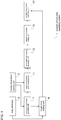
- FIG. 1 is a block diagram illustrating a schematic configuration of a possible arrival point specifying system 1 of one embodiment of the present invention.
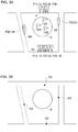
- the schematic diagrams illustrated in FIGS. 2 and 3 will be used for explanation below when necessary.
- the possible arrival point specifying system 1 of the first embodiment includes a map database 3, a probe information storing unit 5, a destination point group generating unit 7, a target area setting unit 9, a target link deviation point specifying unit 11, a link deviation point group generating unit 13, a reference coordinate setting unit 15 and a possible arrival point specifying unit 17.
- the map database 3 stores map data therein.
- the map data includes road-element-related information for defining map information, such as links and nodes, and other information that is drawn in a three-dimensional map, such as structures.
- map information such as links and nodes
- other information that is drawn in a three-dimensional map, such as structures.
- map data cities/wards/towns/villages, blocks, and building outlines may be stored in association with coordinates representing the respective area thereof.
- block polygon data indicating the area is stored for the block.
- building outline polygon data indicating the area is stored for the building outline.
- the probe information storing unit 5 stores therein the destination points set by the navigation system in association with the link deviation points corresponding to the respective destination points.
- link deviation points P11 to P15 are associated with the destination point D1.
- multiple link deviation points may be associated with the same destination point.
- the destination point include a coordinate of the destination that is set as a target of the route search by a route search unit (not shown) in the navigation system.
- the destination point may be set as the coordinate corresponding to the destination.
- the destination point When the destination is set by entering an address, the destination point may be set as a coordinate corresponding to the address.
- the database is referred to and the coordinate of the representative point corresponding to the facility name, the facility address, or the facility telephone number, which are entered during setting the destination, may be stored as the destination point.
- examples of the link deviation point corresponding to the set destination point include a point on a surrounding road that surrounds the area (e.g., a block), in which the set destination point is located.
- a vehicle which drives to the destination point as the destination, deviates from the surrounding road and enters the area.
- the examples of other information in the probe information include a vehicle ID for identifying a probe vehicle, coordinate information, time information, travel trajectory, direction, speed, acceleration, brake, hard brake, direction indicator, steering wheel angle, headlamp, and wiper.
- the destination point group generating unit 7 refers to the probe information storing unit 5 and groups the destination points located adjacent to each other to generate a destination point group.
- the method for generating the destination point group is not limited to any particular method.
- the destination points may be grouped, for example, based on an index, such as a distance between destination points, a block polygon, and a building outline polygon.
- the distance between the destination points is used as the index, for example, when there are a predetermined number (e.g., two or more) of the destination points located within a predetermined range (e.g., within an area defined by 100 m radius), the above multiple destination points located within the predetermined range may be grouped as the destination point group. For example, in FIG.
- destination points D1 to D3 located within a range a of 100 m radius may be grouped.
- the block polygon is used as the index
- the destination points located within the same block polygon may be grouped based on the block polygon data stored in the map database 3, for example.
- the destination points D1 to D4 located within the same block may be grouped as the destination point group in FIG. 2B .
- the building outline polygon is used as the index
- the destination points located within the same building outline polygon may be grouped based on the building outline polygon data stored in the map database 3.
- the target area setting unit 9 sets a target area based on the destination point group generated by the destination point group generating unit 7.
- the method for setting the target area is not limited to any particular method.
- the target area may correspond to the index used for generating the destination point group, such as the block polygon, the building outline polygon, and the range defined by the distance between destination points.
- the coordinates of all of the destination points included in the generated destination point group are used and a range of a minimum circle that includes all of the above destination points may be set as the target area.
- the range indicated by symbol A may be specified as the target area.
- the target link deviation point specifying unit 11 refers to the probe information storing unit 5 and specifies, as target link deviation points, link deviation points associated with the above destination points included in the destination point group generated by the destination point group generating unit 7.
- the target link deviation point specifying unit 11 may specify link deviation points P11 to P15, which are associated with a destination point D1, as the target link deviation points.
- the target link deviation point specifying unit 11 may specify link deviation points P21 to P26, which are associated with a destination point D2, as the target link deviation points.
- the target link deviation point specifying unit 11 may specify link deviation points P31 to P39, which are associated with a destination point D3, as the target link deviation points.
- the link deviation point group generating unit 13 groups the target link deviation points, which are specified by the target link deviation point specifying unit 11 and are located adjacent to each other, to generate a link deviation point group.
- the method for generating the link deviation point group is not limited to any particular method.
- target link deviation points which are located on the same link and which has a predetermined distance or less (e.g., 5 m or less) therebetween, may be grouped as the link deviation point group.
- link deviation point groups indicated by symbols G1 to G4 may be generated.
- the reference coordinate setting unit 15 sets a reference coordinate for the link deviation point group generated by the link deviation point group generating unit 13.
- the method for setting the reference coordinate is not limited to any particular method.
- the center of an approximate line formed based on the above link deviation point group may be set as the reference coordinate.
- the center of gravity of an area formed by connecting the outermost ones among the link deviation points within the link deviation point group may be set as the reference coordinate.
- the reference coordinates indicated by symbols Q1 to Q4 may be set.
- the possible arrival point specifying unit 17 specifies the reference coordinate set by the reference coordinate setting unit 15 as a possible arrival point of the above target area.
- the specified possible arrival point may be stored in a storing unit (not shown) in association with the corresponding target area.
- the storing unit is referred to when a destination is set in the navigation system. Therefore, the system may first specify the target area, in which the set destination is located, and may guide the vehicle to the possible arrival point associated with the specified target area.
- the system may provide, as the guidance, a possible arrival point closer to a current location of the vehicle indicated by the navigation system.
- the system may guide the vehicle to a possible arrival point having a minimum route cost computed based on Dijkstra's algorithm for a route between the possible arrival point and the current location of the vehicle.
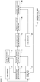
- FIG. 4 is a flowchart illustrating one example of a possible arrival point specifying method executed by the possible arrival point specifying system 1 illustrated in FIG. 1 .
- the destination point group generation unit 7 refers to the probe information storing unit 5 and groups the destination points located adjacent to each other to generate a destination point group.
- the destination points D1 to D3 located within the range indicated by symbol a are grouped to generate the destination point group.
- the diameter of the range indicated by symbol a is 100 m.
- the target area setting unit 9 sets the target area based on the destination point group generated at step 1.
- the range indicated by symbol A is set as the target area. More specifically, the minimum range defined based on the locations of the destination points in the destination point group generated at step 1 is set as the target area.
- the target link deviation point specifying unit 11 specifies, as the target link deviation points, the link deviation points associated with the destination point n included in the destination point group generated at step 1. Control iterates the processes at steps 5, 7 and 9 so that process at step 5 is executed for all the destination points included in the destination point group generated at step 1.
- control specifies the link deviation points P11 to P15, which are associated with the destination point D1, as the target link deviation points and specifies the link deviation points P21 to P26, which are associated with the destination point D2, as the target link deviation points.
- control specifies the link deviation points P31 to P39, which are associated with the destination point D3, as the target link deviation points.
- the link deviation point group generating unit 13 uses the target link deviation points, which are specified by the processes at steps 5 to 9, and groups the target link deviation points, which are located adjacent to each other, to generate the link deviation point group.
- the link deviation points located within a range of 5 m on the same link are grouped to generate the link deviation point groups G1 to G4.
- control sets the reference coordinates for the respective link deviation point groups generated at step 11.
- the reference coordinates indicated by symbols Q1 to Q4 are set for the link deviation point groups G1 to G4, respectively.
- the reference coordinate Q1 is positioned half way between the point P11, which is positioned at one end of the link deviation point group G1, and the point P39, which is positioned at the other end of the link deviation point group G1 that includes the link deviation points P11, P12, P25, P26, and P39.
- the possible arrival point specifying unit 17 specifies the reference coordinates set at step 13 as the possible arrival points of the target area set at step 3.
- the reference coordinates Q1 to Q4 are specified as the possible arrival points for the target area A.
- FIG. 5 is a block diagram illustrating a schematic configuration of a possible arrival point specifying system 21 of one embodiment of the present invention.
- the possible arrival point specifying system 21 of the second embodiment further includes a facility database 23 in addition to each component of the possible arrival point specifying system 1 of the first embodiment, and includes a possible arrival point specifying unit 25 to replace the possible arrival point specifying unit 17.
- a facility database 23 in addition to each component of the possible arrival point specifying system 1 of the first embodiment, and includes a possible arrival point specifying unit 25 to replace the possible arrival point specifying unit 17.
- FIG. 5 components similar to those in FIG. 1 are indicated by the same numerals and the explanation thereof will be partially omitted.
- the facility database 23 stores information on facilities therein. Examples of information on the facility include facility name, facility address, facility telephone number, and guidance end point. Each information is stored in association with a coordinate indicating the representative point of the facility, or with a polygon indicating the area of the facility.
- the above guidance end point corresponds to a point, at which the route guidance is ended, when the facility is set as the destination in the navigation system.
- the possible arrival point specifying unit 25 refers to the facility database 23 and specifies the reference coordinate set by the reference coordinate setting unit 15 as the possible arrival point of the facility located within the target area.
- Examples of a method for specifying the possible arrival point include specifying a facility having a facility address in the target area from the facility database 23, and specifying the above reference coordinate as a possible arrival point for the specified facility.
- the facility address may be replaced with a coordinate indicating the representative point of the facility, or with the polygon indicating the area of the facility, which are stored in the facility database 23.
- the specified possible arrival point may be stored in association with the corresponding facility included in the facility database 23.
- the facility database 23 is referred to when a destination is set in the navigation system.
- the system may specify a facility that matches the set destination and may provide, as the guidance, the possible arrival point associated with the specified facility instead of the guidance end point for the destination.
- the specified possible arrival point may be stored in a storing unit (not shown) in association with the corresponding facility.
- the possible arrival point specifying unit 25 functions similarly to the possible arrival point specifying unit 17.
- FIG. 6 is a block diagram illustrating a schematic configuration of a possible arrival point specifying system 31 of one embodiment of the present invention.
- the possible arrival point specifying system 31 of the third embodiment further includes the facility database 23 and a possible arrival point setting unit 33 in addition to each component of the possible arrival point specifying system 1 of the first embodiment.
- the possible arrival point specifying system 31 of the third embodiment further includes the facility database 23 and a possible arrival point setting unit 33 in addition to each component of the possible arrival point specifying system 1 of the first embodiment.
- components similar to those in FIGS. 1 and 5 are indicated by the same numerals and the explanation thereof will be partially omitted.
- the possible arrival point setting unit 33 sets the possible arrival point specified by the possible arrival point specifying unit 17 for other facilities having a predetermined relationship with the target area.
- the method for setting the possible arrival point is not limited to any particular method.
- a facility having a facility address located within a predetermined distance from the target area may be specified based on the facility database 23 and the above specified possible arrival point may be set for the specified facility.
- Examples of a method for specifying the possible arrival point include specifying a facility having a facility address located within the polygon (e.g., the block polygon, the building outline polygon), in which the above target area is located, based on the facility database 23, and setting the above possible arrival point for the specified facility.
- the facility address may be replaced with a coordinate indicating the representative point of the facility, or with the polygon indicating the area of the facility, which are stored in the facility database 23.
- FIG. 7 is a block diagram illustrating a schematic configuration of a possible arrival point specifying system 41 of one embodiment of the present invention.
- the possible arrival point specifying system 41 of the fourth embodiment further includes an evaluation unit 43 in addition to each component of the possible arrival point specifying system 1 of the first embodiment, and includes a possible arrival point specifying unit 45 to replace the possible arrival point specifying unit 17.
- an evaluation unit 43 in addition to each component of the possible arrival point specifying system 1 of the first embodiment, and includes a possible arrival point specifying unit 45 to replace the possible arrival point specifying unit 17.
- FIG. 7 components similar to those in FIGS. 1 , 5 and 6 are indicated by the same numerals and the explanation thereof will be partially omitted.
- the evaluation unit 43 evaluates the link deviation point group generated by the link deviation point group generating unit 13.
- the method for evaluating the link deviation point group is not limited to any particular method. Examples of evaluation include evaluating the link deviation point group based on the number of the link deviation points included in the link deviation point group or based on the distance from the link deviation point group to the destination. In an example of the former case, the link deviation point group having a larger number of link deviation points may be evaluated higher. For example, the link deviation point groups may be ranked in descending order of the number of link deviation points, and may be evaluated with multiple levels (e.g., 5 levels) based on the number of the link deviation points. In an example of the latter case, the link deviation point groups may be ranked higher when a distance from the destination is shorter and may be evaluated with multiple levels.
- the possible arrival point specifying unit 45 specifies the above possible arrival point based on the evaluation results by the evaluation unit 43.
- Examples of the method for specifying the possible arrival point include specifying the reference coordinate as the possible arrival point for the target area in consideration of the evaluation results.
- the reference coordinate of the link deviation point group that is evaluated highest among the evaluation results may be specified as the possible arrival point of the target area.
- FIG. 8 is a block diagram illustrating a schematic configuration of a possible arrival point specifying system 51 of one example embodiment of the present invention.
- the possible arrival point specifying system 51 according to the first example embodiment further includes a control unit 510, a memory unit 511, an input unit 512, an output unit 513, and an interface unit 514 in addition to the components that configure the possible arrival point specifying system 1 according to the first embodiment.
- the control unit 510 is a computer device, which includes a buffer memory and other devices, and the control unit 510 controls other components that configure the possible arrival point specifying system 51.
- the memory unit 511 stores therein a computer program, and the computer program is read by the control unit 510, which serves as the computer device, so that the control unit 510 functions accordingly.
- the computer program may be stored in a general medium such as an SD memory card TM .
- the input unit 512 is used by a user of the possible arrival point specifying system when the user inputs commands, for example.
- the input unit 512 may be a pointing device (e.g., a mouse, a light pen, a touch sensitive panel that works with content on a display), a keyboard, or an audio input device (e.g., a microphone).
- the output unit 513 includes a display.
- the output unit 513 may display the target area set by the target area setting unit 9, the reference coordinate set by the reference coordinate setting unit 15, the possible arrival point specified by the possible arrival point specifying unit 17, and the like together with a map.
- the interface unit 514 connects the possible arrival point specifying system 51 with a wireless network and the like.
- a possible arrival point specifying system a method for specifying a possible arrival point, and a tangible non-transitory computer-readable storage medium containing computer program are provided.
Landscapes
- Engineering & Computer Science (AREA)
- Radar, Positioning & Navigation (AREA)
- Remote Sensing (AREA)
- Automation & Control Theory (AREA)
- Physics & Mathematics (AREA)
- General Physics & Mathematics (AREA)
- Health & Medical Sciences (AREA)
- General Health & Medical Sciences (AREA)
- Social Psychology (AREA)
- Navigation (AREA)
- Instructional Devices (AREA)
- Traffic Control Systems (AREA)
Claims (12)
- System zum Spezifizieren eines möglichen Ankunftspunkt, mit:einer Sondeninformationenspeichereinheit (5), die konfiguriert ist, um darin durch ein Navigationssystem eingestellte Zielpunkte in Verbindung mit Verbindungsabweichungspunkten entsprechend den jeweiligen Zielpunkten zu speichern, wobei ein Verbindungsabweichungspunkt ein Punkt ist, an dem ein Fahrzeug von einer finalen Verbindung in einer Fahrttrajektorie zu einem entsprechenden eingestellten Zielpunkt abweicht;eine Zielpunktgruppenerzeugungseinheit (7), die konfiguriert ist, um sich auf die Sondeninformationenspeichereinheit (5) zu beziehen, und um die Zielpunkte, die sich benachbart zueinander befinden, zu gruppieren, um eine Zielpunktgruppe zu erzeugen;einer Zielbereichseinstelleinheit (9), die konfiguriert ist, um einen Zielbereich basierend auf der erzeugten Zielpunktgruppe einzustellen;einer Zielverbindungsabweichungspunktspezifizierungseinheit (11), die konfiguriert ist, um sich auf die Sondeninformationenspeichereinheit (5) zu beziehen, und um, als die Zielverbindungsabweichungspunkte, Verbindungsabweichungspunkte in Verbindung mit den in der erzeugten Zielpunktgruppe enthaltenen Zielpunkten zu spezifizieren;einer Verbindungsabweichungspunktgruppenerzeugungseinheit (13), die konfiguriert ist, um die spezifizierten Zielverbindungsabweichungspunkte, die sich benachbart zueinander befinden, zu gruppieren, um eine Verbindungsabweichungspunktgruppe zu erzeugen;einer Referenzkoordinateneinstelleinheit (15), die konfiguriert ist, um eine Referenzkoordinate für die erzeugte Verbindungsabweichungspunktgruppe einzustellen; undeiner Spezifizierungseinheit eines möglichen Ankunftspunkts (17), die konfiguriert ist, um die eingestellte Referenzkoordinate als einen möglichen Ankunftspunkt des Zielbereichs und/oder einen möglichen Ankunftspunkt einer Einrichtung oder einer Adresse, die sich innerhalb des Zielbereichs befindet, zu spezifizieren.
- System zum Spezifizieren eines möglichen Ankunftspunkts gemäß Anspruch 1, mit:
einer Einstelleinheit eines möglichen Ankunftspunkts (33), die konfiguriert ist, um den spezifizierten möglichen Ankunftspunkt auf eine andere Einrichtung mit einer vorbestimmten Beziehung mit dem Zielbereich einzustellen. - System zum Spezifizieren eines möglichen Ankunftspunkts gemäß Anspruch 2, wobei:
die vorbestimmte Beziehung auf einer Distanz, einem Gebäudeumriss oder einem Block basiert. - System zum Spezifizieren eines möglichen Ankunftspunkts gemäß einem der Ansprüche 1 bis 3, mit:
einer Evaluierungseinheit (43), die konfiguriert ist, um die erzeugte Verbindungsabweichungspunktgruppe zu evaluieren, wobei:
die Spezifizierungseinheit eines möglichen Ankunftspunkts (17) den möglichen Ankunftspunkt basierend auf einem Evaluierungsergebnis durch die Evaluierungseinheit (43) spezifiziert. - Verfahren zum Spezifizieren eines möglichen Ankunftspunkts, mit den Schritten:Speichern, in einer Sondeninformationenspeichereinheit (5), von durch ein Navigationssystem eingestellten Zielpunkten in Verbindung mit Verbindungsabweichungspunkten entsprechend den jeweiligen Zielpunkten, wobei ein Verbindungsabweichungspunkt ein Punkt ist, an dem ein Fahrzeug von einer finalen Verbindung in einer Fahrttrajektorie zu einem entsprechend eingestellten Zielpunkt abweicht;Bezugnehmen auf die Sondeninformationenspeichereinheit (5) und Gruppieren der Zielpunkte, die sich benachbart zueinander befinden, um eine Zielpunktgruppe zu erzeugen, unter Verwendung einer Zielpunktgruppenerzeugungseinheit (7);Einstellen eines Zielbereichs basierend auf der erzeugten Zielpunktegruppe unter Verwendung einer Zielbereichseinstelleinheit (9);Bezugnehmen auf die Sondeninformationenspeichereinheit (5) und Spezifizieren, als Zielverbindungsabweichungspunkte, von Verbindungsabweichungspunkten in Verbindung mit den in der erzeugten Zielpunktgruppe enthaltenen Zielpunkten unter Verwendung einer Zielverbindungsabweichungspunktspezifizierungseinheit (11);Gruppieren der spezifizierten Zielverbindungsabweichungspunkte, die sich benachbart zueinander befinden, um eine Verbindungsabweichungspunktgruppe zu erzeugen, unter Verwendung einer Verbindungsabweichungspunktgruppenerzeugungseinheit (13);Einstellen einer Referenzkoordinate für die erzeugte Verbindungsabweichungspunktgruppe unter Verwendung einer Referenzkoordinateneinstelleinheit (15); undSpezifizieren der eingestellten Referenzkoordinate als einen möglichen Ankunftspunkt des Zielbereichs und/oder eines möglichen Ankunftspunkts einer Einrichtung oder einer Adresse, die sich innerhalb des Zielbereichs befindet, unter Verwendung einer Spezifizierungseinheit eines möglichen Ankunftspunkts (17).
- Verfahren gemäß Anspruch 5, mit dem Schritt:
Einstellen des spezifizierten möglichen Ankunftspunkts auf eine andere Einrichtung mit einer vorbestimmten Beziehung mit dem Zielbereich unter Verwendung einer Einstelleinheit eines möglichen Ankunftspunkts (33). - Verfahren gemäß Anspruch 6, wobei:
die vorbestimmte Beziehung auf einer Distanz, einem Gebäudeumriss oder einem Block basiert. - Verfahren gemäß einem der Ansprüche 5 bis 7, mit dem Schritt:
Evaluieren der erzeugten Verbindungsabweichungspunktgruppe unter Verwendung einer Evaluierungseinheit (43) wobei:
das Spezifizieren des möglichen Ankunftspunkts ein Spezifizieren des möglichen Ankunftspunkts basierend auf einem Evaluierungsergebnis durch das Evaluieren der erzeugten Verbindungsabweichungspunktgruppe umfasst. - Materielles nichttransitorisches computerlesbares Speichermedium, das ein Computerprogramm zum Spezifizieren eines möglichen Ankunftspunkts enthält, wobei das Computerprogramm konfiguriert ist, um einen Computer zu veranlassen, zu fungieren als:eine Sondeninformationenspeichereinheit zum darin Speichern von durch ein Navigationssystem eingestellten Zielpunkten in Verbindung mit Verbindungsabweichungspunkten entsprechend den jeweiligen Zielpunkten, wobei ein Verbindungsabweichungspunkt ein Punkt ist, an dem ein Fahrzeug von einer finalen Verbindung in einer Fahrttrajektorie zu einem entsprechend eingestellten Zielpunkt abweicht;eine Zielpunktgruppenerzeugungseinrichtung zum Bezugnehmen auf die Sondeninformationenspeichereinheit und zum Gruppieren der sich benachbart zueinander befindlichen Zielpunkte, um eine Zielpunktgruppe zu erzeugen;eine Zielbereichseinstelleinrichtung zum Einstellen eines Zielbereichs basierend auf der erzeugten Zielpunktgruppe;eine Zielverbindungsabweichungspunktspezifizierungseinrichtung zum Bezugnehmen auf die Sondeninformationenspeichereinrichtung und zum Spezifizieren als Zielverbindungsabweichungspunkte, von Abweichungspunkten in Verbindung mit den in der erzeugten Zielpunktgruppe enthaltenen Zielpunkten;eine Verbindungsabweichungspunktgruppenerzeugungseinrichtung zum Gruppieren der spezifizierten Zielverbindungsabweichungspunkte, die sich benachbart zueinander befinden, um eine Verbindungsabweichungspunktgruppe zu erzeugen;eine Referenzkoordinateneinstelleinrichtung zum Einstellen einer Referenzkoordinate für die erzeugte Verbindungsabweichungspunktgruppe; undeine Spezifizierungseinrichtung eines möglichen Ankunftspunkts zum Spezifizieren der eingestellten Referenzkoordinate als einen möglichen Ankunftspunkt des Zielbereichs und/oder eines möglichen Ankunftspunkts einer Einrichtung oder einer Adresse, die sich innerhalb des Zielbereichs befindet.
- Materielles nichttransitorisches computerlesbares Speichermedium gemäß Anspruch 9, wobei das Computerprogramm weiterhin konfiguriert ist, um den Computer zu veranlassen zu fungieren als:
eine Einstelleinrichtung eines möglichen Ankunftspunkts zum Einstellen des spezifizierten möglichen Ankunftspunkts auf eine andere Einrichtung mit einer vorbestimmten Beziehung mit dem Zielbereich. - Materielles nichttransitorisches computerlesbares Speichermedium gemäß Anspruch 10, wobei:
die vorbestimmte Beziehung auf einer Distanz, einem Gebäudeumriss oder einem Block basiert. - Materielles nichttransitorisches computerlesbares Speichermedium gemäß einem der Ansprüche 9 bis 11, wobei das Computerprogramm weiterhin konfiguriert ist, um den Computer zu veranlassen zu fungieren als:
eine Evaluierungseinrichtung zum Evaluieren der erzeugten Verbindungsabweichungspunktgruppe, wobei:
die Spezifizierungseinrichtung eines möglichen Ankunftspunkts den möglichen Ankunftspunkt basierend auf einem Evaluierungsergebnis durch die Evaluierungseinrichtung spezifiziert.
Applications Claiming Priority (1)
| Application Number | Priority Date | Filing Date | Title |
|---|---|---|---|
| JP2017194047A JP6717792B2 (ja) | 2017-10-04 | 2017-10-04 | 候補到着地点特定装置、候補到着地点特定方法、コンピュータプログラム及びコンピュータプログラムを記録した記録媒体 |
Publications (2)
| Publication Number | Publication Date |
|---|---|
| EP3467440A1 EP3467440A1 (de) | 2019-04-10 |
| EP3467440B1 true EP3467440B1 (de) | 2021-12-15 |
Family
ID=61965752
Family Applications (1)
| Application Number | Title | Priority Date | Filing Date |
|---|---|---|---|
| EP18166484.8A Not-in-force EP3467440B1 (de) | 2017-10-04 | 2018-04-10 | System zur bestimmung eines möglichen zielpunkts, verfahren zur bestimmung eines möglichen zielpunkts und greifbares, nicht-transitorisches, computerlesbares speichermedium mit einem computerprogramm |
Country Status (4)
| Country | Link |
|---|---|
| US (1) | US20190101408A1 (de) |
| EP (1) | EP3467440B1 (de) |
| JP (1) | JP6717792B2 (de) |
| CN (1) | CN109612478A (de) |
Families Citing this family (1)
| Publication number | Priority date | Publication date | Assignee | Title |
|---|---|---|---|---|
| CN110892232A (zh) * | 2017-11-10 | 2020-03-17 | 宝马股份公司 | 用于智能地管理用户的多个潜在旅行目的地的方法和设备 |
Family Cites Families (10)
| Publication number | Priority date | Publication date | Assignee | Title |
|---|---|---|---|---|
| JP4072853B2 (ja) * | 2003-06-06 | 2008-04-09 | アルパイン株式会社 | ナビゲーション装置 |
| JP4644618B2 (ja) | 2006-03-24 | 2011-03-02 | パイオニア株式会社 | 位置登録装置、経路探索装置、位置登録方法、位置登録プログラムおよび記録媒体 |
| JP5368763B2 (ja) * | 2008-10-15 | 2013-12-18 | 株式会社ゼンリン | 電子地図整備システム |
| JP5437674B2 (ja) * | 2009-03-26 | 2014-03-12 | 株式会社トヨタマップマスター | 駐車場入口情報作成方法及びそのシステム、並びに駐車場入口情報を作成するためのコンピュータプログラム及びそのコンピュータプログラムを記録した記録媒体 |
| JP5741452B2 (ja) * | 2012-01-10 | 2015-07-01 | 株式会社デンソーアイティーラボラトリ | 車両用ナビゲーション装置 |
| JP2014102141A (ja) | 2012-11-20 | 2014-06-05 | Toyota Motor Corp | 経路情報処理装置、経路情報処理システム及び経路情報処理方法 |
| JP6094543B2 (ja) * | 2014-07-31 | 2017-03-15 | トヨタ自動車株式会社 | 出発地・目的地抽出装置、出発地・目的地抽出方法 |
| IL234323A0 (en) * | 2014-08-27 | 2014-11-30 | Parklife Ltd | Car navigation technology for a parking space |
| JP6515681B2 (ja) * | 2015-05-28 | 2019-05-22 | アイシン・エィ・ダブリュ株式会社 | 目的地取得システム、方法およびプログラム |
| US10317227B2 (en) * | 2017-11-07 | 2019-06-11 | Verizon Patent And Licensing Inc. | Routing to locations with multiple entrances |
-
2017
- 2017-10-04 JP JP2017194047A patent/JP6717792B2/ja active Active
-
2018
- 2018-04-02 CN CN201810282063.9A patent/CN109612478A/zh active Pending
- 2018-04-02 US US15/942,643 patent/US20190101408A1/en not_active Abandoned
- 2018-04-10 EP EP18166484.8A patent/EP3467440B1/de not_active Not-in-force
Non-Patent Citations (1)
| Title |
|---|
| None * |
Also Published As
| Publication number | Publication date |
|---|---|
| JP2019066404A (ja) | 2019-04-25 |
| EP3467440A1 (de) | 2019-04-10 |
| US20190101408A1 (en) | 2019-04-04 |
| CN109612478A (zh) | 2019-04-12 |
| JP6717792B2 (ja) | 2020-07-08 |
Similar Documents
| Publication | Publication Date | Title |
|---|---|---|
| CN110160552B (zh) | 导航信息确定方法、装置、设备和存储介质 | |
| US10137896B2 (en) | Method and system for operating autonomous driving vehicles using graph-based lane change guide | |
| JP6832421B2 (ja) | シミュレーションに基づく自動運転車の感知要求の評価方法 | |
| US10496098B2 (en) | Road segment-based routing guidance system for autonomous driving vehicles | |
| JP2022520902A (ja) | 速度計画方法、装置、電子機器および記憶媒体 | |
| CN108027243A (zh) | 用于操作自动驾驶车辆的控制误差校正规划方法 | |
| EP3327464A1 (de) | Algorithmus und infrastruktur für robuste und effiziente fahrzeuglokalisierung | |
| CN108602509A (zh) | 基于运动规划来操作自动驾驶车辆的方法和系统 | |
| EP2607852B1 (de) | Navigationsverfahren und -vorrichtungen mit verwendung benutzerspezifischer landmarkentypen | |
| CN109708656A (zh) | 基于实时路况的路线规划方法、系统、设备及存储介质 | |
| CN110325935A (zh) | 用于自动驾驶车辆的路径规划的基于驾驶场景的车道引导线 | |
| CN107209018A (zh) | 用于提供所关注点信息的方法及设备 | |
| JP2018531385A6 (ja) | 自律走行車を運行させるための制御エラー補正計画方法 | |
| CN114993335B (zh) | 一种自动驾驶路径规划方法、装置、电子设备及存储介质 | |
| CN114194217B (zh) | 车辆自动驾驶方法、装置、电子设备以及存储介质 | |
| CN106843219B (zh) | 无人驾驶车辆选择接泊点的方法、装置、设备及存储介质 | |
| CN104977009A (zh) | 使用空间及临时变量调度程序降低网络流量及计算负载 | |
| CN111316067B (zh) | 导航系统、导航方法 | |
| CN104677371B (zh) | 导航系统的路径搜索方法及其设备 | |
| JP2009204481A (ja) | ナビゲーション装置及びプログラム | |
| CN116088538B (zh) | 车辆轨迹信息生成方法、装置、设备和计算机可读介质 | |
| KR20220123861A (ko) | 차량 및 그 제어 방법 | |
| CN110109458A (zh) | 车载自动驾驶调度系统、方法、设备及存储介质 | |
| JP2010128838A (ja) | 入力デバイス | |
| EP3467440A1 (de) | System zur bestimmung eines möglichen zielpunkts, verfahren zur bestimmung eines möglichen zielpunkts und greifbares, nicht-transitorisches, computerlesbares speichermedium mit einem computerprogramm |
Legal Events
| Date | Code | Title | Description |
|---|---|---|---|
| PUAI | Public reference made under article 153(3) epc to a published international application that has entered the european phase |
Free format text: ORIGINAL CODE: 0009012 |
|
| STAA | Information on the status of an ep patent application or granted ep patent |
Free format text: STATUS: THE APPLICATION HAS BEEN PUBLISHED |
|
| AK | Designated contracting states |
Kind code of ref document: A1 Designated state(s): AL AT BE BG CH CY CZ DE DK EE ES FI FR GB GR HR HU IE IS IT LI LT LU LV MC MK MT NL NO PL PT RO RS SE SI SK SM TR |
|
| AX | Request for extension of the european patent |
Extension state: BA ME |
|
| STAA | Information on the status of an ep patent application or granted ep patent |
Free format text: STATUS: REQUEST FOR EXAMINATION WAS MADE |
|
| 17P | Request for examination filed |
Effective date: 20190430 |
|
| RBV | Designated contracting states (corrected) |
Designated state(s): AL AT BE BG CH CY CZ DE DK EE ES FI FR GB GR HR HU IE IS IT LI LT LU LV MC MK MT NL NO PL PT RO RS SE SI SK SM TR |
|
| STAA | Information on the status of an ep patent application or granted ep patent |
Free format text: STATUS: EXAMINATION IS IN PROGRESS |
|
| 17Q | First examination report despatched |
Effective date: 20200217 |
|
| GRAP | Despatch of communication of intention to grant a patent |
Free format text: ORIGINAL CODE: EPIDOSNIGR1 |
|
| STAA | Information on the status of an ep patent application or granted ep patent |
Free format text: STATUS: GRANT OF PATENT IS INTENDED |
|
| INTG | Intention to grant announced |
Effective date: 20210901 |
|
| RAP3 | Party data changed (applicant data changed or rights of an application transferred) |
Owner name: TOYOTA JIDOSHA KABUSHIKI KAISHA Owner name: TOYOTA MAPMASTER INCORPORATED |
|
| RIN1 | Information on inventor provided before grant (corrected) |
Inventor name: MATSUSHITA, MAKOTO Inventor name: DEGUCHI, SATORU |
|
| GRAS | Grant fee paid |
Free format text: ORIGINAL CODE: EPIDOSNIGR3 |
|
| GRAA | (expected) grant |
Free format text: ORIGINAL CODE: 0009210 |
|
| STAA | Information on the status of an ep patent application or granted ep patent |
Free format text: STATUS: THE PATENT HAS BEEN GRANTED |
|
| AK | Designated contracting states |
Kind code of ref document: B1 Designated state(s): AL AT BE BG CH CY CZ DE DK EE ES FI FR GB GR HR HU IE IS IT LI LT LU LV MC MK MT NL NO PL PT RO RS SE SI SK SM TR |
|
| REG | Reference to a national code |
Ref country code: GB Ref legal event code: FG4D Ref country code: CH Ref legal event code: EP |
|
| REG | Reference to a national code |
Ref country code: IE Ref legal event code: FG4D Ref country code: DE Ref legal event code: R096 Ref document number: 602018028083 Country of ref document: DE |
|
| REG | Reference to a national code |
Ref country code: AT Ref legal event code: REF Ref document number: 1455806 Country of ref document: AT Kind code of ref document: T Effective date: 20220115 |
|
| REG | Reference to a national code |
Ref country code: LT Ref legal event code: MG9D |
|
| REG | Reference to a national code |
Ref country code: NL Ref legal event code: MP Effective date: 20211215 |
|
| PG25 | Lapsed in a contracting state [announced via postgrant information from national office to epo] |
Ref country code: RS Free format text: LAPSE BECAUSE OF FAILURE TO SUBMIT A TRANSLATION OF THE DESCRIPTION OR TO PAY THE FEE WITHIN THE PRESCRIBED TIME-LIMIT Effective date: 20211215 Ref country code: LT Free format text: LAPSE BECAUSE OF FAILURE TO SUBMIT A TRANSLATION OF THE DESCRIPTION OR TO PAY THE FEE WITHIN THE PRESCRIBED TIME-LIMIT Effective date: 20211215 Ref country code: FI Free format text: LAPSE BECAUSE OF FAILURE TO SUBMIT A TRANSLATION OF THE DESCRIPTION OR TO PAY THE FEE WITHIN THE PRESCRIBED TIME-LIMIT Effective date: 20211215 Ref country code: BG Free format text: LAPSE BECAUSE OF FAILURE TO SUBMIT A TRANSLATION OF THE DESCRIPTION OR TO PAY THE FEE WITHIN THE PRESCRIBED TIME-LIMIT Effective date: 20220315 |
|
| PGFP | Annual fee paid to national office [announced via postgrant information from national office to epo] |
Ref country code: GB Payment date: 20220303 Year of fee payment: 5 |
|
| REG | Reference to a national code |
Ref country code: AT Ref legal event code: MK05 Ref document number: 1455806 Country of ref document: AT Kind code of ref document: T Effective date: 20211215 |
|
| PG25 | Lapsed in a contracting state [announced via postgrant information from national office to epo] |
Ref country code: SE Free format text: LAPSE BECAUSE OF FAILURE TO SUBMIT A TRANSLATION OF THE DESCRIPTION OR TO PAY THE FEE WITHIN THE PRESCRIBED TIME-LIMIT Effective date: 20211215 Ref country code: NO Free format text: LAPSE BECAUSE OF FAILURE TO SUBMIT A TRANSLATION OF THE DESCRIPTION OR TO PAY THE FEE WITHIN THE PRESCRIBED TIME-LIMIT Effective date: 20220315 Ref country code: LV Free format text: LAPSE BECAUSE OF FAILURE TO SUBMIT A TRANSLATION OF THE DESCRIPTION OR TO PAY THE FEE WITHIN THE PRESCRIBED TIME-LIMIT Effective date: 20211215 Ref country code: HR Free format text: LAPSE BECAUSE OF FAILURE TO SUBMIT A TRANSLATION OF THE DESCRIPTION OR TO PAY THE FEE WITHIN THE PRESCRIBED TIME-LIMIT Effective date: 20211215 Ref country code: GR Free format text: LAPSE BECAUSE OF FAILURE TO SUBMIT A TRANSLATION OF THE DESCRIPTION OR TO PAY THE FEE WITHIN THE PRESCRIBED TIME-LIMIT Effective date: 20220316 |
|
| PGFP | Annual fee paid to national office [announced via postgrant information from national office to epo] |
Ref country code: FR Payment date: 20220308 Year of fee payment: 5 |
|
| PG25 | Lapsed in a contracting state [announced via postgrant information from national office to epo] |
Ref country code: NL Free format text: LAPSE BECAUSE OF FAILURE TO SUBMIT A TRANSLATION OF THE DESCRIPTION OR TO PAY THE FEE WITHIN THE PRESCRIBED TIME-LIMIT Effective date: 20211215 |
|
| PG25 | Lapsed in a contracting state [announced via postgrant information from national office to epo] |
Ref country code: SM Free format text: LAPSE BECAUSE OF FAILURE TO SUBMIT A TRANSLATION OF THE DESCRIPTION OR TO PAY THE FEE WITHIN THE PRESCRIBED TIME-LIMIT Effective date: 20211215 Ref country code: SK Free format text: LAPSE BECAUSE OF FAILURE TO SUBMIT A TRANSLATION OF THE DESCRIPTION OR TO PAY THE FEE WITHIN THE PRESCRIBED TIME-LIMIT Effective date: 20211215 Ref country code: RO Free format text: LAPSE BECAUSE OF FAILURE TO SUBMIT A TRANSLATION OF THE DESCRIPTION OR TO PAY THE FEE WITHIN THE PRESCRIBED TIME-LIMIT Effective date: 20211215 Ref country code: PT Free format text: LAPSE BECAUSE OF FAILURE TO SUBMIT A TRANSLATION OF THE DESCRIPTION OR TO PAY THE FEE WITHIN THE PRESCRIBED TIME-LIMIT Effective date: 20220418 Ref country code: ES Free format text: LAPSE BECAUSE OF FAILURE TO SUBMIT A TRANSLATION OF THE DESCRIPTION OR TO PAY THE FEE WITHIN THE PRESCRIBED TIME-LIMIT Effective date: 20211215 Ref country code: EE Free format text: LAPSE BECAUSE OF FAILURE TO SUBMIT A TRANSLATION OF THE DESCRIPTION OR TO PAY THE FEE WITHIN THE PRESCRIBED TIME-LIMIT Effective date: 20211215 Ref country code: CZ Free format text: LAPSE BECAUSE OF FAILURE TO SUBMIT A TRANSLATION OF THE DESCRIPTION OR TO PAY THE FEE WITHIN THE PRESCRIBED TIME-LIMIT Effective date: 20211215 |
|
| PGFP | Annual fee paid to national office [announced via postgrant information from national office to epo] |
Ref country code: DE Payment date: 20220302 Year of fee payment: 5 |
|
| PG25 | Lapsed in a contracting state [announced via postgrant information from national office to epo] |
Ref country code: PL Free format text: LAPSE BECAUSE OF FAILURE TO SUBMIT A TRANSLATION OF THE DESCRIPTION OR TO PAY THE FEE WITHIN THE PRESCRIBED TIME-LIMIT Effective date: 20211215 Ref country code: AT Free format text: LAPSE BECAUSE OF FAILURE TO SUBMIT A TRANSLATION OF THE DESCRIPTION OR TO PAY THE FEE WITHIN THE PRESCRIBED TIME-LIMIT Effective date: 20211215 |
|
| REG | Reference to a national code |
Ref country code: DE Ref legal event code: R097 Ref document number: 602018028083 Country of ref document: DE |
|
| PG25 | Lapsed in a contracting state [announced via postgrant information from national office to epo] |
Ref country code: IS Free format text: LAPSE BECAUSE OF FAILURE TO SUBMIT A TRANSLATION OF THE DESCRIPTION OR TO PAY THE FEE WITHIN THE PRESCRIBED TIME-LIMIT Effective date: 20220415 |
|
| PLBE | No opposition filed within time limit |
Free format text: ORIGINAL CODE: 0009261 |
|
| STAA | Information on the status of an ep patent application or granted ep patent |
Free format text: STATUS: NO OPPOSITION FILED WITHIN TIME LIMIT |
|
| PG25 | Lapsed in a contracting state [announced via postgrant information from national office to epo] |
Ref country code: DK Free format text: LAPSE BECAUSE OF FAILURE TO SUBMIT A TRANSLATION OF THE DESCRIPTION OR TO PAY THE FEE WITHIN THE PRESCRIBED TIME-LIMIT Effective date: 20211215 Ref country code: AL Free format text: LAPSE BECAUSE OF FAILURE TO SUBMIT A TRANSLATION OF THE DESCRIPTION OR TO PAY THE FEE WITHIN THE PRESCRIBED TIME-LIMIT Effective date: 20211215 |
|
| 26N | No opposition filed |
Effective date: 20220916 |
|
| PG25 | Lapsed in a contracting state [announced via postgrant information from national office to epo] |
Ref country code: SI Free format text: LAPSE BECAUSE OF FAILURE TO SUBMIT A TRANSLATION OF THE DESCRIPTION OR TO PAY THE FEE WITHIN THE PRESCRIBED TIME-LIMIT Effective date: 20211215 |
|
| REG | Reference to a national code |
Ref country code: CH Ref legal event code: PL |
|
| REG | Reference to a national code |
Ref country code: BE Ref legal event code: MM Effective date: 20220430 |
|
| PG25 | Lapsed in a contracting state [announced via postgrant information from national office to epo] |
Ref country code: MC Free format text: LAPSE BECAUSE OF FAILURE TO SUBMIT A TRANSLATION OF THE DESCRIPTION OR TO PAY THE FEE WITHIN THE PRESCRIBED TIME-LIMIT Effective date: 20211215 Ref country code: LU Free format text: LAPSE BECAUSE OF NON-PAYMENT OF DUE FEES Effective date: 20220410 Ref country code: LI Free format text: LAPSE BECAUSE OF NON-PAYMENT OF DUE FEES Effective date: 20220430 Ref country code: CH Free format text: LAPSE BECAUSE OF NON-PAYMENT OF DUE FEES Effective date: 20220430 |
|
| PG25 | Lapsed in a contracting state [announced via postgrant information from national office to epo] |
Ref country code: BE Free format text: LAPSE BECAUSE OF NON-PAYMENT OF DUE FEES Effective date: 20220430 |
|
| PG25 | Lapsed in a contracting state [announced via postgrant information from national office to epo] |
Ref country code: IE Free format text: LAPSE BECAUSE OF NON-PAYMENT OF DUE FEES Effective date: 20220410 |
|
| PG25 | Lapsed in a contracting state [announced via postgrant information from national office to epo] |
Ref country code: IT Free format text: LAPSE BECAUSE OF FAILURE TO SUBMIT A TRANSLATION OF THE DESCRIPTION OR TO PAY THE FEE WITHIN THE PRESCRIBED TIME-LIMIT Effective date: 20211215 |
|
| REG | Reference to a national code |
Ref country code: DE Ref legal event code: R119 Ref document number: 602018028083 Country of ref document: DE |
|
| GBPC | Gb: european patent ceased through non-payment of renewal fee |
Effective date: 20230410 |
|
| PG25 | Lapsed in a contracting state [announced via postgrant information from national office to epo] |
Ref country code: GB Free format text: LAPSE BECAUSE OF NON-PAYMENT OF DUE FEES Effective date: 20230410 |
|
| PG25 | Lapsed in a contracting state [announced via postgrant information from national office to epo] |
Ref country code: GB Free format text: LAPSE BECAUSE OF NON-PAYMENT OF DUE FEES Effective date: 20230410 Ref country code: FR Free format text: LAPSE BECAUSE OF NON-PAYMENT OF DUE FEES Effective date: 20230430 Ref country code: DE Free format text: LAPSE BECAUSE OF NON-PAYMENT OF DUE FEES Effective date: 20231103 |
|
| PG25 | Lapsed in a contracting state [announced via postgrant information from national office to epo] |
Ref country code: HU Free format text: LAPSE BECAUSE OF FAILURE TO SUBMIT A TRANSLATION OF THE DESCRIPTION OR TO PAY THE FEE WITHIN THE PRESCRIBED TIME-LIMIT; INVALID AB INITIO Effective date: 20180410 |
|
| PG25 | Lapsed in a contracting state [announced via postgrant information from national office to epo] |
Ref country code: MK Free format text: LAPSE BECAUSE OF FAILURE TO SUBMIT A TRANSLATION OF THE DESCRIPTION OR TO PAY THE FEE WITHIN THE PRESCRIBED TIME-LIMIT Effective date: 20211215 Ref country code: CY Free format text: LAPSE BECAUSE OF FAILURE TO SUBMIT A TRANSLATION OF THE DESCRIPTION OR TO PAY THE FEE WITHIN THE PRESCRIBED TIME-LIMIT Effective date: 20211215 |
|
| PG25 | Lapsed in a contracting state [announced via postgrant information from national office to epo] |
Ref country code: TR Free format text: LAPSE BECAUSE OF FAILURE TO SUBMIT A TRANSLATION OF THE DESCRIPTION OR TO PAY THE FEE WITHIN THE PRESCRIBED TIME-LIMIT Effective date: 20211215 |
|
| PG25 | Lapsed in a contracting state [announced via postgrant information from national office to epo] |
Ref country code: MT Free format text: LAPSE BECAUSE OF FAILURE TO SUBMIT A TRANSLATION OF THE DESCRIPTION OR TO PAY THE FEE WITHIN THE PRESCRIBED TIME-LIMIT Effective date: 20211215 |