EP3466642A1 - Vorrichtung und verfahren zum aufwickeln eines materialstreifens - Google Patents
Vorrichtung und verfahren zum aufwickeln eines materialstreifens Download PDFInfo
- Publication number
- EP3466642A1 EP3466642A1 EP17195223.7A EP17195223A EP3466642A1 EP 3466642 A1 EP3466642 A1 EP 3466642A1 EP 17195223 A EP17195223 A EP 17195223A EP 3466642 A1 EP3466642 A1 EP 3466642A1
- Authority
- EP
- European Patent Office
- Prior art keywords
- winding
- strip
- axial direction
- winding shaft
- mandrel
- Prior art date
- Legal status (The legal status is an assumption and is not a legal conclusion. Google has not performed a legal analysis and makes no representation as to the accuracy of the status listed.)
- Granted
Links
Images



Classifications
-
- B—PERFORMING OPERATIONS; TRANSPORTING
- B29—WORKING OF PLASTICS; WORKING OF SUBSTANCES IN A PLASTIC STATE IN GENERAL
- B29C—SHAPING OR JOINING OF PLASTICS; SHAPING OF MATERIAL IN A PLASTIC STATE, NOT OTHERWISE PROVIDED FOR; AFTER-TREATMENT OF THE SHAPED PRODUCTS, e.g. REPAIRING
- B29C53/00—Shaping by bending, folding, twisting, straightening or flattening; Apparatus therefor
- B29C53/56—Winding and joining, e.g. winding spirally
- B29C53/58—Winding and joining, e.g. winding spirally helically
- B29C53/60—Winding and joining, e.g. winding spirally helically using internal forming surfaces, e.g. mandrels
- B29C53/62—Winding and joining, e.g. winding spirally helically using internal forming surfaces, e.g. mandrels rotatable about the winding axis
- B29C53/64—Winding and joining, e.g. winding spirally helically using internal forming surfaces, e.g. mandrels rotatable about the winding axis and moving axially
-
- B—PERFORMING OPERATIONS; TRANSPORTING
- B29—WORKING OF PLASTICS; WORKING OF SUBSTANCES IN A PLASTIC STATE IN GENERAL
- B29C—SHAPING OR JOINING OF PLASTICS; SHAPING OF MATERIAL IN A PLASTIC STATE, NOT OTHERWISE PROVIDED FOR; AFTER-TREATMENT OF THE SHAPED PRODUCTS, e.g. REPAIRING
- B29C53/00—Shaping by bending, folding, twisting, straightening or flattening; Apparatus therefor
- B29C53/32—Coiling
-
- B—PERFORMING OPERATIONS; TRANSPORTING
- B29—WORKING OF PLASTICS; WORKING OF SUBSTANCES IN A PLASTIC STATE IN GENERAL
- B29C—SHAPING OR JOINING OF PLASTICS; SHAPING OF MATERIAL IN A PLASTIC STATE, NOT OTHERWISE PROVIDED FOR; AFTER-TREATMENT OF THE SHAPED PRODUCTS, e.g. REPAIRING
- B29C53/00—Shaping by bending, folding, twisting, straightening or flattening; Apparatus therefor
- B29C53/56—Winding and joining, e.g. winding spirally
- B29C53/58—Winding and joining, e.g. winding spirally helically
- B29C53/581—Winding and joining, e.g. winding spirally helically using sheets or strips consisting principally of plastics material
-
- B—PERFORMING OPERATIONS; TRANSPORTING
- B29—WORKING OF PLASTICS; WORKING OF SUBSTANCES IN A PLASTIC STATE IN GENERAL
- B29C—SHAPING OR JOINING OF PLASTICS; SHAPING OF MATERIAL IN A PLASTIC STATE, NOT OTHERWISE PROVIDED FOR; AFTER-TREATMENT OF THE SHAPED PRODUCTS, e.g. REPAIRING
- B29C53/00—Shaping by bending, folding, twisting, straightening or flattening; Apparatus therefor
- B29C53/56—Winding and joining, e.g. winding spirally
- B29C53/58—Winding and joining, e.g. winding spirally helically
- B29C53/60—Winding and joining, e.g. winding spirally helically using internal forming surfaces, e.g. mandrels
- B29C53/62—Winding and joining, e.g. winding spirally helically using internal forming surfaces, e.g. mandrels rotatable about the winding axis
-
- B—PERFORMING OPERATIONS; TRANSPORTING
- B29—WORKING OF PLASTICS; WORKING OF SUBSTANCES IN A PLASTIC STATE IN GENERAL
- B29C—SHAPING OR JOINING OF PLASTICS; SHAPING OF MATERIAL IN A PLASTIC STATE, NOT OTHERWISE PROVIDED FOR; AFTER-TREATMENT OF THE SHAPED PRODUCTS, e.g. REPAIRING
- B29C53/00—Shaping by bending, folding, twisting, straightening or flattening; Apparatus therefor
- B29C53/80—Component parts, details or accessories; Auxiliary operations
- B29C53/82—Cores or mandrels
- B29C53/821—Mandrels especially adapted for winding and joining
-
- B—PERFORMING OPERATIONS; TRANSPORTING
- B32—LAYERED PRODUCTS
- B32B—LAYERED PRODUCTS, i.e. PRODUCTS BUILT-UP OF STRATA OF FLAT OR NON-FLAT, e.g. CELLULAR OR HONEYCOMB, FORM
- B32B43/00—Operations specially adapted for layered products and not otherwise provided for, e.g. repairing; Apparatus therefor
-
- B—PERFORMING OPERATIONS; TRANSPORTING
- B65—CONVEYING; PACKING; STORING; HANDLING THIN OR FILAMENTARY MATERIAL
- B65H—HANDLING THIN OR FILAMENTARY MATERIAL, e.g. SHEETS, WEBS, CABLES
- B65H18/00—Winding webs
- B65H18/28—Wound package of webs
Definitions
- the invention relates to a device and a method for winding a material strip, in particular a plastic film or a multilayer plastic laminate.
- a winding mandrel is provided, which is rotatably driven about an axis of rotation extending in a longitudinal direction.
- a strip of material is generally an object to understand, which has very different dimensions in a thickness in a width and in a longitudinal direction. Between the dimensions are usually one or more orders of magnitude, wherein the thickness has the smallest extent and the length has the largest extent.
- the thickness usually ranges from about 10 microns for single-layer plastic films up to a few millimeters (about 2 mm) for particularly elaborate ruffled or wrinkled laminates.
- the width of a corresponding material strip is usually at least 10 times, preferably at least 1000 times the thickness.
- the width of such material webs is - depending on the purpose and production step - between a few centimeters and about 2 m.
- the length of the material strip in turn is at least 10 times its width, preferably at least 100 times.
- Material strips can easily reach lengths of several 100 m to several 1000 m and fed batchwise or in continuous production of the material strip also "endless". With conventional Devices and methods can only be stably wound coils with strip lengths of about 1000 to 1500 meters.
- the device according to the invention and the method according to the invention are particularly suitable for strips of material made of a plastic material.
- a plastic material This may be, for example, a single-layer or multi-layer plastic film. These usually have a thickness of between 10 .mu.m (in a monofilm) up to several 100 .mu.m in multilayer (coextrusion) films.
- the method according to the invention and the device according to the invention can be used particularly well with strip widths of between about 1 cm and 20 cm.
- the inventive method and apparatus of the invention are very well.
- These may be, in particular, elastic multilayer laminates which have an elastic film layer and at least one nonwoven layer laminated thereon.
- the known devices in the process are only insufficiently suitable for narrow plastic strips, in particular with a width of less than 30 cm.
- Corresponding material widths are z. B. achieved in intermediate products for example for the production of so-called diaper ears. Even with an axially oscillating winding only a few layers can be wound up, since the coil thus produced is due to an unfavorable ratio between the radial to the axial extent very unstable sitting on the role.
- the invention has for its object to simplify the construction of a winding material strips, in particular plastic laminates, with the possibility of axial displacement. Furthermore, it is the object of the invention to provide an improved winding method for material webs, in particular plastic laminates, which makes use of the advantages of the winding device according to the invention.
- the generic device for winding a strip of material has a rotatable about an axis of rotation extending in an axial direction driven mandrel on.
- a winding shaft is arranged on the winding mandrel, which is rotatably coupled to the winding mandrel and slidable in the axial direction.
- One end of the material strip is connected directly or indirectly to the winding shaft, so that upon rotation of the winding mandrel, which is transferred to the winding shaft, several layers of the material strip are rolled up into a coil.
- the coil follows an axial displacement of the winding shaft, so that subsequent material of the strip is deposited with offset.
- the inventive design of the rotary drive and the axial displaceability are mechanically decoupled.
- a conventional winding mandrel of a machine can be used in which an axial displacement was previously not provided.
- a particularly simple retrofitting is possible.
- the mandrel is preferably continuous. It spans the entire area in which the strip of material is supplied and is, preferably end, held rotatably on the winding device with two bearing arrangements. Conveniently, the winding mandrel is designed as a solid shaft.
- the winding shaft arranged axially displaceably on the winding mandrel forms, at least in sections, a sleeve-shaped hollow shaft.
- the winding shaft is dimensioned in the axial direction so that it permits an axial displacement of at least 1.5 times, preferably by at least 2 times, in particular by 10 times, the width of the material strip.
- the axial extent of the winding shaft is at most 75% of the axial distance between the bearing assemblies for rotatable mounting with the winding mandrel on the winding device.
- the rotationally fixed coupling between the winding mandrel and the winding shaft via at least one axially extending tongue and groove connection is realized.
- the tongue and groove connection is realized by a running in the cylindrical outer surface of the winding mandrel, oriented in the axial direction of the groove and a hierein engaging projection of the winding shaft.
- a mechanical reversal or the use of a feather key is possible.
- the winding shaft is positively held on the outside of the winding mandrel and thereby rotatably connected thereto. However, due to the course of the groove in the axial direction, the winding shaft remains displaceable in this direction.
- a plurality of tongue and groove connections between the winding shaft and the winding mandrel can be arranged. These are expediently arranged equidistantly on the outer peripheral surface of the winding mandrel.
- the winding shaft is displaceably formed on the winding mandrel by an electric or hydraulic drive.
- this can also be arranged co-rotating between the winding mandrel and the winding shaft.
- the winding shaft has a circumferential groove, in which a driver for moving the longitudinal device intervenes.
- the circumferential groove is arranged on a cylindrical outer portion of the winding shaft and extends in a plane perpendicular to the axis of rotation.
- the circumferential groove is arranged in an end region of the winding shaft in the axial direction.
- the end region with the groove can in particular be designed as a separate extension, which is connected to the main part of the winding shaft axially rigid but rotatably movable.
- the main part of the winding shaft has an outer portion, on which the material strip or a separate winding body is held.
- a bearing may be formed between the extension and the winding mandrel.
- This bearing can be designed as a plain slide bearing or as a rolling bearing.
- the rolling bearing must be designed so that it tolerates an axial displacement relative to the winding mandrel.
- the connection between the extension and the main part of the winding shaft is expediently realized via a rolling bearing, for example a deep groove ball bearing.
- the driver is movable via an external, preferably electric or hydraulic drive in the axial direction.
- the winding shaft is removable via a shaft end.
- the winding shaft including the windings rolled up on it, can be removed after completion of the winding process.
- the winding shaft fastening means for one or more winding body in particular in the form of a paperboard roll, respectively.
- the winding body is thereby held concentrically around the axis of rotation of the winding shaft.
- the winding body is expediently braced radially on the inside with the winding shaft or axially on the outside. This has the advantage that the winding is not carried out directly on the winding shaft, but on the winding body, which can be removed after completion of the winding process as a whole including coiled webs of material.
- the invention also provides a method for winding a material strip through a device according to one of the preceding claims.
- a strip of material preferably endless, fed, whose end is coupled to the winding shaft.
- the end region of the material strip is therefore connected directly or indirectly to an outer surface of the winding shaft, so that a rotational movement and an axial displacement of the winding shaft are transmitted to the end region of the material strip or layers of the material strip already wound thereon.
- the winding mandrel and the winding shaft according to the invention are offset by a drive in a rotational movement to wind the strip of material directly or indirectly on the winding shaft. During the turning operation, the winding shaft is moved relative to the winding mandrel in the axial direction.
- the axial displacement allows a more uniform distribution of the material strip.
- the axial displaceability is realized particularly advantageously via an axially displaceable winding shaft.
- the displacement in the axial direction is intermittent. During the winding process, there are therefore phases and phases without an axial movement of the winding shaft opposite the mandrel. Particularly preferably, the axial movement takes place in cycles as a function of the number of turns made the winding roller.
- first a first number of layers of the material strip is wound at a first position relative to the axial direction. Subsequently, a shift takes place by a first distance. Subsequently, the winding takes place at a second position relative to the axial direction.
- the first distance corresponds at least to the stripe width. It is preferably 1.5 times, in particular at least twice the strip width.
- the amplitude of the axial movement is greater than the width of the strip of material.
- the layers wound up at the second position are independent of those which are wound up at the first position. In between, there is only one material strip connecting the two layers, which is arranged helically as a result of the superposition of the rotational movement with the axial movement.
- the axial travel speed is chosen in particular so that the material strip does not overlap with itself in the connecting section.
- the first position is preferably located on a first edge of the bobbin in the axial direction and the second position on a second edge of the bobbin in the axial direction.
- the distance of the material strip to one edge of the winding body is less than the width of the material strip.
- the axial travel must be at least the simple width of the strip.
- a second number of layers of the material strip are wound at the second position with respect to the axial direction. Subsequently, a further displacement takes place by a second distance, so that the strip of material is subsequently wound up at a third position with respect to the axial direction.
- the second distance is also at least 1-fold, preferably 1.5 times, in particular at least 2 times the strip width.
- the second distance has the same amount but the opposite direction of the first distance.
- the third position is identical to the first position.
- the winding of the material strip is thus effectively (except for the connecting areas) exclusively at the first and at the second position.
- the layers of the material strip are evenly distributed to the first position and the second position, which is particularly advantageous for the stability of the bobbin on the winding roller.
- a distribution of the winding to a plurality of positions relative to the axial direction may be advantageous.
- the first position and the second position are approached several times in succession.
- the connecting sections occurring in each case surprisingly can make a significant contribution to the stability of the two, despite their low cost of materials achieve interconnected coils compared to two separate coils.
- the strip material can also be distributed to more than two positions.
- the winding is controlled so that at all positions always similar many layers are wound up.
- the Fig. 1 shows a device according to the invention 1. This is provided for winding at least one strip of material 2.
- two strips of material 2 are fed in parallel via a contact roller 3.
- the two strips of material 2 have an identical width b and are supplied at a distance d of at least twice the width b, preferably at least 2.2 times the width.
- the device 1 has a winding mandrel 4 which is rotatably driven about an axis of rotation extending in an axial direction x.
- the drive 5 for generating the rotational movement of the winding mandrel 4 is indicated only schematically.
- the winding mandrel and the drive are arranged fixedly along the axial direction x.
- the mandrel is formed continuously and spans in the axial direction x at least one area between a first bearing 6a and a second bearing 6b.
- the bearing points 6a and 6b are arranged on both sides of the feed roller 3.
- a winding shaft 7 is arranged on the winding mandrel 4, which is rotatably coupled to the winding mandrel and in the axial direction x is displaceable.
- two bobbins 8 are each arranged to receive the windings of a strip of material 2.
- the winding body 8 are formed by cardboard rolls, which on the inside with the Winding shaft 7 are radially braced.
- the Fig. 1 represents the phase at the beginning of the winding process, in which no complete winding layers are still applied to the winding body 8. Only the end of the material strip 2 is already attached to the winding bodies 8.
- an electric drive 9 which acts by means of a driver 10 on a groove 7a on an extension 7b of the winding shaft 7.
- the driver 10 is also designed as a support, which carries the mandrel 4 in addition to the two bearing elements 6a and 6b.
- the mandrel 4 is formed as a solid shaft, which has at their ends thickenings for the bearing assemblies 6a, 6b.
- the multi-part winding shaft 7 is arranged.
- the winding shaft 7 comprises an outer portion 7c, on which the winding body 8 can be fastened with fastening means, not shown.
- a flange-like end 7d can be seen.
- a projection 7 e is arranged, which engages in an associated groove 4 a of the winding mandrel 4.
- a single tongue and groove connection is provided consisting of the groove 4a and the projection 7e.
- FIG. 2A Right end shown the tubular extension 7b of the winding shaft 7, which surrounds the winding mandrel 4 concentrically and with a small distance.
- the extension 7b On the extension 7b are two circumferentially extending circumferential grooves 7a to interact with the Driver 10 provided.
- the contact surface between the extension 7b and the mandrel 4 is formed as a simple sliding bearing, which allows both a translational movement in the axial direction and a relative rotational movement about the axis of rotation.
- the connection between the outer portion 7c and the projection 7a of the extension 7b is formed by means of a rolling bearing 7f.
- the rolling bearing 7f allows relative rotational movement about the rotation axis, while the extension 7b and the outer portion 7c are fixedly coupled to each other in the axial direction. This allows a smaller or vanishing relative rotational movement between the extension 7b and the driver 10 and thus reduces wear.
- the method according to the invention for winding up a material strip will be explained below.
- the two bobbin 8 are still empty and only the ends of the strip of material 2 connected to the bobbins 8.
- the winding shaft 7 is located in a first position with respect to the axial direction x, from which it is shifted so far to the right that the strips of material 2 near the left end of the winding body 8 are brought to this.
- the winding mandrel 4 is set in a rotational movement, which is transmitted to the winding body 8 via the winding shaft 7.
- the strips of material 2 are wound on the winding bodies 8. It forms without axial movement of the winding shaft 7, first a coil 11 consisting of several layers of the material strip 2 at the first position. This is in Fig. 3A shown. Outside the first position is still no part of the material strip 2 on the bobbins 8.
- the winding shaft When a first number of windings is reached at the first position, the winding shaft is axially displaced while the rotary movement is in progress. How one Fig. 3B takes, the axial travel speed is chosen so that within a revolution of the travel in the axial direction x is greater than the width b of the strip of material 2. As a result, the strip of material 2 is wound helically and without overlap on the bobbin 8.
- Fig. 3B reaches the strip of material with respect to the axial direction x a second position in relation to the winding shaft 7.
- the strip of material is now wound in the second position near the right end of the bobbin 8.
- the axial distance between the first position and the second position is at least 2 times the strip width b.
- the winding shaft moves in the reverse direction by the same amount a, so that the strips of material 2 are now wound up again at the first position.
- Fig. 4A represented in the entirety of the device 1.
- the two strips of material are each co-wound on separate bobbins 8.
- the change between the first position and the second position can be like the one Fig. 4B removes, repeated several times in succession. This results in a much more stable winding on the winding bodies than if the same material were statically wound up in only one position.
Landscapes
- Engineering & Computer Science (AREA)
- Mechanical Engineering (AREA)
- Winding Of Webs (AREA)
Abstract
Description
- Die Erfindung betrifft eine Vorrichtung und ein Verfahren zum Aufwickeln eines Materialstreifens, insbesondere einer Kunststofffolie oder eines mehrschichtigen Kunststofflaminats. Hierzu ist ein Wickeldorn vorgesehen, welche um eine in einer Längsrichtung verlaufende Drehachse drehbar angetrieben ist.
- Unter einem Materialstreifen ist allgemein ein Objekt zu verstehen, welches sehr unterschiedliche Abmessungen in einer Dicken- in einer Breiten- sowie in einer Längsrichtung aufweist. Zwischen den Abmessungen liegen üblicherweise ein oder mehrere Größenordnungen, wobei die Dicke die geringste Ausdehnung und die Länge die größte Ausdehnung aufweist.
- Bei Kunststofffolien und Kunststofflaminaten, auf die sich die Erfindung im Besonderen bezieht, reicht die Dicke üblicherweise zwischen etwa 10 µm bei einlagigen Kunststofffolien bis zu einigen Millimetern (etwa 2 mm) bei besonders aufwendigen Laminaten mit Rüschen- bzw. Faltenbildung. Die Breite eines entsprechenden Materialstreifens liegt üblicherweise zumindest bei dem 10-Fachen vorzugsweise zumindest beim 1000-Fachen der Dicke.
- Die Breite solcher Materialbahnen beträgt dabei -je nach Anwendungszweck und Produktionsschritt - zwischen einigen wenigen Zentimetern und ca. 2 m. Die Länge des Materialstreifens wiederum liegt zumindest beim 10-Fachen von dessen Breite, vorzugsweise zumindest beim 100-Fachen.
- Materialstreifen können ohne weiteres Längen von mehreren 100 m bis einige 1000 m erreichen und batchweise bzw. bei kontinuierlicher Produktion des Materialstreifens auch "endlos" zugeführt werden. Mit herkömmlichen Vorrichtungen und Verfahren können lediglich Spulen mit Streifenlängen von ca. 1000 bis 1500 Metern stabil aufgespult werden.
- Die erfindungsgemäße Vorrichtung sowie das erfindungsgemäße Verfahren eignen sich besonders gut für Materialstreifen aus einem Kunststoffmaterial. Hierbei kann es sich beispielsweise um eine ein- oder mehrschichtige Kunststofffolie handeln. Diese weisen üblicherweise eine Dicke zwischen 10 µm (bei einer Monofolie) bis zu mehreren 100 µm bei mehrschichtigen (Coextrusions-)Folien auf. Besonders gut sind das erfindungsgemäße Verfahren und die erfindungsgemäße Vorrichtung bei Streifenbreiten zwischen ca. 1 cm und 20 cm einsetzbar.
- Auch für das Aufspulen von mehrschichtigen Kunststofflaminaten eignen sich das erfindungsgemäße Verfahren und die erfindungsgemäße Vorrichtung überaus gut. Hierbei kann es sich insbesondere um elastische Mehrschichtlaminate handeln, welche eine elastische Folienschicht und zumindest eine darauf aufkaschierte Nonwoven-Schicht aufweisen.
- Beim Aufwickeln werden um den Wickeldorn herum mehrere Lagen des Streifenmaterials übereinander angeordnet. Hierbei ist der Nachteil bekannt, dass sich Unregelmäßigkeiten in der Dicke des Materialstreifens insbesondere bei einer großen Anzahl von Lagen akkumulieren können, so dass die aufgewickelte Materialrolle einen sehr ungleichmäßigen Verlauf aufweist. Dies führt zu einer ungleichmäßigen Belastung des Streifenmaterials innerhalb der Rolle, so dass die Materialeigenschaften leiden können. Ebenso erfolgt auch eine ungleichmäßige Belastung des Wickeldorns bzw. des Wickelkörpers, auf dem das Material aufgewickelt wird.
- Hierzu ist es aus dem Stand der Technik bekannt, beim Aufwickeln eine geringe axiale Bewegung zwischen der zugeführten Materialbahn und den bereits bestehenden Wicklungen vorzusehen. Dadurch gleichen sich systematische Dickenunterschiede - etwa durch eine Profilierung in Breitenrichtung - im gewissen Maße aus, so dass sich eine gleichmäßigere Belastung von Material und Wickelwalze ergibt.
- Beispielsweise ist aus
DE 1 186 722 eine Vorrichtung und ein Verfahren zum Aufwickeln von Schlauchbahnen aus Kunststofffolien bekannt. Für dieses sogenannte oszillierende Aufwickelverfahren werden zwei Varianten genannt, wonach entweder der Wickeldorn entsprechende Bewegungen ausführt oder die Materialbahn mittels eines Bahnkantensteuergeräts senkrecht zur Bahntransportrichtung hin- und herbewegt wird. - Bei der Papierherstellung ist beispielsweise aus
DE 44 14 003 A1 eine Konstruktion bekannt, bei der eine Materialbahn auf einer hohlen Rolle aufgewickelt wird. Die Rolle ist zwischen zwei Spannköpfen eingespannt, welche mit einem Antrieb für eine axiale Bewegung ausgestattet sind. InDE 11 2010 004 858 T5 wird vorgeschlagen, einen kompletten Stützrahmen mit dem Wickeldorn und deren Antrieb in Axialrichtung verfahrbar auszubilden. - Sämtliche, aus dem Stand der Technik bekannte Ausbildungsformen haben dabei den Nachteil, dass für die Bereitstellung einer axialen Verschieblichkeit erhebliche Änderungen gegenüber herkömmlichen, nicht axial beweglichen Konstruktionen notwendig sind. Eine Nachrüstung bestehender Anlagen ist somit nicht oder nur mit unverhältnismäßig hohem Aufwand möglich.
- Weiterhin ist es sehr aufwendig, ganze Maschinenteile einschließlich von Stützrahmen und Antrieben linear beweglich aufzustellen. Auch in den Ausführungen, bei denen nur der Wickeldorn allein axial verschoben wird, ergibt sich ein beachtlicher Mehraufwand, da auch die Verbindung mit dem Antrieb und die radialen Wälzlager axial verschieblich ausgebildet sein müssen.
- Auch sind die bekannten Vorrichtungen im Verfahren nur unzureichend für schmale Kunststoffstreifen, insbesondere mit einer Breite von weniger als 30 cm geeignet. Entsprechende Materialbreiten werden z. B. bei Zwischenfabrikaten etwa zur Herstellung von sogenannten Windelohren erreicht. Auch mit einer axial oszillierenden Aufwicklung können nur wenige Lagen aufgespult werden, da die derart erzeugte Spule aufgrund eines ungünstigen Verhältnisses zwischen der radialen zur axialen Erstreckung sehr instabil auf der Rolle sitzt.
- Vor diesem Hintergrund liegt der Erfindung die Aufgabe zugrunde, die Konstruktion einer zum Aufwickeln von Materialstreifen, insbesondere Kunststofflaminaten, mit der Möglichkeit zur axialen Verschiebung zu vereinfachen. Weiterhin ist es Gegenstand der Erfindung, ein verbessertes Wickelverfahren für Materialbahnen, insbesondere Kunststofflaminate anzugeben, welches die Vorteile der erfindungsgemäßen Wickelvorrichtung nutzt.
- Gegenstand der Erfindung und Lösung dieser Aufgaben sind eine Vorrichtung nach Anspruch 1 sowie ein Verfahren nach Anspruch 8. Bevorzugte Ausgestaltungen sind in den abhängigen Unteransprüchen angegeben.
- Die gattungsgemäße Vorrichtung zum Aufwickeln eines Materialstreifens weist einen um eine in eine Axialrichtung verlaufende Drehachse drehbar angetriebenen Wickeldorn auf. Erfindungsgemäß ist auf dem Wickeldorn eine Wickelwelle angeordnet, welche mit dem Wickeldorn drehfest gekoppelt und in der Axialrichtung verschiebbar ist. Ein Ende des Materialstreifens wird mit der Wickelwelle direkt oder indirekt verbunden, so dass bei einer Drehbewegung der Wickeldorn, welcher auf die Wickelwelle übertragen wird, mehrere Lagen des Materialstreifens zu einer Spule aufgerollt werden. Gleichzeitig folgt die Spule bei einer axialen Verschiebung der Wickelwelle, so dass nachfolgendes Material des Streifens mit Versatz abgelegt wird.
- Durch die erfindungsgemäße Ausgestaltung werden der Drehantrieb und die axiale Verschiebbarkeit mechanisch entkoppelt. Für den Drehantrieb kann dabei ein konventioneller Wickeldorn einer Maschine genutzt werden, bei dem eine axiale Verschiebbarkeit bisher nicht vorgesehen war. Somit wird eine besonders einfache Nachrüstung ermöglicht.
- Der Wickeldorn ist vorzugsweise durchgängig ausgebildet. Er überspannt den gesamten Bereich, in dem der Materialstreifen zugeführt wird und ist, vorzugsweise endseitig, mit zwei Lageranordnungen drehbar an der Wickelvorrichtung gehalten. Zweckmäßigerweise ist der Wickeldorn als durchgehende Vollwelle ausgebildet.
- Die axial verschieblich auf dem Wickeldorn angeordnete Wickelwelle bildet zumindest abschnittsweise eine hülsenförmige Hohlwelle. Die Wickelwelle ist in Axialrichtung so bemessen, dass sie eine axiale Verschiebung um zumindest das 1,5-Fache, vorzugsweise um zumindest das 2-Fache, insbesondere um das 10-Fache der Breite des Materialstreifens zulässt. Bevorzugt beträgt die axiale Ausdehnung der Wickelwelle höchstens 75% der axialen Distanz zwischen den Lageranordnungen zur drehbaren Lagerung mit dem Wickeldorn an der Wickelvorrichtung.
- In einer bevorzugten Ausgestaltung ist die drehfeste Kopplung zwischen dem Wickeldorn und der Wickelwelle über zumindest eine in Axialrichtung verlaufende Nut-Feder-Verbindung realisiert. Diese lässt eine Verschiebung in der Axialrichtung zu. Zweckmäßigerweise ist die Nut-Feder-Verbindung durch eine in der zylindrischen Außenfläche des Wickeldorns verlaufende, in Axialrichtung ausgerichtete Nut und einen hierein eingreifenden Vorsprung der Wickelwelle verwirklicht. Selbstverständlich ist auch eine mechanische Umkehr oder die Verwendung einer Passfeder möglich.
- Die Wickelwelle ist formschlüssig an der Außenseite des Wickeldorns gehalten und hierdurch mit dieser drehfest verbunden. Durch den Verlauf der Nut in der Axialrichtung verbleibt die Wickelwelle jedoch in dieser Richtung verschieblich.
- Bevorzugt können auch mehrere Nut-Feder-Verbindungen zwischen der Wickelwelle und dem Wickeldorn angeordnet sein. Diese sind dabei zweckmäßigerweise äquidistant an der äußeren Umfangsfläche des Wickeldorns angeordnet.
- In einer bevorzugten Ausgestaltung ist die Wickelwelle auf dem Wickeldorn durch einen elektrischen oder hydraulischen Antrieb verschiebbarausgebildet. Dabei kann bei einem hydraulischen Antrieb dieser auch mitdrehend zwischen dem Wickeldorn und der Wickelwelle angeordnet sein.
- In einer weiteren bevorzugten Ausgestaltung weist die Wickelwelle eine Umfangsnut auf, in welche ein Mitnehmer zur Verschiebung der Längseinrichtung eingreift. Die Umfangsnut ist an einem zylindrischen Außenabschnitt der Wickelwelle angeordnet und verläuft in einer Ebene senkrecht zur Drehachse. Zweckmäßigerweise ist die Umfangsnut in einem Endbereich der Wickelwelle in Axialrichtung angeordnet. Somit wird das Risiko eines gegenseitigen Kontakts zwischen dem in die Nut eingreifenden Mitnehmer und der Materialbahn minimiert.
- Der Endbereich mit der Nut kann insbesondere als separater Fortsatz ausgebildet sein, welcher mit dem Hauptteil der Wickelwelle axial starr aber drehbeweglich verbunden ist. Der Hauptteil der Wickelwelle weist einen äußeren Abschnitt auf, auf dem der Materialstreifen bzw. ein separater Wickelkörper gehalten ist. Zwischen dem Fortsatz und dem Wickeldorn kann vorzugsweise ein Lager ausgebildet sein. Dieses Lager kann als einfaches Gleitlager oder auch als Wälzlager ausgebildet sein. Das Wälzlager muss dabei so ausgelegt sein, dass es eine axiale Verschiebung relativ zum Wickeldorn toleriert. Die Verbindung zwischen dem Fortsatz und dem Hauptteil der Wickelwelle wird zweckmäßigerweise über ein Wälzlager, beispielsweise ein Rillenkugellager realisiert.
- Der Mitnehmer ist über einen externen, vorzugsweise elektrischen oder hydraulischen Antrieb in der Axialrichtung beweglich.
- In einer bevorzugten Ausgestaltung ist die Wickelwelle über ein Wellenende abnehmbar. Hierdurch kann die Wickelwelle inklusive der auf ihr aufgerollten Wicklungen nach der Beendigung des Aufwickelprozesses entnommen werden.
- Alternativ oder zusätzlich kann die Wickelwelle Befestigungseinrichtungen für einen oder mehrere Wickelkörper, insbesondere in Form einer Papprolle, aufweisen. Der Wickelkörper wird hierdurch konzentrisch um die Drehachse an der Wickelwelle gehalten. Zweckmäßigerweise ist der Wickelkörper innenseitig radial mit der Wickelwelle oder außenseitig axial verspannt. Dies hat den Vorteil, dass die Wicklung nicht direkt auf die Wickelwelle, sondern auf den Wickelkörper erfolgt, welcher nach dem Abschließen des Aufwickelprozesses im Ganzen inklusive aufgespulter Materialbahnen entnommen werden kann.
- Gegenstand der Erfindung ist auch ein Verfahren zum Aufwickeln eines Materialstreifens durch eine Vorrichtung nach einem der vorstehenden Ansprüche. Dabei wird ein Materialstreifen, vorzugsweise endlos, zugeführt, dessen Ende mit der Wickelwelle gekoppelt ist. Der Endbereich des Materialstreifens ist also direkt oder indirekt mit einer Außenfläche der Wickelwelle verbunden, so dass eine Drehbewegung und eine axiale Verschiebung der Wickelwelle auf den Endbereich des Materialstreifens bzw. hierauf bereits aufgespulte Lagen des Materialstreifens übertragen werden. Der Wickeldorn und die Wickelwelle werden erfindungsgemäß durch einen Antrieb in eine Drehbewegung versetzt, um den Materialstreifen auf die Wickelwelle direkt oder indirekt aufzuwickeln. Während des Drehbetriebs wird die Wickelwelle gegenüber der Wickeldorn in der Axialrichtung verschoben.
- Die axiale Verschiebung ermöglicht eine gleichmäßigere Verteilung des Materialstreifens. Dabei wird im Rahmen der Erfindung die axiale Verschiebbarkeit besonders vorteilhaft über eine axial verschiebbare Wickelwelle realisiert.
- In einer besonders bevorzugten Ausgestaltung erfolgt die Verschiebung in der Axialrichtung intermittierend. Während des Wickelprozesses gibt es also Phasen mit und Phasen ohne eine axiale Bewegung der Wickelwelle gegenüber dem Wickeldorn. Besonders bevorzugt erfolgt die axiale Bewegung taktweise in Abhängigkeit von der Anzahl der getätigten Umdrehungen der Wickelwalze.
- Besonders bevorzugt wird zunächst eine erste Anzahl von Lagen des Materialstreifens an einer ersten Position bezogen auf die Axialrichtung aufgewickelt. Anschließend erfolgt eine Verschiebung um eine erste Distanz. Anschließend erfolgt das Aufwickeln an einer zweiten Position bezogen auf die Axialrichtung.
- Die erste Distanz entspricht zumindest der Streifenbreite. Bevorzugt beträgt sie das 1,5-Fache, insbesondere zumindest das Doppelte der Streifenbreite. Somit ist die Amplitude der axialen Bewegung größer als die Breite des Materialstreifens. Die an der zweiten Position aufgewickelten Lagen sind dabei unabhängig von denen, welche an der ersten Position aufgewickelt werden. Hierzwischen liegt lediglich ein die beiden Lagen verbindender Materialstreifen, welcher infolge der Überlagerung der Drehbewegung mit der Axialbewegung schraubenförmig angeordnet ist. Die axiale Verfahrgeschwindigkeit ist dabei insbesondere so gewählt, dass sich der Materialstreifen im verbindenden Abschnitt nicht mit sich selbst überlappt.
- Sofern ein Wickelkörper verwendet wird, ist die erste Position bevorzugt an einem ersten Rand des Wickelkörpers in axialer Richtung und die zweite Position an einem zweiten Rand des Wickelkörpers in axialer Richtung verortet. Dabei beträgt der Abstand des Materialstreifens zu jeweils einem Rand des Wickelkörpers weniger als die Breite des Materialstreifens.
- Während einer einzigen Umdrehung muss somit der axiale Verfahrweg zumindest das Einfache der Streifenbreite betragen.
- In einer ganz besonders bevorzugten Ausgestaltung wird nach dem Erreichen der zweiten Position eine zweite Anzahl von Lagen des Materialstreifens an der zweiten Position bezogen auf die Axialrichtung aufgewickelt. Anschließend erfolgt eine weitere Verschiebung um eine zweite Distanz, so dass der Materialstreifen anschließend an einer dritten Position in Bezug auf die Axialrichtung aufgewickelt wird. Die zweite Distanz beträgt ebenfalls zumindest das 1-Fache, bevorzugt das 1,5-Fache, insbesondere zumindest das 2-Fache der Streifenbreite.
- In einer besonders bevorzugten Ausgestaltung der Erfindung hat die zweite Distanz denselben Betrag jedoch die entgegengesetzte Richtung der ersten Distanz. Infolge dessen ist die dritte Position mit der ersten Position identisch. Das Aufwickeln des Materialstreifens erfolgt somit effektiv (mit Ausnahme der verbindenden Bereiche) ausschließlich an der ersten und an der zweiten Position. Somit werden die Lagen des Materialstreifens gleichmäßig auf die erste Position und die zweite Position verteilt, was insbesondere für die Stabilität der Spule auf der Wickelwalze von Vorteil ist. Gerade bei Wicklungen, welche eine radiale Ausdehnung erhalten sollen, welche gegenüber der Streifenbreite groß ist, kann eine Verteilung der Wicklung auf mehrere Positionen bezogen auf die Axialrichtung vorteilhaft sein.
- Ganz besonders bevorzugt werden die erste Position und die zweite Position jeweils mehrfach nacheinander angefahren. Die hierbei jeweils auftretenden verbindenden Abschnitte können trotz ihres geringen Materialaufwandes überraschenderweise einen signifikanten Beitrag zur Stabilität der beiden miteinander verbundenen Spulen im Vergleich zu zwei separaten Spulen erzielen.
- In einer weiteren Ausgestaltung der Erfindung kann das Streifenmaterial auch auf mehr als zwei Positionen verteilt werden. Dabei wird die Wicklung so gesteuert, dass an sämtlichen Positionen stets ähnlich viele Lagen aufgewickelt werden.
- Die Erfindung wird nachfolgend anhand von lediglich ein Ausführungsbeispiel darstellenden Figuren erläutert. Es zeigen schematisch
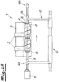
- Fig. 1
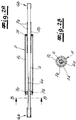
- die Frontansicht einer erfindungsgemäßen Wickelvorrichtung zu Beginn eines Wickelvorgangs,
- Fig. 2A
- einen Horizontalschnitt durch den Wickeldorn aus
Fig. 1 entlang einer Linie A-A, - Fig. 2B
- einen Längsschnitt durch den Wickeldorn aus
Fig. 1 entlang einer Linie B-B, - Fig. 3A
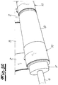
- eine Detailansicht aus
Fig. 1 , - Fig. 3B
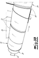
- eine
Fig. 3A entsprechende Ansicht in einer weiteren Phase des Aufwickel prozesses, - Fig. 3C
- eine den Ansichten aus 3A und 3B entsprechende Ansicht zu einem späteren Zeitpunkt während des Aufwickelprozesses,
- Fig.4A
- eine Ansicht entsprechend
Fig. 1 zu einem noch späteren Zeitpunkt des Aufwickelprozesses und - Fig. 4B
- eine Ansicht entsprechend
Fig. 1 und4A zu einem noch späteren Zeitpunkt. - Die
Fig. 1 zeigt eine erfindungsgemäße Vorrichtung 1. Diese ist zum Aufwickeln zumindest eines Materialstreifens 2 vorgesehen. Im Ausführungsbeispiel werden zwei Materialstreifen 2 parallel über eine Kontaktwalze 3 zugeführt. Die beiden Materialstreifen 2 weisen eine identische Breite b auf und werden mit einem Abstand d von zumindest der doppelten Breite b vorzugsweise zumindest der 2,2-fachen Breite zugeführt. Hierdurch wird ein Überlapp der unterschiedlichen Materialstreifen während des Aufwickelns vermieden. - Die Vorrichtung 1 weist einen Wickeldorn 4 auf, welche um eine in einer Axialrichtung x verlaufende Drehachse drehbar angetrieben ist. Der Antrieb 5 zur Erzeugung der Drehbewegung des Wickeldorns 4 ist lediglich schematisch angedeutet. Der Wickeldorn und der Antrieb sind längs der Axialrichtung x ortsfest angeordnet. Der Wickeldorn ist durchgängig ausgebildet und überspannt in der Axialrichtung x zumindest einen Bereich zwischen einer ersten Lagerstelle 6a und einer zweiten Lagerstelle 6b. Im Ausführungsbeispiel sind die Lagerstellen 6a und 6b beidseits der Zuführungswalze 3 angeordnet.
- Erfindungsgemäß ist auf den Wickeldorn 4 eine Wickelwelle 7 angeordnet, welche mit dem Wickeldorn drehfest gekoppelt und in der Axialrichtung x verschiebbar ist. Auf der Wickelwelle 7 sind zwei Wickelkörper 8 jeweils zur Aufnahme der Wicklungen eines Materialstreifens 2 angeordnet. Die Wickelkörper 8 werden durch Papprollen gebildet, welche innenseitig mit der Wickelwelle 7 radial verspannt sind. Die
Fig. 1 stellt die Phase zu Beginn des Wickelprozesses dar, in dem noch keine vollständigen Wickellagen auf die Wickelkörper 8 aufgebracht sind. Lediglich das Ende der Materialstreifen 2 ist bereits an den Wickelkörpern 8 befestigt. - Zur Steuerung der axialen Verschiebung ist ein elektrischer Antrieb 9 vorgesehen, welcher mittels eines Mitnehmers 10 auf eine Nut 7a an einem Fortsatz 7b der Wickelwelle 7 wirkt. Der Mitnehmer 10 ist gleichzeitig auch als Stütze ausgebildet, welcher den Wickeldorn 4 neben den beiden Lagerelementen 6a und 6b trägt.
- In den
Fig. 2A und 2B ist das Zusammenspiel zwischen dem Wickeldorn 4 und der Wickelwelle 7 dargestellt. Der Wickeldorn 4 ist als Vollwelle ausgebildet, welche an ihren Enden Verdickungen für die Lageranordnungen 6a, 6b aufweist. In etwa mittig auf dem Wickeldorn 4 ist die mehrteilig aufgebaute Wickelwelle 7 angeordnet. Die Wickelwelle 7 umfasst einen äußeren Abschnitt 7c, an welchem mit nicht dargestellten Befestigungsmitteln die Wickelkörper 8 befestigbar sind. In der Darstellung gemäßFig. 2A ist am linken Ende des äußeren Abschnitts 7c ein flanschartiges Ende 7d erkennbar. An dem flanschartigen Ende 7d ist ein Vorsprung 7e angeordnet, welcher in eine zugeordnete Nut 4a des Wickeldorns 4 eingreift. Im gezeigten Ausführungsbeispiel ist eine einzige Nut-Feder-Verbindung bestehend aus der Nut 4a und dem Vorsprung 7e vorgesehen. - Das in
Fig. 2A rechtsseitig dargestellte Ende zeigt die rohrförmig ausgebildete Verlängerung 7b der Wickelwelle 7, welche den Wickeldorn 4 konzentrisch und mit einem geringen Abstand umgibt. An der Verlängerung 7b sind zwei in Umfangsrichtung verlaufende Umfangsnuten 7a zu Wechselwirkung mit dem Mitnehmer 10 vorgesehen. Die Kontaktfläche zwischen dem Fortsatz 7b und dem Wickeldorn 4 ist als einfaches Gleitlager ausgebildet, welches sowohl eine translatorische Bewegung in Axialrichtung als auch eine relative Drehbewegung um die Drehachse zulässt. - Die Verbindung zwischen dem äußeren Abschnitt 7c und dem Vorsprung 7a der Verlängerung 7b ist mittels eines Wälzlagers 7f ausgebildet. Das Wälzlager 7f lässt eine relative Drehbewegung um die Drehachse zu, während die Verlängerung 7b und der äußere Abschnitt 7c in axialer Richtung miteinander fest gekoppelt sind. Dies ermöglicht eine geringere oder verschwindende relative Drehbewegung zwischen der Verlängerung 7b und dem Mitnehmer 10 und reduziert somit den Verschleiß.
- Nachfolgend wird das erfindungsgemäße Verfahren zum Aufwickeln eines Materialstreifens erläutert. Zu Beginn des Wickelprozesses, welcher in
Fig. 1 dargestellt ist, sind die beiden Wickelkörper 8 noch leer und lediglich die Enden der Materialstreifen 2 mit den Wickelkörpern 8 verbunden. Die Wickelwelle 7 befindet sich in einer ersten Position bezogen auf die Axialrichtung x, von der sie so weit nach rechts verschoben ist, dass die Materialstreifen 2 nahe des linken Endes der Wickelkörper 8 an diese herangeführt werden. - Durch den Antrieb 5 wird der Wickeldorn 4 in eine Drehbewegung versetzt, welche über die Wickelwelle 7 auf die Wickelkörper 8 übertragen wird. Infolge dessen werden die Materialstreifen 2 auf den Wickelkörpern 8 aufgespult. Es bildet sich dabei ohne axiale Bewegung der Wickelwelle 7 zunächst eine Spule 11 bestehend aus mehreren Lagen des Materialstreifens 2 an der ersten Position. Dies ist in
Fig. 3A dargestellt. Außerhalb der ersten Position liegt noch kein Teil der Materialstreifen 2 auf den Wickelkörpern 8 auf. - Bei Erreichen einer ersten Anzahl von Wicklungen an der ersten Position wird die Wickelwelle bei laufender Drehbewegung axial verschoben. Wie man
Fig. 3B entnimmt, ist die axiale Verfahrgeschwindigkeit dabei so gewählt, dass innerhalb einer Umdrehung der Verfahrweg in Axialrichtung x größer ist als die Breite b des Materialstreifens 2. Infolge dessen wird der Materialstreifen 2 schraubenförmig und ohne Überlapp auf dem Wickelkörper 8 aufgewickelt. - In
Fig. 3B erreicht der Materialstreifen in Bezug auf die Axialrichtung x eine zweite Position im Verhältnis zur Wickelwelle 7. In dieser wird der Materialstreifen nunmehr in der zweiten Position nahe des rechten Endes des Wickelkörpers 8 aufgespult. Der axiale Abstand zwischen der ersten Position und der zweiten Position beträgt zumindest das 2-Fache der Streifenbreite b. Nach Erreichen der zweiten Position (Fig. 3B ) werden dort nunmehr eine zweite Anzahl von Lagen zu einer zweiten Spule aufgewickelt. Nach Erreichen der zweiten Anzahl von Lagen verfährt die Wickelwelle in umgekehrter Richtung jedoch um denselben Betrag a, so dass die Materialstreifen 2 nunmehr wieder an der ersten Position aufgewickelt werden. Dies ist in derFig. 4A in der Gesamtheit der Vorrichtung 1 dargestellt. Die beiden Materialstreifen werden jeweils gleichlaufend auf separaten Wickelkörpern 8 aufgespult. Der Wechsel zwischen der ersten Position und der zweiten Position können, wie man derFig. 4B entnimmt, mehrfach hintereinander wiederholt werden. Somit ergibt sich eine wesentlich stabilere Wicklung auf den Wickelkörpern als wenn dasselbe Material statisch an nur einer Position aufgewickelt würde.
Claims (15)
- Vorrichtung (1) zum Aufwickeln eines Materialstreifens (2) mit einer um eine in einer Axialrichtung (x) verlaufende Drehachse drehbar angetriebenem Wickeldorn (4), dadurch gekennzeichnet, dass auf dem Wickeldorn(4) eine Wickelwelle (7) angeordnet ist, welche mit dem Wickeldorn (4) drehfest gekoppelt und in der Axialrichtung (x) verschiebbar ist.
- Vorrichtung (1) nach Anspruch 1, dadurch gekennzeichnet, dass die drehfeste Kopplung zwischen dem Wickeldorn(4) und der Wickelwelle (7) über zumindest eine in Axialrichtung (x) verlaufende Nut-Feder-Verbindung (4a, 7e) erfolgt, welche eine Verschiebung in der Axialrichtung (x) zulässt.
- Vorrichtung (1) nach Anspruch 1 oder 2, dadurch gekennzeichnet, dass die Verschiebung in der Axialrichtung (x) durch einen hydraulischen Antrieb (9) erfolgt.
- Vorrichtung (1) nach einem der Ansprüche 1 bis 3, dadurch gekennzeichnet, dass die Wickelwelle (7) eine Umfangsnut (7a) aufweist, in welcher ein Mitnehmer (10) zur Verschiebung in der Axialrichtung (x) eingreift.
- Vorrichtung (1) nach einem der Ansprüche 1 bis 4, dadurch gekennzeichnet, dass die Wickelwelle (7) über ein Wellenende abnehmbar ist.
- Vorrichtung (1) nach einem der Ansprüche 1 bis 5, dadurch gekennzeichnet, dass die Wickelwelle (7) Befestigungseinrichtungen für einen Wickelkörper (8), insbesondere eine rohrförmige Rolle, aufweist.
- Verfahren zum Aufwickeln eines Materialstreifens (2) durch eine Vorrichtung (1) nach einem der vorstehenden Ansprüche, wobei der Materialstreifen (2) zugeführt wird, wobei dessen Ende mit der Wickelwelle (7) gekoppelt ist, wobei der Wickeldorn(4) und mit ihr die Wickelwelle (7) durch einen Antrieb (5) in eine Drehbewegung versetzt werden, um den Materialstreifen (2) auf die Wickelwelle (7) aufzuwickeln, und wobei die Wickelwelle während des Drehbetriebs in der Längsrichtung verschoben wird.
- Verfahren nach Anspruch 7, dadurch gekennzeichnet, dass die Verschiebung intermittierend erfolgt.
- Verfahren nach Anspruch 8, dadurch gekennzeichnet, dass zunächst eine Anzahl von Lagen des Materialstreifens (2) an einer ersten Position bezogen auf die Axialrichtung (x) aufgewickelt wird und dass anschließend eine Verschiebung um eine erste Distanz, die bevorzugt zumindest den Betrag der Streifenbreite (b) beträgt, erfolgt und dass anschließend in einer zweiten Position bezogen auf die Axialrichtung (x) mehrere Lagen des Materialstreifens aufgewickelt werden.
- Verfahren nach Anspruch 9, dadurch gekennzeichnet, dass danach eine zweite Anzahl von Lagen des Materialstreifens (12) an der zweiten Position bezogen auf die Axialrichtung (x) aufgewickelt wird und dass anschließend eine Verschiebung um eine zweite Distanz, deren Betrag bevorzugt zumindest der Streifenbreite (b) entspricht, erfolgt und dass anschließend in einer dritten Position bezogen auf die Axialrichtung (x) mehrere Lagen des Materialstreifens (2) aufgewickelt werden.
- Verfahren nach Anspruch 10, dadurch gekennzeichnet, dass die zweite Distanz denselben Betrag jedoch die entgegengesetzte Richtung der ersten Distanz hat, so dass die dritte Position mit der ersten Position identisch ist.
- Verfahren nach Anspruch 10 oder 11, dadurch gekennzeichnet, dass die erste Position und die zweite Position jeweils mehrfach nacheinander angefahren werden.
- Verfahren nach einem der Ansprüche 7 bis 12, dadurch gekennzeichnet, dass die Drehgeschwindigkeit des Wickeldorns(4) so variiert wird, dass die Radialgeschwindigkeit des aufgewickelten Materialstreifens (2) konstant ist.
- Verfahren nach einem der Ansprüche 7 bis 13, dadurch gekennzeichnet, dass eine Vielzahl von Materialstreifen (2) parallel aufgewickelt wird, wobei die Verschiebung in Axialrichtung (x) so gesteuert wird, dass sich die Wicklungen unterschiedlicher Materialstreifen nicht berühren.
- Verfahren nach Anspruch 14, dadurch gekennzeichnet, dass die verschiedenen Materialstreifen (2) Teilstreifen einer gemeinsamen Materialbahn sind, welche durch Trennung in Längsrichtung hergestellt werden.
Priority Applications (5)
| Application Number | Priority Date | Filing Date | Title |
|---|---|---|---|
| ES17195223T ES2969017T3 (es) | 2017-10-06 | 2017-10-06 | Procedimiento para el enrollado de una tira de material |
| EP17195223.7A EP3466642B1 (de) | 2017-10-06 | 2017-10-06 | Verfahren zum aufwickeln eines materialstreifens |
| PCT/EP2018/073894 WO2019068410A1 (de) | 2017-10-06 | 2018-09-05 | Transportgebinde mit einem kunststofflaminat sowie verfahren zur handhabung eines kunststofflaminats |
| PCT/EP2018/073896 WO2019068411A1 (de) | 2017-10-06 | 2018-09-05 | Vorrichtung und verfahren zum aufwickeln eines materialstreifens |
| DE112018004475.0T DE112018004475A5 (de) | 2017-10-06 | 2018-09-05 | Transportgebinde mit einem Kunststofflaminat sowie Verfahren zur Handhabung eines Kunststofflaminats |
Applications Claiming Priority (1)
| Application Number | Priority Date | Filing Date | Title |
|---|---|---|---|
| EP17195223.7A EP3466642B1 (de) | 2017-10-06 | 2017-10-06 | Verfahren zum aufwickeln eines materialstreifens |
Publications (3)
| Publication Number | Publication Date |
|---|---|
| EP3466642A1 true EP3466642A1 (de) | 2019-04-10 |
| EP3466642B1 EP3466642B1 (de) | 2023-12-06 |
| EP3466642C0 EP3466642C0 (de) | 2023-12-06 |
Family
ID=60043040
Family Applications (1)
| Application Number | Title | Priority Date | Filing Date |
|---|---|---|---|
| EP17195223.7A Active EP3466642B1 (de) | 2017-10-06 | 2017-10-06 | Verfahren zum aufwickeln eines materialstreifens |
Country Status (4)
| Country | Link |
|---|---|
| EP (1) | EP3466642B1 (de) |
| DE (1) | DE112018004475A5 (de) |
| ES (1) | ES2969017T3 (de) |
| WO (2) | WO2019068410A1 (de) |
Citations (8)
| Publication number | Priority date | Publication date | Assignee | Title |
|---|---|---|---|---|
| DE1186722B (de) | 1963-10-02 | 1965-02-04 | Windmoeller & Hoelscher | Aufwickelvorrichtung fuer Werkstoffbahnen mit in Laengsrichtung verlaufenden Verdickungen |
| EP0428808A1 (de) * | 1989-11-22 | 1991-05-29 | Compagnie Francaise Pour Le Developpement De La Geothermie Et Des Energies Nouvelles Societe Anonyme : | Verfahren zur Herstellung eines Rohres aus Verbundmaterial des Faser/Harz-Typs und verfahrensgemäss hergestelltes Rohr |
| DE4414003A1 (de) | 1994-04-22 | 1995-10-26 | Kampf Gmbh & Co Maschf | Verfahren und Vorrichtung zum Aufwickeln von Warenbahnen, insbesondere Kunststoffolien in einer Mehrfach-Wendewickelmaschine |
| US5766348A (en) * | 1993-08-31 | 1998-06-16 | Leybold Aktiengesellschaft | Rotating head for crystal pulling systems for carrying out the czochralski process |
| JP2001002379A (ja) * | 1999-06-28 | 2001-01-09 | Tadano Eng:Kk | ホイスト |
| EP2295703A1 (de) * | 2009-08-21 | 2011-03-16 | Jørn Krab Holding APS | Hebemechanismus für Jalousie |
| DE112010004858T5 (de) | 2009-12-18 | 2013-01-17 | Metso Paper, Inc. | Aufwickelvorrichtung zum kontinuierlichen Aufwickeln einer Faserbahn |
| JP2013075750A (ja) * | 2011-09-30 | 2013-04-25 | Furukawa Electric Co Ltd:The | 線条体巻付けボビン、線条体巻取り方法、及び、線条体巻取り装置 |
Family Cites Families (4)
| Publication number | Priority date | Publication date | Assignee | Title |
|---|---|---|---|---|
| JP3959247B2 (ja) * | 2001-02-16 | 2007-08-15 | ソニーケミカル&インフォメーションデバイス株式会社 | リール部材及びフィルムの巻取方法 |
| US9376782B1 (en) * | 2008-09-19 | 2016-06-28 | Mohammad R. Ehsani | Repair and strengthening of piles and pipes with FRP laminates |
| DE102014226859B4 (de) * | 2014-12-22 | 2020-06-18 | Windmöller & Hölscher Kg | Rollenentnahmeeinrichtung, Wickeleinrichtung und Verfahren zum Abtransport von mehreren fertig gewickelten Rollen |
| KR101862536B1 (ko) * | 2014-12-25 | 2018-05-29 | 스미또모 가가꾸 가부시키가이샤 | 세퍼레이터 권회체의 제조 방법 및 세퍼레이터의 슬릿 방법 |
-
2017
- 2017-10-06 EP EP17195223.7A patent/EP3466642B1/de active Active
- 2017-10-06 ES ES17195223T patent/ES2969017T3/es active Active
-
2018
- 2018-09-05 WO PCT/EP2018/073894 patent/WO2019068410A1/de not_active Ceased
- 2018-09-05 DE DE112018004475.0T patent/DE112018004475A5/de not_active Withdrawn
- 2018-09-05 WO PCT/EP2018/073896 patent/WO2019068411A1/de not_active Ceased
Patent Citations (8)
| Publication number | Priority date | Publication date | Assignee | Title |
|---|---|---|---|---|
| DE1186722B (de) | 1963-10-02 | 1965-02-04 | Windmoeller & Hoelscher | Aufwickelvorrichtung fuer Werkstoffbahnen mit in Laengsrichtung verlaufenden Verdickungen |
| EP0428808A1 (de) * | 1989-11-22 | 1991-05-29 | Compagnie Francaise Pour Le Developpement De La Geothermie Et Des Energies Nouvelles Societe Anonyme : | Verfahren zur Herstellung eines Rohres aus Verbundmaterial des Faser/Harz-Typs und verfahrensgemäss hergestelltes Rohr |
| US5766348A (en) * | 1993-08-31 | 1998-06-16 | Leybold Aktiengesellschaft | Rotating head for crystal pulling systems for carrying out the czochralski process |
| DE4414003A1 (de) | 1994-04-22 | 1995-10-26 | Kampf Gmbh & Co Maschf | Verfahren und Vorrichtung zum Aufwickeln von Warenbahnen, insbesondere Kunststoffolien in einer Mehrfach-Wendewickelmaschine |
| JP2001002379A (ja) * | 1999-06-28 | 2001-01-09 | Tadano Eng:Kk | ホイスト |
| EP2295703A1 (de) * | 2009-08-21 | 2011-03-16 | Jørn Krab Holding APS | Hebemechanismus für Jalousie |
| DE112010004858T5 (de) | 2009-12-18 | 2013-01-17 | Metso Paper, Inc. | Aufwickelvorrichtung zum kontinuierlichen Aufwickeln einer Faserbahn |
| JP2013075750A (ja) * | 2011-09-30 | 2013-04-25 | Furukawa Electric Co Ltd:The | 線条体巻付けボビン、線条体巻取り方法、及び、線条体巻取り装置 |
Also Published As
| Publication number | Publication date |
|---|---|
| DE112018004475A5 (de) | 2020-06-04 |
| EP3466642B1 (de) | 2023-12-06 |
| EP3466642C0 (de) | 2023-12-06 |
| WO2019068411A1 (de) | 2019-04-11 |
| WO2019068410A1 (de) | 2019-04-11 |
| ES2969017T3 (es) | 2024-05-16 |
Similar Documents
| Publication | Publication Date | Title |
|---|---|---|
| DE69404473T2 (de) | Maschine zum herstellen von rohren aus pappe oder ähnlichem material, mit einer vorrichtung zum in stücke schneiden von rohren mit vorbestimmten längen | |
| DE2304648C3 (de) | Maschine zur Herstellung von Bewehrungskörpern in Form eines auf Teilen seiner Länge aufweitbaren Umdrehungskörpers | |
| DE102014001414B4 (de) | Ablegekopf zum automatisierten Ablegen eines flächigen Materials, sowie Verwendung eines derartigen Ablegekopfes | |
| DE60101373T2 (de) | Vorrichtung zum auf- und abwickeln von dünnen bändern mit automatischer zentrierung | |
| DE102013002022B4 (de) | Vorrichtung zum Wickeln eines strangförmigen Wickelguts und Verfahren dazu | |
| EP4124441B1 (de) | Folienaufwickelsystem, verbund aus einer folienreckanlage und einem solchen folienaufwickelsystem und verwendung eines solchen verbunds zur herstellung von dünnstfilmen und membranen | |
| DE1928201B2 (de) | Wickeldorn zum kontinuierlichen Herstellen von rohrförmigen Gegenständen | |
| EP1043119A2 (de) | Verfahren und Vorrichtung zum Aussenrundschleifen dünnwandiger Rohre | |
| EP2960194A1 (de) | Falzwalze mit gummielastischen einlagen | |
| EP2823943B1 (de) | Vorrichtung und Verfahren zum Längsteilen einer durchlaufenden Materialbahn | |
| EP1190971A2 (de) | Einrichtung zum Verstellen von Fördereinrichtungen für flächige Exemplare in Rotationsdruckmaschinen | |
| EP1947043B1 (de) | Wickeleinrichtung | |
| DE102011001835A1 (de) | Verfahren und Vorrichtung zur Verarbeitung eines Bandes | |
| EP0024029B1 (de) | Beschichtungsvorrichtung für bandförmiges Gut, insbesondere Metallbänder | |
| EP3466642B1 (de) | Verfahren zum aufwickeln eines materialstreifens | |
| EP1386035B1 (de) | Vorrichtung zum einziehen einer materialbahn | |
| WO1998023517A1 (de) | Vorrichtung zum aufteilen eines stromes von signaturen | |
| DE19857205B4 (de) | Verfahren zum Aufwickeln einer kontinuierlich zugeführten Materialbahn | |
| WO2012084638A1 (de) | Vorrichtung und verfahren zum walzen eines metallbandes | |
| DE102011087482A1 (de) | Vorrichtung zum Längsschneiden von laufenden Materialbahnen, insbesondere Kunststofffolien | |
| EP2877319B1 (de) | Verfahren zum strukturieren eines pressbandes | |
| EP3774616B1 (de) | Wickeleinrichtung mit mehreren wickelwellen | |
| WO1998047803A2 (de) | Einrichtung zum querfalzen von signaturen | |
| DE3637634C2 (de) | ||
| DE102007014079A1 (de) | Verfahren und Vorrichtung zum Walzen von Walzgut in einer Walzanlage mit einem Schrägwalzwerk |
Legal Events
| Date | Code | Title | Description |
|---|---|---|---|
| PUAI | Public reference made under article 153(3) epc to a published international application that has entered the european phase |
Free format text: ORIGINAL CODE: 0009012 |
|
| STAA | Information on the status of an ep patent application or granted ep patent |
Free format text: STATUS: THE APPLICATION HAS BEEN PUBLISHED |
|
| AK | Designated contracting states |
Kind code of ref document: A1 Designated state(s): AL AT BE BG CH CY CZ DE DK EE ES FI FR GB GR HR HU IE IS IT LI LT LU LV MC MK MT NL NO PL PT RO RS SE SI SK SM TR |
|
| AX | Request for extension of the european patent |
Extension state: BA ME |
|
| STAA | Information on the status of an ep patent application or granted ep patent |
Free format text: STATUS: REQUEST FOR EXAMINATION WAS MADE |
|
| 17P | Request for examination filed |
Effective date: 20190522 |
|
| RBV | Designated contracting states (corrected) |
Designated state(s): AL AT BE BG CH CY CZ DE DK EE ES FI FR GB GR HR HU IE IS IT LI LT LU LV MC MK MT NL NO PL PT RO RS SE SI SK SM TR |
|
| STAA | Information on the status of an ep patent application or granted ep patent |
Free format text: STATUS: EXAMINATION IS IN PROGRESS |
|
| 17Q | First examination report despatched |
Effective date: 20211221 |
|
| RAP1 | Party data changed (applicant data changed or rights of an application transferred) |
Owner name: NITTO ADVANCED FILM GRONAU GMBH |
|
| P01 | Opt-out of the competence of the unified patent court (upc) registered |
Effective date: 20230504 |
|
| GRAP | Despatch of communication of intention to grant a patent |
Free format text: ORIGINAL CODE: EPIDOSNIGR1 |
|
| STAA | Information on the status of an ep patent application or granted ep patent |
Free format text: STATUS: GRANT OF PATENT IS INTENDED |
|
| INTG | Intention to grant announced |
Effective date: 20230705 |
|
| GRAS | Grant fee paid |
Free format text: ORIGINAL CODE: EPIDOSNIGR3 |
|
| GRAA | (expected) grant |
Free format text: ORIGINAL CODE: 0009210 |
|
| STAA | Information on the status of an ep patent application or granted ep patent |
Free format text: STATUS: THE PATENT HAS BEEN GRANTED |
|
| AK | Designated contracting states |
Kind code of ref document: B1 Designated state(s): AL AT BE BG CH CY CZ DE DK EE ES FI FR GB GR HR HU IE IS IT LI LT LU LV MC MK MT NL NO PL PT RO RS SE SI SK SM TR |
|
| REG | Reference to a national code |
Ref country code: GB Ref legal event code: FG4D Free format text: NOT ENGLISH |
|
| REG | Reference to a national code |
Ref country code: CH Ref legal event code: EP |
|
| REG | Reference to a national code |
Ref country code: DE Ref legal event code: R096 Ref document number: 502017015652 Country of ref document: DE |
|
| REG | Reference to a national code |
Ref country code: IE Ref legal event code: FG4D Free format text: LANGUAGE OF EP DOCUMENT: GERMAN |
|
| U01 | Request for unitary effect filed |
Effective date: 20231220 |
|
| U07 | Unitary effect registered |
Designated state(s): AT BE BG DE DK EE FI FR IT LT LU LV MT NL PT SE SI Effective date: 20240103 |
|
| P04 | Withdrawal of opt-out of the competence of the unified patent court (upc) registered |
Effective date: 20231222 |
|
| PG25 | Lapsed in a contracting state [announced via postgrant information from national office to epo] |
Ref country code: GR Free format text: LAPSE BECAUSE OF FAILURE TO SUBMIT A TRANSLATION OF THE DESCRIPTION OR TO PAY THE FEE WITHIN THE PRESCRIBED TIME-LIMIT Effective date: 20240307 |
|
| PG25 | Lapsed in a contracting state [announced via postgrant information from national office to epo] |
Ref country code: GR Free format text: LAPSE BECAUSE OF FAILURE TO SUBMIT A TRANSLATION OF THE DESCRIPTION OR TO PAY THE FEE WITHIN THE PRESCRIBED TIME-LIMIT Effective date: 20240307 |
|
| REG | Reference to a national code |
Ref country code: ES Ref legal event code: FG2A Ref document number: 2969017 Country of ref document: ES Kind code of ref document: T3 Effective date: 20240516 |
|
| PG25 | Lapsed in a contracting state [announced via postgrant information from national office to epo] |
Ref country code: RS Free format text: LAPSE BECAUSE OF FAILURE TO SUBMIT A TRANSLATION OF THE DESCRIPTION OR TO PAY THE FEE WITHIN THE PRESCRIBED TIME-LIMIT Effective date: 20231206 Ref country code: NO Free format text: LAPSE BECAUSE OF FAILURE TO SUBMIT A TRANSLATION OF THE DESCRIPTION OR TO PAY THE FEE WITHIN THE PRESCRIBED TIME-LIMIT Effective date: 20240306 Ref country code: HR Free format text: LAPSE BECAUSE OF FAILURE TO SUBMIT A TRANSLATION OF THE DESCRIPTION OR TO PAY THE FEE WITHIN THE PRESCRIBED TIME-LIMIT Effective date: 20231206 |
|
| PG25 | Lapsed in a contracting state [announced via postgrant information from national office to epo] |
Ref country code: IS Free format text: LAPSE BECAUSE OF FAILURE TO SUBMIT A TRANSLATION OF THE DESCRIPTION OR TO PAY THE FEE WITHIN THE PRESCRIBED TIME-LIMIT Effective date: 20240406 |
|
| PG25 | Lapsed in a contracting state [announced via postgrant information from national office to epo] |
Ref country code: CZ Free format text: LAPSE BECAUSE OF FAILURE TO SUBMIT A TRANSLATION OF THE DESCRIPTION OR TO PAY THE FEE WITHIN THE PRESCRIBED TIME-LIMIT Effective date: 20231206 |
|
| PG25 | Lapsed in a contracting state [announced via postgrant information from national office to epo] |
Ref country code: SK Free format text: LAPSE BECAUSE OF FAILURE TO SUBMIT A TRANSLATION OF THE DESCRIPTION OR TO PAY THE FEE WITHIN THE PRESCRIBED TIME-LIMIT Effective date: 20231206 |
|
| PG25 | Lapsed in a contracting state [announced via postgrant information from national office to epo] |
Ref country code: SM Free format text: LAPSE BECAUSE OF FAILURE TO SUBMIT A TRANSLATION OF THE DESCRIPTION OR TO PAY THE FEE WITHIN THE PRESCRIBED TIME-LIMIT Effective date: 20231206 Ref country code: SK Free format text: LAPSE BECAUSE OF FAILURE TO SUBMIT A TRANSLATION OF THE DESCRIPTION OR TO PAY THE FEE WITHIN THE PRESCRIBED TIME-LIMIT Effective date: 20231206 Ref country code: RO Free format text: LAPSE BECAUSE OF FAILURE TO SUBMIT A TRANSLATION OF THE DESCRIPTION OR TO PAY THE FEE WITHIN THE PRESCRIBED TIME-LIMIT Effective date: 20231206 Ref country code: IS Free format text: LAPSE BECAUSE OF FAILURE TO SUBMIT A TRANSLATION OF THE DESCRIPTION OR TO PAY THE FEE WITHIN THE PRESCRIBED TIME-LIMIT Effective date: 20240406 Ref country code: CZ Free format text: LAPSE BECAUSE OF FAILURE TO SUBMIT A TRANSLATION OF THE DESCRIPTION OR TO PAY THE FEE WITHIN THE PRESCRIBED TIME-LIMIT Effective date: 20231206 |
|
| PG25 | Lapsed in a contracting state [announced via postgrant information from national office to epo] |
Ref country code: PL Free format text: LAPSE BECAUSE OF FAILURE TO SUBMIT A TRANSLATION OF THE DESCRIPTION OR TO PAY THE FEE WITHIN THE PRESCRIBED TIME-LIMIT Effective date: 20231206 |
|
| PG25 | Lapsed in a contracting state [announced via postgrant information from national office to epo] |
Ref country code: PL Free format text: LAPSE BECAUSE OF FAILURE TO SUBMIT A TRANSLATION OF THE DESCRIPTION OR TO PAY THE FEE WITHIN THE PRESCRIBED TIME-LIMIT Effective date: 20231206 |
|
| REG | Reference to a national code |
Ref country code: DE Ref legal event code: R097 Ref document number: 502017015652 Country of ref document: DE |
|
| PLBE | No opposition filed within time limit |
Free format text: ORIGINAL CODE: 0009261 |
|
| STAA | Information on the status of an ep patent application or granted ep patent |
Free format text: STATUS: NO OPPOSITION FILED WITHIN TIME LIMIT |
|
| U20 | Renewal fee for the european patent with unitary effect paid |
Year of fee payment: 8 Effective date: 20240912 |
|
| 26N | No opposition filed |
Effective date: 20240909 |
|
| P05 | Withdrawal of opt-out of the competence of the unified patent court (upc) changed |
Free format text: CASE NUMBER: APP_597261/2023 Effective date: 20240103 |
|
| REG | Reference to a national code |
Ref country code: CH Ref legal event code: PL |
|
| GBPC | Gb: european patent ceased through non-payment of renewal fee |
Effective date: 20241006 |
|
| PG25 | Lapsed in a contracting state [announced via postgrant information from national office to epo] |
Ref country code: MC Free format text: LAPSE BECAUSE OF FAILURE TO SUBMIT A TRANSLATION OF THE DESCRIPTION OR TO PAY THE FEE WITHIN THE PRESCRIBED TIME-LIMIT Effective date: 20231206 |
|
| PG25 | Lapsed in a contracting state [announced via postgrant information from national office to epo] |
Ref country code: GB Free format text: LAPSE BECAUSE OF NON-PAYMENT OF DUE FEES Effective date: 20241006 |
|
| PG25 | Lapsed in a contracting state [announced via postgrant information from national office to epo] |
Ref country code: CH Free format text: LAPSE BECAUSE OF NON-PAYMENT OF DUE FEES Effective date: 20241031 |
|
| PGFP | Annual fee paid to national office [announced via postgrant information from national office to epo] |
Ref country code: TR Payment date: 20250929 Year of fee payment: 9 |
|
| PG25 | Lapsed in a contracting state [announced via postgrant information from national office to epo] |
Ref country code: IE Free format text: LAPSE BECAUSE OF NON-PAYMENT OF DUE FEES Effective date: 20241006 |
|
| U20 | Renewal fee for the european patent with unitary effect paid |
Year of fee payment: 9 Effective date: 20251014 |
|
| PG25 | Lapsed in a contracting state [announced via postgrant information from national office to epo] |
Ref country code: CY Free format text: LAPSE BECAUSE OF FAILURE TO SUBMIT A TRANSLATION OF THE DESCRIPTION OR TO PAY THE FEE WITHIN THE PRESCRIBED TIME-LIMIT; INVALID AB INITIO Effective date: 20171006 |
|
| PGFP | Annual fee paid to national office [announced via postgrant information from national office to epo] |
Ref country code: ES Payment date: 20251216 Year of fee payment: 9 |
|
| PG25 | Lapsed in a contracting state [announced via postgrant information from national office to epo] |
Ref country code: HU Free format text: LAPSE BECAUSE OF FAILURE TO SUBMIT A TRANSLATION OF THE DESCRIPTION OR TO PAY THE FEE WITHIN THE PRESCRIBED TIME-LIMIT; INVALID AB INITIO Effective date: 20171006 |