EP3466552B1 - Aufbau eines sortierzentrums, das ein in schleife laufendes förderband umfasst - Google Patents
Aufbau eines sortierzentrums, das ein in schleife laufendes förderband umfasst Download PDFInfo
- Publication number
- EP3466552B1 EP3466552B1 EP18188485.9A EP18188485A EP3466552B1 EP 3466552 B1 EP3466552 B1 EP 3466552B1 EP 18188485 A EP18188485 A EP 18188485A EP 3466552 B1 EP3466552 B1 EP 3466552B1
- Authority
- EP
- European Patent Office
- Prior art keywords
- conveyor
- zones
- articles
- injection
- sorting
- Prior art date
- Legal status (The legal status is an assumption and is not a legal conclusion. Google has not performed a legal analysis and makes no representation as to the accuracy of the status listed.)
- Active
Links
Images


Classifications
-
- B—PERFORMING OPERATIONS; TRANSPORTING
- B65—CONVEYING; PACKING; STORING; HANDLING THIN OR FILAMENTARY MATERIAL
- B65G—TRANSPORT OR STORAGE DEVICES, e.g. CONVEYORS FOR LOADING OR TIPPING, SHOP CONVEYOR SYSTEMS OR PNEUMATIC TUBE CONVEYORS
- B65G47/00—Article or material-handling devices associated with conveyors; Methods employing such devices
- B65G47/52—Devices for transferring articles or materials between conveyors i.e. discharging or feeding devices
- B65G47/68—Devices for transferring articles or materials between conveyors i.e. discharging or feeding devices adapted to receive articles arriving in one layer from one conveyor lane and to transfer them in individual layers to more than one conveyor lane or to one broader conveyor lane, or vice versa, e.g. combining the flows of articles conveyed by more than one conveyor
- B65G47/71—Devices for transferring articles or materials between conveyors i.e. discharging or feeding devices adapted to receive articles arriving in one layer from one conveyor lane and to transfer them in individual layers to more than one conveyor lane or to one broader conveyor lane, or vice versa, e.g. combining the flows of articles conveyed by more than one conveyor the articles being discharged or distributed to several distinct separate conveyors or to a broader conveyor lane
-
- B—PERFORMING OPERATIONS; TRANSPORTING
- B07—SEPARATING SOLIDS FROM SOLIDS; SORTING
- B07C—POSTAL SORTING; SORTING INDIVIDUAL ARTICLES, OR BULK MATERIAL FIT TO BE SORTED PIECE-MEAL, e.g. BY PICKING
- B07C3/00—Sorting according to destination
- B07C3/02—Apparatus characterised by the means used for distribution
- B07C3/08—Apparatus characterised by the means used for distribution using arrangements of conveyors
Definitions
- the invention is in the field of transport and distribution logistics, and more specifically in the field of infrastructure for sorting articles such as letters or parcels.
- Sorting centers include conveying devices whose increase in flow rates comes up against kinematic limits: the possible accelerations and speeds are limited by the need to keep the articles on said conveying devices.
- a sorting center can be built around a loop conveyor conveying articles in series.
- the European patent EP3147038 and the patent application US 2007/0203612 describe an architecture and a mode of use of a sorting center allowing an efficient use of such a conveyor, the latter being partitioned into injection zones alternating with exit zones.
- the items are sorted upstream of the loop conveyor, or pre-sorted, the injection area of a given item being determined by its destination (delivery address) or any other sorting criteria, such as its shape or weight.
- the conveyor comprises two injection zones and two exit zones, this arrangement makes it possible to inject the articles on locations of the conveyor by a first injection zone upstream from the exit zone through which they must be discharged from the conveyor, and to free up the locations before they pass through the second injection zone.
- each location of the conveyor can be used up to once at each injection area. In case the articles are separated into two pre-sorted flows, each location can be used up to twice per turn.
- the object of the invention is to optimize the efficiency of use of a loop conveyor of a sorting center by means of an architecture for sorting infrastructure of articles combining pre-sorting devices. being able to process in parallel articles received at the sorting center with the injection of the articles according to a topology in which the injection points of the articles pre-sorted by different pre-sorting devices are interleaved, or alternated.
- a sorting infrastructure makes it possible to separate, independently for several reception zones each comprising, for example, one or more unloading docks where articles to be sorted are unloaded from delivery trucks, articles to be sorted arriving at these article reception zones and conveying them to injection zones of a loop conveyor which are alternated with exit zones of the conveyor along the loop formed by the latter.
- control-command unit arranged to calculate, from the advance knowledge of the articles to be sorted and sorting information associated with these articles, for example in the form of data. archived in a database accessible by the control-command unit, an optimized distribution of the pre-sorted articles in the conveyor lines so as to balance the flow rates of articles between the exit zones while imposing a constraint according to which an article injected onto the conveyor from a given pre-sorting device connected to several injection zones by corresponding conveyor lines, which is injected onto the conveyor from a certain injection zone connected to said given pre-sorting device, is discharged from the conveyor before passing through another injection zone which is connected to said given pre-sorting device.
- the object of the invention is to improve the efficiency of a sorting center by increasing the operational flow rate Do of a loop conveyor which depends on i) the mechanical flow rate of the conveyor Dm, fixed by its physical characteristics (dimensions, speed), and ii) the number of uses per revolution of a conveyor location, represented by the multiplier M.
- M is an operational value, depending on the mode of use of the conveyor, and not a value only fixed by the topology of the elements of the sorting center.
- M depends both on the architecture of the center and on the way it is operated. To achieve its goal, the invention goes through an architecture making it possible to obtain multipliers M significantly higher than conventional architectures.
- the injection zones and the exit zones are represented by ZI and ZS, respectively, numbered from 1 to 6, and distributed along the loop formed by the conveyor according to their number in the direction of rotation S.
- a traffic balance at each point P j located between the injection area j and the exit area j with j varying from 1 to n can be established.
- the sorter trays are occupied by the objects injected at each injection injection zone i (from 1 to n) and not yet released when passing through P j .
- o (i, j) be the proportion of trays loaded at the injection area i and still occupied when passing from point P j .
- ⁇ j , o j j 1 since in P j a tray has just passed in front of the injection zone j and that no article injected by this injection zone on this tray has yet been unloaded towards an outlet of the sorter.
- the maximum system flow is reached when the sorter flow is maximum after each injection zone (at each point P j above).
- the multiplier M is entirely determined by the matrix A of the ⁇ (i, j).
- the patent document method EP3147038 to increase the multiplier M is based on an architecture allowing a separation of the articles arriving at a reception zone upstream of a loop conveyor.
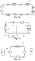
- Incoming items are separated into n pre-sorted flows of identical sizes destined for n corresponding exit zones of a loop conveyor via n corresponding injection zones of the conveyor, each of the injection zones being situated between two adjacent exit zones.
- the articles injected by the same injection zone are entirely evacuated from the conveyor by the same exit zone.
- the pre-sorting is carried out so that each location of the conveyor loaded by an injection line in an injection zone ZI is released at an exit zone before being presented to the injection zone Next ZI. More specifically, the articles are pre-sorted so that an article destined for an exit from the exit zone i will be injected onto the conveyor via the injection zone i, located upstream of and contiguous to the exit zone i, for i equal to 1, 2, or 3.
- each plate of the conveyor can be used up to three times per revolution.
- M is n.
- Another architecture consists in supplying a conveyor by at least two receiving zones in parallel and interleaving, or alternating, the output zones and the corresponding injection zones.
- Such architecture is illustrated by the figure 1C for the case of two ZR reception zones in parallel, ZR-1 and ZR-2, and two ZS output zones, ZS-1 and ZS-2.
- the collected articles are transferred in flow 130 to two injection zones ZI, ZI-1 and ZI-2.
- the object of the invention is to combine the method of separating the flows with the method of interleaving the injection and exit zones of several reception zones, so as to combine the advantages, and the multipliers M, of each methods.
- the inventors have determined an architecture allowing this combination.
- a logistic installation for processing articles to be sorted comprises a loop conveyor for conveying articles to be sorted according to a loop circulation plan, the conveyor comprising as many injection zones as exit zones.
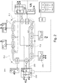
- the figure 2 illustrates a logistics installation 200 according to the invention, comprising, for example, two reception zones ZR, ZR1 and ZR2, for receiving unsorted articles and six dispatch zones ZE, ZE1 to ZE6, for dispatching the sorted articles.
- ZR receiving areas and ZE shipping areas include 230 truck loading docks and 240 truck loading docks, respectively.
- the logistics platform 200 integrates a loop conveyor 210, for example a plate conveyor, comprising six injection zones ZI, ZI-1 to ZI-6, for injecting the articles on the conveyor, the injection zones ZI alternating one by one with six exit zones ZS, ZS-1 to ZS-6, to unload the conveyor.
- a loop conveyor 210 for example a plate conveyor, comprising six injection zones ZI, ZI-1 to ZI-6, for injecting the articles on the conveyor, the injection zones ZI alternating one by one with six exit zones ZS, ZS-1 to ZS-6, to unload the conveyor.
- the arriving articles are separated in this example into three streams 220 of articles pre-sorted by pre-sorting devices PT, PT1 and PT2, at each reception zone ZR, ZR1 and ZR2, that is to say in six streams 220 in total.
- the articles pre-sorted by a given PT pre-sorting device are distributed between three of the injection zones ZI via conveyor lines 330 illustrated in figure 3A .
- Each flow 220 is identified on the figure 2 by a pair of figures p: q, p indicating the pre-sorting device of origin of the stream of pre-sorted articles and q a stream number.
- p is 1 or 2
- q is 1, 2 or 3.
- the injection zones ZI and outlet ZS are distributed along the conveyor in their order of numbering according to the direction S of rotation of the conveyor.
- Each injection zone ZI-i is located upstream of and contiguous to an exit zone ZS-i, i being equal to 1 to 6. In this way, each injection zone is contiguous to and surrounded by two of the zones of ZS outlet and each ZS outlet area is contiguous to and surrounded by two of the ZI injection areas.
- figure 2 illustrates only one particular case, and the number of reception zones ZR and exit ZS is limited only by practical constraints of space and / or economic.
- the PT1 pre-sorting device is connected to the injection zones ZI-1, ZI-3 and ZI-5 , the pre-sorting can be carried out so that the packages injected in ZI-1 are unloaded in ZS-1 or ZS-2, the packages injected in ZI-3 are unloaded in ZS-3 or ZS-4 and the packages injected in ZI-5 are unloaded in ZS-5 or ZS-6, and the PT2 pre-sorting device is connected to the ZI-2, ZI-4 and ZI-6 injection zones, pre-sorting can be carried out so that the packages injected in ZI-2 are unloaded in ZS-2 or ZS-3, packages injected in ZI-4 are unloaded in ZS-4 or ZS-5 and packages injected in ZI-6 are unloaded in ZS-6 or ZS-1.
- each pre-sorting device is connected to a single injection zone every 2 injection zones considered sequentially along the conveyor in
- the loop conveyor is made up of contiguous partitions P two by two, each partition comprising injection zones ZI collectively connected to each of the reception zones by the conveyor lines 330.
- a first partition P-1 comprises, the injection zones ZI-1 and ZI-2
- a second partition P-2 comprises the injection zones ZI-3 and ZI-4
- a third partition P-3 comprises the injection zones ZI-5 and ZI-6.
- each of the partitions P is connected to each of the reception zones ZR1 and ZR2 by the conveyor lines 330.
- the reception areas ZR are equipped with detection and identification devices Id of the articles to detect and identify the articles unloaded from the trucks, and with pre-sorting devices PT to pre-sort the identified articles so as to separate them into three flow 220 according to their identification and a sorting plan prepared in advance.
- Each flow 220 is supported by one or more conveyor lines 330 (depending on the target flow) illustrated by figure 3A .
- Each conveyor line connects one of the PT pre-sorting devices to an injection point in one of the injection zones ZI.
- the detection and identification devices can be optical barcode or square code readers, optical sensors fitted with character recognition systems, or even radio-identification identification chip detectors.
- the figure 3A illustrates a PT pre-sorting device integrated into a ZR reception zone for pre-sorting articles received at the unloading docks 230.
- the articles are placed on conveyors 320 by handling means 310 and then routed on the conveyor lines 330 by routing devices 340.
- the conveyors 320 and the conveyor lines 330 can be, for example, plate conveyors, tape, or roller.
- the handling means can be manual positioning of the articles by operators or automated unloading systems. In this illustration, each of the three flows 1: 1, 1: 2 and 1: 3 is supported by two conveyor lines 330, but this example is not limiting.
- the figure 3B illustrates the exit zones ZI, which include exit points 360 where the articles are discharged from the loop conveyor 340 by exit RT routing devices.
- the routing device is designed to orient the articles towards exits, and may consist, for example, of a device for tilting the trays 340 of the conveyor 210 to drop the articles in receiving bins 350 materializing the exits.
- the bins can be replaced by other types of container or supports such as boxes, pallets, trolleys or shuttles.
- the articles are transported in the bins to the ZE shipping areas where the 240 loading docks are located to be re-shipped by truck.
- a control unit 250 is connected to a database 255 listing g articles A, A1 to Ag, to be sorted in a given period, and associating them with, for example, destinations D, D1 to Dh. G and h represent positive integers.
- the control-command unit 250 is connected to the detection and identification devices Id and controls the pre-sorting devices PT of the reception areas ZR and of the routing devices RT of the exit areas ZS.
- Efficient sorting of articles is based on a good balance of article flow rates between the ZS exit zones. Knowing in advance the articles A to be sorted and their sorting information D, such as destinations, makes it possible to assign the destinations to the sorting output zones and to control the pre-sorting devices of the reception and sorting zones. routing of the exit zones so as to balance the flow rates at the exit zones.
- a protocol for using the logistics platform 200 is as follows, illustrated by the figure 4 .
- a step 410 the data relating to the articles A to be sorted during the period and to their destinations D are received and stored in the database 255.
- control unit 250 accesses the data in the database and draws up a sorting plan for the period according to the volumes of articles to be conveyed to each of the destinations: to each exit zone ZS and exit points 360 are assigned one or more destinations D. This assignment defines the sorting plan.
- the following is a method of assigning item destinations to the output areas based on the number of items to be routed to each destination.
- the destinations are listed in descending order of the number of items to be shipped there.
- 25 D destinations are concerned, they can be classified from 1 to 25, i.e. D01 to D25.
- the destinations are then assigned to the n exit zones of the conveyor by oscillation: the first n destinations are assigned to the n first exit zones, respectively.
- destinations (n + 1) to 2n are assigned to the outputs in the reverse order of the first n departments, and so on.
- destinations 1 to 6 are assigned respectively to exit zones 1 to 6, destinations 7 to 12 to exit zones 6 to 1, destinations 13 to 18 to exit zones 1 to 6, destinations 19 to 24 to exit zones 6 to 1, and destination 25 to exit zone 1.
- the associations formed are then (D01, ZS-1), (D02, ZS-2), (D03, ZS-3), (D04, ZS-4), (D05, ZS-5), (D06, ZS- 6), (D07, ZS-6), (D08, ZS-5), (D09, ZS-4), (D10, ZS-3), (D11, ZS-2), (D12, ZS-1), (D13, ZS-1), (D14, ZS-2), (D15, ZS-3), (D16, ZS-4), (D17 , ZS-5), (D18, ZS-6), (D19, ZS-6), (D20, ZS-5), (D21, ZS-4), (D22, ZS-3), (D23, ZS -2), (D24, ZS-1) and (D25, ZS-1).
- Outbound areas are assigned to destinations before items arrive at the sorting center.
- the articles After their reception in the reception areas ZR during a step 430, the articles are detected and identified by the identification devices Id during a step 440.
- the control-command unit then controls the pre-sorting and routing devices of the exit zones according to the identification of the articles, so that they are routed to the appropriate injection and exit zones. via the conveyor lines during a step 450.
- the sorted articles are conveyed to the shipping areas to be shipped to their destinations, which constitutes step 460.
- the command and control unit 250 is configured so that the assignment of the destinations to the exit zones ZS and the commands of the pre-sorting devices PT of the reception zones ZR and of routing RT of the exit zones ZS are such that an article coming from a given reception zone ZR injected on the conveyor 210 by a first injection zone ZI is discharged from the conveyor 210 before passing through a second injection zone ZI coming from the reception zone ZR reception given.
- articles received in ZR-1 reception area will be injected on the conveyor by one of the injection zones ZI-1, ZI-3 and ZI-5.
- the items injected by the ZI-1 injection area will be unloaded from the conveyor by one of the ZS-1 and ZS-2 exit areas, so that the locations of the conveyor used are freed and can receive a new item through the ZI-3 injection area.
- the articles injected by the ZI-3 injection zone will be unloaded from the conveyor by one of the exit zones ZS-3 and ZS-4, and the articles injected by the ZI-5 injection zone will be unloaded of the conveyor by one of the exit zones ZS-5 and ZS-6.
- the control-command unit controls the pre-sorting devices PT and the routing devices RT of the exit zones ZS so that an article coming from a given ZR reception zone and injected on the conveyor by a first injection zone ZI is unloaded from the conveyor before passing through a second injection zone ZI connected to the reception zone ZR given by l 'one of the conveyor lines 330.
- the present invention presents a way of optimizing loop conveyors integrated in a sorting installation.
Landscapes
- Engineering & Computer Science (AREA)
- Mechanical Engineering (AREA)
- Branching, Merging, And Special Transfer Between Conveyors (AREA)
Claims (7)
- Logistische Einrichtung (200) zum Sortieren von Gegenständen, umfassend einen schleifenförmigen Förderer (210), der in der Lage ist, die Gegenstände in Sortierausgangszonen (ZS, ZS-1, ZS-2, ZS-3, ZS-4, ZS-5, ZS-6) gemäß einem Sortierplan, der die Ausgangszonen den Gegenständen zuordnet, zu leiten, wobei der schleifenförmige Förderer Einführzonen (ZI, ZI-1, ZI-2, ZI-3, ZI-4, ZI-5, ZI-6) umfasst, die jeweils ausgebildet sind, um die Gegenstände auf den Förderer einzuführen und die eins zu eins mit den Ausgangszonen alternierend sind, dadurch gekennzeichnet, dass die logistische Einrichtung umfasst:- eine bestimmte Anzahl P von Vorsortiervorrichtungen (PT, PT1, PT2), die vorgesehen sind, um die zu sortierenden Gegenstände gemäß dem Sortierplan vorzusortieren, wobei P eine ganze Zahl größer oder gleich zwei ist; und- Förderlinien (330) der vorsortierten Gegenstände, die vorgesehen sind, um die vorsortierten Gegenstände der Vorsortiervorrichtungen zu den Einführzonen zu fördern, wobei die Förderlinien derart ausgebildet sind, dass jede Einführzone mit einer einzigen Vorsortiervorrichtung und jede Vorsortiervorrichtung mit mehreren Einführzonen gemäß einer derartigen Konfiguration verbunden ist, dass jede Vorsortiervorrichtung alle P Einführzonen, sequenziell betrachtet entlang des Förderers in einer vorgegebenen Richtung, mit einer Einführzone verbunden ist.
- Logistische Einrichtung nach Anspruch 1, dadurch gekennzeichnet, dass die Einrichtung ferner eine Regel-/Steuereinheit (250) umfasst, die ausgebildet ist, um ausgehend von der vorherigen Kenntnis der zu sortierenden Gegenstände (A) und der diesen Gegenständen zugeordneten Sortierinformationen (D) eine optimierte Verteilung der vorsortierten Gegenstände in den Förderlinien (330) derart zu berechnen, dass die Fördermengen von Gegenständen unter den Ausgangszonen (ZS, ZS-1, ZS-2, ZS-3, ZS-4, ZS-5, ZS-6) ausgeglichen werden bei gleichzeitiger Beachtung einer Vorgabe, wonach ein ausgehend von einer gegebenen Vorsortiervorrichtung (PT, PT1, PT2), welche mit mehreren Einführzonen (ZI, ZI-1, ZI-2, ZI-3, ZI-4, ZI-5, ZI-6) durch entsprechende Förderlinien verbunden ist, auf den Förderer eingeführter Gegenstand, der auf den Förderer (210) von einer bestimmten mit der gegebenen Vorsortiervorrichtung verbundenen Einführzone eingeführt wird, von dem Förderer abgeladen wird, bevor eine andere mit der gegebenen Vorsortiervorrichtung verbundene Einführzone durchlaufen wird.
- Logistische Einrichtung nach einem der vorhergehenden Ansprüche, dadurch gekennzeichnet, dass die Sortierinformationen (D) Lieferadressen sind.
- Logistische Einrichtung nach einem der vorhergehenden Ansprüche, dadurch gekennzeichnet, dass der schleifenförmige Förderer aus Ende zu Ende verbundenen Partitionen (P-1, P-2; P-3) gebildet ist, wobei jede Partitionen eine gleiche Anzahl von Einführzonen (ZI, ZI-1, ZI-2, ZI-3, ZI-4, ZI-5, ZI-6) und von Ausgangszonen (ZS, ZS-1, ZS-2, ZS-3, ZS-4, ZS-5, ZS-6) aufweist, wobei die Einführzonen jeder Partition kollektiv mit jeder der Empfangszonen (ZR1, ZR2) durch Förderlinien (330) verbunden sind.
- Logistische Einrichtung nach einem der vorhergehenden Ansprüche, dadurch gekennzeichnet, dass- jede Vorsortiervorrichtung (PT) zum Aufteilen der nicht sortierten Gegenstände in Q Flüsse (220) von vorsortierten Gegenständen, die von den Förderlinien (330) gefördert werden, vorgesehen ist, wobei Q eine ganze Zahl größer oder gleich 2 ist,- der schleifenförmige Förderer I Einführzonen umfasst, mit I = P × Q, wobei die Einführzonen von 1 bis I nummeriert sind und in dieser Reihenfolge um den Förderer gemäß einer Drehrichtung S des Förderers angeordnet sind, und- ein nummerierter q Fluss (220), mit q veränderlich von 1 bis Q, der Teil einer nummerierten p Vorsortiervorrichtung, mit p veränderlich von 1 bis P, ist, in der Einführzone i mündet, mit i = p + (P × (q-1)).
- Logistische Einrichtung nach einem der vorhergehenden Ansprüche, dadurch gekennzeichnet, dass der schleifenförmige Förderer ein Plattenförderer ist.
- Logistische Einrichtung nach einem der vorhergehenden Ansprüche, dadurch gekennzeichnet, dass die Gegenstände postalische Gegenstände oder Pakete sind.
Applications Claiming Priority (1)
| Application Number | Priority Date | Filing Date | Title |
|---|---|---|---|
| FR1759245A FR3071753B1 (fr) | 2017-10-03 | 2017-10-03 | Architecture d'un centre de tri comprenant un convoyeur en boucle |
Publications (2)
| Publication Number | Publication Date |
|---|---|
| EP3466552A1 EP3466552A1 (de) | 2019-04-10 |
| EP3466552B1 true EP3466552B1 (de) | 2020-03-25 |
Family
ID=60765826
Family Applications (1)
| Application Number | Title | Priority Date | Filing Date |
|---|---|---|---|
| EP18188485.9A Active EP3466552B1 (de) | 2017-10-03 | 2018-08-10 | Aufbau eines sortierzentrums, das ein in schleife laufendes förderband umfasst |
Country Status (3)
| Country | Link |
|---|---|
| US (1) | US10479617B2 (de) |
| EP (1) | EP3466552B1 (de) |
| FR (1) | FR3071753B1 (de) |
Family Cites Families (4)
| Publication number | Priority date | Publication date | Assignee | Title |
|---|---|---|---|---|
| US6323452B1 (en) * | 1999-08-05 | 2001-11-27 | United Parcel Service Of America, Inc. | Feeding system and method for placing a plurality of objects on a tray of an automated sorting system |
| US6978192B2 (en) * | 2004-04-02 | 2005-12-20 | Lockheed Martin Corporation | Single pass sequencer and method of use |
| EP1993944A4 (de) * | 2006-02-24 | 2009-04-08 | Northrop Grumman Systems Corp | Verfahren zur sortierung von gegenständen |
| EP3147038A1 (de) * | 2015-09-25 | 2017-03-29 | Siemens Aktiengesellschaft | Verteil- und sortierzentrum für sortiergut sowie verfahren zum betreiben eines verteil- und sortierzentrums für sortiergut |
-
2017
- 2017-10-03 FR FR1759245A patent/FR3071753B1/fr not_active Expired - Fee Related
-
2018
- 2018-08-10 EP EP18188485.9A patent/EP3466552B1/de active Active
- 2018-10-02 US US16/149,394 patent/US10479617B2/en active Active
Non-Patent Citations (1)
| Title |
|---|
| None * |
Also Published As
| Publication number | Publication date |
|---|---|
| FR3071753B1 (fr) | 2019-09-27 |
| EP3466552A1 (de) | 2019-04-10 |
| FR3071753A1 (fr) | 2019-04-05 |
| US10479617B2 (en) | 2019-11-19 |
| US20190100388A1 (en) | 2019-04-04 |
Similar Documents
| Publication | Publication Date | Title |
|---|---|---|
| US10967405B2 (en) | Systems and methods for high throughput sorting | |
| US10758943B1 (en) | Container-based material handling for automatic parcel sacking system | |
| US10040642B2 (en) | Multiple speed conveyor storage system | |
| CN107472852B (zh) | 用于在递送路线的不同地点递送托运物的递送车辆和方法 | |
| RU2765392C1 (ru) | Система отбора товаров по заказу, содержащая конвейер непрерывного действия, и способ применения такой системы | |
| CN109641701A (zh) | 具有整理和分拣功能的订单履行系统及方法背景技术 | |
| KR20170020901A (ko) | 소포 분류 시스템 및 방법 | |
| FR2996788A1 (fr) | Procede de traitement de colis et centre logistique de traitement de colis | |
| KR20200102577A (ko) | 배송 단위 별 물품 자동 분류 시스템 및 자동 분류 방법 | |
| US12280401B2 (en) | Sequencing parcel sorter | |
| WO2023058446A1 (ja) | 荷物の搬送装置及び荷物の供給装置 | |
| CN110248882A (zh) | 操作系统区域之间的平衡负载 | |
| CN204276368U (zh) | 带有两个存储区域的分类设备 | |
| EP3466552B1 (de) | Aufbau eines sortierzentrums, das ein in schleife laufendes förderband umfasst | |
| EP1722900B1 (de) | Verfahren und vorrichtung zum erstellen einer briefträgerroute sowohl mit briefen als auch mit grossformatobjekten | |
| US10722920B2 (en) | Device and method for delivery point sorting | |
| EP3107663A1 (de) | Verfahren zum sortieren von postsendungen in kleinen strömen | |
| KR101762883B1 (ko) | 초고속 물품 자동분류장치용 듀얼형 캐리어 시스템 | |
| WO2017017605A1 (en) | Automatic system and method for managing internal logistics for handling products in stackable containers | |
| US20240262625A1 (en) | Multi-level sorting system | |
| EP2569099B1 (de) | Verfahren zur verbesserung eines bearbeitungs- und sortierprozesses von in behältern befindlichem postgut, mittels gebündelter sortierung | |
| EP3722012B1 (de) | Zusammenlegung der ausgänge von paket-sortierern | |
| US11772908B1 (en) | Automated item picking stations | |
| CN114945957B (zh) | 控制用于处理有价物品并准备/输出有价物品包的系统 | |
| RU2850424C1 (ru) | Управление системой для обработки ценных предметов и для индивидуализированного комплектования и/или выдачи пакетов ценных предметов |
Legal Events
| Date | Code | Title | Description |
|---|---|---|---|
| PUAI | Public reference made under article 153(3) epc to a published international application that has entered the european phase |
Free format text: ORIGINAL CODE: 0009012 |
|
| STAA | Information on the status of an ep patent application or granted ep patent |
Free format text: STATUS: THE APPLICATION HAS BEEN PUBLISHED |
|
| AK | Designated contracting states |
Kind code of ref document: A1 Designated state(s): AL AT BE BG CH CY CZ DE DK EE ES FI FR GB GR HR HU IE IS IT LI LT LU LV MC MK MT NL NO PL PT RO RS SE SI SK SM TR |
|
| AX | Request for extension of the european patent |
Extension state: BA ME |
|
| STAA | Information on the status of an ep patent application or granted ep patent |
Free format text: STATUS: REQUEST FOR EXAMINATION WAS MADE |
|
| RBV | Designated contracting states (corrected) |
Designated state(s): AL AT BE BG CH CY CZ DE DK EE ES FI FR GB GR HR HU IE IS IT LI LT LU LV MC MK MT NL NO PL PT RO RS SE SI SK SM TR |
|
| 17P | Request for examination filed |
Effective date: 20190527 |
|
| RBV | Designated contracting states (corrected) |
Designated state(s): AL AT BE BG CH CY CZ DE DK EE ES FI FR GB GR HR HU IE IS IT LI LT LU LV MC MK MT NL NO PL PT RO RS SE SI SK SM TR |
|
| GRAP | Despatch of communication of intention to grant a patent |
Free format text: ORIGINAL CODE: EPIDOSNIGR1 |
|
| STAA | Information on the status of an ep patent application or granted ep patent |
Free format text: STATUS: GRANT OF PATENT IS INTENDED |
|
| INTG | Intention to grant announced |
Effective date: 20191118 |
|
| GRAS | Grant fee paid |
Free format text: ORIGINAL CODE: EPIDOSNIGR3 |
|
| GRAA | (expected) grant |
Free format text: ORIGINAL CODE: 0009210 |
|
| STAA | Information on the status of an ep patent application or granted ep patent |
Free format text: STATUS: THE PATENT HAS BEEN GRANTED |
|
| AK | Designated contracting states |
Kind code of ref document: B1 Designated state(s): AL AT BE BG CH CY CZ DE DK EE ES FI FR GB GR HR HU IE IS IT LI LT LU LV MC MK MT NL NO PL PT RO RS SE SI SK SM TR |
|
| REG | Reference to a national code |
Ref country code: GB Ref legal event code: FG4D Free format text: NOT ENGLISH |
|
| REG | Reference to a national code |
Ref country code: AT Ref legal event code: REF Ref document number: 1247983 Country of ref document: AT Kind code of ref document: T Effective date: 20200415 Ref country code: IE Ref legal event code: FG4D Free format text: LANGUAGE OF EP DOCUMENT: FRENCH |
|
| REG | Reference to a national code |
Ref country code: DE Ref legal event code: R096 Ref document number: 602018003253 Country of ref document: DE |
|
| REG | Reference to a national code |
Ref country code: NL Ref legal event code: FP |
|
| REG | Reference to a national code |
Ref country code: FI Ref legal event code: FGE |
|
| REG | Reference to a national code |
Ref country code: SE Ref legal event code: TRGR |
|
| PG25 | Lapsed in a contracting state [announced via postgrant information from national office to epo] |
Ref country code: NO Free format text: LAPSE BECAUSE OF FAILURE TO SUBMIT A TRANSLATION OF THE DESCRIPTION OR TO PAY THE FEE WITHIN THE PRESCRIBED TIME-LIMIT Effective date: 20200625 Ref country code: RS Free format text: LAPSE BECAUSE OF FAILURE TO SUBMIT A TRANSLATION OF THE DESCRIPTION OR TO PAY THE FEE WITHIN THE PRESCRIBED TIME-LIMIT Effective date: 20200325 |
|
| PG25 | Lapsed in a contracting state [announced via postgrant information from national office to epo] |
Ref country code: HR Free format text: LAPSE BECAUSE OF FAILURE TO SUBMIT A TRANSLATION OF THE DESCRIPTION OR TO PAY THE FEE WITHIN THE PRESCRIBED TIME-LIMIT Effective date: 20200325 Ref country code: LV Free format text: LAPSE BECAUSE OF FAILURE TO SUBMIT A TRANSLATION OF THE DESCRIPTION OR TO PAY THE FEE WITHIN THE PRESCRIBED TIME-LIMIT Effective date: 20200325 Ref country code: GR Free format text: LAPSE BECAUSE OF FAILURE TO SUBMIT A TRANSLATION OF THE DESCRIPTION OR TO PAY THE FEE WITHIN THE PRESCRIBED TIME-LIMIT Effective date: 20200626 Ref country code: BG Free format text: LAPSE BECAUSE OF FAILURE TO SUBMIT A TRANSLATION OF THE DESCRIPTION OR TO PAY THE FEE WITHIN THE PRESCRIBED TIME-LIMIT Effective date: 20200625 |
|
| REG | Reference to a national code |
Ref country code: LT Ref legal event code: MG4D |
|
| PG25 | Lapsed in a contracting state [announced via postgrant information from national office to epo] |
Ref country code: IS Free format text: LAPSE BECAUSE OF FAILURE TO SUBMIT A TRANSLATION OF THE DESCRIPTION OR TO PAY THE FEE WITHIN THE PRESCRIBED TIME-LIMIT Effective date: 20200725 Ref country code: LT Free format text: LAPSE BECAUSE OF FAILURE TO SUBMIT A TRANSLATION OF THE DESCRIPTION OR TO PAY THE FEE WITHIN THE PRESCRIBED TIME-LIMIT Effective date: 20200325 Ref country code: CZ Free format text: LAPSE BECAUSE OF FAILURE TO SUBMIT A TRANSLATION OF THE DESCRIPTION OR TO PAY THE FEE WITHIN THE PRESCRIBED TIME-LIMIT Effective date: 20200325 Ref country code: RO Free format text: LAPSE BECAUSE OF FAILURE TO SUBMIT A TRANSLATION OF THE DESCRIPTION OR TO PAY THE FEE WITHIN THE PRESCRIBED TIME-LIMIT Effective date: 20200325 Ref country code: PT Free format text: LAPSE BECAUSE OF FAILURE TO SUBMIT A TRANSLATION OF THE DESCRIPTION OR TO PAY THE FEE WITHIN THE PRESCRIBED TIME-LIMIT Effective date: 20200818 Ref country code: EE Free format text: LAPSE BECAUSE OF FAILURE TO SUBMIT A TRANSLATION OF THE DESCRIPTION OR TO PAY THE FEE WITHIN THE PRESCRIBED TIME-LIMIT Effective date: 20200325 Ref country code: SM Free format text: LAPSE BECAUSE OF FAILURE TO SUBMIT A TRANSLATION OF THE DESCRIPTION OR TO PAY THE FEE WITHIN THE PRESCRIBED TIME-LIMIT Effective date: 20200325 Ref country code: SK Free format text: LAPSE BECAUSE OF FAILURE TO SUBMIT A TRANSLATION OF THE DESCRIPTION OR TO PAY THE FEE WITHIN THE PRESCRIBED TIME-LIMIT Effective date: 20200325 |
|
| REG | Reference to a national code |
Ref country code: AT Ref legal event code: MK05 Ref document number: 1247983 Country of ref document: AT Kind code of ref document: T Effective date: 20200325 |
|
| REG | Reference to a national code |
Ref country code: DE Ref legal event code: R097 Ref document number: 602018003253 Country of ref document: DE |
|
| PG25 | Lapsed in a contracting state [announced via postgrant information from national office to epo] |
Ref country code: AT Free format text: LAPSE BECAUSE OF FAILURE TO SUBMIT A TRANSLATION OF THE DESCRIPTION OR TO PAY THE FEE WITHIN THE PRESCRIBED TIME-LIMIT Effective date: 20200325 Ref country code: DK Free format text: LAPSE BECAUSE OF FAILURE TO SUBMIT A TRANSLATION OF THE DESCRIPTION OR TO PAY THE FEE WITHIN THE PRESCRIBED TIME-LIMIT Effective date: 20200325 Ref country code: ES Free format text: LAPSE BECAUSE OF FAILURE TO SUBMIT A TRANSLATION OF THE DESCRIPTION OR TO PAY THE FEE WITHIN THE PRESCRIBED TIME-LIMIT Effective date: 20200325 Ref country code: IT Free format text: LAPSE BECAUSE OF FAILURE TO SUBMIT A TRANSLATION OF THE DESCRIPTION OR TO PAY THE FEE WITHIN THE PRESCRIBED TIME-LIMIT Effective date: 20200325 |
|
| PLBE | No opposition filed within time limit |
Free format text: ORIGINAL CODE: 0009261 |
|
| STAA | Information on the status of an ep patent application or granted ep patent |
Free format text: STATUS: NO OPPOSITION FILED WITHIN TIME LIMIT |
|
| PG25 | Lapsed in a contracting state [announced via postgrant information from national office to epo] |
Ref country code: PL Free format text: LAPSE BECAUSE OF FAILURE TO SUBMIT A TRANSLATION OF THE DESCRIPTION OR TO PAY THE FEE WITHIN THE PRESCRIBED TIME-LIMIT Effective date: 20200325 |
|
| 26N | No opposition filed |
Effective date: 20210112 |
|
| PG25 | Lapsed in a contracting state [announced via postgrant information from national office to epo] |
Ref country code: MC Free format text: LAPSE BECAUSE OF FAILURE TO SUBMIT A TRANSLATION OF THE DESCRIPTION OR TO PAY THE FEE WITHIN THE PRESCRIBED TIME-LIMIT Effective date: 20200325 |
|
| PG25 | Lapsed in a contracting state [announced via postgrant information from national office to epo] |
Ref country code: LU Free format text: LAPSE BECAUSE OF NON-PAYMENT OF DUE FEES Effective date: 20200810 |
|
| PG25 | Lapsed in a contracting state [announced via postgrant information from national office to epo] |
Ref country code: SI Free format text: LAPSE BECAUSE OF FAILURE TO SUBMIT A TRANSLATION OF THE DESCRIPTION OR TO PAY THE FEE WITHIN THE PRESCRIBED TIME-LIMIT Effective date: 20200325 |
|
| PG25 | Lapsed in a contracting state [announced via postgrant information from national office to epo] |
Ref country code: IE Free format text: LAPSE BECAUSE OF NON-PAYMENT OF DUE FEES Effective date: 20200810 |
|
| REG | Reference to a national code |
Ref country code: CH Ref legal event code: PL |
|
| PG25 | Lapsed in a contracting state [announced via postgrant information from national office to epo] |
Ref country code: LI Free format text: LAPSE BECAUSE OF NON-PAYMENT OF DUE FEES Effective date: 20210831 Ref country code: CH Free format text: LAPSE BECAUSE OF NON-PAYMENT OF DUE FEES Effective date: 20210831 |
|
| PG25 | Lapsed in a contracting state [announced via postgrant information from national office to epo] |
Ref country code: TR Free format text: LAPSE BECAUSE OF FAILURE TO SUBMIT A TRANSLATION OF THE DESCRIPTION OR TO PAY THE FEE WITHIN THE PRESCRIBED TIME-LIMIT Effective date: 20200325 Ref country code: MT Free format text: LAPSE BECAUSE OF FAILURE TO SUBMIT A TRANSLATION OF THE DESCRIPTION OR TO PAY THE FEE WITHIN THE PRESCRIBED TIME-LIMIT Effective date: 20200325 Ref country code: CY Free format text: LAPSE BECAUSE OF FAILURE TO SUBMIT A TRANSLATION OF THE DESCRIPTION OR TO PAY THE FEE WITHIN THE PRESCRIBED TIME-LIMIT Effective date: 20200325 |
|
| PG25 | Lapsed in a contracting state [announced via postgrant information from national office to epo] |
Ref country code: MK Free format text: LAPSE BECAUSE OF FAILURE TO SUBMIT A TRANSLATION OF THE DESCRIPTION OR TO PAY THE FEE WITHIN THE PRESCRIBED TIME-LIMIT Effective date: 20200325 Ref country code: AL Free format text: LAPSE BECAUSE OF FAILURE TO SUBMIT A TRANSLATION OF THE DESCRIPTION OR TO PAY THE FEE WITHIN THE PRESCRIBED TIME-LIMIT Effective date: 20200325 |
|
| P01 | Opt-out of the competence of the unified patent court (upc) registered |
Effective date: 20230526 |
|
| PGFP | Annual fee paid to national office [announced via postgrant information from national office to epo] |
Ref country code: NL Payment date: 20250821 Year of fee payment: 8 |
|
| PGFP | Annual fee paid to national office [announced via postgrant information from national office to epo] |
Ref country code: FI Payment date: 20250822 Year of fee payment: 8 |
|
| PGFP | Annual fee paid to national office [announced via postgrant information from national office to epo] |
Ref country code: DE Payment date: 20250820 Year of fee payment: 8 |
|
| PGFP | Annual fee paid to national office [announced via postgrant information from national office to epo] |
Ref country code: BE Payment date: 20250820 Year of fee payment: 8 Ref country code: GB Payment date: 20250821 Year of fee payment: 8 |
|
| PGFP | Annual fee paid to national office [announced via postgrant information from national office to epo] |
Ref country code: FR Payment date: 20250828 Year of fee payment: 8 |
|
| PGFP | Annual fee paid to national office [announced via postgrant information from national office to epo] |
Ref country code: SE Payment date: 20250820 Year of fee payment: 8 |