EP3466552B1 - Architecture of a sorting centre comprising a loop conveyor - Google Patents
Architecture of a sorting centre comprising a loop conveyor Download PDFInfo
- Publication number
- EP3466552B1 EP3466552B1 EP18188485.9A EP18188485A EP3466552B1 EP 3466552 B1 EP3466552 B1 EP 3466552B1 EP 18188485 A EP18188485 A EP 18188485A EP 3466552 B1 EP3466552 B1 EP 3466552B1
- Authority
- EP
- European Patent Office
- Prior art keywords
- conveyor
- zones
- articles
- injection
- sorting
- Prior art date
- Legal status (The legal status is an assumption and is not a legal conclusion. Google has not performed a legal analysis and makes no representation as to the accuracy of the status listed.)
- Active
Links
Images


Classifications
-
- B—PERFORMING OPERATIONS; TRANSPORTING
- B65—CONVEYING; PACKING; STORING; HANDLING THIN OR FILAMENTARY MATERIAL
- B65G—TRANSPORT OR STORAGE DEVICES, e.g. CONVEYORS FOR LOADING OR TIPPING, SHOP CONVEYOR SYSTEMS OR PNEUMATIC TUBE CONVEYORS
- B65G47/00—Article or material-handling devices associated with conveyors; Methods employing such devices
- B65G47/52—Devices for transferring articles or materials between conveyors i.e. discharging or feeding devices
- B65G47/68—Devices for transferring articles or materials between conveyors i.e. discharging or feeding devices adapted to receive articles arriving in one layer from one conveyor lane and to transfer them in individual layers to more than one conveyor lane or to one broader conveyor lane, or vice versa, e.g. combining the flows of articles conveyed by more than one conveyor
- B65G47/71—Devices for transferring articles or materials between conveyors i.e. discharging or feeding devices adapted to receive articles arriving in one layer from one conveyor lane and to transfer them in individual layers to more than one conveyor lane or to one broader conveyor lane, or vice versa, e.g. combining the flows of articles conveyed by more than one conveyor the articles being discharged or distributed to several distinct separate conveyors or to a broader conveyor lane
-
- B—PERFORMING OPERATIONS; TRANSPORTING
- B07—SEPARATING SOLIDS FROM SOLIDS; SORTING
- B07C—POSTAL SORTING; SORTING INDIVIDUAL ARTICLES, OR BULK MATERIAL FIT TO BE SORTED PIECE-MEAL, e.g. BY PICKING
- B07C3/00—Sorting according to destination
- B07C3/02—Apparatus characterised by the means used for distribution
- B07C3/08—Apparatus characterised by the means used for distribution using arrangements of conveyors
Definitions
- the invention is in the field of transport and distribution logistics, and more specifically in the field of infrastructure for sorting articles such as letters or parcels.
- Sorting centers include conveying devices whose increase in flow rates comes up against kinematic limits: the possible accelerations and speeds are limited by the need to keep the articles on said conveying devices.
- a sorting center can be built around a loop conveyor conveying articles in series.
- the European patent EP3147038 and the patent application US 2007/0203612 describe an architecture and a mode of use of a sorting center allowing an efficient use of such a conveyor, the latter being partitioned into injection zones alternating with exit zones.
- the items are sorted upstream of the loop conveyor, or pre-sorted, the injection area of a given item being determined by its destination (delivery address) or any other sorting criteria, such as its shape or weight.
- the conveyor comprises two injection zones and two exit zones, this arrangement makes it possible to inject the articles on locations of the conveyor by a first injection zone upstream from the exit zone through which they must be discharged from the conveyor, and to free up the locations before they pass through the second injection zone.
- each location of the conveyor can be used up to once at each injection area. In case the articles are separated into two pre-sorted flows, each location can be used up to twice per turn.
- the object of the invention is to optimize the efficiency of use of a loop conveyor of a sorting center by means of an architecture for sorting infrastructure of articles combining pre-sorting devices. being able to process in parallel articles received at the sorting center with the injection of the articles according to a topology in which the injection points of the articles pre-sorted by different pre-sorting devices are interleaved, or alternated.
- a sorting infrastructure makes it possible to separate, independently for several reception zones each comprising, for example, one or more unloading docks where articles to be sorted are unloaded from delivery trucks, articles to be sorted arriving at these article reception zones and conveying them to injection zones of a loop conveyor which are alternated with exit zones of the conveyor along the loop formed by the latter.
- control-command unit arranged to calculate, from the advance knowledge of the articles to be sorted and sorting information associated with these articles, for example in the form of data. archived in a database accessible by the control-command unit, an optimized distribution of the pre-sorted articles in the conveyor lines so as to balance the flow rates of articles between the exit zones while imposing a constraint according to which an article injected onto the conveyor from a given pre-sorting device connected to several injection zones by corresponding conveyor lines, which is injected onto the conveyor from a certain injection zone connected to said given pre-sorting device, is discharged from the conveyor before passing through another injection zone which is connected to said given pre-sorting device.
- the object of the invention is to improve the efficiency of a sorting center by increasing the operational flow rate Do of a loop conveyor which depends on i) the mechanical flow rate of the conveyor Dm, fixed by its physical characteristics (dimensions, speed), and ii) the number of uses per revolution of a conveyor location, represented by the multiplier M.
- M is an operational value, depending on the mode of use of the conveyor, and not a value only fixed by the topology of the elements of the sorting center.
- M depends both on the architecture of the center and on the way it is operated. To achieve its goal, the invention goes through an architecture making it possible to obtain multipliers M significantly higher than conventional architectures.
- the injection zones and the exit zones are represented by ZI and ZS, respectively, numbered from 1 to 6, and distributed along the loop formed by the conveyor according to their number in the direction of rotation S.
- a traffic balance at each point P j located between the injection area j and the exit area j with j varying from 1 to n can be established.
- the sorter trays are occupied by the objects injected at each injection injection zone i (from 1 to n) and not yet released when passing through P j .
- o (i, j) be the proportion of trays loaded at the injection area i and still occupied when passing from point P j .
- ⁇ j , o j j 1 since in P j a tray has just passed in front of the injection zone j and that no article injected by this injection zone on this tray has yet been unloaded towards an outlet of the sorter.
- the maximum system flow is reached when the sorter flow is maximum after each injection zone (at each point P j above).
- the multiplier M is entirely determined by the matrix A of the ⁇ (i, j).
- the patent document method EP3147038 to increase the multiplier M is based on an architecture allowing a separation of the articles arriving at a reception zone upstream of a loop conveyor.
- Incoming items are separated into n pre-sorted flows of identical sizes destined for n corresponding exit zones of a loop conveyor via n corresponding injection zones of the conveyor, each of the injection zones being situated between two adjacent exit zones.
- the articles injected by the same injection zone are entirely evacuated from the conveyor by the same exit zone.
- the pre-sorting is carried out so that each location of the conveyor loaded by an injection line in an injection zone ZI is released at an exit zone before being presented to the injection zone Next ZI. More specifically, the articles are pre-sorted so that an article destined for an exit from the exit zone i will be injected onto the conveyor via the injection zone i, located upstream of and contiguous to the exit zone i, for i equal to 1, 2, or 3.
- each plate of the conveyor can be used up to three times per revolution.
- M is n.
- Another architecture consists in supplying a conveyor by at least two receiving zones in parallel and interleaving, or alternating, the output zones and the corresponding injection zones.
- Such architecture is illustrated by the figure 1C for the case of two ZR reception zones in parallel, ZR-1 and ZR-2, and two ZS output zones, ZS-1 and ZS-2.
- the collected articles are transferred in flow 130 to two injection zones ZI, ZI-1 and ZI-2.
- the object of the invention is to combine the method of separating the flows with the method of interleaving the injection and exit zones of several reception zones, so as to combine the advantages, and the multipliers M, of each methods.
- the inventors have determined an architecture allowing this combination.
- a logistic installation for processing articles to be sorted comprises a loop conveyor for conveying articles to be sorted according to a loop circulation plan, the conveyor comprising as many injection zones as exit zones.
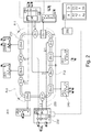
- the figure 2 illustrates a logistics installation 200 according to the invention, comprising, for example, two reception zones ZR, ZR1 and ZR2, for receiving unsorted articles and six dispatch zones ZE, ZE1 to ZE6, for dispatching the sorted articles.
- ZR receiving areas and ZE shipping areas include 230 truck loading docks and 240 truck loading docks, respectively.
- the logistics platform 200 integrates a loop conveyor 210, for example a plate conveyor, comprising six injection zones ZI, ZI-1 to ZI-6, for injecting the articles on the conveyor, the injection zones ZI alternating one by one with six exit zones ZS, ZS-1 to ZS-6, to unload the conveyor.
- a loop conveyor 210 for example a plate conveyor, comprising six injection zones ZI, ZI-1 to ZI-6, for injecting the articles on the conveyor, the injection zones ZI alternating one by one with six exit zones ZS, ZS-1 to ZS-6, to unload the conveyor.
- the arriving articles are separated in this example into three streams 220 of articles pre-sorted by pre-sorting devices PT, PT1 and PT2, at each reception zone ZR, ZR1 and ZR2, that is to say in six streams 220 in total.
- the articles pre-sorted by a given PT pre-sorting device are distributed between three of the injection zones ZI via conveyor lines 330 illustrated in figure 3A .
- Each flow 220 is identified on the figure 2 by a pair of figures p: q, p indicating the pre-sorting device of origin of the stream of pre-sorted articles and q a stream number.
- p is 1 or 2
- q is 1, 2 or 3.
- the injection zones ZI and outlet ZS are distributed along the conveyor in their order of numbering according to the direction S of rotation of the conveyor.
- Each injection zone ZI-i is located upstream of and contiguous to an exit zone ZS-i, i being equal to 1 to 6. In this way, each injection zone is contiguous to and surrounded by two of the zones of ZS outlet and each ZS outlet area is contiguous to and surrounded by two of the ZI injection areas.
- figure 2 illustrates only one particular case, and the number of reception zones ZR and exit ZS is limited only by practical constraints of space and / or economic.
- the PT1 pre-sorting device is connected to the injection zones ZI-1, ZI-3 and ZI-5 , the pre-sorting can be carried out so that the packages injected in ZI-1 are unloaded in ZS-1 or ZS-2, the packages injected in ZI-3 are unloaded in ZS-3 or ZS-4 and the packages injected in ZI-5 are unloaded in ZS-5 or ZS-6, and the PT2 pre-sorting device is connected to the ZI-2, ZI-4 and ZI-6 injection zones, pre-sorting can be carried out so that the packages injected in ZI-2 are unloaded in ZS-2 or ZS-3, packages injected in ZI-4 are unloaded in ZS-4 or ZS-5 and packages injected in ZI-6 are unloaded in ZS-6 or ZS-1.
- each pre-sorting device is connected to a single injection zone every 2 injection zones considered sequentially along the conveyor in
- the loop conveyor is made up of contiguous partitions P two by two, each partition comprising injection zones ZI collectively connected to each of the reception zones by the conveyor lines 330.
- a first partition P-1 comprises, the injection zones ZI-1 and ZI-2
- a second partition P-2 comprises the injection zones ZI-3 and ZI-4
- a third partition P-3 comprises the injection zones ZI-5 and ZI-6.
- each of the partitions P is connected to each of the reception zones ZR1 and ZR2 by the conveyor lines 330.
- the reception areas ZR are equipped with detection and identification devices Id of the articles to detect and identify the articles unloaded from the trucks, and with pre-sorting devices PT to pre-sort the identified articles so as to separate them into three flow 220 according to their identification and a sorting plan prepared in advance.
- Each flow 220 is supported by one or more conveyor lines 330 (depending on the target flow) illustrated by figure 3A .
- Each conveyor line connects one of the PT pre-sorting devices to an injection point in one of the injection zones ZI.
- the detection and identification devices can be optical barcode or square code readers, optical sensors fitted with character recognition systems, or even radio-identification identification chip detectors.
- the figure 3A illustrates a PT pre-sorting device integrated into a ZR reception zone for pre-sorting articles received at the unloading docks 230.
- the articles are placed on conveyors 320 by handling means 310 and then routed on the conveyor lines 330 by routing devices 340.
- the conveyors 320 and the conveyor lines 330 can be, for example, plate conveyors, tape, or roller.
- the handling means can be manual positioning of the articles by operators or automated unloading systems. In this illustration, each of the three flows 1: 1, 1: 2 and 1: 3 is supported by two conveyor lines 330, but this example is not limiting.
- the figure 3B illustrates the exit zones ZI, which include exit points 360 where the articles are discharged from the loop conveyor 340 by exit RT routing devices.
- the routing device is designed to orient the articles towards exits, and may consist, for example, of a device for tilting the trays 340 of the conveyor 210 to drop the articles in receiving bins 350 materializing the exits.
- the bins can be replaced by other types of container or supports such as boxes, pallets, trolleys or shuttles.
- the articles are transported in the bins to the ZE shipping areas where the 240 loading docks are located to be re-shipped by truck.
- a control unit 250 is connected to a database 255 listing g articles A, A1 to Ag, to be sorted in a given period, and associating them with, for example, destinations D, D1 to Dh. G and h represent positive integers.
- the control-command unit 250 is connected to the detection and identification devices Id and controls the pre-sorting devices PT of the reception areas ZR and of the routing devices RT of the exit areas ZS.
- Efficient sorting of articles is based on a good balance of article flow rates between the ZS exit zones. Knowing in advance the articles A to be sorted and their sorting information D, such as destinations, makes it possible to assign the destinations to the sorting output zones and to control the pre-sorting devices of the reception and sorting zones. routing of the exit zones so as to balance the flow rates at the exit zones.
- a protocol for using the logistics platform 200 is as follows, illustrated by the figure 4 .
- a step 410 the data relating to the articles A to be sorted during the period and to their destinations D are received and stored in the database 255.
- control unit 250 accesses the data in the database and draws up a sorting plan for the period according to the volumes of articles to be conveyed to each of the destinations: to each exit zone ZS and exit points 360 are assigned one or more destinations D. This assignment defines the sorting plan.
- the following is a method of assigning item destinations to the output areas based on the number of items to be routed to each destination.
- the destinations are listed in descending order of the number of items to be shipped there.
- 25 D destinations are concerned, they can be classified from 1 to 25, i.e. D01 to D25.
- the destinations are then assigned to the n exit zones of the conveyor by oscillation: the first n destinations are assigned to the n first exit zones, respectively.
- destinations (n + 1) to 2n are assigned to the outputs in the reverse order of the first n departments, and so on.
- destinations 1 to 6 are assigned respectively to exit zones 1 to 6, destinations 7 to 12 to exit zones 6 to 1, destinations 13 to 18 to exit zones 1 to 6, destinations 19 to 24 to exit zones 6 to 1, and destination 25 to exit zone 1.
- the associations formed are then (D01, ZS-1), (D02, ZS-2), (D03, ZS-3), (D04, ZS-4), (D05, ZS-5), (D06, ZS- 6), (D07, ZS-6), (D08, ZS-5), (D09, ZS-4), (D10, ZS-3), (D11, ZS-2), (D12, ZS-1), (D13, ZS-1), (D14, ZS-2), (D15, ZS-3), (D16, ZS-4), (D17 , ZS-5), (D18, ZS-6), (D19, ZS-6), (D20, ZS-5), (D21, ZS-4), (D22, ZS-3), (D23, ZS -2), (D24, ZS-1) and (D25, ZS-1).
- Outbound areas are assigned to destinations before items arrive at the sorting center.
- the articles After their reception in the reception areas ZR during a step 430, the articles are detected and identified by the identification devices Id during a step 440.
- the control-command unit then controls the pre-sorting and routing devices of the exit zones according to the identification of the articles, so that they are routed to the appropriate injection and exit zones. via the conveyor lines during a step 450.
- the sorted articles are conveyed to the shipping areas to be shipped to their destinations, which constitutes step 460.
- the command and control unit 250 is configured so that the assignment of the destinations to the exit zones ZS and the commands of the pre-sorting devices PT of the reception zones ZR and of routing RT of the exit zones ZS are such that an article coming from a given reception zone ZR injected on the conveyor 210 by a first injection zone ZI is discharged from the conveyor 210 before passing through a second injection zone ZI coming from the reception zone ZR reception given.
- articles received in ZR-1 reception area will be injected on the conveyor by one of the injection zones ZI-1, ZI-3 and ZI-5.
- the items injected by the ZI-1 injection area will be unloaded from the conveyor by one of the ZS-1 and ZS-2 exit areas, so that the locations of the conveyor used are freed and can receive a new item through the ZI-3 injection area.
- the articles injected by the ZI-3 injection zone will be unloaded from the conveyor by one of the exit zones ZS-3 and ZS-4, and the articles injected by the ZI-5 injection zone will be unloaded of the conveyor by one of the exit zones ZS-5 and ZS-6.
- the control-command unit controls the pre-sorting devices PT and the routing devices RT of the exit zones ZS so that an article coming from a given ZR reception zone and injected on the conveyor by a first injection zone ZI is unloaded from the conveyor before passing through a second injection zone ZI connected to the reception zone ZR given by l 'one of the conveyor lines 330.
- the present invention presents a way of optimizing loop conveyors integrated in a sorting installation.
Landscapes
- Engineering & Computer Science (AREA)
- Mechanical Engineering (AREA)
- Branching, Merging, And Special Transfer Between Conveyors (AREA)
Description
L'invention se situe dans le domaine de la logistique de transport et de distribution, et plus précisément dans le domaine des infrastructures de tri d'articles comme des lettres ou des colis.The invention is in the field of transport and distribution logistics, and more specifically in the field of infrastructure for sorting articles such as letters or parcels.
Dans le domaine de la logistique, l'efficacité des centres de tri est cruciale pour des questions de vitesse de traitement afin de répondre à la demande, et de rentabilisation des équipements.In the field of logistics, the efficiency of sorting centers is crucial for questions of speed of treatment in order to meet demand, and profitability of equipment.
Les centres de tris comprennent des dispositifs de convoyage dont l'augmentation des débits se heurte à des limites cinématiques : les accélérations et les vitesses possibles sont limitées par la nécessité de conserver les articles sur lesdits dispositifs de convoyage.Sorting centers include conveying devices whose increase in flow rates comes up against kinematic limits: the possible accelerations and speeds are limited by the need to keep the articles on said conveying devices.
En conséquence, la recherche d'augmentation des débits mène à une augmentation de la taille des centres de tri afin d'augmenter leurs capacités, mais aussi à considérer des solutions optimisant leurs architectures et leurs modes d'utilisations en vu de limiter leur emprise au sol et leur coût tout en améliorant leur efficacité.Consequently, the search for increased throughputs leads to an increase in the size of sorting centers in order to increase their capacities, but also to consider solutions optimizing their architectures and their modes of use in view of limiting their footprint to soil and their cost while improving their efficiency.
Un centre de tri peut être construit autour d'un convoyeur en boucle convoyant des articles en série. Le brevet européen
Des articles arrivant au centre de tri sont placés sur le convoyeur en boucle en mouvement au niveau de zones d'injection avant d'être orientés vers une sortie d'une zone de sortie.Items arriving at the sorting center are placed on the moving loop conveyor at the injection zones before being directed towards an exit from an exit zone.
Les articles sont triés en amont du convoyeur en boucle, ou pré-triés, la zone d'injection d'un article donné étant déterminée par sa destination (adresse de livraison) ou tout autre critère de tri, comme sa forme ou son poids. Dans le cas ou le convoyeur comprend deux zones d'injection et deux zones de sortie, cet arrangement permet d'injecter les articles sur des emplacements du convoyeur par une première zone d'injection en amont de la zone de sortie par laquelle ils doivent être déchargés du convoyeur, et de libérer les emplacements avant leur passage au niveau de la seconde zone d'injection.The items are sorted upstream of the loop conveyor, or pre-sorted, the injection area of a given item being determined by its destination (delivery address) or any other sorting criteria, such as its shape or weight. In the case where the conveyor comprises two injection zones and two exit zones, this arrangement makes it possible to inject the articles on locations of the conveyor by a first injection zone upstream from the exit zone through which they must be discharged from the conveyor, and to free up the locations before they pass through the second injection zone.
De cette manière, chaque emplacement du convoyeur peut être utilisé jusqu'à une fois à chaque zone d'injection. Dans le cas où les articles sont séparés en deux flux pré-triés, chaque emplacement pourra être utilisé jusqu'à deux fois par tour.In this way, each location of the conveyor can be used up to once at each injection area. In case the articles are separated into two pre-sorted flows, each location can be used up to twice per turn.
L'objet de l'invention est d'optimiser l'efficacité d'utilisation d'un convoyeur à boucle d'un centre de tri au moyen d'une architecture d'infrastructure de tri d'articles combinant des dispositifs de pré-tri pouvant traiter en parallèle des articles réceptionnés au centre de tri avec l'injection des articles selon une topologie dans laquelle les points d'injection des articles pré-triés par différents dispositifs de pré-tri sont entrelacés, ou alternés.The object of the invention is to optimize the efficiency of use of a loop conveyor of a sorting center by means of an architecture for sorting infrastructure of articles combining pre-sorting devices. being able to process in parallel articles received at the sorting center with the injection of the articles according to a topology in which the injection points of the articles pre-sorted by different pre-sorting devices are interleaved, or alternated.
Plus spécifiquement, une infrastructure de tri selon l'invention permet de séparer, indépendamment pour plusieurs zones de réception comprenant chacune, par exemple, un ou plusieurs quais de déchargement où des articles à trier sont déchargés de camions de livraison, des articles à trier arrivant à ces zones de réception d'articles et à les convoyer jusqu'à des zones d'injection d'un convoyeur en boucle qui sont alternées avec des zones de sortie du convoyeur le long de la boucle formé par celui-ci.More specifically, a sorting infrastructure according to the invention makes it possible to separate, independently for several reception zones each comprising, for example, one or more unloading docks where articles to be sorted are unloaded from delivery trucks, articles to be sorted arriving at these article reception zones and conveying them to injection zones of a loop conveyor which are alternated with exit zones of the conveyor along the loop formed by the latter.
A cet effet, l'invention a pour objet une installation logistique pour trier des articles, comprenant un convoyeur en boucle capable de diriger les articles dans des zones de sortie de tri selon un plan de tri associant les zones de sortie aux articles, le convoyeur en boucle comprenant des zones d'injection chacune agencée pour injecter les articles sur le convoyeur et qui sont alternées une à une avec les zones de sortie, caractérisée en ce que l'installation logistique comprend :
- un certain nombre P de dispositifs de pré-tri prévus pour pré-trier les articles à trier selon ledit plan de tri, P étant un nombre entier supérieur ou égal à deux ;
- des lignes de convoyage des articles pré-triés prévues pour convoyer les articles pré-triés des dispositifs de pré-tri vers les zones d'injection, les lignes de convoyage étant agencées de sorte que chaque zone d'injection est reliée à un seul dispositif de pré-tri et chaque dispositif de pré-tri est relié à plusieurs zones d'injection selon une configuration telle que chaque dispositif de pré-tri est relié à une zone d'injection toutes les P zones d'injection considérées séquentiellement le long du convoyeur dans un sens donné.
- a certain number P of pre-sorting devices provided for pre-sorting the articles to be sorted according to said sorting plan, P being an integer greater than or equal to two;
- conveyor lines for the pre-sorted articles intended to convey the pre-sorted articles from the pre-sorting devices to the injection zones, the conveyor lines being arranged so that each injection zone is connected to a single device pre-sorting and each pre-sorting device is connected to several injection zones in a configuration such that each pre-sorting device is connected to an injection zone all the P injection zones considered sequentially along the conveyor in a given direction.
Avec cette architecture d'infrastructure et la connaissance à l'avance des articles à trier et des informations de tri associées à ces articles, on peut optimiser l'utilisation du convoyeur en répartissant de façon équilibrée les flux d'articles vers les zones d'injection et les zones de sortie.With this infrastructure architecture and the advance knowledge of the items to be sorted and the sorting information associated with these items, we can optimize the use of the conveyor by distributing the item flows in a balanced manner to the injection and exit areas.
En particulier, selon l'invention, on peut prévoir une unité de contrôle-commande agencée pour calculer, à partir de la connaissance à l'avance des articles à trier et des informations de tri associées à ces articles, par exemple sous forme de données archivées dans une base de données accessible par l'unité de contrôle-commande, une répartition optimisée des articles pré-triés dans les lignes de convoyage de manière à équilibrer des débits d'articles entre les zones de sortie tout en imposant une contrainte selon laquelle un article injecté sur le convoyeur depuis un dispositif de pré-tri donné relié à plusieurs zones d'injection par des lignes de convoyages correspondantes, qui est injecté sur le convoyeur depuis une certaine zone d'injection reliée audit dispositif de pré-tri donné, est déchargé du convoyeur avant de traverser une autre zone d'injection qui est reliée audit dispositif de pré-tri donné.In particular, according to the invention, it is possible to provide a control-command unit arranged to calculate, from the advance knowledge of the articles to be sorted and sorting information associated with these articles, for example in the form of data. archived in a database accessible by the control-command unit, an optimized distribution of the pre-sorted articles in the conveyor lines so as to balance the flow rates of articles between the exit zones while imposing a constraint according to which an article injected onto the conveyor from a given pre-sorting device connected to several injection zones by corresponding conveyor lines, which is injected onto the conveyor from a certain injection zone connected to said given pre-sorting device, is discharged from the conveyor before passing through another injection zone which is connected to said given pre-sorting device.
L'invention peut avantageusement présenter encore les particularités suivantes :
- les informations de tri sont des adresses de livraison,
- le convoyeur en boucle est constitué de partitions reliées bout à bout, chaque partition comprenant un même nombre de zones d'injection et de zones de sortie, les zones d'injection de chaque partition étant collectivement reliées à chacune des zones de réception par les lignes de convoyage,
- chaque dispositif de pré-tri est prévu pour séparer les articles non triés en Q flux d'articles pré-triés convoyés par les lignes de convoyage, Q étant un nombre entier supérieur ou égal à 2, le convoyeur en boucle comprend I zones d'injection avec I = P × Q, les zones d'injection étant numérotées de 1 à I et disposées dans cet ordre autour du convoyeur selon un sens S de rotation du convoyeur, et un flux numéroté q avec q variant de 1 à Q part d'un dispositif de pré-tri numéroté p avec p variant de 1 à P et aboutit à la zone d'injection i avec i = p + (P × (q-1)),
- le convoyeur en boucle est un convoyeur à plateaux,
- les articles sont des articles de courrier ou des colis.
- sorting information is delivery address,
- the loop conveyor consists of partitions connected end to end, each partition comprising the same number of injection zones and output zones, the injection zones of each partition being collectively connected to each of the reception zones by conveyor lines,
- each pre-sorting device is designed to separate the unsorted articles into Q flow of pre-sorted articles conveyed by the conveyor lines, Q being an integer greater than or equal to 2, the loop conveyor comprises I zones of injection with I = P × Q, the injection zones being numbered from 1 to I and arranged in this order around the conveyor in a direction S of rotation of the conveyor, and a flow numbered q with q varying from 1 to Q part d '' a pre-sorting device numbered p with p varying from 1 to P and ends at the injection zone i with i = p + (P × (q-1)),
- the loop conveyor is a plate conveyor,
- the items are mail items or packages.
La présente invention sera mieux comprise et d'autres avantages apparaîtront à la lecture de la description détaillée d'un mode de réalisation pris à titre d'exemple nullement limitatif et illustré par les dessins annexés, dans lesquels :
- la
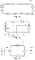
figure 1A représente une architecture d'une installation de tri avec un convoyeur en boucle comprenant des zones d'injection en alternance avec des zones de sortie; - la
figure 1B représente une architecture d'une installation de tri avec un convoyeur en boucle pouvant être utilisée avec une méthode de séparation des articles à trier en flux d'articles pré-triés ; - la
figure 1C représente une architecture d'une installation de tri avec un convoyeur en boucle pouvant être utilisée avec une méthode d'entrelacement de zones d'injection et de zones de sortie d'articles à trier réceptionnés à deux zones de réception ;
- la
figure 2 représente une installation de tri avec un convoyeur en boucle selon l'invention, avec deux zones de réception, séparation des articles à trier en deux flux pré-triés par zone de réception, et entrelacement de zones d'injection et de zones de sortie d'articles à trier réceptionnés aux deux zones de réception ; - la
figure 3A représente une zone de réception de lafigure 2 et le dispositif de pré-tri associé ; - la
figure 3B représente des portions d'une zone de sortie et d'une zone d'injection du convoyeur en boucle de lafigure 2 ; et - la
figure 4 représente des étapes d'une méthode de tri employant l'installation de tri de lafigure 2 .
- the
figure 1A represents an architecture of a sorting installation with a loop conveyor comprising injection zones alternating with exit zones; - the
figure 1B represents an architecture of a sorting installation with a loop conveyor which can be used with a method of separating the articles to be sorted into a stream of pre-sorted articles; - the
figure 1C represents an architecture of a sorting installation with a loop conveyor which can be used with a method of interleaving injection zones and exit zones of articles to be sorted received with two reception zones;
- the
figure 2 represents a sorting installation with a loop conveyor according to the invention, with two reception zones, separation of the articles to be sorted into two pre-sorted flows per reception zone, and interleaving of injection zones and exit zones d 'items to be sorted received at the two reception areas; - the
figure 3A represents a reception area of thefigure 2 and the associated pre-sorting device; - the
figure 3B represents portions of an exit zone and an injection zone of the loop conveyor of thefigure 2 ; and - the
figure 4 represents steps of a sorting method employing the sorting facility of thefigure 2 .
Le but de l'invention est d'améliorer l'efficacité d'un centre de tri en augmentant le débit opérationnel Do d'un convoyeur en boucle qui dépend i) du débit mécanique du convoyeur Dm, fixé par ses caractéristiques physiques (dimensions, vitesse), et ii) du nombre d'utilisations par tour d'un emplacement du convoyeur, représenté par le multiplicateur M.The object of the invention is to improve the efficiency of a sorting center by increasing the operational flow rate Do of a loop conveyor which depends on i) the mechanical flow rate of the conveyor Dm, fixed by its physical characteristics (dimensions, speed), and ii) the number of uses per revolution of a conveyor location, represented by the multiplier M.
Le débit opérationnel est défini comme la multiplication du débit mécanique D du convoyeur par le multiplicateur M : Do = Dm × M. M est une valeur opérationnelle, dépendant du mode d'utilisation du convoyeur, et non une valeur uniquement fixée par la topologie des éléments du centre de tri.The operational flow is defined as the multiplication of the mechanical flow D of the conveyor by the multiplier M: Do = Dm × M. M is an operational value, depending on the mode of use of the conveyor, and not a value only fixed by the topology of the elements of the sorting center.
M dépend à la fois de l'architecture du centre et de la façon dont celui-ci est opéré. Pour atteindre son but, l'invention passe par une architecture permettant d'obtenir des multiplicateurs M significativement plus élevés que les architectures conventionnelles.M depends both on the architecture of the center and on the way it is operated. To achieve its goal, the invention goes through an architecture making it possible to obtain multipliers M significantly higher than conventional architectures.
Ceci permet d'augmenter la capacité opérationnelle du convoyeur à caractéristiques mécaniques constantes.This increases the operational capacity of the conveyor with constant mechanical characteristics.
Afin d'analyser les multiplicateurs d'une architecture donnée, il est nécessaire de décrire de manière formelle un système comprenant un convoyeur en boucle comprenant n zones d'injection alternées avec le même nombre de zones de sortie. La
Les zones d'injection et les zones de sortie sont représentées par ZI et ZS, respectivement, numérotées de 1 à 6, et réparties le long de la boucle formée par le convoyeur selon leur numéro dans le sens de rotation S.The injection zones and the exit zones are represented by ZI and ZS, respectively, numbered from 1 to 6, and distributed along the loop formed by the conveyor according to their number in the direction of rotation S.
Dans ce système, soient :
- M le multiplicateur du système
- d(i) le débit d'injection maximal possible de la zone d'injection i (i valant de 1 à n)
- α (i,j) la proportion du flux d'articles injecté par la zone d'injection i à destination de la zone de sortie j (j valant de 1 à n),
- M the system multiplier
- d (i) the maximum possible injection rate of the injection zone i (i being from 1 to n)
- α (i, j) the proportion of the flow of articles injected by the injection zone i bound for the exit zone j (j being 1 to n),
Nous avons alors 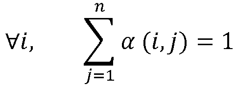

Les coefficients α (i,j) sont des données d'exploitation du système : ils dépendent de la structure des flux traités et de leur répartition entre les zones de sortie. Pour une utilisation optimale du convoyeur, les opérations du système doivent être configurées pour mener à une équi-distribution des volumes entre les différentes zones de sortie, et on aura alors ![]()
![]()
Un bilan du trafic en chaque point Pj situé entre la zone d'injection j et la zone de sortie j avec j variant de 1 à n peut être établi.A traffic balance at each point P j located between the injection area j and the exit area j with j varying from 1 to n can be established.
Les plateaux du trieur sont occupés par les objets injectés à chaque zone d'injection injection i (de 1 à n) et non encore libérés au passage en Pj. Soit o(i,j) la proportion des plateaux chargés à la zone d'injection i et encore occupés au passage du point Pj. Par définition ![]()
![]()
![]()
![]()
![]()
![]()
![]()
![]()
Le débit maximal du système est atteint lorsque le débit du trieur est maximal après chaque zone d'injection (en chaque point Pj ci-dessus).The maximum system flow is reached when the sorter flow is maximum after each injection zone (at each point P j above).
Un système de n relations dont les inconnues sont les d(j) avec j variant de 1 à n et dont les coefficients sont construits avec les α (i,j) paramètres d'entrées du système est établi: 

Le multiplicateur M est entièrement déterminé par la matrice A des α(i,j). Dans le cas particulier de la 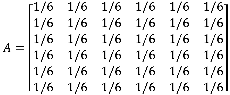
La résolution de ce système de relations donne d(1) = d(2) = d(3) = d(4) = d(5) = d(6) = 2/7 D et M = 1,714. Dans cet exemple, un plateau recevant un article injecté dans la zone d'injection 1 et déchargé dans la zone de sortie 6, soit le cas d'un article sur six, n'est utilisé qu'une seule fois dans le tour ; un plateau recevant de même un article injecté dans la zone d'injection 1 et déchargé dans la zone de sortie 1 sera utilisé au moins deux fois.The resolution of this system of relations gives d (1) = d (2) = d (3) = d (4) = d (5) = d (6) = 2/7 D and M = 1,714. In this example, a tray receiving an article injected into the
La méthode du document de brevet
Les articles arrivants sont séparés en n flux pré-triés de tailles identiques à destination de n zones de sortie correspondantes d'un convoyeur en boucle via n zones d'injection correspondantes du convoyeur, chacune des zones d'injection étant située entre deux zones de sortie adjacentes.Incoming items are separated into n pre-sorted flows of identical sizes destined for n corresponding exit zones of a loop conveyor via n corresponding injection zones of the conveyor, each of the injection zones being situated between two adjacent exit zones.
Selon cette méthode, les articles injectés par une même zone d'injection sont en totalité évacués du convoyeur par une même zone de sortie.According to this method, the articles injected by the same injection zone are entirely evacuated from the conveyor by the same exit zone.
La
Le pré-tri est effectué de manière à ce que chaque emplacement du convoyeur chargé par une ligne d'injection dans une zone d'injection ZI soit libéré au niveau d'une zone de sortie avant d'être présenté à la zone d'injection ZI suivante. Plus précisément, les articles sont pré-triés de manière à ce qu'un article à destination d'une sortie de la zone de sortie i sera injecté sur le convoyeur via la zone d'injection i, située en amont de et contigüe à la zone de sortie i, pour i valant 1, 2, ou 3.The pre-sorting is carried out so that each location of the conveyor loaded by an injection line in an injection zone ZI is released at an exit zone before being presented to the injection zone Next ZI. More specifically, the articles are pre-sorted so that an article destined for an exit from the exit zone i will be injected onto the conveyor via the injection zone i, located upstream of and contiguous to the exit zone i, for i equal to 1, 2, or 3.
Dans le formalisme utilisé plus haut, la matrice A s'exprime par 
Une autre architecture consiste à alimenter un convoyeur par au moins deux zones de réception en parallèle et à entrelacer, ou alterner, les zones de sortie et les zones d'injection correspondantes.Another architecture consists in supplying a conveyor by at least two receiving zones in parallel and interleaving, or alternating, the output zones and the corresponding injection zones.
Une telle architecture est illustrée par la
Une situation idéale, dans laquelle les articles sont naturellement (sans pré-tri) répartis entre chacune des zones de sortie indépendamment de leur zone de réception, une équi-distribution des articles entre les zones d'injection et entre les zones de sortie est obtenue.An ideal situation, in which the articles are naturally (without pre-sorting) distributed between each of the exit zones independently of their reception zone, an equal distribution of the articles between the injection zones and between the exit zones is obtained .
Dans le formalisme utilisé plus haut, la matrice A s'exprime par ![]()
![]()
L'invention a pour but de combiner la méthode de séparation des flux avec la méthode d'entrelacement des zones d'injection et de sortie de plusieurs zones de réception, et ce de manière à combiner les avantages, et les multiplicateurs M, de chacune des méthodes. Les inventeurs ont déterminé une architecture permettant cette combinaison.The object of the invention is to combine the method of separating the flows with the method of interleaving the injection and exit zones of several reception zones, so as to combine the advantages, and the multipliers M, of each methods. The inventors have determined an architecture allowing this combination.
Selon l'invention, une installation logistique de traitement d'articles à trier comprend un convoyeur en boucle pour convoyer des articles à trier selon un plan de circulation en boucle, le convoyeur comprenant autant de zones d'injection que de zones de sortie.According to the invention, a logistic installation for processing articles to be sorted comprises a loop conveyor for conveying articles to be sorted according to a loop circulation plan, the conveyor comprising as many injection zones as exit zones.
La
Les zones de réception ZR et les zones d'expédition ZE comprennent des quais de déchargement 230 de camions et des quais de chargement 240 de camions, respectivement.ZR receiving areas and ZE shipping areas include 230 truck loading docks and 240 truck loading docks, respectively.
La plate-forme logistique 200 intègre un convoyeur en boucle 210, par exemple un convoyeur à plateaux, comprenant six zones d'injection ZI, ZI-1 à ZI-6, pour injecter les articles sur le convoyeur, les zones d'injection ZI alternant une à une avec six zones de sortie ZS, ZS-1 à ZS-6, pour décharger le convoyeur.The
Les articles arrivant sont séparés dans cet exemple en trois flux 220 d'articles pré-triés par des dispositifs de pré-tri PT, PT1 et PT2, à chaque zone de réception ZR, ZR1 et ZR2, soit en six flux 220 au total. Les articles pré-triés par un dispositif de pré-tri PT donné sont répartis entre trois des zones d'injection ZI via des lignes de convoyage 330 illustrées en
Chaque flux 220 est identifié sur la
Les zones d'injection ZI et de sortie ZS sont réparties le long du convoyeur dans leur ordre de numérotation selon le sens S de rotation du convoyeur.The injection zones ZI and outlet ZS are distributed along the conveyor in their order of numbering according to the direction S of rotation of the conveyor.
Chaque zone d'injection ZI-i est située en amont de et contigüe à une zone de sortie ZS-i, i valant de 1 à 6. De cette manière, chaque zone d'injection est contigüe à et entourée par deux des zones de sortie ZS et chaque zone de sortie ZS est contigüe à et entourée par deux des zones d'injection ZI.Each injection zone ZI-i is located upstream of and contiguous to an exit zone ZS-i, i being equal to 1 to 6. In this way, each injection zone is contiguous to and surrounded by two of the zones of ZS outlet and each ZS outlet area is contiguous to and surrounded by two of the ZI injection areas.
Le terme « contigüe » ne s'applique dans ce document qu'aux éléments ZI et ZS de l'invention, et n'exclut pas la présence d'éléments non liés à l'invention entre deux de ces éléments dits « contigües » sur le convoyeur.The term "contiguous" in this document only applies to elements ZI and ZS of the invention, and does not exclude the presence of elements not related to the invention between two of these elements called "contiguous" on the conveyor.
De plus, La
Dans la
Ainsi, dans le cas de la
Le convoyeur en boucle est constitué de partitions P contigües deux à deux, chaque partition comprenant des zones d'injection ZI collectivement reliées à chacune des zones de réception par les lignes de convoyage 330.The loop conveyor is made up of contiguous partitions P two by two, each partition comprising injection zones ZI collectively connected to each of the reception zones by the conveyor lines 330.
Dans la
Les zones de réceptions ZR sont équipées de dispositifs de détection et d'identification Id des articles pour détecter et identifier les articles déchargés des camions, et de dispositifs de pré-tri PT pour pré-trier les articles identifiés de manière à les séparer en trois flux 220 en fonction de leur identification et d'un plan de tri préparé à l'avance.The reception areas ZR are equipped with detection and identification devices Id of the articles to detect and identify the articles unloaded from the trucks, and with pre-sorting devices PT to pre-sort the identified articles so as to separate them into three
Chaque flux 220 est pris en charge par une ou plusieurs lignes de convoyage 330 (selon le débit visé) illustrées par la
La
Les articles sont placés sur des convoyeurs 320 par des moyens de manutention 310 puis routés sur les lignes de convoyages 330 par des dispositifs de routage 340. Les convoyeurs 320 et les lignes de convoyage 330 peuvent être, par exemple, des convoyeurs à plateaux, à bande, ou à rouleaux. Les moyens de manutention peuvent être un positionnement manuel des articles par des opérateurs ou des systèmes de déchargement automatisés. Dans cette illustration, chacun des trois flux 1:1, 1:2 et 1:3 est pris en charge par deux lignes de convoyage 330, mais cet exemple n'est pas limitatif.The articles are placed on
La
Le dispositif de routage est conçu pour orienter les articles vers des sorties, et peuvent consister par exemple en un dispositif de basculement des plateaux 340 du convoyeur 210 pour faire chuter les articles dans des bacs de réception 350 matérialisant les sorties. Les bacs peuvent être remplacés par d'autres types de contenant ou de supports tels que des cartons, palettes, chariots ou navettes.The routing device is designed to orient the articles towards exits, and may consist, for example, of a device for tilting the
Après le tri, les articles sont transportés dans les bacs jusqu'aux zones d'expédition ZE où sont situés les quais de chargement 240 pour être réexpédiés par camion.After sorting, the articles are transported in the bins to the ZE shipping areas where the 240 loading docks are located to be re-shipped by truck.
Une unité de contrôle-commande 250 est connectée à une base de donnée 255 listant g articles A, A1 à Ag, à trier dans une période donnée, et les associant à, par exemple, des destinations D, D1 à Dh. G et h représentent des nombres entiers positifs.A
L'unité de contrôle-commande 250 est reliée aux dispositifs de détection et d'identification Id et commande les dispositifs de pré-tri PT des zones de réception ZR et des dispositifs de routage RT des zones de sortie ZS.The control-
Un tri efficace des articles repose sur un bon équilibre des débits d'articles entre les zones de sortie ZS. La connaissance à l'avance des articles A à trier et de leurs informations de tri D, telles des destinations, permet d'affecter les destinations aux zones de sortie de tri et de commander les dispositifs de pré-tri des zones de réception et de routage des zones de sortie de manière à équilibrer les débits aux zones de sortie.Efficient sorting of articles is based on a good balance of article flow rates between the ZS exit zones. Knowing in advance the articles A to be sorted and their sorting information D, such as destinations, makes it possible to assign the destinations to the sorting output zones and to control the pre-sorting devices of the reception and sorting zones. routing of the exit zones so as to balance the flow rates at the exit zones.
Bien entendu, d'autres critères que les destinations peuvent être utilisés pour procéder au tri.Of course, other criteria than destinations can be used to sort.
Pour une période donnée, un protocole d'utilisation de la plate-forme logistique 200 est le suivant, illustré par la
Dans une étape 410 les données relatives aux articles A à trier au cours de la période et à leurs destinations D sont reçues et stockées dans la base de données 255.In a
Dans une étape 420, l'unité de contrôle-commande 250 accède aux données de la base de données et élabore un plan de tri pour la période en fonction des volumes d'articles à acheminer à chacune des destinations : à chaque zone de sortie ZS et points de sortie 360 sont affectées une ou plusieurs destinations D. Cette affectation définit le plan de tri.In a
Une méthode d'affectation des destinations des articles aux zones de sortie en fonction du nombre d'articles à acheminer à chaque destination est la suivante.The following is a method of assigning item destinations to the output areas based on the number of items to be routed to each destination.
Tout d'abord, les destinations sont classées par ordre décroissant du nombre d'articles devant y être acheminés.First, the destinations are listed in descending order of the number of items to be shipped there.
Si 25 destinations D sont concernées, elles peuvent être ainsi classées de 1 à 25, soit D01 à D25. Les destinations sont alors affectées aux n zones de sortie du convoyeur par oscillation : les n premières destinations sont assignées aux n premières zones de sortie, respectivement.If 25 D destinations are concerned, they can be classified from 1 to 25, i.e. D01 to D25. The destinations are then assigned to the n exit zones of the conveyor by oscillation: the first n destinations are assigned to the n first exit zones, respectively.
Les destinations (n+1) à 2n sont affectées aux sorties dans l'ordre inverse des n premiers départements, et ainsi de suite. Dans le cas illustré en
Les associations formées sont alors(D01, ZS-1), (D02, ZS-2), (D03, ZS-3), (D04, ZS-4), (D05, ZS-5), (D06, ZS-6), (D07, ZS-6), (D08, ZS-5), (D09, ZS-4), (D10, ZS-3), (D11, ZS-2), (D12, ZS-1), (D13, ZS-1), (D14, ZS-2), (D15, ZS-3), (D16, ZS-4), (D17, ZS-5), (D18, ZS-6), (D19, ZS-6), (D20, ZS-5), (D21, ZS-4), (D22, ZS-3), (D23, ZS-2), (D24, ZS-1) et (D25, ZS-1).The associations formed are then (D01, ZS-1), (D02, ZS-2), (D03, ZS-3), (D04, ZS-4), (D05, ZS-5), (D06, ZS- 6), (D07, ZS-6), (D08, ZS-5), (D09, ZS-4), (D10, ZS-3), (D11, ZS-2), (D12, ZS-1), (D13, ZS-1), (D14, ZS-2), (D15, ZS-3), (D16, ZS-4), (D17 , ZS-5), (D18, ZS-6), (D19, ZS-6), (D20, ZS-5), (D21, ZS-4), (D22, ZS-3), (D23, ZS -2), (D24, ZS-1) and (D25, ZS-1).
Les zones de sortie sont affectées aux destinations avant l'arrivée des articles au centre de tri.Outbound areas are assigned to destinations before items arrive at the sorting center.
Après leur réception dans les zones de réceptions ZR au cours d'une étape 430, les articles sont détectés et identifiés par les dispositifs d'identification Id au cours d'une étape 440.After their reception in the reception areas ZR during a
L'unité de contrôle-commande commande alors les dispositifs de pré-tri et de routage des zones de sortie en fonction de l'identification des articles, de manière à ce qu'ils soient acheminés vers les zones d'injection et de sortie adéquates via les lignes de convoyage au cours d'une étape 450. Les articles triés sont convoyés jusqu'aux zones d'expédition pour être expédiés à leurs destinations, ce qui constitue l'étape 460.The control-command unit then controls the pre-sorting and routing devices of the exit zones according to the identification of the articles, so that they are routed to the appropriate injection and exit zones. via the conveyor lines during a
Selon l'invention, l'unité de contrôle commande 250 est configurée de sorte que l'affectation des destinations aux zones de sortie ZS et les commandes des dispositifs de pré-tri PT des zones de réception ZR et de routage RT des zones de sortie ZS sont telles qu'un article en provenance d'une zone de réception ZR donnée injecté sur le convoyeur 210 par une première zone d'injection ZI est déchargé du convoyeur 210 avant de traverser une seconde zone d'injection ZI provenant de la zone de réception ZR donnée.According to the invention, the command and
De plus, les débits d'articles dans les zones de sortie ZS doivent être équilibrés.In addition, the material flow rates in the ZS exit areas must be balanced.
Dans l'exemple illustré par la
De même, les articles injectés par la zone d'injection ZI-3 seront déchargés du convoyeur par l'une des zones de sorties ZS-3 et ZS-4, et les articles injectés par la zone d'injection ZI-5 seront déchargés du convoyeur par l'une des zones de sorties ZS-5 et ZS-6. Généralisé au cas d'un nombre n de zones de sortie et de zones d'entrée, l'unité de contrôle-commande commande les dispositifs de pré-tri PT et les dispositifs de routage RT des zones de sortie ZS de manière à ce qu'un article en provenance d'une zone de réception ZR donnée et injecté sur le convoyeur par une première zone d'injection ZI est déchargé du convoyeur avant de traverser une seconde zone d'injection ZI connectée à la zone de réception ZR donnée par l'une des lignes de convoyage 330.Likewise, the articles injected by the ZI-3 injection zone will be unloaded from the conveyor by one of the exit zones ZS-3 and ZS-4, and the articles injected by the ZI-5 injection zone will be unloaded of the conveyor by one of the exit zones ZS-5 and ZS-6. Generalized in the case of a number n of exit zones and entry zones, the control-command unit controls the pre-sorting devices PT and the routing devices RT of the exit zones ZS so that an article coming from a given ZR reception zone and injected on the conveyor by a first injection zone ZI is unloaded from the conveyor before passing through a second injection zone ZI connected to the reception zone ZR given by l 'one of the conveyor lines 330.
En utilisant le formalisme expliqué plus haut, la matrice A correspondant à cette architecture et à cette méthode d'opération est la suivante : 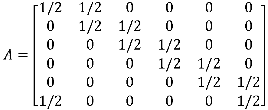
Le multiplicateur M3 = 4 de cette configuration à deux zones de réception et trois flux pré-triés par zone de réception est égal au produit du multiplicateur M1 = 3 de la configuration à une zone de réception et trois flux pré-triés et du multiplicateur M2 = 4/3 de la configuration à deux zones de réception avec entrelacement des zones d'injection et de sortie.Multiplier M3 = 4 of this configuration with two reception zones and three pre-sorted flows per zone reception is equal to the product of the multiplier M1 = 3 of the configuration with one reception zone and three pre-sorted flows and of the multiplier M2 = 4/3 of the configuration with two reception zones with interleaving of the injection and exit.
Par cette architecture, combinant pré-tri et entrelacement, les multiplicateurs d'architectures avec pré-tri et entrelacement sont multipliés entre eux.By this architecture, combining pre-sorting and interleaving, the architecture multipliers with pre-sorting and interleaving are multiplied between them.
Ainsi, la présente invention présente une voie d'optimisation des convoyeurs à boucle intégrés dans une installation de tri.Thus, the present invention presents a way of optimizing loop conveyors integrated in a sorting installation.
Claims (7)
- A logistics installation (200) for sorting articles, the installation including a looped conveyor (210) capable of directing the articles into sorting outlet zones (ZS, ZS-1, ZS-2, ZS-3, ZS-4, ZS-5, ZS-6) according to sorting plan that associates the outlet zones with the articles, the looped conveyor having injection zones (ZI, ZI-1, ZI-2, ZI-3, ZI-4, ZI-5, ZI-6), each of which is arranged to inject the articles onto the conveyor and which alternate with the outlet zones, said logistics installation being characterized in that it further includes:• a certain number P of pre-sorting devices (PT1, PT2) designed for pre-sorting the articles to be sorted according to said sorting plan, P being an integer greater than or equal to two; and• conveyor lines (330) for conveying the pre-sorted articles from the pre-sorting devices to the injection zones, the conveyor lines being arranged so that each injection zone is connected to one pre-sorting device only and each pre-sorting device is connected to a plurality of injection zones in a configuration in which each pre-sorting device is connected to one in every P injection zones considered sequentially along the conveyor in a given direction.
- A logistics installation according to claim 1, characterized in that the installation further includes a monitoring and control unit (250) arranged to act on the basis of advance knowledge of the articles (A) to be sorted and of the sorting information (D) associated with said articles to compute an optimized distribution for the pre-sorted articles in the conveyor lines (330) in such a manner as to balance the article throughput rates between the outlet zones (ZS, ZS-1, ZS-2, ZS-3, ZS-4, ZS-5, ZS-6) while also imposing a constraint whereby an article injected onto the conveyor from a given pre-sorting device (PT, PT1, PT2) connected to a plurality of injection zones (ZI, ZI-1, ZI-2, ZI-3, ZI-4, ZI-5, ZI-6) via the corresponding conveyor lines, which article is injected onto the conveyor (210) from a certain injection zone connected to said given pre-sorting device, is unloaded from the conveyor before going through another injection zone that is connected to said given pre-sorting device.
- A logistics installation according to any preceding claim, characterized in that the sorting information (D) is constituted by delivery addresses.
- A logistics installation according to any preceding claim, characterized in that the looped conveyor is made up of subdivisions (P-1, P-2, P-3) that are connected together end-to-end, each subdivision including the same number of injection zones (ZI, ZI-1, ZI-2, ZI-3, ZI-4, ZI-5, ZI-6) and of outlet zones (ZS, ZS-1, ZS-2, ZS-3, ZS-4, ZS-5, ZS-6), the injection zones of each subdivision being collectively connected to each of the article-receiving zones (ZR1, ZR2) via the conveyor lines (330).
- A logistics installation according to any preceding claim, characterized in that:• each pre-sorting device (PT) is designed to separate the non-sorted articles into Q streams (220) of pre-sorted articles conveyed by the conveyor lines (330), where Q is an integer greater than or equal to 2;• the looped conveyor includes I injection zones, where I = P × Q, the injection zones being numbered from 1 to I and being disposed in that order around the conveyor in a direction S of rotation of the conveyor; and• a stream (220) numbered q, where q lies in the range 1 to Q, goes from a pre-sorting device numbered p, where p lies in the range 1 to P, and leads to the injection zone i, where i = p + (P × (q-1)).
- A logistics installation according to any preceding claim, characterized in that the looped conveyor is a platform conveyor.
- A logistics installation according to any preceding claim, characterized in that the articles are mailpieces or parcels.
Applications Claiming Priority (1)
| Application Number | Priority Date | Filing Date | Title |
|---|---|---|---|
| FR1759245A FR3071753B1 (en) | 2017-10-03 | 2017-10-03 | ARCHITECTURE OF A SORTING CENTER COMPRISING A LOOP CONVEYOR |
Publications (2)
| Publication Number | Publication Date |
|---|---|
| EP3466552A1 EP3466552A1 (en) | 2019-04-10 |
| EP3466552B1 true EP3466552B1 (en) | 2020-03-25 |
Family
ID=60765826
Family Applications (1)
| Application Number | Title | Priority Date | Filing Date |
|---|---|---|---|
| EP18188485.9A Active EP3466552B1 (en) | 2017-10-03 | 2018-08-10 | Architecture of a sorting centre comprising a loop conveyor |
Country Status (3)
| Country | Link |
|---|---|
| US (1) | US10479617B2 (en) |
| EP (1) | EP3466552B1 (en) |
| FR (1) | FR3071753B1 (en) |
Family Cites Families (4)
| Publication number | Priority date | Publication date | Assignee | Title |
|---|---|---|---|---|
| US6323452B1 (en) * | 1999-08-05 | 2001-11-27 | United Parcel Service Of America, Inc. | Feeding system and method for placing a plurality of objects on a tray of an automated sorting system |
| US6978192B2 (en) * | 2004-04-02 | 2005-12-20 | Lockheed Martin Corporation | Single pass sequencer and method of use |
| EP1993944A4 (en) * | 2006-02-24 | 2009-04-08 | Northrop Grumman Systems Corp | Process for sorting objects |
| EP3147038A1 (en) * | 2015-09-25 | 2017-03-29 | Siemens Aktiengesellschaft | Distributing and sorting center for sorted items and method for operating a distributing and sorting center for sorted items |
-
2017
- 2017-10-03 FR FR1759245A patent/FR3071753B1/en not_active Expired - Fee Related
-
2018
- 2018-08-10 EP EP18188485.9A patent/EP3466552B1/en active Active
- 2018-10-02 US US16/149,394 patent/US10479617B2/en active Active
Non-Patent Citations (1)
| Title |
|---|
| None * |
Also Published As
| Publication number | Publication date |
|---|---|
| FR3071753B1 (en) | 2019-09-27 |
| EP3466552A1 (en) | 2019-04-10 |
| FR3071753A1 (en) | 2019-04-05 |
| US10479617B2 (en) | 2019-11-19 |
| US20190100388A1 (en) | 2019-04-04 |
Similar Documents
| Publication | Publication Date | Title |
|---|---|---|
| US10967405B2 (en) | Systems and methods for high throughput sorting | |
| US10758943B1 (en) | Container-based material handling for automatic parcel sacking system | |
| US10040642B2 (en) | Multiple speed conveyor storage system | |
| CN107472852B (en) | Delivery vehicle and method for delivering shipments at different locations of a delivery route | |
| RU2765392C1 (en) | System of selection of goods on order containing a continuous conveyor and method for application of such system | |
| CN109641701A (en) | With the order fulfillment system and method background technique for arranging and sorting function | |
| KR20170020901A (en) | Parcel sorter system and method | |
| FR2996788A1 (en) | PACKAGE PROCESSING METHOD AND LOGISTIC PACKAGE PROCESSING CENTER | |
| KR20200102577A (en) | Automatic classifying system and method for goods based on delivery unit of goods | |
| US12280401B2 (en) | Sequencing parcel sorter | |
| WO2023058446A1 (en) | Package conveying device and package supply device | |
| CN110248882A (en) | Balancing load between operating system regions | |
| CN204276368U (en) | Sorting device with two storage areas | |
| EP3466552B1 (en) | Architecture of a sorting centre comprising a loop conveyor | |
| EP1722900B1 (en) | Method and device for preparing a postman's route with both letters and large format objects | |
| US10722920B2 (en) | Device and method for delivery point sorting | |
| EP3107663A1 (en) | Method for the postal sorting of small streams of mail | |
| KR101762883B1 (en) | dual-type carrier system for high speed goods auto-classification machine | |
| WO2017017605A1 (en) | Automatic system and method for managing internal logistics for handling products in stackable containers | |
| US20240262625A1 (en) | Multi-level sorting system | |
| EP2569099B1 (en) | Method for improving a process for treatment and transport of postal articles in containers, using batch sorting | |
| EP3722012B1 (en) | Pooling of outputs of parcel sorters | |
| US11772908B1 (en) | Automated item picking stations | |
| CN114945957B (en) | Controlling a system for processing valuable items and preparing/outputting valuable item packages | |
| RU2850424C1 (en) | System control for processing valuables and for individualised packaging and/or dispensing of valuable item packages |
Legal Events
| Date | Code | Title | Description |
|---|---|---|---|
| PUAI | Public reference made under article 153(3) epc to a published international application that has entered the european phase |
Free format text: ORIGINAL CODE: 0009012 |
|
| STAA | Information on the status of an ep patent application or granted ep patent |
Free format text: STATUS: THE APPLICATION HAS BEEN PUBLISHED |
|
| AK | Designated contracting states |
Kind code of ref document: A1 Designated state(s): AL AT BE BG CH CY CZ DE DK EE ES FI FR GB GR HR HU IE IS IT LI LT LU LV MC MK MT NL NO PL PT RO RS SE SI SK SM TR |
|
| AX | Request for extension of the european patent |
Extension state: BA ME |
|
| STAA | Information on the status of an ep patent application or granted ep patent |
Free format text: STATUS: REQUEST FOR EXAMINATION WAS MADE |
|
| RBV | Designated contracting states (corrected) |
Designated state(s): AL AT BE BG CH CY CZ DE DK EE ES FI FR GB GR HR HU IE IS IT LI LT LU LV MC MK MT NL NO PL PT RO RS SE SI SK SM TR |
|
| 17P | Request for examination filed |
Effective date: 20190527 |
|
| RBV | Designated contracting states (corrected) |
Designated state(s): AL AT BE BG CH CY CZ DE DK EE ES FI FR GB GR HR HU IE IS IT LI LT LU LV MC MK MT NL NO PL PT RO RS SE SI SK SM TR |
|
| GRAP | Despatch of communication of intention to grant a patent |
Free format text: ORIGINAL CODE: EPIDOSNIGR1 |
|
| STAA | Information on the status of an ep patent application or granted ep patent |
Free format text: STATUS: GRANT OF PATENT IS INTENDED |
|
| INTG | Intention to grant announced |
Effective date: 20191118 |
|
| GRAS | Grant fee paid |
Free format text: ORIGINAL CODE: EPIDOSNIGR3 |
|
| GRAA | (expected) grant |
Free format text: ORIGINAL CODE: 0009210 |
|
| STAA | Information on the status of an ep patent application or granted ep patent |
Free format text: STATUS: THE PATENT HAS BEEN GRANTED |
|
| AK | Designated contracting states |
Kind code of ref document: B1 Designated state(s): AL AT BE BG CH CY CZ DE DK EE ES FI FR GB GR HR HU IE IS IT LI LT LU LV MC MK MT NL NO PL PT RO RS SE SI SK SM TR |
|
| REG | Reference to a national code |
Ref country code: GB Ref legal event code: FG4D Free format text: NOT ENGLISH |
|
| REG | Reference to a national code |
Ref country code: AT Ref legal event code: REF Ref document number: 1247983 Country of ref document: AT Kind code of ref document: T Effective date: 20200415 Ref country code: IE Ref legal event code: FG4D Free format text: LANGUAGE OF EP DOCUMENT: FRENCH |
|
| REG | Reference to a national code |
Ref country code: DE Ref legal event code: R096 Ref document number: 602018003253 Country of ref document: DE |
|
| REG | Reference to a national code |
Ref country code: NL Ref legal event code: FP |
|
| REG | Reference to a national code |
Ref country code: FI Ref legal event code: FGE |
|
| REG | Reference to a national code |
Ref country code: SE Ref legal event code: TRGR |
|
| PG25 | Lapsed in a contracting state [announced via postgrant information from national office to epo] |
Ref country code: NO Free format text: LAPSE BECAUSE OF FAILURE TO SUBMIT A TRANSLATION OF THE DESCRIPTION OR TO PAY THE FEE WITHIN THE PRESCRIBED TIME-LIMIT Effective date: 20200625 Ref country code: RS Free format text: LAPSE BECAUSE OF FAILURE TO SUBMIT A TRANSLATION OF THE DESCRIPTION OR TO PAY THE FEE WITHIN THE PRESCRIBED TIME-LIMIT Effective date: 20200325 |
|
| PG25 | Lapsed in a contracting state [announced via postgrant information from national office to epo] |
Ref country code: HR Free format text: LAPSE BECAUSE OF FAILURE TO SUBMIT A TRANSLATION OF THE DESCRIPTION OR TO PAY THE FEE WITHIN THE PRESCRIBED TIME-LIMIT Effective date: 20200325 Ref country code: LV Free format text: LAPSE BECAUSE OF FAILURE TO SUBMIT A TRANSLATION OF THE DESCRIPTION OR TO PAY THE FEE WITHIN THE PRESCRIBED TIME-LIMIT Effective date: 20200325 Ref country code: GR Free format text: LAPSE BECAUSE OF FAILURE TO SUBMIT A TRANSLATION OF THE DESCRIPTION OR TO PAY THE FEE WITHIN THE PRESCRIBED TIME-LIMIT Effective date: 20200626 Ref country code: BG Free format text: LAPSE BECAUSE OF FAILURE TO SUBMIT A TRANSLATION OF THE DESCRIPTION OR TO PAY THE FEE WITHIN THE PRESCRIBED TIME-LIMIT Effective date: 20200625 |
|
| REG | Reference to a national code |
Ref country code: LT Ref legal event code: MG4D |
|
| PG25 | Lapsed in a contracting state [announced via postgrant information from national office to epo] |
Ref country code: IS Free format text: LAPSE BECAUSE OF FAILURE TO SUBMIT A TRANSLATION OF THE DESCRIPTION OR TO PAY THE FEE WITHIN THE PRESCRIBED TIME-LIMIT Effective date: 20200725 Ref country code: LT Free format text: LAPSE BECAUSE OF FAILURE TO SUBMIT A TRANSLATION OF THE DESCRIPTION OR TO PAY THE FEE WITHIN THE PRESCRIBED TIME-LIMIT Effective date: 20200325 Ref country code: CZ Free format text: LAPSE BECAUSE OF FAILURE TO SUBMIT A TRANSLATION OF THE DESCRIPTION OR TO PAY THE FEE WITHIN THE PRESCRIBED TIME-LIMIT Effective date: 20200325 Ref country code: RO Free format text: LAPSE BECAUSE OF FAILURE TO SUBMIT A TRANSLATION OF THE DESCRIPTION OR TO PAY THE FEE WITHIN THE PRESCRIBED TIME-LIMIT Effective date: 20200325 Ref country code: PT Free format text: LAPSE BECAUSE OF FAILURE TO SUBMIT A TRANSLATION OF THE DESCRIPTION OR TO PAY THE FEE WITHIN THE PRESCRIBED TIME-LIMIT Effective date: 20200818 Ref country code: EE Free format text: LAPSE BECAUSE OF FAILURE TO SUBMIT A TRANSLATION OF THE DESCRIPTION OR TO PAY THE FEE WITHIN THE PRESCRIBED TIME-LIMIT Effective date: 20200325 Ref country code: SM Free format text: LAPSE BECAUSE OF FAILURE TO SUBMIT A TRANSLATION OF THE DESCRIPTION OR TO PAY THE FEE WITHIN THE PRESCRIBED TIME-LIMIT Effective date: 20200325 Ref country code: SK Free format text: LAPSE BECAUSE OF FAILURE TO SUBMIT A TRANSLATION OF THE DESCRIPTION OR TO PAY THE FEE WITHIN THE PRESCRIBED TIME-LIMIT Effective date: 20200325 |
|
| REG | Reference to a national code |
Ref country code: AT Ref legal event code: MK05 Ref document number: 1247983 Country of ref document: AT Kind code of ref document: T Effective date: 20200325 |
|
| REG | Reference to a national code |
Ref country code: DE Ref legal event code: R097 Ref document number: 602018003253 Country of ref document: DE |
|
| PG25 | Lapsed in a contracting state [announced via postgrant information from national office to epo] |
Ref country code: AT Free format text: LAPSE BECAUSE OF FAILURE TO SUBMIT A TRANSLATION OF THE DESCRIPTION OR TO PAY THE FEE WITHIN THE PRESCRIBED TIME-LIMIT Effective date: 20200325 Ref country code: DK Free format text: LAPSE BECAUSE OF FAILURE TO SUBMIT A TRANSLATION OF THE DESCRIPTION OR TO PAY THE FEE WITHIN THE PRESCRIBED TIME-LIMIT Effective date: 20200325 Ref country code: ES Free format text: LAPSE BECAUSE OF FAILURE TO SUBMIT A TRANSLATION OF THE DESCRIPTION OR TO PAY THE FEE WITHIN THE PRESCRIBED TIME-LIMIT Effective date: 20200325 Ref country code: IT Free format text: LAPSE BECAUSE OF FAILURE TO SUBMIT A TRANSLATION OF THE DESCRIPTION OR TO PAY THE FEE WITHIN THE PRESCRIBED TIME-LIMIT Effective date: 20200325 |
|
| PLBE | No opposition filed within time limit |
Free format text: ORIGINAL CODE: 0009261 |
|
| STAA | Information on the status of an ep patent application or granted ep patent |
Free format text: STATUS: NO OPPOSITION FILED WITHIN TIME LIMIT |
|
| PG25 | Lapsed in a contracting state [announced via postgrant information from national office to epo] |
Ref country code: PL Free format text: LAPSE BECAUSE OF FAILURE TO SUBMIT A TRANSLATION OF THE DESCRIPTION OR TO PAY THE FEE WITHIN THE PRESCRIBED TIME-LIMIT Effective date: 20200325 |
|
| 26N | No opposition filed |
Effective date: 20210112 |
|
| PG25 | Lapsed in a contracting state [announced via postgrant information from national office to epo] |
Ref country code: MC Free format text: LAPSE BECAUSE OF FAILURE TO SUBMIT A TRANSLATION OF THE DESCRIPTION OR TO PAY THE FEE WITHIN THE PRESCRIBED TIME-LIMIT Effective date: 20200325 |
|
| PG25 | Lapsed in a contracting state [announced via postgrant information from national office to epo] |
Ref country code: LU Free format text: LAPSE BECAUSE OF NON-PAYMENT OF DUE FEES Effective date: 20200810 |
|
| PG25 | Lapsed in a contracting state [announced via postgrant information from national office to epo] |
Ref country code: SI Free format text: LAPSE BECAUSE OF FAILURE TO SUBMIT A TRANSLATION OF THE DESCRIPTION OR TO PAY THE FEE WITHIN THE PRESCRIBED TIME-LIMIT Effective date: 20200325 |
|
| PG25 | Lapsed in a contracting state [announced via postgrant information from national office to epo] |
Ref country code: IE Free format text: LAPSE BECAUSE OF NON-PAYMENT OF DUE FEES Effective date: 20200810 |
|
| REG | Reference to a national code |
Ref country code: CH Ref legal event code: PL |
|
| PG25 | Lapsed in a contracting state [announced via postgrant information from national office to epo] |
Ref country code: LI Free format text: LAPSE BECAUSE OF NON-PAYMENT OF DUE FEES Effective date: 20210831 Ref country code: CH Free format text: LAPSE BECAUSE OF NON-PAYMENT OF DUE FEES Effective date: 20210831 |
|
| PG25 | Lapsed in a contracting state [announced via postgrant information from national office to epo] |
Ref country code: TR Free format text: LAPSE BECAUSE OF FAILURE TO SUBMIT A TRANSLATION OF THE DESCRIPTION OR TO PAY THE FEE WITHIN THE PRESCRIBED TIME-LIMIT Effective date: 20200325 Ref country code: MT Free format text: LAPSE BECAUSE OF FAILURE TO SUBMIT A TRANSLATION OF THE DESCRIPTION OR TO PAY THE FEE WITHIN THE PRESCRIBED TIME-LIMIT Effective date: 20200325 Ref country code: CY Free format text: LAPSE BECAUSE OF FAILURE TO SUBMIT A TRANSLATION OF THE DESCRIPTION OR TO PAY THE FEE WITHIN THE PRESCRIBED TIME-LIMIT Effective date: 20200325 |
|
| PG25 | Lapsed in a contracting state [announced via postgrant information from national office to epo] |
Ref country code: MK Free format text: LAPSE BECAUSE OF FAILURE TO SUBMIT A TRANSLATION OF THE DESCRIPTION OR TO PAY THE FEE WITHIN THE PRESCRIBED TIME-LIMIT Effective date: 20200325 Ref country code: AL Free format text: LAPSE BECAUSE OF FAILURE TO SUBMIT A TRANSLATION OF THE DESCRIPTION OR TO PAY THE FEE WITHIN THE PRESCRIBED TIME-LIMIT Effective date: 20200325 |
|
| P01 | Opt-out of the competence of the unified patent court (upc) registered |
Effective date: 20230526 |
|
| PGFP | Annual fee paid to national office [announced via postgrant information from national office to epo] |
Ref country code: NL Payment date: 20250821 Year of fee payment: 8 |
|
| PGFP | Annual fee paid to national office [announced via postgrant information from national office to epo] |
Ref country code: FI Payment date: 20250822 Year of fee payment: 8 |
|
| PGFP | Annual fee paid to national office [announced via postgrant information from national office to epo] |
Ref country code: DE Payment date: 20250820 Year of fee payment: 8 |
|
| PGFP | Annual fee paid to national office [announced via postgrant information from national office to epo] |
Ref country code: BE Payment date: 20250820 Year of fee payment: 8 Ref country code: GB Payment date: 20250821 Year of fee payment: 8 |
|
| PGFP | Annual fee paid to national office [announced via postgrant information from national office to epo] |
Ref country code: FR Payment date: 20250828 Year of fee payment: 8 |
|
| PGFP | Annual fee paid to national office [announced via postgrant information from national office to epo] |
Ref country code: SE Payment date: 20250820 Year of fee payment: 8 |