EP3465165B1 - Procédé et dispositif de spectroscopie raman - Google Patents
Procédé et dispositif de spectroscopie raman Download PDFInfo
- Publication number
- EP3465165B1 EP3465165B1 EP17732139.5A EP17732139A EP3465165B1 EP 3465165 B1 EP3465165 B1 EP 3465165B1 EP 17732139 A EP17732139 A EP 17732139A EP 3465165 B1 EP3465165 B1 EP 3465165B1
- Authority
- EP
- European Patent Office
- Prior art keywords
- excitation
- wavelength
- filter
- sample
- excitation radiation
- Prior art date
- Legal status (The legal status is an assumption and is not a legal conclusion. Google has not performed a legal analysis and makes no representation as to the accuracy of the status listed.)
- Active
Links
- 238000001069 Raman spectroscopy Methods 0.000 title claims description 91
- 238000000034 method Methods 0.000 title claims description 42
- 230000005284 excitation Effects 0.000 claims description 311
- 230000005855 radiation Effects 0.000 claims description 176
- 230000003595 spectral effect Effects 0.000 claims description 64
- 238000001237 Raman spectrum Methods 0.000 claims description 35
- 230000008878 coupling Effects 0.000 claims description 20
- 238000010168 coupling process Methods 0.000 claims description 20
- 238000005859 coupling reaction Methods 0.000 claims description 20
- 238000001914 filtration Methods 0.000 claims description 14
- 230000001678 irradiating effect Effects 0.000 claims description 5
- 238000011156 evaluation Methods 0.000 claims description 3
- 239000000523 sample Substances 0.000 claims 22
- 230000005540 biological transmission Effects 0.000 description 29
- 230000000875 corresponding effect Effects 0.000 description 25
- 238000001228 spectrum Methods 0.000 description 21
- 238000010586 diagram Methods 0.000 description 17
- 238000005259 measurement Methods 0.000 description 15
- 238000004611 spectroscopical analysis Methods 0.000 description 12
- 238000001514 detection method Methods 0.000 description 9
- 230000000903 blocking effect Effects 0.000 description 6
- 230000008859 change Effects 0.000 description 6
- 239000000126 substance Substances 0.000 description 6
- 230000008901 benefit Effects 0.000 description 3
- 238000010276 construction Methods 0.000 description 3
- 238000003384 imaging method Methods 0.000 description 3
- 230000003287 optical effect Effects 0.000 description 3
- 230000008569 process Effects 0.000 description 3
- IJGRMHOSHXDMSA-UHFFFAOYSA-N Atomic nitrogen Chemical compound N#N IJGRMHOSHXDMSA-UHFFFAOYSA-N 0.000 description 2
- 238000005516 engineering process Methods 0.000 description 2
- 239000011159 matrix material Substances 0.000 description 2
- 239000004065 semiconductor Substances 0.000 description 2
- 239000013076 target substance Substances 0.000 description 2
- 238000012360 testing method Methods 0.000 description 2
- 0 *C1***C1 Chemical compound *C1***C1 0.000 description 1
- 238000012935 Averaging Methods 0.000 description 1
- 235000008694 Humulus lupulus Nutrition 0.000 description 1
- 206010034960 Photophobia Diseases 0.000 description 1
- 230000006978 adaptation Effects 0.000 description 1
- 238000004458 analytical method Methods 0.000 description 1
- 230000015572 biosynthetic process Effects 0.000 description 1
- BJQHLKABXJIVAM-UHFFFAOYSA-N bis(2-ethylhexyl) phthalate Chemical compound CCCCC(CC)COC(=O)C1=CC=CC=C1C(=O)OCC(CC)CCCC BJQHLKABXJIVAM-UHFFFAOYSA-N 0.000 description 1
- 210000001124 body fluid Anatomy 0.000 description 1
- 239000010839 body fluid Substances 0.000 description 1
- 230000001427 coherent effect Effects 0.000 description 1
- 230000002596 correlated effect Effects 0.000 description 1
- 230000001186 cumulative effect Effects 0.000 description 1
- 238000000354 decomposition reaction Methods 0.000 description 1
- 230000004069 differentiation Effects 0.000 description 1
- 230000000694 effects Effects 0.000 description 1
- 230000007613 environmental effect Effects 0.000 description 1
- 239000000835 fiber Substances 0.000 description 1
- 238000002189 fluorescence spectrum Methods 0.000 description 1
- 239000000383 hazardous chemical Substances 0.000 description 1
- 230000001771 impaired effect Effects 0.000 description 1
- 238000011065 in-situ storage Methods 0.000 description 1
- 230000010354 integration Effects 0.000 description 1
- 238000011835 investigation Methods 0.000 description 1
- 208000013469 light sensitivity Diseases 0.000 description 1
- 239000007788 liquid Substances 0.000 description 1
- 238000004519 manufacturing process Methods 0.000 description 1
- 239000000463 material Substances 0.000 description 1
- 238000000691 measurement method Methods 0.000 description 1
- 239000000203 mixture Substances 0.000 description 1
- 229910052757 nitrogen Inorganic materials 0.000 description 1
- 230000000704 physical effect Effects 0.000 description 1
- 238000002360 preparation method Methods 0.000 description 1
- 230000000717 retained effect Effects 0.000 description 1
- 229940125944 selective estrogen receptor degrader Drugs 0.000 description 1
- 230000035945 sensitivity Effects 0.000 description 1
- 238000000926 separation method Methods 0.000 description 1
- 238000010183 spectrum analysis Methods 0.000 description 1
- 230000000638 stimulation Effects 0.000 description 1
- 238000003860 storage Methods 0.000 description 1
- 230000007704 transition Effects 0.000 description 1
Images


Classifications
-
- G—PHYSICS
- G01—MEASURING; TESTING
- G01J—MEASUREMENT OF INTENSITY, VELOCITY, SPECTRAL CONTENT, POLARISATION, PHASE OR PULSE CHARACTERISTICS OF INFRARED, VISIBLE OR ULTRAVIOLET LIGHT; COLORIMETRY; RADIATION PYROMETRY
- G01J3/00—Spectrometry; Spectrophotometry; Monochromators; Measuring colours
- G01J3/02—Details
- G01J3/10—Arrangements of light sources specially adapted for spectrometry or colorimetry
-
- G—PHYSICS
- G01—MEASURING; TESTING
- G01J—MEASUREMENT OF INTENSITY, VELOCITY, SPECTRAL CONTENT, POLARISATION, PHASE OR PULSE CHARACTERISTICS OF INFRARED, VISIBLE OR ULTRAVIOLET LIGHT; COLORIMETRY; RADIATION PYROMETRY
- G01J3/00—Spectrometry; Spectrophotometry; Monochromators; Measuring colours
- G01J3/28—Investigating the spectrum
- G01J3/30—Measuring the intensity of spectral lines directly on the spectrum itself
- G01J3/36—Investigating two or more bands of a spectrum by separate detectors
-
- G—PHYSICS
- G01—MEASURING; TESTING
- G01J—MEASUREMENT OF INTENSITY, VELOCITY, SPECTRAL CONTENT, POLARISATION, PHASE OR PULSE CHARACTERISTICS OF INFRARED, VISIBLE OR ULTRAVIOLET LIGHT; COLORIMETRY; RADIATION PYROMETRY
- G01J3/00—Spectrometry; Spectrophotometry; Monochromators; Measuring colours
- G01J3/28—Investigating the spectrum
- G01J3/44—Raman spectrometry; Scattering spectrometry ; Fluorescence spectrometry
-
- G—PHYSICS
- G01—MEASURING; TESTING
- G01N—INVESTIGATING OR ANALYSING MATERIALS BY DETERMINING THEIR CHEMICAL OR PHYSICAL PROPERTIES
- G01N21/00—Investigating or analysing materials by the use of optical means, i.e. using sub-millimetre waves, infrared, visible or ultraviolet light
- G01N21/62—Systems in which the material investigated is excited whereby it emits light or causes a change in wavelength of the incident light
- G01N21/63—Systems in which the material investigated is excited whereby it emits light or causes a change in wavelength of the incident light optically excited
- G01N21/65—Raman scattering
-
- G—PHYSICS
- G01—MEASURING; TESTING
- G01J—MEASUREMENT OF INTENSITY, VELOCITY, SPECTRAL CONTENT, POLARISATION, PHASE OR PULSE CHARACTERISTICS OF INFRARED, VISIBLE OR ULTRAVIOLET LIGHT; COLORIMETRY; RADIATION PYROMETRY
- G01J3/00—Spectrometry; Spectrophotometry; Monochromators; Measuring colours
- G01J3/12—Generating the spectrum; Monochromators
- G01J2003/1213—Filters in general, e.g. dichroic, band
Definitions
- the invention relates to a method and a device for Raman spectroscopy.
- the present invention relates to a method and a device for Raman spectroscopy in which a directly frequency-modulated and narrow-band tunable diode laser for exciting a sample is tuned over a wide spectral range of excitation wavelengths and wherein the Raman signal of the sample is tuned via at least one narrow-band passive Filter element, which is transparent for at least one excitation wavelength shifted by the sample, is filtered in such a way that a Raman signal can be recorded via a single-channel detector for at least one excitation wavelength.
- Raman spectroscopy Due to its suitability for in-situ and online analysis, Raman spectroscopy is increasingly being used in industrial process and environmental measurement technology.
- a disadvantage here is that in practice, due to fluorescence and / or due to their scattering properties, some samples deliver spectra whose quality is impaired by a high background, especially when working with measurement times below 1 s, without sample preparation and / or with small-scale apparatus becomes.
- excitation radiation of a fixed, but almost arbitrary excitation wavelength is coupled into a sample to be examined.
- the excitation radiation inelastically scattered by the sample is then collected by means of a suitable spectroscopic arrangement and spectrally examined.
- individual Raman lines appear in the recorded spectrum, which have a precisely determined and characteristic spectral distance for the sample from the excitation wavelength of the excitation radiation.
- the spectrometers used to record a Raman spectrum must, in addition to a high spectral resolution, also have a sufficiently high light sensitivity to record scattered spectra.
- such a spectrometer has a high-resolution grating as a dispersive element and a correspondingly low-noise multi-channel detector, for example one that is cooled electronically or by means of liquid nitrogen CCD camera, for detection.
- a correspondingly low-noise multi-channel detector for example one that is cooled electronically or by means of liquid nitrogen CCD camera, for detection.
- Corresponding spectrometers are often expensive and are not suitable for the construction of particularly small, compact and robust spectroscopy arrangements.
- the US 2008/030726 A1 discloses a Raman system with a tunable semiconductor laser for providing a wavelength-variable monochromatic excitation radiation, the excitation radiation emitted by the semiconductor laser being tunable over a wavelength range of more than 50 nm.
- the laser radiation is radiated onto a sample to be examined for excitation.
- the light backscattered from the sample is then filtered in a detection beam path which includes a bandpass filter for filtering out a Raman signal from the sample and detected by a detector.
- the JP H05 52654 A also discloses a Raman spectrometer in which the radiation from a tunable laser source excites a sample to Raman scattering, the Raman radiation scattered on the sample is filtered through a narrow bandpass filter and then detected by a detector ("Excitation Wavelength Sweep-Type Raman Spectroscope ").
- the U.S. 5,946,090 A relates to a spectrometric method and apparatus using a tunable laser as a spectrometric light source, and to a spectroscopic analysis method and spectroscopic analysis apparatus for measuring emitted light emanating from a sample.
- the WO 01/091632 A1 discloses methods and devices for the non-invasive determination of the concentration and detection of substances in body fluids using Raman spectroscopy.
- the Raman scattering of primary light on a substance to be detected is used to obtain a signal that is correlated with the concentration of the substance to be detected.
- the wavelength spectrum of the secondary light is recorded in the range of the Raman spectrum of the substance to be detected for two different primary light wavelengths.
- the method according to the invention for Raman spectroscopy of a sample to be examined has the following method steps: Radiation of excitation radiation from at least one excitation source onto a sample to be examined, the sample to be examined irradiating at least with a first excitation radiation of a first excitation wavelength and a second excitation radiation of a second excitation wavelength is, wherein at least the first excitation wavelength differs from the second excitation wavelength; Wavelength-selective filtering of the first excitation radiation scattered by the sample by means of a passive filter element, a transmitted filter wavelength of the passive filter element differing from at least the first excitation wavelength and the second excitation wavelength, and a single-channel detector assigned to the filter wavelength from the first one that is scattered and filtered by the sample A first intensity is determined for excitation radiation; wavelength-selective filtering of the second excitation radiation scattered by the sample by means of the passive filter element, a second intensity being determined by the single-channel detector assigned to the filter wavelength from the second excitation radiation scattered and filtered by the sample,
- excitation radiation is understood to mean, in particular, monochromatic radiation of narrow spectral width at a specific central wavelength as the excitation wavelength.
- excitation radiation can typically be emitted by diode lasers or laser diodes in single-mode operation. Central wavelengths around 785 nm with spectral widths (FWHM) of less than 1 nm are particularly preferred.
- the various excitation radiations can be generated, for example, by using several laser diodes at different emission wavelengths as excitation wavelengths.
- the at least two excitation radiations can also be generated at different excitation wavelengths by a single laser diode with variable emission wavelength or by a correspondingly spectrally tunable diode laser.
- continuous tuning can also take place over a specific excitation wavelength range (for example over 5 nm, 10 nm, 15 nm or 20 nm).
- a corresponding discrete Raman spectrum can be generated in this way, while in the second case a continuous Raman spectrum can be generated over a spectral range corresponding to the width of the respective excitation wavelength range.
- an excitation wavelength range of 10 nm corresponds to a measurable wavenumber range of around 160 cm -1 , the spectral distance between the individual measurement points of this wavenumber range and the respective excitation radiation at the corresponding excitation wavelength being determined by the filter wavelength of the filter element.
- the spectral width of the recorded Raman spectrum can be expanded almost at will.
- the excitation radiation scattered by the sample is filtered in a wavelength-selective manner by means of a passive filter element at a certain transmitting filter wavelength.
- the passive filter element can preferably be a dichroic filter, a Bragg filter or a Fabry-Perot filter. It is also possible to use a diffractive grating, an etalon or a Mach-Zehnder interferometer.
- wavelength-selective filtering is understood to mean, in particular, filtering in which the filter wavelength is transmitted from the filter element with a maximum intensity and the spectral ranges adjacent to the filter wavelength are suppressed or blocked.
- the central wavelength is used as the filter wavelength of the pass band (also referred to as the transmission area or pass band) of the filter element.
- a transmission range of a filter element can be defined as the contiguous spectral range within which the relative transmission is preferably at least 0.95 compared to a maximum transmission in the transmission range.
- a corresponding definition of the blocking area of a filter element can also take place via the transmission properties of the filter element within this blocking area.
- a filter element can be regarded as blocking a wavelength if there is a relative transmission of less than 0.3; less than 0.2; less than 0.1; less than 0.5; or less than 0.01 with respect to the maximum transmission of the filter element in the pass band of its filter wavelength.
- the filter wavelength must differ from at least a first excitation wavelength and a second excitation wavelength.
- the filter element can, however, also have a plurality of transmission regions separated from one another by stop bands (also referred to as blocking regions), in this case at least one of the filter wavelengths must differ from at least the first excitation wavelength and the second excitation wavelength.
- stop bands also referred to as blocking regions
- the central wavelengths of the individual transmission regions correspond to individual Raman lines at least one excitation radiation scattered by the sample. If a sample generates several characteristic Raman lines when irradiated with excitation radiation of a certain excitation wavelength, it is particularly preferred if the wavelengths of at least some of these Raman lines correspond to the individual filter wavelengths of the filter element with several transmission ranges.
- the filter wavelength of the filter element is assigned a detector which determines a first intensity from the first excitation radiation scattered by the sample and filtered by the filter element and determines a second intensity from the second excitation radiation scattered by the sample and filtered by the filter element.
- This determination can in particular take place in that the various excitation radiations are radiated onto the sample at different times and, as a result, corresponding intensity determinations can also be made at different times.
- a filter element with a plurality of passage areas can be, for example, a filter element in which the individual passage areas are assigned to specific positions on its surface. In particular, a grid-like arrangement of the individual filter areas is preferred here.
- the idea of the present invention is that the spectral decomposition of a Raman radiation to be evaluated, which is usually necessary in Raman spectroscopy, does not take place via an additional spectrometer, but via a spectrally tunable excitation in combination with wavelength-selective filtering. Since the Raman effect, in contrast to continuous fluorescence, is particularly characterized by the sharp Raman lines occurring in its spectrum, conclusions can be drawn about essential properties of a sample from a discrete spectral analysis. In the case of unknown samples, this also allows conclusions to be drawn about the type of sample, since the Raman spectrum of a sample is characteristic of the sample. Another advantage of the method is its fundamental wavelength independence with regard to the individual excitation wavelengths used to excite the sample.
- a conventional spectrometer often only has a limited spectral range available for investigations, limited by the bandwidth of the dispersive element used, in the method according to the invention, by simply changing the excitation wavelength of the excitation radiation, for example by detuning the excitation source or by exchanging it, an inexpensive and uncomplicated change between different spectral ranges, for example a change from an optical to a near or far infrared excitation, can also take place. Since it is essentially a matter of spectral distances and not of specific wavelength ranges in Raman spectroscopy, a particularly simple and inexpensive exchange of the excitation source or the excitation radiation, the spectroscopic window can be shifted individually for the individual samples to be examined into a particularly advantageous area. In this way, in particular, disruptive physical effects, such as general fluorescence phenomena, atomic and molecular resonances or special spectral windows, can also be taken into account in the generation and detection of a Raman spectrum.
- At least two specific intensities are saved.
- the number of specific intensities depends on the number of excitation radiation used. For example, a first excitation radiation of a first excitation wavelength, a second excitation radiation of a second excitation wavelength and a third excitation radiation of a third excitation wavelength, with all three excitation wavelengths differing from one another, can be radiated onto a sample.
- the excitation radiation scattered by the sample can then be filtered by means of a passive filter element at a specific transmitting filter wavelength, this filter wavelength being able to differ from at least two of the three excitation wavelengths.
- a first, second and third intensity can then be determined by a detector assigned to the filter wavelength from the first, second and third excitation radiation scattered and filtered by the sample.
- the sample are drawn from at least two specific intensities. This can take place in particular in that a fixed filter wavelength is specified by the passive filter element, this filter wavelength according to the invention differing at least from a first excitation wavelength and a second excitation wavelength. It is further preferred that at least these two excitation wavelengths do not fall within the transmission range of the filter element defined by the filter element at the filter wavelength. In other words, at least these two excitation wavelengths lie within a stop band of the filter element and are not transmitted by the filter element.
- the excitation radiation scattered and filtered by the sample is thus spectrally in the range of the specified Filter wavelength or the spectral width of the corresponding pass band of the filter element limited.
- the scattered and filtered excitation radiation is radiation which has a predetermined spectral distance from the excitation wavelength of the respective excitation radiation.
- This spectral distance corresponds to a certain wavenumber (reciprocal of the corresponding wavelength) in the Raman spectrum and can therefore deliver a discrete Raman signal for this first wavenumber. If a second excitation radiation of a second excitation wavelength, which differs from the first excitation wavelength of the first excitation radiation, is radiated onto this sample, the spectral distance between the second excitation wavelength and the filter wavelength deviates from the spectral distance between the first excitation wavelength and the filter wavelength.
- This distance therefore corresponds to a further wavenumber in the Raman spectrum, so that a discrete Raman signal can be determined for this second wavenumber.
- the spectral distance between at least one excitation radiation and a scattered and filtered excitation radiation corresponds exactly to a Raman shift of the excitation radiation scattered by the sample.
- Conclusions about the sample can also be drawn in particular if the mentioned condition is only fulfilled for one of the excitation radiations at an excitation wavelength.
- the intensity determined for this excitation radiation provides at least a first reference point for a corresponding Raman signal during the detection of the excitation radiation scattered by the sample and filtered by the filter element at the filter wavelength. Since in this case no metrologically significant intensity for a Raman process can be determined for the second excitation radiation, the comparison of the two intensities also enables conclusions to be drawn about the sample.
- a simplified examination of a sample using only two excitation radiations at different excitation wavelengths i.e. via the generation and detection of a discrete Raman spectrum at two spectral positions, can already be sufficient for a one-to-one sample determination; at least conclusions can be drawn about the type of possible samples.
- Another possibility of drawing conclusions about the sample is given if the above-mentioned condition is met precisely for the first and the second excitation radiation, ie for both excitation wavelengths. Since here If two mutually independent Raman lines are examined, conclusions can be drawn about the sample even with weak Raman signals.
- excitation wavelengths of the respective excitation radiation are chosen so that at least one distance of a Raman shift from the group of the spectral distances between the individual excitation radiation and the correspondingly scattered and filtered excitation radiation an excitation radiation scattered by the sample and a distance precisely does not correspond to a Raman shift of the excitation radiation scattered by the sample.
- the method according to the invention for generating and detecting a Raman spectrum of a medium to be examined also has the following method steps: wavelength-selective filtering of at least the first excitation radiation scattered by the sample and the second excitation radiation scattered by the sample by means of at least one further passive filter element, the differentiate transmitted filter wavelengths of the individual filter elements both from one another and from the individual excitation wavelengths of the respective excitation radiations; wherein at least a first intensity and a second intensity are determined from the excitation radiation scattered and filtered by the sample by a further detector assigned to the at least one further filter wavelength; wherein at least two specific intensities are stored for the at least one further filter wavelength; whereby conclusions about the sample are drawn from at least four specific intensities at at least two filter wavelengths.
- the procedure according to the procedure largely corresponds to the procedure already described above.
- the respective information on the properties of the excitation sources, excitation radiation, excitation wavelengths, filter elements, filter wavelengths and their functional relationship apply accordingly.
- a further combination consisting of at least one further filter element and in each case a detector assigned to a specific filter wavelength of this filter element is used.
- intensities are determined for different combinations of excitation and filter wavelengths, with at least two of the intensities determined Filter wavelengths conclusions can be drawn about the sample.
- this embodiment corresponds to the alternative implementation of a method with a filter arrangement already described above, in which a single filter element with several filter wavelengths and an, at least preferably, corresponding number of detectors individually assigned to the individual filter wavelengths is used. Analogous to this is therefore a complete or at least partial redesign of the said filter arrangement, in which only precisely one filter wavelength that is relevant in terms of process technology is assigned to the individual filter elements. Conversely, however, the at least one further filter element additionally introduced in this exemplary embodiment can, analogously to the previous exemplary embodiment, also be assigned several process-related filter wavelengths.
- the individual filter areas of the respective filter elements are combined with one another for at least two filter areas in such a way that these filter areas at least partially spectrally overlap.
- this measurement method also allows the use of spectrally not ideally narrow-band (line or delta shape) filter elements and / or excitation sources.
- the use of monochromatic excitation sources and correspondingly narrow-band filter elements is preferred.
- the excitation sources are preferably narrow-band, directly frequency-modulated laser diodes that can be tuned continuously spectrally over a wide range.
- Narrowband means that the laser diodes are used, the emitted radiation of which is limited to a very narrow spectral range. This is particularly the case when it comes to laser diodes in single-mode operation.
- Line widths below 1 nm (FWHM) are typically achieved here.
- Particularly preferred line widths (FWHM) are below 10 nm and below 5 nm 1 nm and below 0.1 nm. Depending on the wavelength range, this corresponds to frequency ranges in the lower THz range down to the MHz range.
- excitation radiation with excitation wavelengths in the range around 785 nm is preferred, furthermore excitation wavelengths from the entire near-infrared spectral range, the visible spectral range and the ultraviolet, infrared and far-infrared spectral range.
- the laser diodes are spectrally tunable over a broad spectral range. This has the advantage that one excitation source can provide a broad spectrum of possible excitation wavelengths.
- continuous Raman spectra can be generated and recorded with the method according to the invention.
- continuous tuning over several nanometers is particularly preferred here.
- laser diodes in which different modes can be excited, so that, for example, larger wavelength ranges that can be at least discretely achieved can be achieved at a distance of several 10 nm.
- directly frequency-modulated laser diodes in which a change in wavelength can be set by means of intrinsic diode parameters, for example via a temperature or a current.
- two-wavelength diode lasers for example a Y-branched two-wavelength DBR diode laser [ Maiwald et al., "Dual-Wavelength Y-Branch Distributed Bragg Reflector Diode Laser at 785 Nanometers for Shifted Excitation Raman Difference Spectroscopy", Appl. Spectrosc.
- the excitation source is a correspondingly narrow-band diode laser that can be tuned spectrally over a wide range.
- This can be, for example, an ECDL system or a spectrally tunable diode-pumped solid-state laser.
- appropriately tunable dye or fiber lasers or the individual prongs of an optical frequency comb are suitable, for example.
- Passive filter elements are preferably narrow-band bandpass filters, a filter wavelength being determined by the central wavelength of such a bandpass filter. These can in particular be dichroic filters, Bragg filters or Fabry-Perot filters. In this context, passive means that there is no active change in the filter properties of the filter element in order to record a Raman spectrum, but in particular that the respective filter wavelengths of a filter element are time-invariant.
- Narrow band means that the spectral width of the band pass relates to a restricted spectral range. Particularly preferred pass band widths (FWHM) are included here below 10 nm, below 5 nm, below 1 nm and below 0.1 nm.
- a narrow-band bandpass filter is therefore to be understood as a filter element which essentially has a high transmission for incident radiation with an identical wavelength at the respective filter wavelength (central wavelength of the pass band), but for radiation in a range directly adjacent to the respective filter wavelength a transmission suppressed. "Directly" is defined via the filter bandwidth of the respective pass band.
- the entirety of all stop bands occurring extends overall at least over a range which is determined by the spectral width of the Raman excitation, ie by the maximum spectral distance of the one presented here
- the excitation wavelengths used in the method according to the invention are given.
- the detectors are single-channel detectors. These can be designed both as individual single-channel detectors or as corresponding single-channel detectors that can be individually read out multi-channel detectors. This has the advantage that particularly inexpensive, compact and robust detector devices can be used here. The use of a high-resolution, low-noise and sensitive CCD camera is not required. If multi-channel detectors are operated as individual single-channel detectors via individual channels, several channels can also be combined into one single-channel detector each. It should be possible to read out the individual channel bundles independently.
- the inventive method for Raman spectroscopy allows the recording of Raman spectra using inexpensive components and is suitable for the construction of particularly small, compact and robust Raman spectroscopy arrangements.
- the method can be adapted to different preferred applications.
- the continuous Raman spectrum of a sample can be recorded over a correspondingly broad spectral range, which is comparable to classic spectrometer arrangements for Raman spectroscopy.
- This method known as TERS (“Tunable Excitation Raman Spectroscopy”), is therefore particularly suitable for setting up the most robust and inexpensive system possible for Raman spectroscopy.
- Another application example is the use in an inexpensive and compact system for examining the presence of certain target substances in the samples, for example for the detection of certain hazardous substances with a Raman spectrum that is already known in advance. In this case, it is usually not a question of recording a complete Raman spectrum over a broad spectral range, but testing a single Raman line is usually sufficient to identify a specific target substance in a suspect sample. In particular, conclusions can be drawn about a sample by irradiating only two different excitation radiations at two different excitation wavelengths.
- the spectral distance between the first excitation radiation and the scattered excitation radiation filtered by a corresponding filter element corresponds exactly to a Raman shift of the excitation radiation scattered by the sample. It is particularly preferred if the second excitation radiation is radiation whose excitation wavelength also corresponds to this condition for a further Raman shift of this sample. It is also preferred that this is precisely not the case, i.e. in which the second excitation wavelength does not correspond to a Raman shift of the sample.
- This method known as DORAS ("Differential Optical Raman Spectroscopy"), is therefore particularly suitable for a reliable and targeted determination of a sample to be expected.
- this method can also be extended to the simultaneous testing of several substances by using several different filter elements or one or more filter elements at different filter wavelengths in different filter areas.
- discrete, non-continuously tunable excitation sources can also be used to generate excitation radiation at discrete excitation wavelengths.
- This reference spectrum can include the general measurement background (background spectrum) without an excitation of the sample, ie without irradiation of excitation radiation.
- a comparison with a pure fluorescence spectrum of the sample or an alternative spectrum obtained from another sample is also possible. This allows in particular the separation of the measurement background or other disruptive measurement artifacts.
- the reference spectrum can preferably also be a Raman spectrum of a sample to be expected obtained by the method according to the invention or a Raman spectrum obtained in any other way.
- a comparison between the Raman spectrum determined according to the invention for an unknown sample and the reference spectrum present for a known sample can be used to check for the correspondence of certain features of the Raman spectrum of said samples.
- a comparison can be made in particular by a means for evaluation which is designed to draw conclusions about the sample by comparing a Raman spectrum obtained from the determination of at least two intensities with a reference spectrum.
- conclusions can be drawn about the sample from such a comparison.
- a device according to the invention for Raman spectroscopy is defined according to independent claim 6.
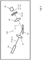
- Figure 1 shows a schematic representation of a device for Raman spectroscopy 100.
- the excitation source 10 can preferably be a narrow-band, continuously spectrally tunable and directly modulated laser diode over a wide range.
- the excitation source 10 can be a large number of excitation radiations R n with n ⁇ ⁇ with different excitation wavelengths ⁇ n from the accessible spectral range of the laser emission of the laser diode.
- Laser diodes with a laser wavelength that can be continuously tuned spectrally without mode hops are particularly preferred.
- the different excitation wavelengths ⁇ n are therefore coupled into the sample one after the other with a time differential incremental offset.
- the excitation radiation R n 'inelastically scattered by the sample 20 is then coupled into a detector 40 by a second coupling device 60 after spectral filtering by a passive filter element 30 with a filter wavelength ⁇ F that differs from the possible excitation wavelengths ⁇ n.
- the first coupling device 50 and the second coupling device 60 are preferably imaging optics, for example individual lenses, lens systems or objectives, which are used to couple radiation in and out of the sample 20.
- the passive filter element 30 can in particular be a narrow-band bandpass filter, the filter wavelength ⁇ F being determined by the central wavelength of the bandpass.
- the detector 40 can in particular be a single-channel detector.
- the excitation radiation R n ′ scattered by the sample 20 is filtered by the filter element 30 in accordance with its filter properties. After passing through the filter element 30, the detector 40 determines an intensity I n from the scattered and filtered excitation radiation R n ".
- the relationship between the individually determined intensities I n results in the time profile of the injected Excitation wavelengths ⁇ n and the filter wavelength ⁇ F of the filter element 30 a complete Raman spectrum of the sample 20, which is in particular from the determined intensities I n at the individual spectral distances between the Filter wavelength ⁇ F of the filter element 30 and the individual excitation wavelengths ⁇ n results.
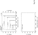
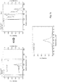
- Figures 2a to 2d show the course over time of the recording of a Raman spectrum in a device for Raman spectroscopy 100 Figure 1 .
- the reference symbols listed here apply accordingly.
- the relationships between the individual wavelengths and the associated course of the intensity values I n determined by the detector 40 assigned to the filter wavelength ⁇ F are shown.
- the relative wave number in relation to a specific reference wavelength ⁇ B which in the following is equated with the first excitation wavelength ⁇ 1 without loss of generality, is shown on the respective abscissas of the individual diagrams.
- the upper diagram therefore shows, by way of example, the typical spectral profile of a first excitation radiation R 1 of a first excitation wavelength ⁇ 1 with a relative wave number of 0 cm ⁇ 1 .
- the excitation radiation R 1 is coupled into the sample 20 and inelastically scattered by the sample.
- the Raman lines which are also only assumed as examples, are found at relative wave numbers of 300 cm -1 , 600 cm -1 and 800 cm -1 , ie at a fixed spectral distance from the excitation wavelengths ⁇ n .
- the passage area of the filter element 30 used is also shown here by way of example.
- this has a fixed spectral distance to the reference wavelength ⁇ B , ie to the first excitation wavelength ⁇ 1 , with a relative wave number of 1000 cm ⁇ 1 .
- a narrow-band bandpass is shown here as an example, which has a relative transmission of 1.0 ⁇ m the relative wave number of 1000 cm ⁇ 1 and is otherwise completely non-transparent for the incident, scattered excitation radiation R 1 '.
- the lower diagram shows the intensity values I n determined by the detector 40 for an excitation radiation R n of a certain excitation wavelength ⁇ n after spectral filtering by the filter element 30.
- the representation in this diagram is cumulative, so that all of the individual Figures 2a to 2d already determined intensity values I n of all previous excitation radiations R n are drawn in and are retained. This corresponds to a storage of the individual intensity values I n
- the Figure 2b shows the case in which a second excitation radiation R 2 of a second excitation wavelength ⁇ 2 , the second excitation wavelength ⁇ 2 differing from the first excitation wavelength ⁇ 1 and thus from the reference wavelength ⁇ B , is irradiated.
- the spectral distance between the first excitation wavelength ⁇ 1 and the second excitation wavelength ⁇ 2 is at a relative wavenumber of 100 cm ⁇ 1 .
- This shift in the excitation wavelength does not change anything in the in Figure 2a relationships shown in relation to the passage area of the filter element 30, so that a vanishing second intensity I 2 at the detector 40 is also determined in the case shown.
- the change from the first excitation radiation R 1 to the second excitation radiation R 2 can take place by means of a discrete transition.
- the excitation radiation R n can also be continuously detuned from the first excitation wavelength ⁇ 1 to the second excitation wavelength ⁇ 2.
- the excitation radiations R n that are specifically identified in the individual figures are subjected to counting in the following. The one below in Figure 2b However, it can be seen from the diagram that in the present case a large number of intensity values I l must have already been determined for different excitation radiations R l.
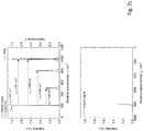
- the Figure 2c shows the case that, due to a further spectral detuning of the emission of the excitation source 10, a third excitation radiation R 3 of a third excitation wavelength ⁇ 3 , which here has a spectral distance to the first excitation wavelength ⁇ 1 , ie to the reference wavelength ⁇ B , of 200 cm -1 , is irradiated, the resulting Raman line falling precisely into the passage area of the filter element 30 with a relative wave number of 800 cm ⁇ 1.
- the detector 40 can determine a corresponding third intensity I 3 corresponding to the intensity of this Raman line. This can be added to the already saved intensity profile of all previously determined intensities.
- the individual Raman lines of a sample can be shifted spectrally one after the other over the transmission range of the filter element 30, so that with the aid of the detector 40 a Raman spectrum continuous in the accessible spectral range can be included.
- the Figure 2d shows the case that, through further spectral detuning of the emission of the excitation source 10, a fourth excitation radiation R 4 of a fourth excitation wavelength ⁇ 4 , which here has a spectral distance to the first excitation wavelength ⁇ 1 , ie to the reference wavelength ⁇ B , of 300 cm -1 , is irradiated.
- the Raman line with the relative wave number of 800 cm -1 has already been completely shifted beyond the transmission range of the filter element 30 and is now spectrally in the right-hand blocking region of the filter element 30.
- the diagram below shows the complete course of this Raman line with its exact spectral position can be taken.
- Figure 3 shows a schematic representation of the influence of the filter bandwidth.
- the diagrams shown essentially correspond to those in Figures 2a to 2d facts shown, whereby here only a single Raman line with a relative wave number of 100 cm ⁇ 1 in spectral relation to the transmission range of a broadband filter element 30 is shown.
- the Raman line of sample 20 is at the edge of the pass band, while in the lower diagram the Raman line coincides exactly with the filter wavelength ⁇ F of the pass band.
- the shape and width of the Raman lines determined by measuring different intensity values result mathematically from a convolution of the individual Raman profiles with the specific filter function of the filter element 30.
- the respective spectral profile of the excitation radiation R n used can be related to the shape and width of the contribute to certain Raman lines.
- the spectral bandwidth of the pass band of the filter element 30 is of the order of magnitude of the line width of the Raman line shown.
- the high bandwidth of the filter element 30 results in a mean value formation for the intensity values determined in each case. This averaging has a corresponding influence on the actually measured line width when determining a Raman profile. Therefore, for the most accurate measurement of a specific Raman profile of a sample 20, particularly sharp line profiles for the various excitation radiations R n and the narrowest possible filter elements with sharp band edges (laser line bandpass) are particularly preferred.
- FIG. 4 shows a schematic representation of a further device according to the invention for Raman spectroscopy 100.
- the basic structure of the device essentially corresponds to that in FIG Figure 1 illustrated embodiment, with the difference that here a filter element 30 and a further filter element 32 are present.
- a filter element 30 and a further filter element 32 are present.
- the transmitted filter wavelengths ⁇ F , ⁇ F 'of the individual filter elements 30, 32 being mutually exclusive can also distinguish each of the individual excitation wavelengths ⁇ 1 , ⁇ 2 of the respective excitation radiations R 1 , R 2 .
- a further detector 42 assigned to the further filter wavelength ⁇ F ' determines at least a first intensity I 1 ' and a second intensity I 2 ' from the excitation radiation R 1 ''', R 2 '''scattered and filtered by the sample 20 .
- the first means for coupling 50 is analogous to FIG Figure 1 a corresponding imaging optics for coupling the excitation radiation 12 onto the sample 20.
- the second means for coupling 60 comprises a non-polarizing beam splitter 60 'which couples the excitation radiation R 1 ', R 2 'scattered by the sample 20 to two detectors 40 , 42 divides.
- the second means for coupling 60 can, however, also contain further imaging optics both for coupling out the excitation radiation R 1 ′, R 2 ′ scattered by the sample 20 and for coupling into the respective detectors 40, 42.
- a coupling means is always the entirety of all the individual components present which fulfill the purpose according to the invention of coupling into the sample 20 or into the at least one detector 40. It does not depend on a coherent arrangement of the respective individual components of a means for coupling. In the present exemplary embodiment, all individual components of a means for coupling into the two detectors 40, 42, which are located between the sample 20 and the two detectors 40, 42, are thus also recorded.
- the position of the filter elements 30, 32 is not important; they can be enclosed by the respective means for coupling 60, as shown in the beam path reflected by the beam splitter.
- no limitation of the scope of the device for Raman spectroscopy 100 according to the invention can be inferred.
- the scope of the device shown can be expanded as desired.
- This exemplary embodiment also includes arrangements in which the excitation radiation R 1 ', R 2 ' scattered by the sample 20 is not split up by a beam splitter, but is achieved in any other way.
- a corresponding spatial widening of the excitation radiation R 1 ′, R 2 ′ scattered by the sample 20 is conceivable here, so that individual partial areas of the radiation can be fed to the different filter elements with their respective detectors.
- This also includes arrangements in which several different filter elements are arranged next to one another or in matrix form within a single component. This also applies accordingly to the individual detectors, which also can be in line or matrix form within a common component.
- such a multicolor filter element can also be permanently connected to a corresponding multichannel individual detector to form a common unit.
- FIG. 5 shows a schematic representation of a further device according to the invention for Raman spectroscopy 100.
- the basic structure of the device essentially corresponds to that in FIG Figure 1 illustrated embodiment, with the difference that here the filter element 30 has a filter wavelength ⁇ F and a further filter wavelength ⁇ F '.
- This is equivalent to an arrangement which consists of a filter element 30 with a filter wavelength ⁇ F and a further filter element 32 with a further filter wavelength ⁇ F ', which are arranged one behind the other, and in which the radiation incident on the detector 40 is filtered before detection takes place through both filter elements in such a way that at least one transmission region of the first filter element 30 includes the further filter wavelength ⁇ F ′ of the further filter element 32.
- the detector 40 is assigned to both the filter wavelength ⁇ F and the further filter wavelength ⁇ F 'at the same time. Conclusions about the sample 20 can be obtained from the respective ratios of the individual intensities.
- Figure 6 shows a schematic representation of a further device for Raman spectroscopy 100.
- the representation of a first means for coupling 50 was omitted here, an integration remains optional.
- the basic structure of the device shown here essentially corresponds to that in FIG Figure 1 illustrated embodiment, with the difference that two excitation sources 10 are present.
- Each of these excitation sources 10 can be designed to emit excitation radiation 12.
- it can be excitation sources 10 that can each generate and emit excitation radiation 12 of only a single excitation wavelength R 1 or R 2 , or at least one of excitation sources 10 can emit excitation radiation 12 of a plurality of excitation wavelengths.
- the number of excitation sources 10 can be expanded as desired. These can be freely combined with one another under the conditions mentioned.
- a time-shifted irradiation of individual excitation radiations R n can take place. Simultaneous irradiation of individual excitation radiations R n and a combination of these two types of irradiation are also possible.
- the individual excitation radiations R n can be coupled into the sample at a common excitation location, or for all or individual excitation radiations R n each individual stimulation sites can be provided.
- the information given on the time and location of irradiation applies, insofar as applicable, to all of the specified embodiments of the present invention.
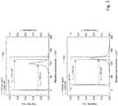
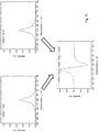
- FIGS 7a to 7c show a general scheme for Raman difference spectroscopy in a device according to the invention for Raman spectroscopy 100.
- the diagrams shown in the individual figures largely correspond to those in FIG Figures 2a to 2d shown diagrams. All information in the description apply accordingly.
- Figure 7a is analogous to the Figures 2a and 2d the time course of the recording of a Raman spectrum in a device for Raman spectroscopy 100 according to the invention Figure 1 shown.
- the lower diagram shows the spectral intensity profile of a single Raman line of a sample which has a relative wavenumber spacing of 100 cm ⁇ 1 from the excitation radiation R 1 shown.
- the excitation radiation was continuously detuned over a spectral range of this size.
- the two diagrams above show the initial and final states of such a measurement.
- the examined Raman line was spectrally shifted over the transmission range of the filter element 30.
- the relative wavenumber spacing of the filter wavelength ⁇ F to the reference wavelength ⁇ B is 150 cm -1 .
- Figure 7b is analogous to Figure 7a the result of such a measurement is shown, but the filter wavelength ⁇ F 'of the filter element 30 used has a wavenumber of 160 cm -1 relative to the reference wavelength ⁇ B.
- the transmitted filter ranges around the filter wavelengths ⁇ F , ⁇ F 'of the respective filter elements 30 partially spectrally overlap and the two filter elements 30, apart from the filter wavelengths ⁇ F , ⁇ F ', have identical transmission properties.
- the Raman spectra recorded with one of the two filters differ essentially in their spectral position in relation to the spectral distance between the reference wavelength ⁇ B and the respective filter wavelengths ⁇ F , ⁇ F '.
- the spectral position is in Figure 7b compared to the corresponding representation in Figure 7a thus shifted by a relative wave number of 10 cm -1. Further deviations between the two spectra can also result from the respective measurement background and other measurement disturbances that occur.
Claims (9)
- Procédé destiné à enregistrer un spectre raman, les étapes de procédé suivantes comprenant:- l'irradiation d'un rayonnement d'excitation (12, R1, R2) sur un échantillon (20) à analyser, l'échantillon (20) à analyser étant irradié au moins avec un premier rayonnement d'excitation (R1) d'une première longueur d'onde d'excitation (λ1) et un deuxième rayonnement d'excitation (R2) d'une deuxième longueur d'onde d'excitation (λ2), dans lequel au moins la première longueur d'onde d'excitation (λ1) est différente de la deuxième longueur d'onde d'excitation (λ2),- le filtrage sélectif en longueur d'onde du premier rayonnement d'excitation (R1') diffusé par l'échantillon (20) à l'aide d'un élément de filtrage passif (30), une longueur d'onde de filtrage transmise (λF) de l'élément de filtrage (30) étant différente au moins de la première longueur d'onde d'excitation (λ1) et de la deuxième longueur d'onde d'excitation (λ2), et dans lequel une première intensité (I1) est définie par un détecteur monocanal (40) associé à la longueur d'onde de filtrage (λF) à partir du premier rayonnement d'excitation (R1") diffusé et filtré par l'échantillon (20),- le filtrage sélectif en longueur d'onde du deuxième rayonnement d'excitation (R2') diffusé par l'échantillon (20) à l'aide de l'élément de filtrage (30), une deuxième intensité (I2) étant définie par le détecteur monocanal (40) associé à la longueur d'onde de filtrage(ÀF) à partir du deuxième rayonnement d'excitation (R2") diffusé et filtré par l'échantillon (20), au moins deux intensités définies (I1, I2) étant sauvegardées,- le filtrage sélectif en longueur d'onde au moins du premier rayonnement d'excitation (R1') diffusé par l'échantillon (20) et du deuxième rayonnement d'excitation (R2') diffusé par l'échantillon (20) à l'aide au moins d'un autre élément de filtrage passif (32), les longueurs d'onde de filtrage transmises (λF, λF') des éléments de filtrage individuels (30, 32) étant différentes les unes des autres mais également respectivement des longueurs d'onde d'excitation individuelles (λ1, λ2) des rayonnements d'excitation respectifs (R1, R2), dans lequel respectivement au moins une première intensité (I1') et une deuxième intensité (I2') sont définies à chaque fois par un autre détecteur monocanal (42) associé à l'au moins une autre longueur d'onde de filtrage (λF') à partir du rayonnement d'excitation (R1''', R2''') diffusé et filtré par l'échantillon (20), au moins deux intensités définies (I1', I2') pour l'au moins une autre longueur d'onde de filtrage (λF') étant sauvegardées, et- dans lequel des déductions sont faites sur l'échantillon (20) par une évaluation à partir des au moins quatre intensités définies (I1, I2, I1', I2') pour au moins deux longueurs d'onde de filtrage (λF, λF') et les plages de filtrage transmises se chevauchent au moins partiellement de manière spectrale autour des longueurs d'onde de filtrage (λF, λF') des éléments de filtrage respectifs (30, 32).
- Procédé selon la revendication 1, dans lequel les sources de rayonnement d'excitation (10) sont des diodes lasers à bande étroite à modulation de fréquence directe et déterminable de manière continue spectralement sur une grande plage.
- Procédé selon la revendication 1 ou 2, dans lequel les sources de rayonnement d'excitation (10) sont des diodes lasers à deux longueurs d'onde, en particulier des diodes lasers DBR à deux longueurs d'onde ramifiées en Y.
- Procédé selon une quelconque des revendications précédentes, dans lequel les éléments de filtrage passifs (30, 32) sont des filtres passe-bande à bande étroite, dans lequel une longueur d'onde de filtrage est définie par la longueur d'onde centrale d'un tel filtre passe-bande.
- Procédé selon une quelconque des revendications précédentes, dans lequel la distance spectrale entre au moins un rayonnement d'excitation (R1, R2) et un rayonnement d'excitation diffusé et filtré (R1", R1''', R2", R2''') correspond précisément à un décalage raman du rayonnement d'excitation (R1, R2) diffusé par l'échantillon (20).
- Dispositif de spectroscopie raman (100), adapté à une utilisation dans un procédé selon une quelconque des revendications précédentes, comprenant :- au moins une source d'excitation (10), conçue pour irradier un rayonnement d'excitation (12) sur un échantillon (20) à analyser et irradier l'échantillon (20) avec au moins un premier rayonnement d'excitation (R1) d'une première longueur d'onde d'excitation (λ1) et un deuxième rayonnement d'excitation (R2) d'une deuxième longueur d'onde d'excitation (λ2), dans lequel au moins la première longueur d'onde d'excitation (λ1) est différente de la deuxième longueur d'onde d'excitation (λ2),- un élément de filtrage passif (30), conçu pour filtrer de manière sélective en longueur d'onde au moins le premier rayonnement d'excitation (R1') diffusé par l'échantillon (20) et le deuxième rayonnement d'excitation (R2') diffusé par l'échantillon (20), une longueur d'onde de filtrage (λF) de l'élément de filtrage passif (30) étant différente au moins de la première longueur d'onde d'excitation (λ1) et de la deuxième longueur d'onde d'excitation (λ2),- un détecteur monocanal (40) associé à l'élément de filtrage passif (30), conçu pour définir au moins une première intensité (I1) du premier rayonnement d'excitation (R1") diffusé et filtré par l'échantillon (20) et une deuxième intensité (I2) du deuxième rayonnement d'excitation (R2") diffusé et filtré par l'échantillon (20), au moins deux intensités définies (I1, I2) étant sauvegardées,- un moyen de sauvegarde et d'évaluation des intensités définies (I1, I2),- au moins un autre élément de filtrage passif (32), les longueurs d'onde de filtrage transmises (λF, λF') des éléments de filtrage individuels (30, 32) étant différentes les unes des autres mais également respectivement des longueurs d'onde d'excitation individuelles (λ1, λ2) des rayonnements d'excitation respectifs (R1, R2) et les plages de filtrage transmises se chevauchant au moins partiellement de manière spectrale autour des longueurs d'onde de filtrage (λF, λF') des éléments de filtrage respectifs (30, 32), et- à chaque fois un autre détecteur monocanal (42) associé à l'au moins un autre élément de filtrage passif (32) et conçu pour définir à partir du rayonnement d'excitation (R1''', R2''') diffusé et filtré par l'échantillon (20) respectivement au moins une première intensité (I1') et une deuxième intensité (I2'), les au moins deux intensités (I1', I2') étant sauvegardées par le moyen de sauvegarde et d'évaluation pour l'au moins une autre longueur d'onde de filtrage (λF'),- dans lequel le moyen de sauvegarde et d'évaluation est conçu pour faire des déductions sur l'échantillon (20) à partir des au moins quatre intensités définies (I1, I2, I1', I2') pour au moins deux longueurs d'onde de filtrage (λF, λF').
- Dispositif selon la revendication 6, comprenant en outre :- un premier moyen de couplage (50), conçu pour coupler le rayonnement d'excitation (12, R1, R2) émis par la source d'excitation (10) dans l'échantillon (20) à analyser,- un second moyen de couplage (60), conçu pour coupler le rayonnement d'excitation (R1', R2') diffusé par l'échantillon (20) dans un détecteur monocanal (40), l'élément de filtrage (30) étant disposé de telle sorte que le rayonnement d'excitation (R1', R2') diffusé par l'échantillon (20) passe l'élément de filtrage (30) avant d'atteindre le détecteur monocanal (40).
- Dispositif selon la revendication 6 ou 7, dans lequel les sources d'excitation (10) sont des diodes lasers à modulation de fréquence directe et déterminable spectralement.
- Dispositif selon une des revendications 6 à 8, dans lequel les sources de rayonnement d'excitation (10) sont des diodes lasers à deux longueurs d'onde, en particulier des diodes lasers DBR à deux longueurs d'onde ramifiées en Y.
Applications Claiming Priority (2)
| Application Number | Priority Date | Filing Date | Title |
|---|---|---|---|
| DE102016111747.1A DE102016111747B4 (de) | 2016-06-27 | 2016-06-27 | Verfahren und Vorrichtung zur Raman-Spektroskopie |
| PCT/EP2017/065555 WO2018001900A1 (fr) | 2016-06-27 | 2017-06-23 | Procédé et dispositif de spectroscopie raman |
Publications (2)
| Publication Number | Publication Date |
|---|---|
| EP3465165A1 EP3465165A1 (fr) | 2019-04-10 |
| EP3465165B1 true EP3465165B1 (fr) | 2021-06-09 |
Family
ID=59101494
Family Applications (1)
| Application Number | Title | Priority Date | Filing Date |
|---|---|---|---|
| EP17732139.5A Active EP3465165B1 (fr) | 2016-06-27 | 2017-06-23 | Procédé et dispositif de spectroscopie raman |
Country Status (6)
| Country | Link |
|---|---|
| US (1) | US10794766B2 (fr) |
| EP (1) | EP3465165B1 (fr) |
| JP (1) | JP6888085B2 (fr) |
| DE (1) | DE102016111747B4 (fr) |
| DK (1) | DK3465165T3 (fr) |
| WO (1) | WO2018001900A1 (fr) |
Families Citing this family (6)
| Publication number | Priority date | Publication date | Assignee | Title |
|---|---|---|---|---|
| GB2572662B (en) * | 2018-10-05 | 2020-06-03 | Res & Innovation Uk | Raman spectrometer |
| US10760969B1 (en) | 2019-02-28 | 2020-09-01 | Biospex, Inc. | Fluorescence and systemic noise reduction in time-gated spectroscopy |
| US11326944B2 (en) * | 2019-07-12 | 2022-05-10 | Biospex, Inc. | Wearable spectrometer with filtered sensor |
| US11454540B2 (en) * | 2019-07-12 | 2022-09-27 | Biospex, Inc. | Wearable spectroscopy using filtered sensor |
| JPWO2022210192A1 (fr) * | 2021-03-31 | 2022-10-06 | ||
| DE102022124375B3 (de) * | 2022-09-22 | 2023-09-28 | Ferdinand-Braun-Institut gGmbH, Leibniz- Institut für Höchstfrequenztechnik | Vorrichtung und Verfahren zur Raman-Spektroskopie |
Family Cites Families (20)
| Publication number | Priority date | Publication date | Assignee | Title |
|---|---|---|---|---|
| CA941184A (en) * | 1970-11-05 | 1974-02-05 | Bendix Corporation (The) | Raman spectrometer utilizing a tunable laser |
| JPH0552654A (ja) * | 1991-08-23 | 1993-03-02 | Fuji Xerox Co Ltd | 励起波長掃引式ラマン分光装置 |
| US5856869A (en) * | 1995-05-01 | 1999-01-05 | Ashland Inc | Distributed bragg reflector diode laser for Raman excitation and method for use |
| US5946090A (en) * | 1996-11-19 | 1999-08-31 | The Institute Of Physical And Chemical Research | Spectrometric method and apparatus for spectrometry |
| DE10027100C2 (de) * | 2000-05-31 | 2002-08-08 | Klaus Mueller-Dethlefs | Verfahren und Vorrichtung zum Nachweisen von Substanzen in Körperflüssigkeiten |
| US7196786B2 (en) | 2003-05-06 | 2007-03-27 | Baker Hughes Incorporated | Method and apparatus for a tunable diode laser spectrometer for analysis of hydrocarbon samples |
| GB2423579B (en) * | 2003-10-17 | 2008-04-09 | Intel Corp | A method and device for detecting small numbers of molecules using surface-enhanced coherent anti-stokes raman spectroscopy |
| US7151599B2 (en) * | 2005-01-27 | 2006-12-19 | Hewlett-Packard Development Company, L.P. | Monolithic system and method for enhanced Raman spectroscopy |
| WO2007112437A2 (fr) * | 2006-03-28 | 2007-10-04 | Axsun Technologies, Inc. | Système et procédé de spectroscopie raman à laser accordable et petit nombre de pixels |
| US7696477B2 (en) * | 2007-03-14 | 2010-04-13 | Hewlett-Packard Development Company, L.P. | Electric-field-enhancement structures including dielectric particles, apparatus including same, and methods of use |
| DE102009029648B3 (de) | 2009-09-21 | 2011-03-24 | Forschungsverbund Berlin E.V. | Verfahren zur Erzeugung und zur Detektion eines Raman-Spektrums |
| DE102010015964A1 (de) * | 2010-03-15 | 2011-09-15 | Leica Microsystems Cms Gmbh | Vorrichtung und Verfahren zur multimodialen Bildgebung in der nichtlinearen Raman-Mikroskopie |
| DE202010010932U1 (de) * | 2010-04-19 | 2011-10-07 | Witec Wissenschaftliche Instrumente Und Technologie Gmbh | Vorrichtung zur Abbildung einer Probenoberfläche |
| JP5930220B2 (ja) * | 2011-03-18 | 2016-06-08 | 国立研究開発法人理化学研究所 | 非線形光学顕微鏡および非線形光学顕微鏡法 |
| US8723140B2 (en) * | 2011-08-09 | 2014-05-13 | Palo Alto Research Center Incorporated | Particle analyzer with spatial modulation and long lifetime bioprobes |
| DE102012216164B4 (de) * | 2012-09-12 | 2016-04-28 | Forschungsverbund Berlin E.V. | Vorrichtung mit einer Anordnung optischer Elemente |
| US8873041B1 (en) * | 2013-01-29 | 2014-10-28 | Bayspec, Inc. | Raman spectroscopy using multiple excitation wavelengths |
| DE112014000814T5 (de) * | 2013-02-14 | 2015-10-29 | British Columbia Cancer Agency | Verfahren und Vorrichtung für optische Messungen unter Umgebungslichtbedingungen |
| US9664561B2 (en) * | 2013-06-07 | 2017-05-30 | Board Of Regents Of The University Of Texas System | Technique to discriminate against ambient and scattered laser light in Raman spectrometry |
| DE102014018726A1 (de) * | 2014-12-16 | 2016-06-16 | Giesecke & Devrient Gmbh | Vorrichtung und Verfahren zur Prüfung von Merkmalsstoffen |
-
2016
- 2016-06-27 DE DE102016111747.1A patent/DE102016111747B4/de active Active
-
2017
- 2017-06-23 WO PCT/EP2017/065555 patent/WO2018001900A1/fr unknown
- 2017-06-23 DK DK17732139.5T patent/DK3465165T3/da active
- 2017-06-23 JP JP2019520487A patent/JP6888085B2/ja active Active
- 2017-06-23 US US16/313,668 patent/US10794766B2/en active Active
- 2017-06-23 EP EP17732139.5A patent/EP3465165B1/fr active Active
Non-Patent Citations (1)
| Title |
|---|
| None * |
Also Published As
| Publication number | Publication date |
|---|---|
| US10794766B2 (en) | 2020-10-06 |
| EP3465165A1 (fr) | 2019-04-10 |
| JP6888085B2 (ja) | 2021-06-16 |
| WO2018001900A1 (fr) | 2018-01-04 |
| DK3465165T3 (da) | 2021-08-23 |
| US20190323891A1 (en) | 2019-10-24 |
| DE102016111747B4 (de) | 2020-10-01 |
| DE102016111747A1 (de) | 2017-12-28 |
| JP2019527366A (ja) | 2019-09-26 |
Similar Documents
| Publication | Publication Date | Title |
|---|---|---|
| EP3465165B1 (fr) | Procédé et dispositif de spectroscopie raman | |
| EP1891408B1 (fr) | Procede et dispositif pour generer et detecter un spectre de raman | |
| EP3309538B1 (fr) | Système optique et procédé de spectroscopie | |
| DE102014018726A1 (de) | Vorrichtung und Verfahren zur Prüfung von Merkmalsstoffen | |
| EP2857811A1 (fr) | Spectromètre pour l'analyse de gaz | |
| EP2480868B1 (fr) | Procédé de production et de détection d'un spectre raman | |
| EP2895844B1 (fr) | Dispositif comprenant un agencement d'éléments optiques | |
| EP3839455A1 (fr) | Dispositif de détermination à haute résolution de la concentration de substances dans les milieux fluides | |
| WO2021048138A1 (fr) | Dispositif de détection et procédé pour l'analyse à distance de matériaux, et système de capteur mobile | |
| DE2948590A1 (de) | Verfahren und vorrichtung zur gasanalyse | |
| EP3792606B1 (fr) | Procédé et dispositif de spectroscopie non linéaire sur un échantillon | |
| DE102022124375B3 (de) | Vorrichtung und Verfahren zur Raman-Spektroskopie | |
| WO2018149607A1 (fr) | Microspectromètre, procédé et appareil de commande destinés au fonctionnement d'un microspectromètre | |
| DE10238356A1 (de) | Quantitative spektroskopische Bestimmung eines Absorbers | |
| EP3660474A1 (fr) | Dispositif et procédé de spectroscopie raman | |
| DE60126600T2 (de) | Analyseverfahren für stoffmischungen | |
| EP3330684B1 (fr) | Procédé pour garantir une plage de modulation | |
| DE102021108533A1 (de) | Optische Vorrichtung mit einer Triggereinheit, Triggereinheit und Verfahren zur Aufnahme von Infrarotabsorptionsspektren | |
| DE102011001695A1 (de) | Messvorrichtung und Verfahren zur Spektral auflösenden Messung elektromagnetischer Strahlung | |
| EP3575759A1 (fr) | Spectromètre et son procédé de fonctionnement | |
| WO2018077573A1 (fr) | Procédé de fonctionnement d'un microspectromètre et microspectromètre | |
| DD294784A5 (de) | Ramanspektrometer | |
| DE10134677A1 (de) | Apparatur für specktrale Messungen mittels Frequenzkämme |
Legal Events
| Date | Code | Title | Description |
|---|---|---|---|
| STAA | Information on the status of an ep patent application or granted ep patent |
Free format text: STATUS: UNKNOWN |
|
| STAA | Information on the status of an ep patent application or granted ep patent |
Free format text: STATUS: THE INTERNATIONAL PUBLICATION HAS BEEN MADE |
|
| PUAI | Public reference made under article 153(3) epc to a published international application that has entered the european phase |
Free format text: ORIGINAL CODE: 0009012 |
|
| STAA | Information on the status of an ep patent application or granted ep patent |
Free format text: STATUS: REQUEST FOR EXAMINATION WAS MADE |
|
| 17P | Request for examination filed |
Effective date: 20190103 |
|
| AK | Designated contracting states |
Kind code of ref document: A1 Designated state(s): AL AT BE BG CH CY CZ DE DK EE ES FI FR GB GR HR HU IE IS IT LI LT LU LV MC MK MT NL NO PL PT RO RS SE SI SK SM TR |
|
| AX | Request for extension of the european patent |
Extension state: BA ME |
|
| STAA | Information on the status of an ep patent application or granted ep patent |
Free format text: STATUS: EXAMINATION IS IN PROGRESS |
|
| 17Q | First examination report despatched |
Effective date: 20190816 |
|
| DAV | Request for validation of the european patent (deleted) | ||
| DAX | Request for extension of the european patent (deleted) | ||
| GRAP | Despatch of communication of intention to grant a patent |
Free format text: ORIGINAL CODE: EPIDOSNIGR1 |
|
| RIC1 | Information provided on ipc code assigned before grant |
Ipc: G01J 3/44 20060101ALI20201211BHEP Ipc: G01J 3/36 20060101ALI20201211BHEP Ipc: G01J 3/12 20060101ALI20201211BHEP Ipc: G01J 3/28 20060101ALI20201211BHEP Ipc: G01N 21/65 20060101AFI20201211BHEP |
|
| STAA | Information on the status of an ep patent application or granted ep patent |
Free format text: STATUS: GRANT OF PATENT IS INTENDED |
|
| INTG | Intention to grant announced |
Effective date: 20210121 |
|
| RAP1 | Party data changed (applicant data changed or rights of an application transferred) |
Owner name: FERDINAND-BRAUN-INSTITUT GGMBH, LEIBNITZ-INSTITUT FUER HOECHSTFREQUENZTECHNIK |
|
| GRAS | Grant fee paid |
Free format text: ORIGINAL CODE: EPIDOSNIGR3 |
|
| GRAA | (expected) grant |
Free format text: ORIGINAL CODE: 0009210 |
|
| STAA | Information on the status of an ep patent application or granted ep patent |
Free format text: STATUS: THE PATENT HAS BEEN GRANTED |
|
| RAP3 | Party data changed (applicant data changed or rights of an application transferred) |
Owner name: FERDINAND-BRAUN-INSTITUT GGMBH, LEIBNIZ-INSTITUT FUER HOECHSTFREQUENZTECHNIK |
|
| AK | Designated contracting states |
Kind code of ref document: B1 Designated state(s): AL AT BE BG CH CY CZ DE DK EE ES FI FR GB GR HR HU IE IS IT LI LT LU LV MC MK MT NL NO PL PT RO RS SE SI SK SM TR |
|
| REG | Reference to a national code |
Ref country code: GB Ref legal event code: FG4D Free format text: NOT ENGLISH |
|
| REG | Reference to a national code |
Ref country code: AT Ref legal event code: REF Ref document number: 1400921 Country of ref document: AT Kind code of ref document: T Effective date: 20210615 Ref country code: CH Ref legal event code: EP |
|
| REG | Reference to a national code |
Ref country code: DE Ref legal event code: R096 Ref document number: 502017010613 Country of ref document: DE |
|
| REG | Reference to a national code |
Ref country code: IE Ref legal event code: FG4D Free format text: LANGUAGE OF EP DOCUMENT: GERMAN |
|
| REG | Reference to a national code |
Ref country code: DK Ref legal event code: T3 Effective date: 20210818 |
|
| REG | Reference to a national code |
Ref country code: NL Ref legal event code: FP |
|
| REG | Reference to a national code |
Ref country code: LT Ref legal event code: MG9D |
|
| PG25 | Lapsed in a contracting state [announced via postgrant information from national office to epo] |
Ref country code: FI Free format text: LAPSE BECAUSE OF FAILURE TO SUBMIT A TRANSLATION OF THE DESCRIPTION OR TO PAY THE FEE WITHIN THE PRESCRIBED TIME-LIMIT Effective date: 20210609 Ref country code: LT Free format text: LAPSE BECAUSE OF FAILURE TO SUBMIT A TRANSLATION OF THE DESCRIPTION OR TO PAY THE FEE WITHIN THE PRESCRIBED TIME-LIMIT Effective date: 20210609 Ref country code: HR Free format text: LAPSE BECAUSE OF FAILURE TO SUBMIT A TRANSLATION OF THE DESCRIPTION OR TO PAY THE FEE WITHIN THE PRESCRIBED TIME-LIMIT Effective date: 20210609 Ref country code: BG Free format text: LAPSE BECAUSE OF FAILURE TO SUBMIT A TRANSLATION OF THE DESCRIPTION OR TO PAY THE FEE WITHIN THE PRESCRIBED TIME-LIMIT Effective date: 20210909 |
|
| PG25 | Lapsed in a contracting state [announced via postgrant information from national office to epo] |
Ref country code: NO Free format text: LAPSE BECAUSE OF FAILURE TO SUBMIT A TRANSLATION OF THE DESCRIPTION OR TO PAY THE FEE WITHIN THE PRESCRIBED TIME-LIMIT Effective date: 20210909 Ref country code: SE Free format text: LAPSE BECAUSE OF FAILURE TO SUBMIT A TRANSLATION OF THE DESCRIPTION OR TO PAY THE FEE WITHIN THE PRESCRIBED TIME-LIMIT Effective date: 20210609 Ref country code: RS Free format text: LAPSE BECAUSE OF FAILURE TO SUBMIT A TRANSLATION OF THE DESCRIPTION OR TO PAY THE FEE WITHIN THE PRESCRIBED TIME-LIMIT Effective date: 20210609 Ref country code: GR Free format text: LAPSE BECAUSE OF FAILURE TO SUBMIT A TRANSLATION OF THE DESCRIPTION OR TO PAY THE FEE WITHIN THE PRESCRIBED TIME-LIMIT Effective date: 20210910 Ref country code: LV Free format text: LAPSE BECAUSE OF FAILURE TO SUBMIT A TRANSLATION OF THE DESCRIPTION OR TO PAY THE FEE WITHIN THE PRESCRIBED TIME-LIMIT Effective date: 20210609 |
|
| PG25 | Lapsed in a contracting state [announced via postgrant information from national office to epo] |
Ref country code: SM Free format text: LAPSE BECAUSE OF FAILURE TO SUBMIT A TRANSLATION OF THE DESCRIPTION OR TO PAY THE FEE WITHIN THE PRESCRIBED TIME-LIMIT Effective date: 20210609 Ref country code: SK Free format text: LAPSE BECAUSE OF FAILURE TO SUBMIT A TRANSLATION OF THE DESCRIPTION OR TO PAY THE FEE WITHIN THE PRESCRIBED TIME-LIMIT Effective date: 20210609 Ref country code: ES Free format text: LAPSE BECAUSE OF FAILURE TO SUBMIT A TRANSLATION OF THE DESCRIPTION OR TO PAY THE FEE WITHIN THE PRESCRIBED TIME-LIMIT Effective date: 20210609 Ref country code: PT Free format text: LAPSE BECAUSE OF FAILURE TO SUBMIT A TRANSLATION OF THE DESCRIPTION OR TO PAY THE FEE WITHIN THE PRESCRIBED TIME-LIMIT Effective date: 20211011 Ref country code: RO Free format text: LAPSE BECAUSE OF FAILURE TO SUBMIT A TRANSLATION OF THE DESCRIPTION OR TO PAY THE FEE WITHIN THE PRESCRIBED TIME-LIMIT Effective date: 20210609 Ref country code: CZ Free format text: LAPSE BECAUSE OF FAILURE TO SUBMIT A TRANSLATION OF THE DESCRIPTION OR TO PAY THE FEE WITHIN THE PRESCRIBED TIME-LIMIT Effective date: 20210609 Ref country code: EE Free format text: LAPSE BECAUSE OF FAILURE TO SUBMIT A TRANSLATION OF THE DESCRIPTION OR TO PAY THE FEE WITHIN THE PRESCRIBED TIME-LIMIT Effective date: 20210609 |
|
| REG | Reference to a national code |
Ref country code: CH Ref legal event code: PL |
|
| PG25 | Lapsed in a contracting state [announced via postgrant information from national office to epo] |
Ref country code: PL Free format text: LAPSE BECAUSE OF FAILURE TO SUBMIT A TRANSLATION OF THE DESCRIPTION OR TO PAY THE FEE WITHIN THE PRESCRIBED TIME-LIMIT Effective date: 20210609 |
|
| REG | Reference to a national code |
Ref country code: BE Ref legal event code: MM Effective date: 20210630 |
|
| REG | Reference to a national code |
Ref country code: DE Ref legal event code: R097 Ref document number: 502017010613 Country of ref document: DE |
|
| PG25 | Lapsed in a contracting state [announced via postgrant information from national office to epo] |
Ref country code: MC Free format text: LAPSE BECAUSE OF FAILURE TO SUBMIT A TRANSLATION OF THE DESCRIPTION OR TO PAY THE FEE WITHIN THE PRESCRIBED TIME-LIMIT Effective date: 20210609 Ref country code: LU Free format text: LAPSE BECAUSE OF NON-PAYMENT OF DUE FEES Effective date: 20210623 |
|
| PLBE | No opposition filed within time limit |
Free format text: ORIGINAL CODE: 0009261 |
|
| STAA | Information on the status of an ep patent application or granted ep patent |
Free format text: STATUS: NO OPPOSITION FILED WITHIN TIME LIMIT |
|
| PG25 | Lapsed in a contracting state [announced via postgrant information from national office to epo] |
Ref country code: LI Free format text: LAPSE BECAUSE OF NON-PAYMENT OF DUE FEES Effective date: 20210630 Ref country code: CH Free format text: LAPSE BECAUSE OF NON-PAYMENT OF DUE FEES Effective date: 20210630 |
|
| 26N | No opposition filed |
Effective date: 20220310 |
|
| PG25 | Lapsed in a contracting state [announced via postgrant information from national office to epo] |
Ref country code: AL Free format text: LAPSE BECAUSE OF FAILURE TO SUBMIT A TRANSLATION OF THE DESCRIPTION OR TO PAY THE FEE WITHIN THE PRESCRIBED TIME-LIMIT Effective date: 20210609 |
|
| PG25 | Lapsed in a contracting state [announced via postgrant information from national office to epo] |
Ref country code: BE Free format text: LAPSE BECAUSE OF NON-PAYMENT OF DUE FEES Effective date: 20210630 |
|
| PG25 | Lapsed in a contracting state [announced via postgrant information from national office to epo] |
Ref country code: CY Free format text: LAPSE BECAUSE OF FAILURE TO SUBMIT A TRANSLATION OF THE DESCRIPTION OR TO PAY THE FEE WITHIN THE PRESCRIBED TIME-LIMIT Effective date: 20210609 |
|
| PG25 | Lapsed in a contracting state [announced via postgrant information from national office to epo] |
Ref country code: HU Free format text: LAPSE BECAUSE OF FAILURE TO SUBMIT A TRANSLATION OF THE DESCRIPTION OR TO PAY THE FEE WITHIN THE PRESCRIBED TIME-LIMIT; INVALID AB INITIO Effective date: 20170623 |
|
| PGFP | Annual fee paid to national office [announced via postgrant information from national office to epo] |
Ref country code: NL Payment date: 20230620 Year of fee payment: 7 Ref country code: IE Payment date: 20230620 Year of fee payment: 7 Ref country code: FR Payment date: 20230620 Year of fee payment: 7 Ref country code: DK Payment date: 20230621 Year of fee payment: 7 Ref country code: DE Payment date: 20230608 Year of fee payment: 7 |
|
| PGFP | Annual fee paid to national office [announced via postgrant information from national office to epo] |
Ref country code: AT Payment date: 20230616 Year of fee payment: 7 |
|
| PGFP | Annual fee paid to national office [announced via postgrant information from national office to epo] |
Ref country code: IT Payment date: 20230630 Year of fee payment: 7 Ref country code: GB Payment date: 20230622 Year of fee payment: 7 |
|
| PG25 | Lapsed in a contracting state [announced via postgrant information from national office to epo] |
Ref country code: MK Free format text: LAPSE BECAUSE OF FAILURE TO SUBMIT A TRANSLATION OF THE DESCRIPTION OR TO PAY THE FEE WITHIN THE PRESCRIBED TIME-LIMIT Effective date: 20210609 |