EP2857811A1 - Spectromètre pour l'analyse de gaz - Google Patents
Spectromètre pour l'analyse de gaz Download PDFInfo
- Publication number
- EP2857811A1 EP2857811A1 EP13187159.2A EP13187159A EP2857811A1 EP 2857811 A1 EP2857811 A1 EP 2857811A1 EP 13187159 A EP13187159 A EP 13187159A EP 2857811 A1 EP2857811 A1 EP 2857811A1
- Authority
- EP
- European Patent Office
- Prior art keywords
- fabry
- filter
- pérot
- light
- spectrometer
- Prior art date
- Legal status (The legal status is an assumption and is not a legal conclusion. Google has not performed a legal analysis and makes no representation as to the accuracy of the status listed.)
- Granted
Links
- 238000004868 gas analysis Methods 0.000 title claims abstract description 7
- 238000000411 transmission spectrum Methods 0.000 claims abstract description 35
- 230000003287 optical effect Effects 0.000 claims abstract description 19
- 238000010521 absorption reaction Methods 0.000 claims abstract description 17
- 230000003595 spectral effect Effects 0.000 claims description 31
- 238000000034 method Methods 0.000 claims description 17
- 238000005070 sampling Methods 0.000 claims description 16
- 230000008859 change Effects 0.000 claims description 8
- 239000007789 gas Substances 0.000 description 41
- 230000005540 biological transmission Effects 0.000 description 38
- 238000001228 spectrum Methods 0.000 description 10
- 238000005259 measurement Methods 0.000 description 8
- 238000011156 evaluation Methods 0.000 description 5
- 239000000203 mixture Substances 0.000 description 4
- 238000004611 spectroscopical analysis Methods 0.000 description 4
- 238000000862 absorption spectrum Methods 0.000 description 3
- 238000010438 heat treatment Methods 0.000 description 3
- 230000008569 process Effects 0.000 description 3
- 241000251730 Chondrichthyes Species 0.000 description 2
- 238000005033 Fourier transform infrared spectroscopy Methods 0.000 description 2
- 238000001514 detection method Methods 0.000 description 2
- 230000009977 dual effect Effects 0.000 description 2
- 238000001745 non-dispersive infrared spectroscopy Methods 0.000 description 2
- 230000035484 reaction time Effects 0.000 description 2
- 238000004566 IR spectroscopy Methods 0.000 description 1
- 238000012512 characterization method Methods 0.000 description 1
- 238000006243 chemical reaction Methods 0.000 description 1
- 125000004122 cyclic group Chemical group 0.000 description 1
- 230000001419 dependent effect Effects 0.000 description 1
- 230000001066 destructive effect Effects 0.000 description 1
- 230000000694 effects Effects 0.000 description 1
- 238000009615 fourier-transform spectroscopy Methods 0.000 description 1
- 229930195733 hydrocarbon Natural products 0.000 description 1
- 150000002430 hydrocarbons Chemical class 0.000 description 1
- 230000003993 interaction Effects 0.000 description 1
- 238000005305 interferometry Methods 0.000 description 1
- 238000012423 maintenance Methods 0.000 description 1
- 239000012528 membrane Substances 0.000 description 1
- 230000010355 oscillation Effects 0.000 description 1
- 230000005855 radiation Effects 0.000 description 1
- 238000007493 shaping process Methods 0.000 description 1
- 229910052710 silicon Inorganic materials 0.000 description 1
- 239000010703 silicon Substances 0.000 description 1
- 238000012360 testing method Methods 0.000 description 1
- 230000009466 transformation Effects 0.000 description 1
Images


Classifications
-
- G—PHYSICS
- G01—MEASURING; TESTING
- G01J—MEASUREMENT OF INTENSITY, VELOCITY, SPECTRAL CONTENT, POLARISATION, PHASE OR PULSE CHARACTERISTICS OF INFRARED, VISIBLE OR ULTRAVIOLET LIGHT; COLORIMETRY; RADIATION PYROMETRY
- G01J3/00—Spectrometry; Spectrophotometry; Monochromators; Measuring colours
- G01J3/02—Details
- G01J3/0205—Optical elements not provided otherwise, e.g. optical manifolds, diffusers, windows
- G01J3/0235—Optical elements not provided otherwise, e.g. optical manifolds, diffusers, windows using means for replacing an element by another, for replacing a filter or a grating
-
- G—PHYSICS
- G01—MEASURING; TESTING
- G01J—MEASUREMENT OF INTENSITY, VELOCITY, SPECTRAL CONTENT, POLARISATION, PHASE OR PULSE CHARACTERISTICS OF INFRARED, VISIBLE OR ULTRAVIOLET LIGHT; COLORIMETRY; RADIATION PYROMETRY
- G01J3/00—Spectrometry; Spectrophotometry; Monochromators; Measuring colours
- G01J3/12—Generating the spectrum; Monochromators
- G01J3/26—Generating the spectrum; Monochromators using multiple reflection, e.g. Fabry-Perot interferometer, variable interference filters
-
- G—PHYSICS
- G01—MEASURING; TESTING
- G01J—MEASUREMENT OF INTENSITY, VELOCITY, SPECTRAL CONTENT, POLARISATION, PHASE OR PULSE CHARACTERISTICS OF INFRARED, VISIBLE OR ULTRAVIOLET LIGHT; COLORIMETRY; RADIATION PYROMETRY
- G01J3/00—Spectrometry; Spectrophotometry; Monochromators; Measuring colours
- G01J3/28—Investigating the spectrum
- G01J3/42—Absorption spectrometry; Double beam spectrometry; Flicker spectrometry; Reflection spectrometry
- G01J3/433—Modulation spectrometry; Derivative spectrometry
-
- G—PHYSICS
- G01—MEASURING; TESTING
- G01N—INVESTIGATING OR ANALYSING MATERIALS BY DETERMINING THEIR CHEMICAL OR PHYSICAL PROPERTIES
- G01N21/00—Investigating or analysing materials by the use of optical means, i.e. using sub-millimetre waves, infrared, visible or ultraviolet light
- G01N21/17—Systems in which incident light is modified in accordance with the properties of the material investigated
- G01N21/25—Colour; Spectral properties, i.e. comparison of effect of material on the light at two or more different wavelengths or wavelength bands
- G01N21/31—Investigating relative effect of material at wavelengths characteristic of specific elements or molecules, e.g. atomic absorption spectrometry
- G01N21/35—Investigating relative effect of material at wavelengths characteristic of specific elements or molecules, e.g. atomic absorption spectrometry using infrared light
- G01N21/3504—Investigating relative effect of material at wavelengths characteristic of specific elements or molecules, e.g. atomic absorption spectrometry using infrared light for analysing gases, e.g. multi-gas analysis
-
- G—PHYSICS
- G01—MEASURING; TESTING
- G01N—INVESTIGATING OR ANALYSING MATERIALS BY DETERMINING THEIR CHEMICAL OR PHYSICAL PROPERTIES
- G01N33/00—Investigating or analysing materials by specific methods not covered by groups G01N1/00 - G01N31/00
- G01N33/0004—Gaseous mixtures, e.g. polluted air
- G01N33/0009—General constructional details of gas analysers, e.g. portable test equipment
- G01N33/0062—General constructional details of gas analysers, e.g. portable test equipment concerning the measuring method, e.g. intermittent, or the display, e.g. digital
-
- G—PHYSICS
- G01—MEASURING; TESTING
- G01J—MEASUREMENT OF INTENSITY, VELOCITY, SPECTRAL CONTENT, POLARISATION, PHASE OR PULSE CHARACTERISTICS OF INFRARED, VISIBLE OR ULTRAVIOLET LIGHT; COLORIMETRY; RADIATION PYROMETRY
- G01J3/00—Spectrometry; Spectrophotometry; Monochromators; Measuring colours
- G01J3/12—Generating the spectrum; Monochromators
- G01J2003/1282—Spectrum tailoring
Definitions
- the invention relates to a spectrometer and a method for spectrometric gas analysis according to the preamble of claim 1 and 15, respectively.
- infrared spectroscopy for measuring the concentration of individual components of a gas mixture. They are all based on the basic principle of radiating infrared test light in a measuring cell with the gas to be examined. Each gas shows a characteristic absorption at frequencies corresponding to the spectral lines of its molecules. This absorption changes the properties of the incident light, which can be detected and evaluated in various ways.
- FTIR Fourier transform spectroscopy
- NDIR non-dispersive infrared spectroscopy
- an optical bandpass filter is arranged in front of the detector, which selectively transmits light corresponding to a spectral line to be examined. This relatively simple method is therefore inflexible, since an optical bandpass filter must be provided for each gas component to be detected.
- the transmitted light is thus pulsed at a known modulation frequency, and the receiver selects by analog mixing or digital evaluation, the measurement signal based on the modulation frequency to suppress interferers in other frequency ranges.
- the modulation of the transmitted light is conventionally pulsed Light sources or their downstream mechanical pulse shaper ("chopper") generated. Both are unsatisfactory because pulsed infrared emitters allow only low modulation frequencies and a mechanical pulse shaper is vulnerable and inflexible, must be stabilized and requires a lot of space.
- a Fabry-Pérot filter is an optical resonator formed of two partially transparent mirrors. By constructive and destructive interference only wavelengths are transmitted which correspond to the resonance conditions. Accordingly, a first transmission maximum at the resonance frequency and further transmission maxima of a higher order occur at the harmonics, while the intermediate frequencies are almost extinguished. The distance between the transmission maxima is called free spectral range.
- the transmission maxima are simultaneously influenced in terms of their width and their mutual distance.
- a fine needle of a transmission maximum therefore requires a small free spectral range, while, conversely, a large free spectral range can only be achieved at the price of transmission maxima of a large half-width.
- This characterization of Fabry-Pérot filters is also detected in the so-called finesse, which is defined as the ratio of the free spectral range to the half-width.
- the passband of a Fabry-Pérot filter usually has a multiplicity of absorption lines of one or more gas components, either because they are within the same transmission maximum of a Fabry-Pèrot filter with a high half-width or because the free spectral range of a Fabry-Perot Filter is low enough to selectively adjust the Fabry-Pérot filter to an absorption line without having secondary maxima matching other absorption lines.
- spectral resolution achievable with a Fabry-Pérot filter is therefore limited. If one wants to achieve a higher spectral resolution, then conventionally resorting to the above-mentioned methods such as FTIR or grating spectroscopy.
- a spectrometer and a method for spectrometric gas analysis according to claim 1 or 15.
- light is imparted with the aid of a filter arrangement frequency characteristics before it is blasted for spectrometry in a measuring cell with the gas or gas mixture to be examined.
- the absorption by the gas is then detected, thus measuring the concentration of gas components.
- the invention is based on the basic idea of providing a plurality of Fabry-Pérot filters in the filter arrangement. By adjusting at least one of these Fabry-Pérot filters, the transmission spectrum of the filter arrangement changes and so desired frequency characteristics of the light can be achieved. This makes it possible, for example, to adjust the spectrometer in succession to the absorption spectra of different gases of a gas mixture or to continuously tune the filter arrangement in order to scan a larger wavelength range.
- the invention shows the advantages of Fabry-Pérot filters, which are inexpensive, compact, mechanically simple and thus low maintenance and robust and have a high optical throughput. Variable frequency characteristics of the incident light can be adjusted very quickly and flexibly.
- the multiple arrangement of Fabry-Pérot filters enables a high spectral resolution. Namely, there are new degrees of freedom of the adjustment, which can be used, for example, to achieve both a low half-width and a large free spectral range. This would be inconceivable for a simple Fabry-Pérot filter because of the direct relationship between these quantities and limits the conventionally achievable spectral resolution significantly.
- the Fabry-Pérot filters are electrostatic or piezoelectrically controlled microsystems (MEMS, Micro Electro Mechanical System). This combines robustness, small sizes and short reaction times at least in the millisecond range.
- MEMS Micro Electro Mechanical System
- the filter arrangement preferably has three Fabry-Pérot filters. In principle, even two Farby-Pérot filters provide greater flexibility. The more Fabry-Pérot filters are additionally provided in the filter assembly, the more degrees of freedom are gained. A number of three Farby-Pérot filters are a preferred compromise.
- an assignment of mirror intervals of the Fabry-Pérot filter and associated transmission spectrum is preferably stored. This assignment is specified at the factory or initially learned in calibration measurements. Based on the assignment, the control unit can set a desired transmission spectrum of the filter arrangement. An adjustment process involves at least one Fabry-Pérot filter, but it can also be several or all.
- the Fabry-Pérot filters preferably have staggered half-widths, in particular, in each case a Fabry-Pérot filter with low, medium and high half-width is provided in three Fabry-Pérot filters. Intuitively most comprehensible is an interplay of the Fabry-Pérot filters, in which the Fabry-Pérot filter of lowest half-width determines the spectral resolution and the other Fabry-Pérot filters staggered to ensure that the higher orders of the finer-resolution Fabry-Pérot Filters are hidden.
- there are other combinations to achieve a desired transmission spectrum in many situations, there are other combinations to achieve a desired transmission spectrum.
- the transmission spectrum preferably has a narrowband maximum at a predeterminable frequency.
- more preferably frequency components outside this maximum are largely suppressed.
- the filter arrangement ensures that only light with a certain frequency gets into the measuring cell. With several individual measurements with intermediate shifting of the frequency of the maximum so a spectrum can be sampled.
- the control unit is preferably designed to cyclically vary the transmission spectrum of the filter arrangement such that the amplitude of the maximum is modulated.
- the filter arrangement also forms an optical pulse shaper.
- This is achieved in particular by a coordinated cyclical adjustment Fabry-Pérot filters.
- the maximum of the Fabry-Pérot filter with the largest half width is cyclically shifted so that the position of this maximum coincides to different degrees with the maxima of the other Fabry-Pérot filters. This achieves a similar effect as through an aperture that alternatively transmits or blocks the light.
- the amplitude is preferably modulated with a predefinable function, in particular a delta pulse, a sine or an exponentially increasing and then abruptly falling pulse.
- a delta pulse corresponds to a pure light-dark modulation.
- a sine or cosine supports electronic and digital lock-in methods particularly well.
- the function can be selected almost arbitrarily by moving the filter arrangement in intermediate positions, which lead to different attenuation of the transmission maximum.
- modulation with pulses that look similar to shark fins i. initially grow comparatively slowly exponentially to its maximum brightness and then suddenly fall back into the dark state. Such modulation is an easy-to-calculate example.
- the control unit is preferably designed to change the transmission spectrum according to a sampling scheme, according to which a respective transmission spectrum is generated with a maximum at a sampling frequency, the amplitude of the maximum at the sampling frequency is modulated over several cycles and the sampling frequency is then systematically changed.
- a sampling scheme the spectrum is sequentially scanned at different frequencies each with a pulse train.
- a signal of the detector is preferably evaluated with a lock-in method based on the known modulation.
- This is the principle of the lock-in amplifier, which adjusts itself analog or digital to the known modulation frequency, thereby achieving a much better signal-to-noise ratio.
- the required modulation of the light is preferably carried out in the filter arrangement as just described itself, but in principle also an additional optical pulse shaper or a pulsed light source is conceivable.
- an additional optical bandpass filter is preferably provided in order to block out higher order maxima of at least one of the Fabry-Pérot filters, preferably the Fabry-Pérot filter of the highest free spectral range.
- the Fabry-Pérot filters with larger free spectral range practically fulfill this function by suppressing higher orders of Fabry-Pérot filters of a smaller free spectral range.
- the optical bandpass filter limits the frequency band as a whole to a region of interest that is preferably at most as large as the resulting free spectral region of the filter array.
- Such a bandpass filter can also be integrated into a transmitting or receiving optics in the light path.
- the light source or detector is narrowband enough to exclude any remaining higher orders of the filter arrangement.
- the measuring cell is preferably a photoacoustic measuring cell. In it also low gas concentrations can be measured with short absorption distances, and the measuring cell has a high dynamic range.
- the photoacoustic measuring cell measures pressure changes which are produced by heating the gas upon radiation absorption of the light irradiated into the measuring cell. These pressure changes are measured acoustically, for example with a microphone or pressure sensor. In this case, modulated light preferably ensures sufficient state changes.
- this has a vibrating beam (cantilever) approximately in the form of a silicon membrane and an interferometer for optically measuring the deflection of the vibrating beam by means of interferometry.
- the absorption ensures with sufficient agreement of the frequency characteristics of the incident light and the absorption spectrum of a gas component for a very rapid heating and thus a pulse-like pressure change of the gas.
- the resulting deflection of the vibrating beam is then evaluated interferometrically.
- a calibration unit is provided, which is insertable into and removable from the light path and the an interference filter with a known reference frequency or a gas cuvette having a reference gas.
- a known reference frequency or a gas cuvette having a reference gas is provided.
- the calibration unit preferably has a traversing carriage or a filter wheel. This allows calibration to be easily performed and repeated if necessary. In each case a plurality of reference gases or interference filters may be provided in order to calibrate a plurality of calibration points.
- At least one Fabry-Pérot filter is preferably removable from the light path and re-mounted in the light path. This can also serve a carriage.
- the Fabry-Pérot filters can be calibrated in this way not only together as a filter arrangement, but individually or in groups. This simplifies the calibration process and leads to more accurate results.
- FIG. 1 shows an overview of a spectrometer 10 for determining the concentration of gas components by means of absorption measurement.
- a light source 12 emits light 14, which passes on its optical path 16 a first optical system 18, a bandpass filter 20, a filter arrangement 22 with a plurality of Fabry-Pérot filters 24a-c and a second optical system 26 and is then irradiated into a measuring cell 28.
- the measuring cell 28 is the gas to be examined 30 or a gas mixture, for symbolized by arrows, a gas inlet 32 and a gas outlet 34 are provided.
- a detector which is designed here as a vibrating beam 36 with a (laser) interferometer 38 for determining the deflection of the vibrating beam 36.
- a control and evaluation unit 40 has a measuring unit 42 for evaluating the signals of the interferometer 38, a control unit 44 for adjusting the filter arrangement 22 and the remaining necessary control and evaluation functionality.
- the division of the control and evaluation unit 40 is only the illustrative Explanation, it is also possible any other distribution to one or more physical control and evaluation units, which exchange data and state parameters with each other.
- the light source 12 is preferably a broadband infrared radiator. This covers the typical frequency range of spectral lines of the molecules to be examined gases.
- the light 12 is focused by the first optics 18, wherein the lens shown is only representative of one or more suitable optical elements for beam shaping and beam guidance.
- the bandpass filter 20 cuts out of the wide frequency band of the light source 12 a coarse area within which absorption bands of the gases to be examined are located. For example, in the frequency band of 4.3 microns to 7.4 microns, the gas components CO, NO, SO 2 , NO 2 , N 2 O, CO 2 and H 2 O are measured and in the frequency band of 3 microns to 3.8 ⁇ m numerous hydrocarbons.
- the bandpass filter 20 may also be located at a different position in the light path 16 than shown or integrated into one of the optics 18, 26. Alternatively, a slightly narrower light source 12 is used, such as an LED, and the bandpass filter 20 is omitted.
- the filter arrangement 22 itself can also assume the function of the bandpass filter 20, at least within limits.
- the transmission spectrum of the filter assembly 22 may be predetermined by adjusting the Fabry-Pérot filters 24a-c, discussed in more detail below, such that the light 14 has certain frequency characteristics after passing through the filter assembly 22.
- the transmission maximum is deliberately matched with a known spectral line to measure the associated gas component.
- the second optics 26 conducts the filtered light 14 into the measuring cell 28, whereby, as in the case of the first optic 18, the representation as a simple lens is to be understood purely by way of example.
- further optical elements may be provided in particular between the Fabry-Pérot filters 24a-c.
- the control unit 44 is able to change parameters of at least one of the Fabry-Pérot filters 24a-c, in particular the air gap between the two semitransparent mirrors and thus the resonance frequency.
- This can be implemented, for example, by electrostatic or piezoelectric actuation of MEMS-designed Fabry-Pérot filters with short reaction times without macroscopic movements.
- the transmission spectrum of the filter arrangement 22 can be predetermined.
- FIG. 2a shows an example of three transmission spectra of three Fabry-Pérot filters 24a-c.
- a Fabry-Pérot filter 24a of the smallest half width produces the thin-line, closely spaced needle-like transmission peaks.
- Another Fabry-Pérot filter 22b of medium half width has three transmission maxima shown in bold line in the frequency section shown.
- a third Fabry-Perot filter 24c has in the illustrated frequency section only a relatively broad dotted line transmission maximum. This is also illustrated by the initially described dependence on half-width and density of the transmission maxima, ie free spectral range: the narrower and thus more suitable for higher spectral resolution a transmission maximum, the closer the next transmission maximum of higher order. None of the Fabry-Pérot filters 24a-c individually is therefore suitable for high-resolution spectrometry because the light is not limited to a specific narrow frequency range.
- FIG. 2b shows the associated common transmission spectrum, ie ultimately the pointwise multiplication of the three transmission spectra FIG. 2a , This results in a clearly pronounced transmission maximum at the point where in FIG. 2a Superimpose transmission maxima of all three Fabry-Pérot filters 24a-c. The remaining transmission maxima are still recognizable, but very clearly suppressed, because in each case a Fabry-Pérot filter 24a-c with a larger free spectral range suppresses the transmission maxima of a higher order of a Fabry-Pérot filter with a narrow half width. The logarithmic representation of the FIG. 2b to be observed.
- the free spectral range is not necessarily sufficient to cover the entire bandwidth of the light source 12, for which optionally the bandpass filter 20 additionally reduces the frequency range, for example to the detail shown in the figures or generally a passband that is at most as large as the free spectral range of one or more of the Fabry-Pérot filters 24a-c.
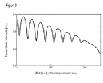
- FIG. 3 shows by way of example the result of the successive scanning of the spectrum of CO.
- This high-resolution spectrometry can now be extended with the same structure by a modulation in order to enable in the detection of a lock-in process.
- the oscillating beam 24 is thereby periodically deflected and its oscillation evaluated interferometrically.
- lock-in methods can also be used otherwise, for example to amplify the signal of an infrared detector.
- the filter assembly 22 is in a dual function itself and thus without additional component in a position to produce the required modulation.
- the Fabry-Pérot filter 24a-c periodically detuned against each other and thus specifically in FIG. 2b temporarily leave the light state shown.
- figure 4a shows a similar representation as FIG. 2a , but here the transmission maxima are shifted from each other, so that they overlap as possible at no frequency. This is immediately recognizable for the widest transmission maximum shown in dotted line.
- the average transmission maximum shown in bold line also no longer agrees at 4.6 ⁇ m with a needle-like transmission maximum shown in a thin line.
- FIG. 5 explains the procedure.
- the presentation of the FIG. 5a essentially corresponds to the FIG. 2a but an arrow 46 indicates a modulation scheme. This is to adjust the air gap of the Fabry-Pérot filter 24c with the largest half-width and the largest free spectral range. This is only a particularly intuitively understandable example; other combinations of settings of the Fabry-Pérot filters 24a-c would lead to the desired result.
- FIG. 6 shows a section of an exemplary sampling of a CO absorption line with a sampling and modulation scheme. At each set pass wavelength, five light-dark cycles are performed. Each ten data points thus correspond to a transmission wavelength. The cycles at four transmission wavelengths are illustrated by arrows 48.
- FIG. 7 shows an excerpt of another exemplary sampling of a CO line with a different sampling and modulation scheme.
- two modulation cycles are performed at each set pass wavelength, as illustrated by arrows 50 for four cycles.
- the modulation itself is no longer a simple Patoscuro change, but leads over several steps, here a total of ten intensity modulations, with an exponential growth and subsequent abrupt decay ("shark fin").
- shank fin a simple Canal of ⁇
- the filter assembly 22 is thus able to transmit light in a narrow wavelength range about a successively changing central wavelength in the measuring cell 28, wherein the light can also be modulated if necessary.
- the transmission spectrum of a Fabry-Pérot filter 24a-c depends on control parameters that can be set by the control unit 44.
- additional elements 52 are introduced as a calibration unit in the light path 16 or removed therefrom.
- the elements 52 have a known spectrum, which is used as a reference.
- Two examples of such elements 52 are interference filters of known wavelength-dependent transmission or closed reference gas cuvettes of known length and filling with one or more gas components of known concentration. It should be paid attention to temperature and in the case of a reference gas also pressure stability.
- the transmission spectra including transmission wavelength and transmission intensity of the Fabry-Pérot filters 24a-c are calibrated depending on one or more control parameters.
- the introduction or removal of the elements 52 can be achieved by a filter wheel or by mechanical transport carriages.
- An alternative embodiment provides, instead of elements 52 in the light path 16, a narrow band laser light source for calibration.
- FIG. 9 shows another embodiment of the spectrometer 10.
- the Fabry-Pérot filters 24a-c are also removably and disposable from the light path 16 via trays or the like, singly or in groups. This can also be done with the embodiment according to FIG. 8 combine.
- the embodiment according to FIG. 9 allows the Fabry-Pérot filters 24a-c individually or in groups and not just the filter assembly 22 in its entirety. This increases the accuracy and facilitates the procedure.
- the measuring cell 28 For calibrating the Fabry-Pérot filters 24a-c, it is also conceivable to fill the measuring cell 28 with a calibration or reference gas whose gas components, including their concentration, are known. It is also possible, instead of the measuring cell 28, to introduce a detector into the light path 16 for calibration, which measure the intensity in the relevant spectral range and can thus check the setting of the filter arrangement 22 or the properties of the entire light path 16.
Priority Applications (4)
| Application Number | Priority Date | Filing Date | Title |
|---|---|---|---|
| EP13187159.2A EP2857811B1 (fr) | 2013-10-02 | 2013-10-02 | Spectromètre pour l'analyse de gaz |
| US14/488,608 US9752931B2 (en) | 2013-10-02 | 2014-09-17 | Spectrometer with multiple Fabry-Perot filters for gas analysis |
| CN201410521849.3A CN104515745B (zh) | 2013-10-02 | 2014-09-30 | 用于气体分析的光谱仪 |
| KR1020140133363A KR101621903B1 (ko) | 2013-10-02 | 2014-10-02 | 가스 분석용 분광기 |
Applications Claiming Priority (1)
| Application Number | Priority Date | Filing Date | Title |
|---|---|---|---|
| EP13187159.2A EP2857811B1 (fr) | 2013-10-02 | 2013-10-02 | Spectromètre pour l'analyse de gaz |
Publications (2)
| Publication Number | Publication Date |
|---|---|
| EP2857811A1 true EP2857811A1 (fr) | 2015-04-08 |
| EP2857811B1 EP2857811B1 (fr) | 2015-09-23 |
Family
ID=49263241
Family Applications (1)
| Application Number | Title | Priority Date | Filing Date |
|---|---|---|---|
| EP13187159.2A Active EP2857811B1 (fr) | 2013-10-02 | 2013-10-02 | Spectromètre pour l'analyse de gaz |
Country Status (4)
| Country | Link |
|---|---|
| US (1) | US9752931B2 (fr) |
| EP (1) | EP2857811B1 (fr) |
| KR (1) | KR101621903B1 (fr) |
| CN (1) | CN104515745B (fr) |
Cited By (1)
| Publication number | Priority date | Publication date | Assignee | Title |
|---|---|---|---|---|
| US11460407B2 (en) | 2017-08-04 | 2022-10-04 | Carl Zeiss Jena Gmbh | Sample-based gas quality control by means of raman spectroscopy |
Families Citing this family (13)
| Publication number | Priority date | Publication date | Assignee | Title |
|---|---|---|---|---|
| JP5987573B2 (ja) | 2012-09-12 | 2016-09-07 | セイコーエプソン株式会社 | 光学モジュール、電子機器、及び駆動方法 |
| EP2770319B2 (fr) * | 2013-02-25 | 2022-01-26 | Sick Ag | Appareil de mesure de gaz |
| DE102014226845B4 (de) * | 2014-12-17 | 2016-11-03 | Siemens Aktiengesellschaft | Absorptionsspektrometer |
| CN106361269A (zh) * | 2015-07-23 | 2017-02-01 | 松下知识产权经营株式会社 | 光检测装置以及光检测方法 |
| DE102015012429B4 (de) * | 2015-09-25 | 2019-09-05 | Drägerwerk AG & Co. KGaA | Verfahren zur Signalerfassung in einem Gasanalysesystem |
| CN109477789B (zh) * | 2016-07-21 | 2021-10-22 | 西门子医疗保健诊断公司 | 使用比色皿之间的参考测量来消除源灯强度漂移效应 |
| CN106568507B (zh) * | 2016-11-07 | 2018-04-06 | 西北核技术研究所 | 基于特征吸收谱线测量f‑p腔自由光谱范围的方法及装置 |
| EP3508836B1 (fr) | 2018-01-05 | 2020-07-29 | Infineon Technologies AG | Système et procédé photoacoustique permettant d'estimer la concentration d'un gaz |
| KR102055998B1 (ko) * | 2018-03-05 | 2019-12-13 | 건국대학교 산학협력단 | 히트란 데이터와 멀티 필터를 이용한 가스분석기 및 가스분석 방법 |
| US11698303B2 (en) * | 2018-12-28 | 2023-07-11 | Spectral Engines Oy | Method and system for analysing a chemical composition of a target using a Fabry-Perot interferometer |
| US11143589B2 (en) * | 2019-03-15 | 2021-10-12 | Mls Acq, Inc. | FTIR spectrometer with cut-off filter for hydrogen sulfide detection |
| EP3726199B1 (fr) * | 2019-04-15 | 2023-06-07 | WoePal GmbH | Capteur de particules |
| EP3919890B1 (fr) | 2020-06-05 | 2023-12-13 | Hahn-Schickard-Gesellschaft für angewandte Forschung e.V. | Spectroscopie photoacoustique des mélanges gazeux à l'aide d'un interféromètre fabry-pérot réglable |
Citations (2)
| Publication number | Priority date | Publication date | Assignee | Title |
|---|---|---|---|---|
| EP0543578A1 (fr) * | 1991-11-16 | 1993-05-26 | RENISHAW plc | Appareil et procédé spectroscopique |
| US5357340A (en) * | 1989-10-12 | 1994-10-18 | Hartmann & Braun | Method for spectroscopy using two Fabry-Perot interference filters |
Family Cites Families (16)
| Publication number | Priority date | Publication date | Assignee | Title |
|---|---|---|---|---|
| US3519355A (en) * | 1964-12-18 | 1970-07-07 | Ibm | Light filter |
| US3373651A (en) * | 1966-11-28 | 1968-03-19 | Design Inc | Interferometric spectrometer utilizing three fabry-perot etalons in series |
| US3729261A (en) * | 1971-06-21 | 1973-04-24 | Rca Corp | Stabilized multipass interferometer |
| US3853404A (en) * | 1972-08-14 | 1974-12-10 | Allied Chem | Simultaneous interferometric transmission of periodic spectral components |
| US3999854A (en) * | 1973-06-25 | 1976-12-28 | Allied Chemical Corporation | Simultaneous interferometric transmission of periodic spectral components |
| US3984190A (en) * | 1974-11-26 | 1976-10-05 | Allied Chemical Corporation | Simultaneous transmission of periodic spectral components by plural interferometric means |
| US4014614A (en) * | 1975-12-29 | 1977-03-29 | Rca Corporation | High resolution, high contrast Fabry-Perot spectrometer |
| US4225236A (en) * | 1977-11-11 | 1980-09-30 | Rca Corporation | Fabry-perot interferometer |
| US4525067A (en) * | 1982-10-22 | 1985-06-25 | The United States Of America As Represented By The Secretary Of Commerce | Twin-etalon scanning spectrometer |
| US4998017A (en) * | 1989-05-01 | 1991-03-05 | Ryan Fredrick M | Method and arrangement for measuring the optical absorptions of gaseous mixtures |
| NO924443L (no) * | 1992-11-18 | 1994-05-19 | Norsk Hydro As | Utstyr for spektroskopisk måling av gass |
| US6590710B2 (en) | 2000-02-18 | 2003-07-08 | Yokogawa Electric Corporation | Fabry-Perot filter, wavelength-selective infrared detector and infrared gas analyzer using the filter and detector |
| US7362422B2 (en) | 2003-11-10 | 2008-04-22 | Baker Hughes Incorporated | Method and apparatus for a downhole spectrometer based on electronically tunable optical filters |
| JP2007232402A (ja) * | 2006-02-27 | 2007-09-13 | Denso Corp | 光学式ガス検知装置 |
| CN103776792A (zh) * | 2012-10-28 | 2014-05-07 | 天津奇谱光电技术有限公司 | 一种使用可调谐法布里-珀罗滤波器的气体传感设备 |
| CN103162828B (zh) * | 2013-02-26 | 2015-10-21 | 浙江大学 | 基于可调谐珐波利-珀罗滤波器和阵列式探测器光谱仪的超高分辨率光谱仪 |
-
2013
- 2013-10-02 EP EP13187159.2A patent/EP2857811B1/fr active Active
-
2014
- 2014-09-17 US US14/488,608 patent/US9752931B2/en active Active
- 2014-09-30 CN CN201410521849.3A patent/CN104515745B/zh active Active
- 2014-10-02 KR KR1020140133363A patent/KR101621903B1/ko active IP Right Grant
Patent Citations (2)
| Publication number | Priority date | Publication date | Assignee | Title |
|---|---|---|---|---|
| US5357340A (en) * | 1989-10-12 | 1994-10-18 | Hartmann & Braun | Method for spectroscopy using two Fabry-Perot interference filters |
| EP0543578A1 (fr) * | 1991-11-16 | 1993-05-26 | RENISHAW plc | Appareil et procédé spectroscopique |
Cited By (1)
| Publication number | Priority date | Publication date | Assignee | Title |
|---|---|---|---|---|
| US11460407B2 (en) | 2017-08-04 | 2022-10-04 | Carl Zeiss Jena Gmbh | Sample-based gas quality control by means of raman spectroscopy |
Also Published As
| Publication number | Publication date |
|---|---|
| KR20150039587A (ko) | 2015-04-10 |
| KR101621903B1 (ko) | 2016-05-17 |
| CN104515745B (zh) | 2017-05-17 |
| US20150092194A1 (en) | 2015-04-02 |
| CN104515745A (zh) | 2015-04-15 |
| EP2857811B1 (fr) | 2015-09-23 |
| US9752931B2 (en) | 2017-09-05 |
Similar Documents
| Publication | Publication Date | Title |
|---|---|---|
| EP2857811B1 (fr) | Spectromètre pour l'analyse de gaz | |
| EP2770319B2 (fr) | Appareil de mesure de gaz | |
| EP3465165B1 (fr) | Procédé et dispositif de spectroscopie raman | |
| EP1891408A1 (fr) | Procede et dispositif pour generer et detecter un spectre de raman | |
| EP2853869B1 (fr) | Procédé et analyseur de gaz pour la mesure de la concentration d'un composant de gaz dans un gaz de mesure | |
| EP3112846B1 (fr) | Procede de determination de la concentration d'un composant gazeux et spectrometre associe | |
| EP3309538A1 (fr) | Système optique et procédé de spectroscopie | |
| WO2014041089A1 (fr) | Dispositif comprenant un agencement d'éléments optiques | |
| WO2015128393A1 (fr) | Procédé, optique, dispositif de mesure et système de mesure pour la spectroscopie térahertz à résolution locale dans le domaine temporel | |
| EP2584328A1 (fr) | Dispositif de détermination à haute dissolution de la concentration de substances dans des milieux fluidiques | |
| DE102013005372B4 (de) | Vorrichtung zur spektroskopischen Messwerterfassung von physikalischen und/oder chemischen Parametern eines Messobjektes | |
| DE2948590A1 (de) | Verfahren und vorrichtung zur gasanalyse | |
| WO2003069316A1 (fr) | Procede de mesure spectroscopique rapide de la concentration, de la temperature et de la pression d'eau gazeuse | |
| DE102019205512B4 (de) | Vorrichtung und verfahren zur auswertung von spektralen eigenschaften eines messobjekts | |
| DE10238356A1 (de) | Quantitative spektroskopische Bestimmung eines Absorbers | |
| EP3163292B1 (fr) | Méthode de calibration et d'utilisation d'un spectromètre laser | |
| EP3575759B1 (fr) | Spectromètre et son procédé de fonctionnement | |
| DE60126600T2 (de) | Analyseverfahren für stoffmischungen | |
| EP1508795A1 (fr) | Spectromètre d'absorption avec umbral de détection basse | |
| EP2881730B1 (fr) | Procédé et dispositif de détermination de propriétés spectrales d'une surface | |
| DE102011001695B4 (de) | Messvorrichtung und Verfahren zur Spektral auflösenden Messung elektromagnetischer Strahlung | |
| DE19616028C1 (de) | Schmalbandiger Excimerlaser mit Umschaltung zwischen zwei vorgebbaren Laserwellenlängen und seine Verwendung | |
| DE102011083078A1 (de) | Vorrichtung und Verfahren zur Implementierung einer variabel einstellbaren Spektral-Blende für ultrahochauflösende Spektroskopie von optischen Signalen | |
| DE202021104857U1 (de) | Analysevorrichtung | |
| DE102021211851A1 (de) | Messvorrichtung und Verfahren zur Bestimmung einer Gaskonzentration |
Legal Events
| Date | Code | Title | Description |
|---|---|---|---|
| PUAI | Public reference made under article 153(3) epc to a published international application that has entered the european phase |
Free format text: ORIGINAL CODE: 0009012 |
|
| 17P | Request for examination filed |
Effective date: 20140902 |
|
| AK | Designated contracting states |
Kind code of ref document: A1 Designated state(s): AL AT BE BG CH CY CZ DE DK EE ES FI FR GB GR HR HU IE IS IT LI LT LU LV MC MK MT NL NO PL PT RO RS SE SI SK SM TR |
|
| AX | Request for extension of the european patent |
Extension state: BA ME |
|
| GRAP | Despatch of communication of intention to grant a patent |
Free format text: ORIGINAL CODE: EPIDOSNIGR1 |
|
| INTG | Intention to grant announced |
Effective date: 20150609 |
|
| GRAS | Grant fee paid |
Free format text: ORIGINAL CODE: EPIDOSNIGR3 |
|
| GRAA | (expected) grant |
Free format text: ORIGINAL CODE: 0009210 |
|
| AK | Designated contracting states |
Kind code of ref document: B1 Designated state(s): AL AT BE BG CH CY CZ DE DK EE ES FI FR GB GR HR HU IE IS IT LI LT LU LV MC MK MT NL NO PL PT RO RS SE SI SK SM TR |
|
| REG | Reference to a national code |
Ref country code: GB Ref legal event code: FG4D Free format text: NOT ENGLISH |
|
| REG | Reference to a national code |
Ref country code: CH Ref legal event code: EP |
|
| REG | Reference to a national code |
Ref country code: AT Ref legal event code: REF Ref document number: 751499 Country of ref document: AT Kind code of ref document: T Effective date: 20151015 |
|
| REG | Reference to a national code |
Ref country code: IE Ref legal event code: FG4D Free format text: LANGUAGE OF EP DOCUMENT: GERMAN |
|
| REG | Reference to a national code |
Ref country code: DE Ref legal event code: R096 Ref document number: 502013001233 Country of ref document: DE |
|
| REG | Reference to a national code |
Ref country code: NL Ref legal event code: MP Effective date: 20150923 |
|
| PG25 | Lapsed in a contracting state [announced via postgrant information from national office to epo] |
Ref country code: GR Free format text: LAPSE BECAUSE OF FAILURE TO SUBMIT A TRANSLATION OF THE DESCRIPTION OR TO PAY THE FEE WITHIN THE PRESCRIBED TIME-LIMIT Effective date: 20151224 Ref country code: LT Free format text: LAPSE BECAUSE OF FAILURE TO SUBMIT A TRANSLATION OF THE DESCRIPTION OR TO PAY THE FEE WITHIN THE PRESCRIBED TIME-LIMIT Effective date: 20150923 Ref country code: LV Free format text: LAPSE BECAUSE OF FAILURE TO SUBMIT A TRANSLATION OF THE DESCRIPTION OR TO PAY THE FEE WITHIN THE PRESCRIBED TIME-LIMIT Effective date: 20150923 Ref country code: NO Free format text: LAPSE BECAUSE OF FAILURE TO SUBMIT A TRANSLATION OF THE DESCRIPTION OR TO PAY THE FEE WITHIN THE PRESCRIBED TIME-LIMIT Effective date: 20151223 |
|
| REG | Reference to a national code |
Ref country code: LT Ref legal event code: MG4D |
|
| PG25 | Lapsed in a contracting state [announced via postgrant information from national office to epo] |
Ref country code: HR Free format text: LAPSE BECAUSE OF FAILURE TO SUBMIT A TRANSLATION OF THE DESCRIPTION OR TO PAY THE FEE WITHIN THE PRESCRIBED TIME-LIMIT Effective date: 20150923 Ref country code: SE Free format text: LAPSE BECAUSE OF FAILURE TO SUBMIT A TRANSLATION OF THE DESCRIPTION OR TO PAY THE FEE WITHIN THE PRESCRIBED TIME-LIMIT Effective date: 20150923 Ref country code: RS Free format text: LAPSE BECAUSE OF FAILURE TO SUBMIT A TRANSLATION OF THE DESCRIPTION OR TO PAY THE FEE WITHIN THE PRESCRIBED TIME-LIMIT Effective date: 20150923 |
|
| PG25 | Lapsed in a contracting state [announced via postgrant information from national office to epo] |
Ref country code: NL Free format text: LAPSE BECAUSE OF FAILURE TO SUBMIT A TRANSLATION OF THE DESCRIPTION OR TO PAY THE FEE WITHIN THE PRESCRIBED TIME-LIMIT Effective date: 20150923 |
|
| PG25 | Lapsed in a contracting state [announced via postgrant information from national office to epo] |
Ref country code: CZ Free format text: LAPSE BECAUSE OF FAILURE TO SUBMIT A TRANSLATION OF THE DESCRIPTION OR TO PAY THE FEE WITHIN THE PRESCRIBED TIME-LIMIT Effective date: 20150923 Ref country code: IT Free format text: LAPSE BECAUSE OF FAILURE TO SUBMIT A TRANSLATION OF THE DESCRIPTION OR TO PAY THE FEE WITHIN THE PRESCRIBED TIME-LIMIT Effective date: 20150923 Ref country code: SK Free format text: LAPSE BECAUSE OF FAILURE TO SUBMIT A TRANSLATION OF THE DESCRIPTION OR TO PAY THE FEE WITHIN THE PRESCRIBED TIME-LIMIT Effective date: 20150923 Ref country code: IS Free format text: LAPSE BECAUSE OF FAILURE TO SUBMIT A TRANSLATION OF THE DESCRIPTION OR TO PAY THE FEE WITHIN THE PRESCRIBED TIME-LIMIT Effective date: 20160123 Ref country code: ES Free format text: LAPSE BECAUSE OF FAILURE TO SUBMIT A TRANSLATION OF THE DESCRIPTION OR TO PAY THE FEE WITHIN THE PRESCRIBED TIME-LIMIT Effective date: 20150923 Ref country code: EE Free format text: LAPSE BECAUSE OF FAILURE TO SUBMIT A TRANSLATION OF THE DESCRIPTION OR TO PAY THE FEE WITHIN THE PRESCRIBED TIME-LIMIT Effective date: 20150923 |
|
| PG25 | Lapsed in a contracting state [announced via postgrant information from national office to epo] |
Ref country code: PL Free format text: LAPSE BECAUSE OF FAILURE TO SUBMIT A TRANSLATION OF THE DESCRIPTION OR TO PAY THE FEE WITHIN THE PRESCRIBED TIME-LIMIT Effective date: 20150923 Ref country code: PT Free format text: LAPSE BECAUSE OF FAILURE TO SUBMIT A TRANSLATION OF THE DESCRIPTION OR TO PAY THE FEE WITHIN THE PRESCRIBED TIME-LIMIT Effective date: 20160125 Ref country code: RO Free format text: LAPSE BECAUSE OF FAILURE TO SUBMIT A TRANSLATION OF THE DESCRIPTION OR TO PAY THE FEE WITHIN THE PRESCRIBED TIME-LIMIT Effective date: 20150923 |
|
| REG | Reference to a national code |
Ref country code: DE Ref legal event code: R097 Ref document number: 502013001233 Country of ref document: DE |
|
| PG25 | Lapsed in a contracting state [announced via postgrant information from national office to epo] |
Ref country code: MC Free format text: LAPSE BECAUSE OF FAILURE TO SUBMIT A TRANSLATION OF THE DESCRIPTION OR TO PAY THE FEE WITHIN THE PRESCRIBED TIME-LIMIT Effective date: 20150923 |
|
| REG | Reference to a national code |
Ref country code: IE Ref legal event code: MM4A |
|
| PLBE | No opposition filed within time limit |
Free format text: ORIGINAL CODE: 0009261 |
|
| REG | Reference to a national code |
Ref country code: FR Ref legal event code: ST Effective date: 20160630 |
|
| STAA | Information on the status of an ep patent application or granted ep patent |
Free format text: STATUS: NO OPPOSITION FILED WITHIN TIME LIMIT |
|
| 26N | No opposition filed |
Effective date: 20160624 |
|
| PG25 | Lapsed in a contracting state [announced via postgrant information from national office to epo] |
Ref country code: DK Free format text: LAPSE BECAUSE OF FAILURE TO SUBMIT A TRANSLATION OF THE DESCRIPTION OR TO PAY THE FEE WITHIN THE PRESCRIBED TIME-LIMIT Effective date: 20150923 Ref country code: FR Free format text: LAPSE BECAUSE OF NON-PAYMENT OF DUE FEES Effective date: 20151123 |
|
| PG25 | Lapsed in a contracting state [announced via postgrant information from national office to epo] |
Ref country code: IE Free format text: LAPSE BECAUSE OF NON-PAYMENT OF DUE FEES Effective date: 20151002 |
|
| PG25 | Lapsed in a contracting state [announced via postgrant information from national office to epo] |
Ref country code: SI Free format text: LAPSE BECAUSE OF FAILURE TO SUBMIT A TRANSLATION OF THE DESCRIPTION OR TO PAY THE FEE WITHIN THE PRESCRIBED TIME-LIMIT Effective date: 20150923 |
|
| PG25 | Lapsed in a contracting state [announced via postgrant information from national office to epo] |
Ref country code: BG Free format text: LAPSE BECAUSE OF FAILURE TO SUBMIT A TRANSLATION OF THE DESCRIPTION OR TO PAY THE FEE WITHIN THE PRESCRIBED TIME-LIMIT Effective date: 20150923 |
|
| REG | Reference to a national code |
Ref country code: CH Ref legal event code: PL |
|
| PG25 | Lapsed in a contracting state [announced via postgrant information from national office to epo] |
Ref country code: HU Free format text: LAPSE BECAUSE OF FAILURE TO SUBMIT A TRANSLATION OF THE DESCRIPTION OR TO PAY THE FEE WITHIN THE PRESCRIBED TIME-LIMIT; INVALID AB INITIO Effective date: 20131002 Ref country code: CY Free format text: LAPSE BECAUSE OF FAILURE TO SUBMIT A TRANSLATION OF THE DESCRIPTION OR TO PAY THE FEE WITHIN THE PRESCRIBED TIME-LIMIT Effective date: 20150923 |
|
| PG25 | Lapsed in a contracting state [announced via postgrant information from national office to epo] |
Ref country code: CH Free format text: LAPSE BECAUSE OF NON-PAYMENT OF DUE FEES Effective date: 20161031 Ref country code: LI Free format text: LAPSE BECAUSE OF NON-PAYMENT OF DUE FEES Effective date: 20161031 Ref country code: BE Free format text: LAPSE BECAUSE OF NON-PAYMENT OF DUE FEES Effective date: 20151031 |
|
| PG25 | Lapsed in a contracting state [announced via postgrant information from national office to epo] |
Ref country code: MT Free format text: LAPSE BECAUSE OF FAILURE TO SUBMIT A TRANSLATION OF THE DESCRIPTION OR TO PAY THE FEE WITHIN THE PRESCRIBED TIME-LIMIT Effective date: 20150923 |
|
| PG25 | Lapsed in a contracting state [announced via postgrant information from national office to epo] |
Ref country code: LU Free format text: LAPSE BECAUSE OF NON-PAYMENT OF DUE FEES Effective date: 20151002 |
|
| PG25 | Lapsed in a contracting state [announced via postgrant information from national office to epo] |
Ref country code: SM Free format text: LAPSE BECAUSE OF FAILURE TO SUBMIT A TRANSLATION OF THE DESCRIPTION OR TO PAY THE FEE WITHIN THE PRESCRIBED TIME-LIMIT Effective date: 20150923 |
|
| PG25 | Lapsed in a contracting state [announced via postgrant information from national office to epo] |
Ref country code: MK Free format text: LAPSE BECAUSE OF FAILURE TO SUBMIT A TRANSLATION OF THE DESCRIPTION OR TO PAY THE FEE WITHIN THE PRESCRIBED TIME-LIMIT Effective date: 20150923 |
|
| PG25 | Lapsed in a contracting state [announced via postgrant information from national office to epo] |
Ref country code: TR Free format text: LAPSE BECAUSE OF FAILURE TO SUBMIT A TRANSLATION OF THE DESCRIPTION OR TO PAY THE FEE WITHIN THE PRESCRIBED TIME-LIMIT Effective date: 20150923 Ref country code: AL Free format text: LAPSE BECAUSE OF FAILURE TO SUBMIT A TRANSLATION OF THE DESCRIPTION OR TO PAY THE FEE WITHIN THE PRESCRIBED TIME-LIMIT Effective date: 20150923 |
|
| REG | Reference to a national code |
Ref country code: AT Ref legal event code: MM01 Ref document number: 751499 Country of ref document: AT Kind code of ref document: T Effective date: 20181002 |
|
| PG25 | Lapsed in a contracting state [announced via postgrant information from national office to epo] |
Ref country code: AT Free format text: LAPSE BECAUSE OF NON-PAYMENT OF DUE FEES Effective date: 20181002 |
|
| PGFP | Annual fee paid to national office [announced via postgrant information from national office to epo] |
Ref country code: GB Payment date: 20231025 Year of fee payment: 11 |
|
| PGFP | Annual fee paid to national office [announced via postgrant information from national office to epo] |
Ref country code: FI Payment date: 20231023 Year of fee payment: 11 Ref country code: DE Payment date: 20231018 Year of fee payment: 11 |