EP3464156B1 - Teleskopausleger mit abspannsystem für einen mobilkran und abspannverfahren hierfür - Google Patents
Teleskopausleger mit abspannsystem für einen mobilkran und abspannverfahren hierfür Download PDFInfo
- Publication number
- EP3464156B1 EP3464156B1 EP17751101.1A EP17751101A EP3464156B1 EP 3464156 B1 EP3464156 B1 EP 3464156B1 EP 17751101 A EP17751101 A EP 17751101A EP 3464156 B1 EP3464156 B1 EP 3464156B1
- Authority
- EP
- European Patent Office
- Prior art keywords
- telescopic
- jib
- guying
- cable
- base box
- Prior art date
- Legal status (The legal status is an assumption and is not a legal conclusion. Google has not performed a legal analysis and makes no representation as to the accuracy of the status listed.)
- Active
Links
Images



Classifications
-
- B—PERFORMING OPERATIONS; TRANSPORTING
- B66—HOISTING; LIFTING; HAULING
- B66C—CRANES; LOAD-ENGAGING ELEMENTS OR DEVICES FOR CRANES, CAPSTANS, WINCHES, OR TACKLES
- B66C23/00—Cranes comprising essentially a beam, boom, or triangular structure acting as a cantilever and mounted for translatory of swinging movements in vertical or horizontal planes or a combination of such movements, e.g. jib-cranes, derricks, tower cranes
- B66C23/62—Constructional features or details
- B66C23/82—Luffing gear
- B66C23/821—Bracing equipment for booms
- B66C23/826—Bracing equipment acting at an inclined angle to vertical and horizontal directions
-
- B—PERFORMING OPERATIONS; TRANSPORTING
- B66—HOISTING; LIFTING; HAULING
- B66C—CRANES; LOAD-ENGAGING ELEMENTS OR DEVICES FOR CRANES, CAPSTANS, WINCHES, OR TACKLES
- B66C23/00—Cranes comprising essentially a beam, boom, or triangular structure acting as a cantilever and mounted for translatory of swinging movements in vertical or horizontal planes or a combination of such movements, e.g. jib-cranes, derricks, tower cranes
- B66C23/62—Constructional features or details
- B66C23/64—Jibs
- B66C23/70—Jibs constructed of sections adapted to be assembled to form jibs or various lengths
- B66C23/701—Jibs constructed of sections adapted to be assembled to form jibs or various lengths telescopic
- B66C23/702—Jibs constructed of sections adapted to be assembled to form jibs or various lengths telescopic with a jib extension boom
-
- B—PERFORMING OPERATIONS; TRANSPORTING
- B66—HOISTING; LIFTING; HAULING
- B66D—CAPSTANS; WINCHES; TACKLES, e.g. PULLEY BLOCKS; HOISTS
- B66D5/00—Braking or detent devices characterised by application to lifting or hoisting gear, e.g. for controlling the lowering of loads
- B66D5/02—Crane, lift hoist, or winch brakes operating on drums, barrels, or ropes
- B66D5/16—Crane, lift hoist, or winch brakes operating on drums, barrels, or ropes for action on ropes or cables
-
- B—PERFORMING OPERATIONS; TRANSPORTING
- B66—HOISTING; LIFTING; HAULING
- B66C—CRANES; LOAD-ENGAGING ELEMENTS OR DEVICES FOR CRANES, CAPSTANS, WINCHES, OR TACKLES
- B66C23/00—Cranes comprising essentially a beam, boom, or triangular structure acting as a cantilever and mounted for translatory of swinging movements in vertical or horizontal planes or a combination of such movements, e.g. jib-cranes, derricks, tower cranes
- B66C23/62—Constructional features or details
- B66C23/64—Jibs
- B66C23/66—Outer or upper end constructions
Definitions
- the invention relates to a telescopic boom of a mobile crane with several telescopic sections that can be telescoped in and out from a boom base box and with a tensioning system for tensioning the telescopic boom, which has at least one rope between at least one tensioning mechanism via at least two tensioning supports to at least one fixed point.
- the invention also relates to a method for tensioning a telescopic boom of a mobile crane, in which at least one rope is tensioned between a tensioning mechanism on the telescopic boom consisting of a boom base box and several telescopic sections and a fixed point on the telescopic boom, and the at least one rope is tensioned via at least one rope on the boom base box Head or a telescopic section head of the telescopic boom supporting guy support is guided.
- the crane boom consists of a basic section and one or more telescopic sections.
- an anchoring system consisting of a single pair of guy supports and tension means is provided.
- the pair of guy supports is arranged in a V-shape at a head end of a first telescopic section and extends at right angles to the crane boom.
- the traction means are attached on the one hand to a foot end of the basic section on cable winches and on the other hand to a head end of a second telescopic section.
- the two traction means also extend along the crane boom and are each guided over one of the two guy supports in the area of their free ends.
- deflection pulleys are arranged on the guy supports, which are looped around at least once by the respective rope.
- Each pulley can be fixed with a holding function.
- German patent specification DE 34 47 095 C2 discloses another telescopic boom on an upper structure of a crane.
- the telescopic boom is guyed by an arrangement of tensioning ropes and pulleys.
- the tensioning ropes are attached to each head end of the respective telescopic sections and come together at a tensioning cylinder attached to the superstructure.
- the patent U.S. 4,982,853 A discloses a mobile crane with a telescopic boom base box and several telescopic sections which carry a guy system.
- the guy system consists of three ropes and has two guy supports attached to the end of the telescopic section heads so that the telescopic boom is guyed.
- One of the ropes runs over pulleys through one of the guy supports and is attached to the head of the telescopic section.
- a holding mechanism for one of the ropes is not shown.
- a first guy system consisting of a centrally attached main guy support and two laterally attached guy supports is attached to the telescopic boom base box.
- a second guy system is located on one of the telescopic sections and also consists of three guy supports, one in the middle and two on the side. Ropes run through the guy supports and are attached to the head of the mast.
- the first guy system is not attached to the head of the jib base box, nor is there a guy support or holding mechanisms for the ropes on each telescopic section.
- the German utility model DE 202 19 126 U1 discloses a telescopic boom of a crane with a telescopic boom base box and several telescopic sections.
- a guy is equipped with two guy ropes for guying the telescopic boom, which are guided over pulleys arranged on guy stands.
- a guy support on each telescopic section and in particular on the head of the boom base box is not provided. Neither are any retaining mechanisms for the guy ropes disclosed.
- a guy system for a telescopic boom of a crane wherein two guy supports are pivotably mounted laterally on a base box.
- Guy ropes lead to the boom head via these guy supports.
- Thickening pieces are provided on the guy ropes and corresponding cable locks on the guy supports, which can be brought into positive engagement with the thickening pieces of the guy ropes so that the guy ropes can be fixed to the guy supports 6.
- the telescopic boom is guyed with a guy support per rope.
- the European patent application EP 1 266 861 A1 describes a telescopic crane with a superlift device.
- the superlift device has a holding device for the traction means.
- only a single guy stand arranged on the jib base box is disclosed.
- European patent application EP 1 213 254 A1 discloses a guy system of a telescopic boom.
- the front bracing is essentially formed over its length by a number of mutually connectable or connected tension elements, each with a fixed length.
- a locking device is provided which, when actuated, blocks the pulling out of further pulling elements.
- the Chinese patent application CN 104 555 760 A discloses a telescopic boom of a mobile crane according to the preamble of claim 1, wherein the rope is tensioned from a rear end of the boom via at least two guy stands per rope to a fixed point on the front part of the boom.
- the rear main guy stand contains a device which enables the rope to be pressed against the guy beam.
- a telescopic boom with an anchoring system is known, with two anchoring supports being pivotably mounted laterally, in particular in a V-shape, on a base box.
- a cable clamping device is provided which can clamp the guy rope running down from the guy support and thereby absorbs guy forces.
- the anchoring forces of the guy rope intercepted by the rope clamping device are diverted via a second guy rope, which leads from the free end of the guy support to the articulation area of the base box or to the superstructure of the mobile crane.
- the invention is based on the object of creating a telescopic boom for a mobile crane with an anchoring system and an anchoring method for this, which are characterized by a structurally simplified and lighter construction and an increase in the load capacity with unchanged telescopic boom dimensions.
- each guy support is arranged at the outer end of a cantilever base box head or a telescopic section head and has a holding mechanism for the rope, the holding mechanism by means of force and / or form fit
- the rope holds .
- the guy supports are firmly arranged on the jib base box and on at least one of the telescopic sections.
- a guy support is arranged in each case on the jib base box and on each telescopic section.
- the telescopic boom can therefore be braced at several points, which in turn increases the stability of the bracing and improves the load-bearing capacity of the telescopic boom.
- a lighter and smaller design can also be implemented with the same load capacity.
- each guy support has a passage opening for the rope to be passed through.
- the holding mechanism comprises a movable holding element with which the rope can be fixed in the through opening against a counter holding element in an operating state.
- the at least one tensioning mechanism of the tensioning system is arranged on the jib base box.
- a further improvement of the stability and the load capacity of the telescopic boom is given by the fact that a first tensioning mechanism and a second tensioning mechanism are arranged on the boom base box, which cooperate with a first rope and a second rope which run parallel to one another and in the longitudinal direction of the telescopic boom.
- each guy support comprises two legs which, viewed in the longitudinal direction of the telescopic boom, are arranged on the right and left of the telescopic boom from a center of the telescopic boom and enclose an angle of 45 ° to 135 °, preferably 90 ° .
- a simplified and space-saving method for tensioning a telescopic boom in which at least one rope is tensioned between a tensioning mechanism on the telescopic boom consisting of a boom base box and several telescopic sections and a fixed point on the telescopic boom and the at least one rope is attached to the boom base box head or via at least two Guy supports supporting a telescopic section head of the telescopic boom are achieved in that the telescopic sections are extended from the boom base box, at least one rope is tensioned between the tensioning mechanism and the fixed point, and the at least one rope is fixed to each guy support via a holding mechanism.
- An improvement in the load capacity is achieved by a method in that, starting from a transport state of a retracted telescopic boom, starting with the last telescopic section in the longitudinal direction of the telescopic boom and continuing with the respective adjacent telescopic section, after each extension of a telescopic section, the at least one rope of the guy system is passed through the at least one Tensioning mechanism is tensioned and fixed by the holding mechanism.
- FIG 3 is a perspective view of a mobile crane designated 1 shown.
- the mobile crane 1 essentially comprises an undercarriage 2 and an uppercarriage 3.
- the undercarriage 2 carries counterweights 4 and has four vehicle axles 5, each with two roadworthy wheels 6.
- the undercarriage 2 carries the uppercarriage 3, which can be pivoted with respect to the undercarriage 2 about an essentially vertically oriented axis of rotation D.
- Upper carriage 3 and lower carriage 2 can of course also be rigidly mounted on one another.
- the telescopic boom 8 has a guy system 11 in order to achieve an increase in the load capacity while the dimensions of the telescopic boom 8 are unchanged, and consists of a boom base box 9 and several telescopic sections 10a-h.
- the base jib box 9 is connected at its foot to the upper carriage 3 via a horizontal luffing axis W and can be set up via a luffing cylinder 12 (see FIG Figure 2 ).
- the tensioning mechanisms 13a, 13b are driven, brakable and fixable winches with an electric or hydraulic drive and a drum for a formed rope 16a, 16b to be wound and unwound.
- the boom base box 9 accommodates the telescopic sections 10a-h in the usual way, which sections are arranged one inside the other and can be retracted and extended. In the extended state, the telescopic sections 10a-h are connected to one another via bolts.
- the guy system 11 comprises V-shaped guy supports 15 arranged at the outer end of a head 9a of the jib base box 9 and a head 10 of each telescopic section 10a-h, as seen in the longitudinal direction L of the telescopic boom 8.
- Each V-shaped guy support 15 comprises a first leg 15a and a second leg 15b.
- the first legs 15a and second legs 15b of the guy supports 15 are each arranged and extend on the outside and above - in the area of corners of the telescopic sections 10a-h, which are essentially square in cross section, or of the essentially square jib base box 9 in cross section diagonally upwards and outwards.
- An opening angle a of the two legs 15a and 15b is approximately 45-135 °, preferably 90 °.
- the two legs 15a and 15b lie in a common imaginary plane which is oriented at right angles to a longitudinal direction L of the telescopic boom 8.
- the legs 15a and 15b themselves have a stretched triangle-like shape, with a base side of the triangle resting on the telescopic section 10a-h or on the boom base box 9 and a tip of the triangle with a passage opening 22a and 22b for the first rope 16a or the second rope 16b is provided.
- the ropes 16a and 16b are on the left and right, respectively Legs 15a and 15b of the last telescopic section 10h, that is to say furthest away from the jib base box 9, are attached to the respective guy supports 15 at a fixed point 20a and 20b.
- One of the two ropes 16a and 16b is passed over each of the right and left legs 15a and 15b of the guy supports 15 and on one of the right and left tensioning mechanisms 13a and 13b located at the opposite end (see also Fig Figure 2 ) attached to the foot of the boom base box 9 and stretched.
- the legs 15a and 15b of the jib base box 9 and the telescopic sections 10a-g, with the exception of the last telescopic section 10h there is a holding mechanism 17 which fixes the ropes 16a and 16b after tensioning.
- the ropes 16a and 16b are preferably tensioned from a combination of tensioning via the tensioning mechanisms 13a and 13b, holding them in the holding mechanisms 17 and further tensioning by extending the respective telescopic section 10a-h. In principle, it is also conceivable to tension either only via the tensioning mechanisms 13a and 13b or by telescoping out. Ultimately, the ropes 16a and 16b are fixed and tensioned at several points between the fixed points 20a and 20b on the last telescopic section 10h and the tensioning mechanisms 13a and 13b in the area of the guy supports 15. The guy system 11 is thus permanently installed on the mobile crane 1 and does not require any subsequent armament.
- FIG. 3 is a partial perspective view of the mobile crane 1 according to FIG Figure 1 shown with the telescopic boom 8 partially extended.
- the last telescopic shot 10h is extended; the remaining telescopic sections 10a-g are still retracted.
- the superstructure 3 is for crane operation from the position for road travel (see also Figure 1 ) rotated by 180 ° so that the telescopic boom 8 points in the forward travel direction F.
- the driving and crane cabin 7 has now been shifted to the side of the superstructure 3 in a position that is favorable for crane operation.
- the two tensioning mechanisms 13a and 13b are arranged in the area of the corners of the telescopic boom 8 so that their drum point upwards and outward and a roll axis of the tensioning units 13a and 13b is perpendicular to the longitudinal direction L of the telescopic boom 8 .
- the lifting mechanism 14 is arranged.
- the drum of the hoist 14 points upwards and a rolling axis of the hoist 14 is also arranged at right angles to the longitudinal direction L of the telescopic boom 8.
- a hoist rope 18 is up and handled, which runs from the hoist 14 along and above the telescopic boom 8 to the end of the last telescopic section 10h. At the end of the last telescopic section 10h there is a pulley 19, over which the hoist rope 18 is guided.
- the innermost telescopic section 10h of the telescopic boom 8 is extended and at the same time the ropes 16a, 16b fixed in the fixed points 20a, 20b of the legs 15a and 15b of the guy support 15 of the innermost telescopic section 10h in the longitudinal direction L of the telescopic boom 8 and thus taken along by the Tensioning mechanisms 13a, 13b handled.
- the ropes 16a, 16b are guided through the through openings 22a, 22b of the guy supports 15 of the other telescopic sections 10a-g that have not yet been extended.
- the guy supports 15 are closely spaced apart. Shortly before reaching a desired bolting position of the innermost telescopic section 10h, the ropes 16a, 16b, which are already subjected to a basic tension via the tensioning mechanisms 13a, 13b, are fixed to the legs 15a and 15b by the two holding mechanisms 17 of the adjacent telescopic section 10g.
- the ropes 16a, 16b are then stretched in the same way successively and in sections between the respective guy supports 15 of the telescopic sections 10a-g and the jib base box 9. It is important here that the ropes 16a, 16b are braced not only between the fastening points 20a and 20b and the tensioning mechanisms 13a and 13b, but also between the bracing supports 15 adjacent to them and between the neighboring bracing supports 15.
- FIG 3 is a perspective top view of a fully extended telescopic boom 8 shown.
- the guy supports 15 are arranged on each telescopic section head 10 and on the jib base box head 9a and are thus spaced apart from one another.
- the legs 15a and 15b of the guy support 15 are arranged laterally on the right and left of the telescopic boom 8.
- the ropes 16a and 16b are attached to the legs 15a and 15b of the guy support 15 of the last telescopic section 10h at a first and second fixed point 20a and 20b.
- the hoisting cable 18 running between the legs 15a and 15b of the last telescopic section 10h runs below the legs 15a and 15b over a deflection pulley 19 and then over a guide pulley 21.
- the Figure 4 shows a detailed view of the legs 15a and 15b of a guy support 15 of the telescopic boom 8.
- the holding mechanism 17 consists essentially of a first counter-holding element 24a and second counter-holding element 24b, each with a first holding element 27a, in particular in the form of a pulley, or a second holding element 27b, in particular in the form of a pulley, cooperate in order to hold or clamp the respective rope 16a, 16b therebetween.
- the counter-holding element 24a, 24b is designed as a stationary contact surface of the respective leg 15a and 15b and is located at an end of the legs 15a and 15b facing away from the telescopic boom 8 and adjacent to the through openings 22a and 22b.
- the contact surface is adapted to the contour of the rope 16a, 16b and can have an increased frictional resistance.
- each of the legs 15a and 15b receives a rod-shaped sliding element 25a, 25b.
- the sliding element 25a, 25b is thus integrated in each leg 15a and 15b and receives one of the holding elements 27a, 27b at its end facing away from the telescopic boom 8.
- the sliding element 25a, 25b can be displaced along the leg 15a and 15b of the guy support 15.
- a sliding movement is achieved by a roller 26a, 26b arranged on the telescopic boom 8 facing end of the sliding element 25a, 25b, which rolls in the longitudinal direction L along the outer surface of the telescopic boom 8 and in the area of Preselected bolting position on wedge-shaped guide elements 23a, 23b in the form of elevations on the outer surface of the telescopic boom 8 and thus a movement of the sliding element 25a, 25b in the sliding direction S, so that a fixing or clamping of the rope 16a, 16b in the area of the bolting position is achieved .
- the width b is approximately 200 cm and the length l of the legs 15a, 15b is approximately 95 cm. These dimensions can of course be interpreted differently.
- the right compromise must be found in order to achieve an increase in load capacity without exceeding the legal vehicle width and height for road use .
- the holding mechanism 17 is described above in a mechanical embodiment. In principle, it is also conceivable to drive the holding mechanisms 17 electrically, hydraulically or pneumatically. Instead of the holding elements 27a, 27b and the rollers 26a, 26b, sliding elements can also be provided.
- the guide elements 23a, 23b, which are preferably designed as wedges, and the sliding elements 25a, 25b can be replaced by other elements that reduce the relative movement of the telescopic sections 10a-h to one another when extending and retracting the cable 16a, 16b, preferably by clamping.
- the holding force H applied by the holding mechanism 17 can be used to hold the rope 16a, 16b on the guy support 15 by means of a force fit (friction fit) and / or by means of a form fit via the holding mechanism 17.
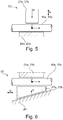
- FIGS. 5 and 6 show exemplary embodiments for a holding mechanism 17 which holds the cable 16a, 16b by means of a force fit.
- a first holding element 27a or a second holding element 27b is moved in a linear actuation direction R from an open position into a holding position.
- the holding element 27a, 27b acts on the rope 16a, 16b with a holding force H and presses it against the first counter-holding element 24a and the second counter-holding element 24b, respectively.
- the holding force H thus acts at a right angle to a longitudinal direction of the cable 16a, 16b and in the direction of the opposing counter-holding element 24a, 24b.
- the holding element 27a, 27b is designed as a clamping wedge, which can be displaced along a ramp 28 in the actuation direction R.
- the ramp 28 here runs parallel to the longitudinal direction of the rope 16a, 16b and rises as seen in the longitudinal direction of the rope 16a, 16b.
- the holding element 27a, 27b is moved towards the rope 16a, 16b in the direction of the holding force H via the ramp 28 and thus presses the rope 16a, 16b against the counter holding element 24a, 24b, which thus is frictionally clamped.
- the wedge-shaped holding element 27a, 27b has a clamping force-reinforcing effect.
- FIG. 7 The illustrated embodiment shows a combined holding mechanism 17 that operates with a force fit and form fit Figure 5 embodiment shown comparable.
- the holding element 27a, 27b is provided on its surface facing the rope 16a, 16b with a profiling that is essentially complementary to the outer surface of the Rope 16a, 16b is formed and thus engages positively in the surface of the rope 16a, 16b.
- the strands 29 of the rope 16a, 16b form a surface of the rope 16a, 16b with a helical and thread-like structure.
- the holding mechanism 17 uses a form fit.
- the holding element 27a, 27b is as in Figures 5 and 7th shifted in operating direction R.
- the cable 16a, 16b is provided, at least in the region of the holding mechanism 17, with shaped pieces 30 which are spaced apart from one another in the longitudinal direction and pressed on one behind the other.
- the holding element 27a, 27b is provided on its surface facing the rope 16a, 16b with a profiling that is complementary to the outer surface of the rope 16a, 16b with its fittings 30 is formed. At least one shaped piece 30 is received by the holding element 27a, 27b in the holding position.
- the counter-holding element 24a, 24b can preferably also be equipped with a profile (not shown) which is suitable for receiving the molded pieces 30 and thus additionally prevents the rope 16a, 16b from being pulled in the pulling direction Z.
- the holding mechanism 17 shown is also essentially a form fit which is used to hold the rope 16a, 16b in place.
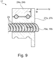
- the Figure 9 shows a holding element 27a, 27b which is applied like a nut to the rope 16a, 16b with its profiled, thread-like outer surface.
- These holding elements 27a, 27b can correspondingly rotate around the thread generated by the rope strands 30 when the rope 16a, 16b is moved in or against the pulling direction Z - for example when extending and retracting the telescopic boom 8.
- the rotational movement of the holding element 27a, 27b is to be blocked in this embodiment.
- a blocking device for example a brake, is to be provided between the counter-holding element 24a, 24b in which the holding element 27a, 27b is rotatably mounted, and the holding element 27a, 27b.
- a blocking device for example a brake
- the holding element 27a, 27b is prevented from rotating, the holding element 27a, 27b holds, comparable to the embodiment according to FIG Figure 7 the rope 16a, 16b against the direction of pull Z.
- guy system 11 also works with chains instead of ropes 16a, 16b, so that in the context of the invention the ropes 16a, 16b are to be understood as flexible traction means.
Landscapes
- Engineering & Computer Science (AREA)
- Mechanical Engineering (AREA)
- Jib Cranes (AREA)
Description
- Die Erfindung betrifft einen Teleskopausleger eines Mobilkrans mit mehreren aus einem Auslegergrundkasten ein- und austeleskopierbaren Teleskopschüssen und mit einem Abspannsystem zum Abspannen des Teleskopauslegers, welches mindestens ein Seil zwischen mindestens einem Spannwerk über mindestens zwei Abspannstützen zu mindestens einem Festpunkt verlaufend aufweist.
- Außerdem betrifft die Erfindung ein Verfahren zum Abspannen eines Teleskopauslegers eines Mobilkrans, bei dem mindestens ein Seil zwischen einem Spannwerk an dem aus einem Auslegergrundkasten und mehreren Teleskopschüssen bestehenden Teleskopausleger und einem Festpunkt am Teleskopausleger abgespannt wird und das mindestens eine Seil über mindestens eine sich an dem Auslegergrundkasten-Kopf oder einem Teleskopschuss-Kopf des Teleskopauslegers abstützende Abspannstütze geführt wird.
- Aus der deutschen Offenlegungsschrift
DE 10 2015 009 156 A1 ist ein teleskopierbarer Kranausleger bekannt. Der Kranausleger besteht aus einem Grundschuss und einem oder mehreren Teleskopschüssen. Um die Tragfähigkeit des Kranauslegers zu erhöhen, ist eine Abspannung aus einem einzelnen Paar Abspannstützen und Zugmitteln vorgesehen. Das Paar Abspannstützen ist v-förmig an einem Kopfende eines ersten Teleskopschusses angeordnet und erstreckt sich rechtwinklig zu dem Kranausleger. Die Zugmittel sind einerseits an einem Fußende des Grundschusses an Seilwinden und andererseits an einem Kopfende eines zweiten Teleskopschusses befestigt. Auch erstrecken sich die beiden Zugmittel entlang des Kranauslegers und sind jeweils über eine der beiden Abspannstützen im Bereich ihrer freien Enden geführt. Hierfür sind an den Abspannstützen jeweils Umlenkrollen angeordnet, die mindestens einmal von dem jeweiligen Seil umschlungen werden. Jede Umlenkrolle kann über eine Haltefunktion fixiert werden. Über die Seilwinden werden die Zugmittel beim Ein- und Ausfahren des Kranauslegers auf- oder abgewickelt und nach erfolgtem Ausfahren gespannt. Nach der Spannung werden auch die Umlenkrollen fixiert. Durch die Spannung der Zugmittel wird der Kranausleger entlastet und ein Durchbiegen des Kranauslegers verringert beziehungsweise vermieden. - Die deutsche Patentschrift
DE 34 47 095 C2 offenbart einen weiteren Teleskopausleger an einem Oberwagen eines Krans. Abgespannt wird der Teleskopausleger durch eine Anordnung aus Spannseilen und Umlenkrollen. Die Spannseile sind jeweils an jedem Kopfende der jeweiligen Teleskopschüsse befestigt und laufen an einem am Oberwagen angebrachten Spannzylinder zusammen. - Aus der europäischen Patentschrift
EP 2 504 267 B1 ist ein Mobilkran mit einem teleskopierbaren Kranausleger mit drei teleskopierbaren Teil-Auslegern bekannt. Die Teil-Ausleger verlaufen parallel und mit Abstand zueinander. Die Beabstandung erfolgt über dreieckige Verbindungsplatten, in deren Ecken die Teil-Ausleger jeweils verlaufen. Die Verbindungsplatten sind jeweils im Bereich von Kopfenden der Teil-Ausleger und an einem Fußende des Grund-Teil-Auslegers angeordnet. - Das Patent
US 4,982,853 A offenbart einen Mobilkran mit einem Teleskopauslegergrundkasten und mehreren Teleskopschüssen, welche ein Abspannsystem tragen. Das Abspannsystem besteht aus drei Seilen und verfügt über zwei Abspannstützen, angebracht am Ende der Teleskopschuss-Köpfe, so dass der Teleskopausleger abgespannt wird. Eines der Seile läuft über Umlenkrollen durch eine der Abspannstützen und ist am Kopf des Teleskopschusses befestigt. Ein Haltemechanismus für eines der Seile wird nicht gezeigt. - In der deutschen Offenlegungsschrift
DE 103 15 989 A1 wird ebenfalls ein Mobilkran mit Teleskopausleger bestehend aus mehreren Teleskopschüssen beschrieben. Zum Ab- beziehungsweise Vorspannen des Teleskopauslegers wird ein Spannseil von einer Seilwinde über eine Rolle an einer ersten Abspannstütze und durch eine zweite Abspannstütze geführt, an einer Rolle an der Spitze des Mastes in den Teleskopausleger hinein umgelenkt und an einer Befestigung festgemacht. Die erste Abspannstütze ist dabei an einem inneren Ende des Auslegergrundkastens befestigt und weist keine Durchgangsöffnung für das Seil auf, sondern eine oberhalb angeordnete Rolle. Auch besitzt nicht jeder Teleskopschuss eine Abspannstütze und Haltemechanismen für das Seil sind nicht vorgesehen. - Aus dem chinesischen Gebrauchsmuster
CN 202 558 505 U ist ein Teleskopausleger mit einem Teleskopauslegergrundkasten sowie mehreren Teleskopschüssen bekannt. - Ein erstes Abspannsystem bestehend aus einer mittig angebrachten Hauptabspannstütze und zwei seitlich angebrachten Abspannstützen ist am Teleskopauslegergrundkasten befestigt. Ein zweites Abspannsystem befindet sich an einem der Teleskopschüsse und besteht ebenso aus drei Abspannstützen, eine mittig und zwei seitlich angeordnet. Seile laufen durch die Abspannstützen und sind am Kopf des Mastes befestigt. Weder ist das erste Abspannsystem am Kopf des Auslegergrundkastens angebracht, noch befindet sich an jedem Teleskopschuss eine Abspannstütze oder Haltemechanismen für die Seile.
- Das deutsche Gebrauchsmuster
DE 202 19 126 U1 offenbart einen Teleskopausleger eines Krans mit einem Teleskopauslegergrundkasten und mehreren Teleskopschüssen. Eine Abspannung ist zum Abspannen des Teleskopauslegers mit zwei Abspannseilen ausgestattet, die über auf Abspannböcken angeordnete Umlenkrollen geführt sind. Eine Abspannstütze an jedem Teleskopschuss und insbesondere am Kopf des Auslegergrundkastens ist jedoch nicht vorgesehen. Auch sind keine Haltemechanismen für die Abspannseile offenbart. - In dem deutschen Gebrauchsmuster
DE 202 08 740 U1 wird ein Abspannsystem für einen Teleskopausleger eines Krans offenbart, wobei zwei Abspannstützen seitlich an einem Grundkasten schwenkbar gelagert sind. Über diese Abspannstützen führen Abspannseile zum Auslegerkopf. An den Abspannseilen sind Verdickungsstücke und an den Abspannstützen entsprechende Seilschlösser vorgesehen, die mit den Verdickungsstücken der Abspannseile in formschlüssigen Eingriff bringbar sind, so dass die Abspannseile an den Abspannstützen 6 fixiert werden können. Der Teleskopausleger wird mit einer Abspannstütze je Seil abgespannt. - Die europäische Patentanmeldung
EP 1 266 861 A1 beschreibt einen Teleskopkran mit Superlifteinrichtung. Die Superlifteinrichtung weist eine Halteeinrichtung für das Zugmittel auf. Es ist jedoch nur ein einziger Abspannbock, angeordnet am Auslegergrundkasten, offenbart. - Auch die europäische Patentanmeldung
EP 1 213 254 A1 offenbart ein Abspannsystem eines Teleskopauslegers. Die vordere Abspannung wird über ihre Länge im Wesentlichen durch eine Anzahl miteinander verbindbarer oder verbundener Zugelemente mit jeweils fixer Länge gebildet. Zur Fixierung der miteinander verbundenen Zugelemente ist eine Verriegelungseinrichtung vorgesehen, die bei ihrer Betätigung das Herausziehen weiterer Zugelemente blockiert. - Die chinesische Patentanmeldung
CN 104 555 760 A offenbart einen Teleskopausleger eines Mobilkrans gemäß dem Oberbegriff des Anspruchs 1, wobei das Seil von einem hinteren Ende des Auslegers über mindestens zwei Abspannböcke je Seil zu einem Festpunkt am vorderen Teil des Auslegers gespannt ist. Jedoch enthält nur der hintere Hauptabspannbock eine Einrichtung, die es ermöglicht, dass das Seil an den Abspannbalken angedrückt wird. - Aus dem deutschen Gebrauchsmuster
DE 202 03 443 U1 ist ein Teleskopausleger mit Abspannsystem bekannt, wobei zwei Abspannstützen seitlich, insbesondere V-förmig, an einem Grundkasten schwenkbar gelagert sind. Im Bereich des freien Endes der Abspannstütze ist eine Seilklemmvorrichtung vorgesehen, die das von der Abspannstütze ablaufende Abspannseil klemmen kann und dadurch Abspannkräfte aufnimmt. Die von der Seilklemmvorrichtung abgefangenen Abspannkräfte des Abspannseils werden über ein zweites Abspannseil abgeleitet, welches von dem freien Ende der Abspannstütze zum Anlenkbereich des Grundkastens oder zum Oberwagen des Mobilkrans führt. - Der Erfindung liegt die Aufgabe zugrunde, einen Teleskopausleger für einen Mobilkran mit einem Abspannsystem und ein Abspannverfahren hierfür zu schaffen, die sich durch eine konstruktiv vereinfachte und leichtere Bauweise sowie eine Erhöhung der Traglast bei unveränderten Teleskopausleger-Maßen auszeichnen.
- Diese Aufgabe wird durch einen Teleskopausleger mit den Merkmalen des Anspruchs 1 und ein Verfahren mit den Merkmalen des Anspruchs 11 gelöst. In den Unteransprüchen 2 bis 10 und 12 sind vorteilhafte Ausgestaltungen der Erfindung angegeben.
- Erfindungsgemäß wird bei einem Teleskopausleger eines Mobilkrans mit mehreren aus einem Auslegergrundkasten ein- und austeleskopierbaren Teleskopschüssen und mit einem Abspannsystem zum Abspannen des Teleskopauslegers, welches mindestens ein Seil zwischen mindestens einem Spannwerk über mindestens zwei Abspannstützen zu mindestens einem Festpunkt verlaufend aufweist und eine Erhöhung der Traglast und eine konstruktiv vereinfachte und leichtere Bauweise dadurch erreicht, dass jede Abspannstütze jeweils am äußeren Ende eines Auslegergrundkasten-Kopfes oder eines Teleskopschuss-Kopfes angeordnet ist und einen Haltemechanismus für das Seil aufweist, wobei der Haltemechanismus mittels Kraft- und/oder Formschluss das Seil hält.. Hierbei sind die Abspannstützen fest an dem Auslegergrundkasten und an mindestens einem der Teleskopschüsse angeordnet. Ein Rüsten des Abspannsystems wird hierdurch nicht notwendig. Durch die höhere Zahl der Abspannstützen kann insgesamt eine leichtere und kompaktere Bauweise, insbesondere Bauhöhe, bei Transport erreicht werden. Auch wird das vollständige Einteleskopieren des Teleskopauslegers nicht durch die Abspannstützen behindert. Dies erlaubt somit eine Reduzierung des Teleskopauslegers auf eine kompakte Größe im Transportzustand.
- In einer weiteren Ausgestaltung der Erfindung ist vorgesehen, dass jeweils am Auslegergrundkasten und an jedem Teleskopschuss eine Abspannstütze angeordnet ist. Der Teleskopausleger kann daher an mehreren Punkten abgespannt werden, welches wiederum die Stabilität der Abspannung erhöht und die Traglast des Teleskopauslegers verbessert. Dadurch kann ferner bei gleicher Traglast eine leichtere und kleinere Bauweise umgesetzt werden.
- Das Abspannsystem wird dadurch konstruktiv vereinfacht, dass jede Abspannstütze eine Durchgangsöffnung für das durchzuführende Seil aufweist.
- Für eine besonders einfache Umsetzung des Abspannsystems ist vorgesehen, dass der Haltemechanismus ein bewegliches Halteelement umfasst, mit dem das Seil in der Durchgangsöffnung gegen ein Gegenhalteelement in einem Betriebszustand festlegbar ist.
- In einer weiteren Ausgestaltung der Erfindung ist vorgesehen, dass das mindestens eine Spannwerk des Abspannsystems an dem Auslegergrundkasten angeordnet ist.
- Eine konstruktive Vereinfachung erfolgt dadurch, dass das Seil an dem Spannwerk und an dem letzten Teleskopschuss-Kopf des letzten Teleskopauslegers festgelegt ist. Dadurch ist ein fest verbautes, platzsparendes Abspannsystem gegeben, welches keine weitere Rüstung erfordert.
- Eine weitere Verbesserung der Stabilität und der Traglast des Teleskopauslegers ist dadurch gegeben, dass ein erstes Spannwerk und zweites Spannwerk an dem Auslegergrundkasten angeordnet sind, die mit einem ersten Seil und einem zweiten Seil zusammenwirken, die zueinander parallel und in Längsrichtung des Teleskopauslegers verlaufen.
- Eine besonders sichere und stabile Abspannung erfolgt dadurch, dass jede Abspannstütze zwei Schenkel umfasst, die in Längsrichtung des Teleskopauslegers gesehen von einer Mitte des Teleskopauslegers rechts und links am Teleskopausleger angeordnet sind und einen Winkel von 45° bis 135°, bevorzugter Weise 90°, einschließen.
- Um den Teleskopausleger in platzsparender und trotzdem stabiler Weise auszuführen, ist vorgesehen, dass die aufeinander folgenden Teleskopschüsse und der Auslegergrundkasten aneinander feststellbar sind.
- Ein vereinfachtes und platzsparendes Verfahren zum Abspannen eines Teleskopauslegers, bei dem mindestens ein Seil zwischen einem Spannwerk an dem aus einem Auslegergrundkasten und mehreren Teleskopschüssen bestehenden Teleskopausleger und einem Festpunkt am Teleskopausleger abgespannt wird und das mindestens eine Seil über mindestens zwei sich an dem Auslegergrundkasten-Kopf oder einem Teleskopschuss-Kopf des Teleskopauslegers abstützende Abspannstützen geführt wird, wird dadurch erreicht, dass die Teleskopschüsse aus dem Auslegergrundkasten ausgefahren werden, das mindestens eine Seil zwischen dem Spannwerk und dem Festpunkt gespannt wird und das mindestens eine Seil über einen Haltemechanismus an jeder Abspannstütze festgelegt wird.
- Eine Verbesserung der Traglast wird durch ein Verfahren dahingehend erreicht, dass ausgehend von einem Transportzustand eines eingefahrenen Teleskopauslegers mit dem in Längsrichtung des Teleskopauslegers letzten Teleskopschuss beginnend und mit dem jeweils angrenzenden Teleskopschuss fortfahrend nach jedem Ausfahren eines Teleskopschusses das mindestens eine Seil des Abspannsystems durch das mindestens eine Spannwerk gespannt und durch den Haltemechanismus festgelegt wird.
- Ein Ausführungsbeispiel der Erfindung wird nachfolgend näher erläutert. Es zeigen:
-
Figur 1 eine perspektivische Ansicht eines Mobilkrans mit einem Teleskopausleger, -
Figur 2 eine perspektivische Teilansicht eines Mobilkrans gemäßFigur 1 mit teilweise ausgefahrenem Teleskopausleger, -
Figur 3 eine perspektivische Draufsicht auf einen komplett ausgefahrenen Teleskopausleger, -
Figur 4 eine Detailansicht einer Abspannstütze am Teleskopausleger, -
Figur 5 eine schematische Darstellung eines Haltemechanismus mittels Kraftschluss, -
Figur 6 eine schematische Darstellung eines weiteren Haltemechanismus mittels Kraftschluss -
Figur 7 eine schematische Darstellung eines Haltemechanismus mittels Kraft- und Formschluss, -
Figur 8 eine schematische Darstellung eines Haltemechanismus mittels Formschluss und -
Figur 9 eine schematische Darstellung eines weiteren Haltemechanismus mittels Formschluss. - In
Figur 1 ist eine perspektivische Ansicht eines mit 1 bezeichneten Mobilkrans abgebildet. Der Mobilkran 1 umfasst im Wesentlichen einen Unterwagen 2 und einen Oberwagen 3. Der Unterwagen 2 trägt Gegengewichte 4 und weist vier Fahrzeugachsen 5 mit je zwei straßentauglichen Rädern 6 auf. Ferner trägt der Unterwagen 2 den Oberwagen 3, welcher bezogen auf den Unterwagen 2 um eine im Wesentlichen vertikal ausgerichtete Drehachse D schwenkbar ist. Oberwagen 3 und Unterwagen 2 können selbstverständlich auch starr aufeinander montiert sein. Am Oberwagen 3 sind eine kombinierte Fahr- und Krankabine 7, die um eine vertikale Achse K von vorne nach hinten und umgekehrt schwenkbar ist, und ein Teleskopausleger 8 angebracht, welcher für eine Straßenfahrt vollständig eingefahren und entgegen einer Vorwärtsfahrtrichtung F des Mobilkrans 1 auf dem Unterwagen 2 nach unten abgelegt ist. Es ist selbstverständlich auch möglich, Fahr- und Krankabine 7 getrennt voneinander auszubilden. - Der Teleskopausleger 8 hat ein Abspannsystem 11, um eine Erhöhung der Traglast bei unveränderten Maßen des Teleskopauslegers 8 zu erreichen, und besteht aus einem Auslegergrundkasten 9 und mehreren Teleskopschüssen 10a-h. Der Auslegergrundkasten 9 ist an seinem Fuß über eine horizontale Wippachse W mit dem Oberwagen 3 verbunden und über einen Wippzylinder 12 aufstellbar (siehe hierzu
Figur 2 ). Auch befinden sich Spannwerke 13a, 13b des Abspannsystems 11 und ein Hubwerk 14 an dem Auslegergrundkasten 9 und somit nicht an dem Oberwagen 3. Die Spannwerke 13a, 13b sind als angetriebene, bremsbare und festlegbare Windwerke mit einem elektrischen oder hydraulischen Antrieb sowie einer Trommel für ein auf- und abzuwickelndes Seil 16a, 16b ausgebildet. Eine Anbringung der Spannwerke 13a, 13b dort und nicht an dem Auslegergrundkasten 9 ist aber auch möglich. Der Auslegergrundkasten 9 nimmt in üblicher Weise die Teleskopschüsse 10a-h in sich auf, welche jeweils ineinander angeordnet und ein- und ausfahrbar sind. Im ausgefahrenen Zustand sind die Teleskopschüsse 10a-h untereinander über Bolzen verbunden. Der Fuß des jeweils inneren und damit kleineren Teleskopschusses 10a-h wird jeweils über ein passendes Verbolzungs-Positionsloch mit dem jeweils nächst äußeren und größeren Teleskopschuss100-109 beziehungsweise Auslegergrundkasten 9 verbolzt. In derFigur 2 ist somit der Fuß des Teleskopschusses 10h mit dem am Kopf 10 befindlichen Verbolzungs-Positionsloch des Teleskopschusses 10g verbunden. Das Abspannsystem 11 umfasst jeweils am in Längsrichtung L des Teleskopauslegers 8 gesehen äußeren Ende eines Kopfes 9a des Auslegergrundkastens 9 und eines Kopfes 10 jedes Teleskopschusses 10a-h angeordnete v-förmige Abspannstützen 15. Jede v-förmige Abspannstütze 15 umfasst einen ersten Schenkel 15a und einen zweiten Schenkel 15b. Die ersten Schenkel 15a und zweiten Schenkel 15b der Abspannstützen 15 sind bei horizontal ausgerichtetem Teleskopausleger 8 gesehen jeweils außen und oben - im Bereich von Ecken der im Querschnitt im wesentlichen viereckigen Teleskopschüsse 10a-h beziehungsweise des im Querschnitt im wesentlichen viereckigen Auslegergrundkastens 9 - angeordnet und erstrecken sich schräg nach oben und außen. Ein Öffnungswinkel a der beiden Schenkel 15a und 15b beträgt dabei in etwa 45-135°, vorzugsweise 90°. Hierbei liegen die beiden Schenkel 15a und 15b in einer gemeinsamen gedachten Ebene, die rechtwinklig zu einer Längsrichtung L des Teleskopauslegers 8 ausgerichtet ist. Die Schenkel 15a und 15b selbst haben eine gestreckt dreieck-ähnliche Form, wobei eine Grundseite des Dreiecks am Teleskopschuss 10a-h beziehungsweise am Auslegergrundkasten 9 anliegt und eine Spitze des Dreiecks mit je einer Durchgangsöffnung 22a und 22b für das erste Seil 16a oder das zweite Seil 16b versehen ist. Die Seile 16a und 16b sind jeweils an dem linken oder dem rechten Schenkel 15a und 15b des letzten, d. h. vom Auslegergrundkasten 9 entferntesten, Teleskopschusses 10h in einem Festpunkt 20a und 20b an der jeweiligen Abspannstütze 15 befestigt. Jeweils über alle rechten und alle linken Schenkel 15a und 15b der Abspannstützen 15 wird eines der beiden Seile 16a und 16b geführt und an einem der am gegenüberliegenden Ende liegenden rechten und linken Spannwerke 13a und 13b (siehe hierzuFigur 2 ) am Fuß des Auslegergrundkastens 9 befestigt und gespannt. Am Ende der Schenkel 15a und 15b des Auslegergrundkastens 9 und der Teleskopschüsse 10a-g, ausgenommen am letzten Teleskopschuss 10h, befindet sich je ein Haltemechanismus 17, der die Seile 16a und 16b nach dem Spannen festlegt. Das Spannen der Seile 16a und 16b erfolgt bevorzugt aus einer Kombination von Spannen über die Spannwerke 13a und 13b, Festhalten in den Haltemechanismen 17 und weiteres Spannen durch Austeleskopieren des jeweiligen Teleskopschuss 10a-h. Grundsätzlich ist es auch denkbar, entweder nur über die Spannwerke 13a und 13b oder durch das Austeleskopieren zu spannen. Letztendlich werden somit die Seile 16a und 16b an mehreren Punkten zwischen den Festpunkten 20a und 20b am letzten Teleskopschuss 10h und den Spannwerken 13a und 13b im Bereich der Abspannstützen 15 festgelegt und gespannt. Das Abspannsystem 11 ist somit fest am Mobilkran 1 verbaut und erfordert keine nachträgliche Rüstung. - In
Figur 2 ist eine perspektivische Teilansicht des Mobilkrans 1 gemäßFigur 1 mit teilweise ausgefahrenem Teleskopausleger 8 abgebildet. Der letzte Teleskopschuss 10h ist ausgefahren; die restlichen Teleskopschüsse 10a-g sind noch eingefahren. Der Oberwagen 3 ist für einen Kranbetrieb aus der Position für die Straßenfahrt (siehe hierzuFigur 1 ) um 180° gedreht, sodass der Teleskopausleger 8 in Vorwärtsfahrtrichtung F zeigt. Die Fahr- und Krankabine 7 ist nun in eine für den Kranbetrieb günstige Position seitlich des Oberwagens 3 verlagert worden. Auf der Oberseite und im Fußbereich des Auslegergrundkastens 9 sind die zwei Spannwerke 13a und 13b im Bereich der Ecken der Teleskopausleger 8 so angeordnet, dass deren Trommel nach oben und außen zeigen und eine Abrollachse der Spannwerke 13a und 13b rechtwinklig zur Längsrichtung L des Teleskopauslegers 8 steht. Darauf folgend, in Richtung des Kopfes 9a des Auslegergrundkastens 9 gesehen, ist das Hubwerk 14 angeordnet. Die Trommel des Hubwerks 14 zeigt nach oben und eine Abrollachse des Hubwerks 14 ist ebenfalls rechtwinklig zur Längsrichtung L des Teleskopauslegers 8 angeordnet. Von dem Hubwerk 14 wird ein Hubseil 18 auf- und abgewickelt, das vom Hubwerk 14 entlang und oberhalb des Teleskopauslegers 8 bis zum Ende des letzten Teleskopschusses 10h verläuft. Am Ende des letzten Teleskopschusses 10h befindet sich eine Umlenkrolle 19, über die das Hubseil 18 geführt wird. - Nachfolgend wird anhand der
Figur 2 die Funktion des Abspannsystems 11 erläutert. In einem ersten Schritt wird der innerste Teleskopschuss 10h des Teleskopauslegers 8 ausgefahren und gleichzeitig die in den Festpunkten 20a, 20b der Schenkel 15a und 15b der Abspannstütze 15 des innerste Teleskopschusses 10h festgelegten Seile 16a, 16b in Längsrichtung L des Teleskopauslegers 8 mitgenommen und somit von den Spannwerken 13a, 13b abgewickelt. Hierbei werden die Seile 16a, 16b durch die Durchgangsöffnungen 22a, 22b der Abspannstützen 15 der anderen noch nicht ausgefahrenen Teleskopschüsse 10a-g geführt. Im eingefahrenen Zustand der Teleskopschüsse 10a-h liegen die Abspannstützen 15 mit geringem Abstand eng aneinander. Kurz vor Erreichen einer gewünschten Verbolzungsposition des innersten Teleskopschusses 10h werden die Seile 16a, 16b, die bereits über die Spannwerke 13a, 13b mit einer Grundspannung beaufschlagt sind, durch die beiden Haltemechanismen 17 des benachbarten Teleskopschusses 10g an den Schenkeln 15a und 15b festgelegt. Durch weiteres Ausfahren des Teleskopschusses 10h in seine Verbolzungsposition für den vollen Ausfahrweg wird dann der obere Teil der Seile 16a, 16b zwischen den Festpunkten 20a, 20b der Schenkel 15a und 15b der Abspannstütze 15 des innerste Teleskopschusses 10h und den beiden Haltemechanismen 17 des benachbarten Teleskopschusses 10g weiter gespannt. Grundsätzlich können je Teleskopschuss 10a-h verschiedene Verbolzungspositionen vorgesehen werden, die dann einen Teleskopschuss 10a-h in einem vollen oder halben oder sonst vorab gewählten Ausfahrweg des Teleskopschusses 10a-h festlegen. Parallel mit dem Ausfahren und Verbolzen der weiteren Teleskopschüsse 10a-g werden dann in gleicher Weise sukzessive und abschnittweise die Seile 16a, 16b zwischen den jeweiligen Abspannstützen 15 der Teleskopschüsse 10a-g und des Auslegergrundkastens 9 gespannt. Wichtig ist hierbei, dass das Abspannen der Seile 16a, 16b nicht nur zwischen den Befestigungspunkten 20a und 20b und den Spannwerken 13a und 13b, sondern auch zwischen den hierzu benachbarten Abspannstützen 15 und jeweils zwischen den benachbarten Abspannstützen 15 erfolgt. - In
Figur 3 ist eine perspektivische Draufsicht auf einen komplett ausgefahrenen Teleskopausleger 8 abgebildet. Die Abspannstützen 15 sind an jedem Teleskopschuss-Kopf 10 und am Auslegergrundkasten-Kopf 9a und somit beabstandet zueinander angeordnet. Die Schenkel 15a und 15b der Abspannstütze 15 sind seitlich rechts und links am Teleskopausleger 8 angeordnet. Die Seile 16a und 16b sind an den Schenkeln 15a und 15b der Abspannstütze 15 des letzten Teleskopschusses 10h an einem ersten und zweiten Festpunkt 20a und 20b befestigt. Das zwischen den Schenkeln 15a und 15b des letzten Teleskopschusses 10h verlaufende Hubseil 18 verläuft unterhalb der Schenkel 15a und 15b über eine Umlenkrolle 19 und dann über eine Führungsrolle 21. - Die
Figur 4 zeigt eine Detailansicht der Schenkel 15a und 15b einer Abspannstütze 15 des Teleskopauslegers 8. Der Haltemechanismus 17 besteht jeweils im Wesentlichen aus einem ersten Gegenhalteelement 24a beziehungsweise zweiten Gegenhalteelement 24b, die jeweils mit einem ersten Halteelement 27a, insbesondere in Form einer Seilrolle, beziehungsweise einem zweiten Halteelement 27b, insbesondere in Form einer Seilrolle, zusammenwirken, um das jeweilige Seil 16a, 16b dazwischen festzuhalten beziehungsweise einzuklemmen. Das Gegenhalteelement 24a, 24b ist jeweils als ortsfeste Anlagefläche des jeweiligen Schenkels 15a und 15b ausgebildet und befindet sich jeweils an einem vom Teleskopausleger 8 abgewandten Ende der Schenkel 15a und 15b und angrenzend zu den Durchgangsöffnungen 22a und 22b. Die Anlagefläche ist an die Kontur des Seils 16a, 16b angepasst und kann einen erhöhten Reibungswiderstand aufweisen. Um die Halteelemente 27a, 27b in einer Schieberichtung S, die parallel zur Längserstreckung der Schenkel 15a und 15b verläuft, in Richtung der Gegenhalteelemente 24a, 24b bewegen zu können, nimmt jeder der Schenkel 15a und 15b ein stabförmiges Schiebeelement 25a, 25b auf. Das Schiebeelement 25a, 25b ist somit jeweils im Schenkel 15a und 15b integriert und nimmt an seinem dem Teleskopausleger 8 abgewandten Ende jeweils eine der Halteelemente 27a, 27b auf. Um das Seil 16a, 16b mittels der Halteelemente 27a, 27b an die Gegenhalteelemente 24a, 24b drücken zu können, ist das Schiebeelement 25a, 25b entlang des Schenkels 15a und 15b der Abspannstütze 15 verschiebbar. Eine Verschiebebewegung wird durch eine an dem Teleskopausleger 8 zugewandten Ende des Schiebeelements 25a, 25b angeordnete Laufrolle 26a, 26b erreicht, die in Längsrichtung L entlang der äußeren Oberfläche des Teleskopauslegers 8 abrollt und im Bereich der vorgewählten Verbolzungsposition auf keilförmige Führungselemente 23a, 23b in Form von Erhöhungen auf der äußeren Oberfläche des Teleskopauslegers 8 und somit eine Bewegung des Schiebeelements 25a, 25b in Schieberichtung S bewirken, so dass eine Festlegung beziehungsweise Klemmung des Seils 16a, 16b im Bereich der Verbolzungsposition erreicht wird. Um Verbolzungspositionen überfahren zu können, ohne eine Spannung des Seiles 16a, 16b zu bewirken, wird nur eine Grundspannung auf das Seil 16a, 16b über die Spannwerke13a, 13b gegeben, wenn anschließend auch eine weitere Spannung über den Haltemechanismus 17 erfolgen soll. Ohne die Grundspannung wird das Seil 16a, 16b beim Überfahren einer nicht gewählten Verbolzungsposition nur durch das Führungselement 23a, 23b kurz im ungespannten Zustand geklemmt und sofort wieder gelöst. - In dem Ausführungsbeispiel beträgt die Breite b etwa 200 cm und die Länge l der Schenkel 15a, 15b etwa 95 cm. Diese Maße können natürlich anders ausgelegt werden. Bei der Festlegung der Abmessungen der Abspannstützen 15 muss je nach Größe des Teleskopauslegers 8 und des Mobilkrans 1 (Kranlänge, Kranbreite, mögliche Auslegerwinkelablage) der richtige Kompromiss gefunden werden, um eine Traglasterhöhung zu erreichen ohne die gesetzliche Fahrzeugbreite und -höhe für den Straßenbetrieb zu überschreiten.
- Vorstehend ist der Haltemechanismus 17 in einer mechanischen Ausführung beschrieben. Grundsätzlich ist es auch vorstellbar, die Haltemechanismen 17 elektrisch, hydraulisch oder pneumatisch anzutreiben. Auch können anstatt der Halteelemente 27a, 27b und der Laufrollen 26a, 26b Gleitelemente vorgesehen werden. Die Führungselemente 23a, 23b, welche bevorzugterweise als Keile ausgeführt sind, und die Schiebelemente 25a, 25b können durch andere Elemente ersetzt werden, die die relative Bewegung der Teleskopschüsse 10a-h zueinander beim Ein-und Ausfahren in eine Festlegung des Seils 16a, 16b, vorzugsweise durch Klemmen, festsetzen.
- In den
Figuren 5 bis 9 sind zusätzlich zu der inFigur 4 beschriebenen Ausführungsform fünf weitere Ausführungsformen für einen Haltemechanismus 17 dargestellt. Die Erfindung ist jedoch nicht auf diese fünf beispielhaften Ausführungsformen zu beschränken. - Grundsätzlich kann über die von dem Haltemechanismus 17 aufgebrachte Haltekraft H das Seil 16a, 16b durch Kraftschluss (Reibschluss) und/oder durch Formschluss über den Haltemechanismus 17 an der Abspannstütze 15 gehalten werden.
- Die
Figuren 5 und 6 zeigen beispielhafte Ausführungsformen für einen Haltemechanismus 17, der mittels Kraftschluss das Seil 16a, 16b hält. Hierfür wird ein erstes Halteelement 27a beziehungsweise ein zweites Halteelement 27b in einer linearen Betätigungsrichtung R aus einer Offenstellung in eine Haltestellung bewegt. In der Haltestellung beaufschlagt das Halteelement 27a, 27b mit einer Haltekraft H das Seil 16a, 16b und drückt dieses gegen das erste Gegenhalteelement 24a beziehungsweise und das zweite Gegenhalteelement 24b. Entsprechender Weise wirkt die Haltekraft H somit in einem rechten Winkel zur einer Längsrichtung des Seils 16a, 16b und in Richtung des gegenüberliegenden Gegenhalteelements 24a, 24b. - In der
Figur 5 wird das Seil 16a, 16b zwischen dem in Betätigungsrichtung R geschobenen Halteelement 27a, 27b und dem Gegenhalteelement 24a, 24b kraftschlüssig eingeklemmt. - In der
Figur 6 ist das Halteelement 27a, 27b als Klemmkeil ausgebildet, der entlang einer Rampe 28 in Betätigungsrichtung R verschiebbar ist. Die Rampe 28 verläuft hierbei parallel zur Längsrichtung des Seils 16a, 16b und steigt in Längsrichtung des Seils 16a, 16b gesehen an. Über eine Bewegung des Halteelements 27a, 27b in die Haltestellung wird über die Rampe 28 das Halteelement 27a, 27b in Richtung der Haltekraft H auf das Seil 16a, 16b zubewegt und drückt das Seil 16a, 16b somit gegen das Gegenhalteelement 24a, 24b, das somit kraftschlüssig eingeklemmt wird. Zusätzlich hat das keilförmige Halteelement 27a, 27b eine klemmkraftverstärkende Wirkung. Wird das Seil 16a, 16b weiter in Zugrichtung Z gezogen, nimmt diese über Reibschluss das keilförmige Halteelement 27a, 27b mit. Dieses bewegt sich dadurch die Rampe 28 weiter hoch und erhöht die Haltekraft H in Richtung des Seils 16a, 16b. - Das in
Figur 7 dargestellte Ausführungsbeispiel zeigt einen kombinierten, mit Kraft- und Formschluss arbeitenden Haltemechanismus 17. Grundsätzlich ist dieser mit der inFigur 5 gezeigten Ausführungsform vergleichbar. Zusätzlich ist jedoch das Halteelement 27a, 27b an seiner dem Seil 16a, 16b zugewandten Fläche mit einer Profilierung versehen, die im Wesentlichen komplementär zu äußeren Oberfläche des Seils 16a, 16b ausgebildet ist und somit formschlüssig in die Oberfläche des Seils 16a, 16b eingreift. Hierbei bilden die Litzen 29 des Seils 16a, 16b eine Oberfläche des Seils 16a, 16b mit einer wendelförmigen sowie gewindeartigen Struktur. - Auch der Haltemechanismus 17 gemäß dem Ausführungsbeispiel in
Figur 8 nutzt einen Formschluss. Das Halteelement 27a, 27b wird dabei wie inFiguren 5 und7 in Betätigungsrichtung R verschoben. Das Seil 16a, 16b ist zumindest im Bereich des Haltemechanismus 17 mit in Längsrichtung voneinander beabstandeten und hintereinander aufgepressten Formstücken 30 versehen. Um statt eines Kraftschlusses einen Formschluss zwischen dem Halteelements 27a, 27b herstellen zu können, ist das Halteelement 27a, 27b an seiner dem Seil 16a, 16b zugewandten Fläche mit einer Profilierung versehen, die komplementär zu der äußeren Oberfläche des Seils 16a, 16b mit seinen Formstücken 30 ausgebildet ist. Zumindest ein Formstück 30 wird von dem Halteelement 27a, 27b in der Haltestellung aufgenommen. Bei Bedarf können es auch mehrere sein. Vorzugsweise kann zusätzlich zum Halteelement 27a, 27b auch das Gegenhalteelement 24a, 24b mit einer Profilierung ausgestattet sein (nicht dargestellt), die zum Aufnehmen der Formstücke 30 geeignet ist und somit das Seil 16a, 16b zusätzlich daran hindert, in Zugrichtung Z gezogen zu werden. - Bei dem in
Figur 9 dargestellten Haltemechanismus 17 handelt es sich ebenfalls im Wesentlichen um einen Formschluss, welcher zum Festhalten des Seils 16a, 16b verwendet wird. DieFigur 9 zeigt ein Halteelement 27a, 27b, das nach Art einer Mutter auf das Seil 16a, 16b mit seiner profilierten, gewindeartigen äußeren Oberfläche aufgebracht ist. Diese Halteelemente 27a, 27b können entsprechend um das durch die Seillitzen 30 erzeugte Gewinde rotieren, wenn das Seil 16a, 16b in oder gegen die Zugrichtung Z bewegt wird - beispielsweise beim Aus- und Einfahren des Teleskopauslegers 8. Um den Haltemechanismus 17 aus seiner Offenstellung in seine Haltestellung zu bewegen, ist bei dieser Ausführungsform die Drehbewegung des Halteelements 27a, 27b zu blockieren. Hierfür ist zwischen dem Gegenhalteelement 24a, 24b, in dem das Halteelement 27a, 27b drehend gelagert ist, und dem Halteelement 27a, 27b eine Blockiervorrichtung, beispielsweise eine Bremse, vorzusehen. Diese ist in derFigur 9 durch den Pfeil B angedeutet. Wenn das Halteelement 27a, 27b daran gehindert wird sich zu drehen, hält das Halteelement 27a, 27b vergleichbar mit der Ausführung gemäßFigur 7 das Seil 16a, 16b entgegen der Zugrichtung Z. - Außerdem ist selbstverständlich, dass das Abspannsystem 11 auch mit Ketten anstatt mit Seilen 16a, 16b funktioniert, sodass im Sinne der Erfindung die Seile 16a, 16b als biegeschlaffe Zugmittel zu verstehen sind.
-
- 1
- Mobilkran
- 2
- Unterwagen
- 3
- Oberwagen
- 4
- Gegengewicht
- 5
- Fahrzeugachse
- 6
- Räder
- 7
- Fahr- und Krankabine
- 8
- Teleskopausleger
- 9
- Auslegergrundkasten
- 9a
- Auslegergrundkasten-Kopf
- 10
- Teleskopschuss-Kopf
- 10a-h
- Teleskopschüsse
- 11
- Abspannsystem
- 12
- Wippzylinder
- 13a
- erstes Spannwerk
- 13b
- zweites Spannwerk
- 14
- Hubwerk
- 15
- Abspannstütze
- 15a
- erster Schenkel
- 15b
- zweiter Schenkel
- 16a
- erstes Seil
- 16b
- zweites Seil
- 17
- Haltemechanismus
- 18
- Hubseil
- 19
- Umlenkrolle
- 20a
- erster Festpunkt
- 20b
- zweiter Festpunkt
- 21
- Führungsrolle
- 22a
- erste Durchgangsöffnung
- 22b
- zweite Durchgangsöffnung
- 23a
- erstes Führungselement
- 23b
- zweites Führungselement
- 24a
- erstes Gegenhalteelement
- 24b
- zweites Gegenhalteelement
- 25a
- erstes Schiebeelement
- 25b
- zweites Schiebeelement
- 26a
- erste Laufrolle
- 26b
- zweite Laufrolle
- 27a
- erstes Halteelement
- 27b
- zweites Halteelement
- 28
- Rampe
- 29
- Litzen
- 30
- Formstück
- a
- Öffnungswinkel
- b
- Breite
- B
- Pfeil
- D
- Drehachse
- F
- Vorwärtsfahrtrichtung
- l
- Länge
- H
- Haltekraft
- K
- Schwenkachse
- L
- Längsrichtung
- R
- Betätigungsrichtung
- S
- Schieberichtung
- W
- Wippachse
- Z
- Zugrichtung des Seils
Claims (12)
- Teleskopausleger (8) eines Mobilkrans (1) mit mehreren aus einem Auslegergrundkasten (9) ein- und austeleskopierbaren Teleskopschüssen (10a-h) und mit einem Abspannsystem (11) zum Abspannen des Teleskopauslegers (8), welches mindestens ein Seil (16a, 16b) zwischen mindestens einem Spannwerk (13a, 13b) über mindestens zwei Abspannstützen (15) zu mindestens einem Festpunkt (20a, 20b) verlaufend aufweist, dadurch gekennzeichnet, dass jede Abspannstütze (15) jeweils am äußeren Ende eines Auslegergrundkasten-Kopfes (9a) oder eines Teleskopschuss-Kopfes (10) angeordnet ist und einen Haltemechanismus (17) für das Seil (16a, 16b) aufweist, wobei der Haltemechanismus (17) mittels Kraft- und/oder Formschluss das Seil (16a, 16b) hält.
- Teleskopausleger (8) nach Anspruch 1, dadurch gekennzeichnet, dass eine weitere Abspannstütze (15) an dem Teleskopschuss-Kopf (10) des innersten Teleskopschusses (10h) den Festpunkt (20a, 20b) trägt.
- Teleskopausleger (8) nach einem der Ansprüche 1 oder 2, dadurch gekennzeichnet, dass jeweils am Auslegergrundkasten (9) und an jedem Teleskopschuss (10a-h) eine Abspannstütze (15) angeordnet ist.
- Teleskopausleger (8) nach einem der Ansprüche 1 bis 3, dadurch gekennzeichnet, dass jede Abspannstütze (15) eine Durchgangsöffnung (22a, 22b) für das durchzuführende Seil (16a, 16b) aufweist.
- Teleskopausleger (8) nach Anspruch 4, dadurch gekennzeichnet, dass der Haltemechanismus (17) ein bewegliches Halteelement (27a, 27b) umfasst, mit dem das Seil (16a, 16b) in der Durchgangsöffnung (22a, 22b) gegen ein Gegenhalteelement (24a, 24b) in einem Betriebszustand festlegbar ist.
- Teleskopausleger (8) nach einem der Ansprüche 1 bis 5, dadurch gekennzeichnet, dass das mindestens eine Spannwerk (13a, 13b) des Abspannsystems (11) an dem Auslegergrundkasten (9) angeordnet ist.
- Teleskopausleger (8) nach einem der Ansprüche 1 bis 6, dadurch gekennzeichnet, dass das Seil (16a, 16b) an dem Spannwerk (13a, 13b) und an dem letzten Teleskopschuss-Kopf (10) des letzten Teleskopauslegers (10h) festgelegt ist.
- Teleskopausleger (8) nach einem der Ansprüche 1 bis 7, dadurch gekennzeichnet, dass ein erstes Spannwerk (13a) und zweites Spannwerk (13b) an dem Auslegergrundkasten (9) angeordnet sind, die mit einem ersten Seil (16a) und einem zweiten Seil (16b) zusammenwirken, die zueinander parallel und in Längsrichtung (L) des Teleskopauslegers (8) verlaufen.
- Teleskopausleger (8) nach Anspruch 8, dadurch gekennzeichnet, dass jede Abspannstütze (15) zwei Schenkel (15a, 15b) umfasst, die in Längsrichtung (L) des Teleskopauslegers (8) gesehen von einer Mitte des Teleskopauslegers (8) rechts und links am Teleskopausleger (8) angeordnet sind und einen Winkel (a) von 45° bis 135°, bevorzugterweise 90°, einschließen.
- Teleskopausleger (8) nach einem der Ansprüche 1 bis 9, dadurch gekennzeichnet, dass die aufeinander folgenden Teleskopschüsse (10a-h) und der Auslegergrundkasten (9) aneinander feststellbar sind.
- Verfahren zum Abspannen eines Teleskopauslegers eines Mobilkrans, insbesondere nach einem der Ansprüche 1 bis 10, bei dem mindestens ein Seil (16a, 16b) zwischen einem Spannwerk (13a, 13b) an dem aus einem Auslegergrundkasten (9) und mehreren Teleskopschüssen (10a-h) bestehenden Teleskopausleger (8) und einem Festpunkt (20a, 20b) am Teleskopausleger (8) abgespannt wird und das mindestens eine Seil (16a, 16b) über mindestens zwei sich an dem Auslegergrundkasten-Kopf (9a) oder einem Teleskopschuss-Kopf (10) des Teleskopauslegers (8) abstützende Abspannstützen (15) geführt wird, dadurch gekennzeichnet, dass die Teleskopschüsse (10a-h) aus dem Auslegergrundkasten (9) ausgefahren werden, das mindestens eine Seil (16a, 16b) zwischen dem Spannwerk (13a, 13b) und dem Festpunkt (20a, 20b) gespannt wird und das mindestens eine Seil (16a, 16b) über einen Haltemechanismus (17) an jeder Abspannstütze (10) festgelegt wird.
- Verfahren nach Anspruch 11, dadurch gekennzeichnet, dass ausgehend von einem Transportzustand eines eingefahrenen Teleskopauslegers (8) mit dem in Längsrichtung (L) des Teleskopauslegers (8) letzten Teleskopschuss (10h) beginnend und mit dem jeweils angrenzenden Teleskopschuss (10a-10g) fortfahrend nach jedem Ausfahren eines Teleskopschusses (10a-h) das mindestens eine Seil (16a, 16b) des Abspannsystems (11) durch das mindestens eine Spannwerk (13a, 13b) gespannt und durch den Haltemechanismus (17) festgelegt wird.
Applications Claiming Priority (2)
| Application Number | Priority Date | Filing Date | Title |
|---|---|---|---|
| DE102016114837.7A DE102016114837A1 (de) | 2016-08-10 | 2016-08-10 | Teleskopausleger mit Abspannsystem für einen Mobilkran und Abspannverfahren hierfür |
| PCT/EP2017/070348 WO2018029306A1 (de) | 2016-08-10 | 2017-08-10 | Teleskopausleger mit abspannsystem für einen mobilkran und abspannverfahren hierfür |
Publications (2)
| Publication Number | Publication Date |
|---|---|
| EP3464156A1 EP3464156A1 (de) | 2019-04-10 |
| EP3464156B1 true EP3464156B1 (de) | 2020-09-30 |
Family
ID=59579647
Family Applications (1)
| Application Number | Title | Priority Date | Filing Date |
|---|---|---|---|
| EP17751101.1A Active EP3464156B1 (de) | 2016-08-10 | 2017-08-10 | Teleskopausleger mit abspannsystem für einen mobilkran und abspannverfahren hierfür |
Country Status (6)
| Country | Link |
|---|---|
| US (1) | US11174137B2 (de) |
| EP (1) | EP3464156B1 (de) |
| JP (1) | JP7085710B2 (de) |
| CN (1) | CN109562922B (de) |
| DE (1) | DE102016114837A1 (de) |
| WO (1) | WO2018029306A1 (de) |
Families Citing this family (7)
| Publication number | Priority date | Publication date | Assignee | Title |
|---|---|---|---|---|
| DE102017101113B3 (de) | 2017-01-20 | 2018-07-12 | Terex Global Gmbh | Teleskopausleger mit Stangenabspannsystem für einen Mobilkran und Abspannverfahren hierfür |
| DE102018116575A1 (de) * | 2018-07-09 | 2020-01-09 | Terex Global Gmbh | Stütze für den hinteren Abspannstrang eines Teleskopkrans |
| DE102019122071B3 (de) * | 2019-08-16 | 2020-09-17 | Tadano Demag Gmbh | Teleskopausleger mit ausklappbarem Mast |
| DE102020129454B4 (de) | 2020-11-09 | 2023-08-17 | Tadano Demag Gmbh | Fahrzeugkran mit einem Auslegersystem |
| DE102020129762B3 (de) | 2020-11-11 | 2022-02-17 | Tadano Demag Gmbh | Teleskopausleger eines Mobilkrans |
| DE102020134714B4 (de) | 2020-12-22 | 2023-09-28 | Tadano Demag Gmbh | Fahrzeugkran mit einem wippbaren Hauptausleger und mit einem Zusatzauslegersystem |
| DE102022102318A1 (de) * | 2022-02-01 | 2023-08-03 | Liebherr-Werk Ehingen Gmbh | Mobilkran mit abgespanntem Teleskopausleger |
Family Cites Families (28)
| Publication number | Priority date | Publication date | Assignee | Title |
|---|---|---|---|---|
| US1325053A (en) * | 1919-12-16 | Telescoping tower | ||
| US2449703A (en) * | 1948-09-21 | Snatch block | ||
| US3830376A (en) | 1973-02-16 | 1974-08-20 | Harnischfeger Corp | Telescopic jib and bearing means therefor |
| US4004695A (en) | 1975-04-16 | 1977-01-25 | Fulton Industries, Inc. | Channel and plate telescopic crane boom |
| DE2917829A1 (de) * | 1979-05-03 | 1980-11-13 | Gottwald Kg Leo | Fahrzeugkran mit teleskopausleger |
| DE3447095C2 (de) | 1984-12-22 | 1995-04-06 | Krupp Ag Hoesch Krupp | Teleskopausleger für Krane |
| US4982853A (en) * | 1989-02-09 | 1991-01-08 | Hikoma Seisakusho Co., Ltd. | Reinforcement mechanism for multi-stage telescopic boom |
| DE10022658B4 (de) | 1999-06-28 | 2007-10-04 | Terex-Demag Gmbh & Co. Kg | Teleskopkran |
| DE10062517C2 (de) | 2000-12-11 | 2002-12-05 | Demag Mobile Cranes Gmbh & Co | Teleskopausleger |
| DE20020974U1 (de) * | 2000-12-12 | 2002-04-25 | Liebherr-Werk Ehingen Gmbh, 89584 Ehingen | Fahrzeugkran |
| DE10129022B4 (de) | 2001-06-13 | 2005-07-28 | Terex-Demag Gmbh & Co. Kg | Teleskopkran mit Superlifteinrichtung |
| DE20203443U1 (de) | 2002-01-02 | 2003-05-15 | Liebherr-Werk Ehingen Gmbh, 89584 Ehingen | Teleskopausleger |
| DE20208740U1 (de) * | 2002-06-05 | 2003-10-09 | Liebherr-Werk Ehingen Gmbh, 89584 Ehingen | Teleskopausleger eines Krans |
| DE20219126U1 (de) | 2002-12-10 | 2004-04-15 | Liebherr-Werk Ehingen Gmbh | Teleskopausleger |
| DE10315989B4 (de) * | 2003-04-08 | 2007-10-25 | Grove U.S. Llc | Spannsystem für einen Mobil-Teleskopkran |
| EP1666401B1 (de) | 2004-12-03 | 2011-06-22 | Manitowoc Crane Group Germany GmbH | Fahrzeugkran |
| JP4683938B2 (ja) | 2005-01-27 | 2011-05-18 | 株式会社タダノ | 移動式クレーンの伸縮ブーム縦撓み抑制装置 |
| CN201272663Y (zh) * | 2008-06-30 | 2009-07-15 | 徐州重型机械有限公司 | 伸缩臂起重机及其超起装置 |
| CN101857176B (zh) * | 2010-07-05 | 2013-04-10 | 三一汽车起重机械有限公司 | 超起装置和具有该装置的伸缩臂起重设备 |
| RU2547492C2 (ru) | 2010-12-17 | 2015-04-10 | Тадано Фаун Гмбх | Передвижной телескопический подъемный кран |
| CN202558505U (zh) * | 2012-05-17 | 2012-11-28 | 中联重科股份有限公司 | 超起装置和起重机 |
| DE202014006460U1 (de) | 2014-08-11 | 2015-11-12 | Liebherr-Werk Ehingen Gmbh | Teleskopausleger eines Krans mit Abspannung sowie Kran |
| CN104555760B (zh) | 2014-12-26 | 2016-07-27 | 长沙中联消防机械有限公司 | 伸缩臂架结构和工程车辆 |
| DE102015202734A1 (de) | 2015-02-16 | 2016-08-18 | Terex Cranes Germany Gmbh | Kran und Verfahren zum Beeinflussen einer Verformung eines Auslegersystems eines derartigen Krans |
| DE102015119379B3 (de) | 2015-11-10 | 2017-03-30 | Terex Global Gmbh | Mobilkran und Verfahren zum Abwinkeln einer Hauptauslegerverlängerung relativ zu einem Hauptausleger eines Mobilkrans |
| DE102015119381B3 (de) | 2015-11-10 | 2017-04-27 | Terex Global Gmbh | Mobilkran und Verfahren zum Abwinkeln einer Hauptauslegerverlängerung relativ zu einem Hauptausleger eines Mobilkrans |
| DE102015120350B3 (de) | 2015-11-24 | 2017-05-24 | Terex Global Gmbh | Mobilkran zum Abwinkeln einer Hauptauslegerverlängerung relativ zu einem Hauptausleger eines Mobilkrans |
| DE102017101113B3 (de) | 2017-01-20 | 2018-07-12 | Terex Global Gmbh | Teleskopausleger mit Stangenabspannsystem für einen Mobilkran und Abspannverfahren hierfür |
-
2016
- 2016-08-10 DE DE102016114837.7A patent/DE102016114837A1/de not_active Withdrawn
-
2017
- 2017-08-10 JP JP2019506423A patent/JP7085710B2/ja active Active
- 2017-08-10 US US16/323,712 patent/US11174137B2/en active Active
- 2017-08-10 EP EP17751101.1A patent/EP3464156B1/de active Active
- 2017-08-10 CN CN201780047882.9A patent/CN109562922B/zh active Active
- 2017-08-10 WO PCT/EP2017/070348 patent/WO2018029306A1/de not_active Ceased
Non-Patent Citations (1)
| Title |
|---|
| None * |
Also Published As
| Publication number | Publication date |
|---|---|
| US11174137B2 (en) | 2021-11-16 |
| CN109562922B (zh) | 2020-05-01 |
| EP3464156A1 (de) | 2019-04-10 |
| JP2019524603A (ja) | 2019-09-05 |
| US20200189888A1 (en) | 2020-06-18 |
| JP7085710B2 (ja) | 2022-06-17 |
| CN109562922A (zh) | 2019-04-02 |
| DE102016114837A1 (de) | 2018-02-15 |
| WO2018029306A1 (de) | 2018-02-15 |
Similar Documents
| Publication | Publication Date | Title |
|---|---|---|
| DE10022658B4 (de) | Teleskopkran | |
| WO2018029306A1 (de) | Teleskopausleger mit abspannsystem für einen mobilkran und abspannverfahren hierfür | |
| EP3519344B1 (de) | Teleskopausleger mit stangenabspannsystem für einen mobilkran und abspannverfahren hierfür | |
| DE10129022B4 (de) | Teleskopkran mit Superlifteinrichtung | |
| EP3587337B1 (de) | Teleskopausleger-abspanneinrichtung | |
| DE2252836C2 (de) | Turmdrehkran | |
| EP3360841A1 (de) | Hubvorrichtung | |
| EP3448796B1 (de) | Kran mit einer gegengewichtsverstellvorrichtung sowie verfahren zum verstellen eines gegengewichts an einem kran | |
| EP0669279B1 (de) | Teleskopierstab | |
| DE10062517C2 (de) | Teleskopausleger | |
| DE102015009156B4 (de) | Teleskopausleger eines Krans mit Abspannung sowie Kran | |
| DE1506519C2 (de) | Teleskopausleger | |
| DE3513405A1 (de) | Teleskopmast mit selbsttaetig ver- und entriegelbaren einzelschuessen | |
| DE3343343A1 (de) | Kranausleger | |
| DE20208740U1 (de) | Teleskopausleger eines Krans | |
| CH667447A5 (de) | Oben drehender turmdrehkran. | |
| DE2628016C2 (de) | Mobilkran mit Teleskophauptausleger | |
| WO2021032529A1 (de) | Teleskopausleger mit ausklappbarem mast | |
| DE102009032426B3 (de) | Vorrichtung zur Montage und/oder Demontage von Ballast an einem Kran und Turmdrehkran mit einer derartigen Vorrichtung | |
| DE20023869U1 (de) | Teleskopkran | |
| DE2628868C2 (de) | Teleskopierbares Auslegersystem für Förderanlagen, insbesondere Saugheber | |
| EP4053066A2 (de) | Vorrichtung und verfahren zur montage / demontage eines mobilkranauslegers | |
| DE2326022B1 (de) | Straßenverfahrbarer Turmdrehkraa | |
| DE2224453C3 (de) | Zusammenklappbarer Turmdrehkran | |
| DE1456454C (de) | Turmdrehkran |
Legal Events
| Date | Code | Title | Description |
|---|---|---|---|
| STAA | Information on the status of an ep patent application or granted ep patent |
Free format text: STATUS: UNKNOWN |
|
| STAA | Information on the status of an ep patent application or granted ep patent |
Free format text: STATUS: THE INTERNATIONAL PUBLICATION HAS BEEN MADE |
|
| PUAI | Public reference made under article 153(3) epc to a published international application that has entered the european phase |
Free format text: ORIGINAL CODE: 0009012 |
|
| STAA | Information on the status of an ep patent application or granted ep patent |
Free format text: STATUS: REQUEST FOR EXAMINATION WAS MADE |
|
| 17P | Request for examination filed |
Effective date: 20181213 |
|
| AK | Designated contracting states |
Kind code of ref document: A1 Designated state(s): AL AT BE BG CH CY CZ DE DK EE ES FI FR GB GR HR HU IE IS IT LI LT LU LV MC MK MT NL NO PL PT RO RS SE SI SK SM TR |
|
| AX | Request for extension of the european patent |
Extension state: BA ME |
|
| DAV | Request for validation of the european patent (deleted) | ||
| DAX | Request for extension of the european patent (deleted) | ||
| GRAP | Despatch of communication of intention to grant a patent |
Free format text: ORIGINAL CODE: EPIDOSNIGR1 |
|
| STAA | Information on the status of an ep patent application or granted ep patent |
Free format text: STATUS: GRANT OF PATENT IS INTENDED |
|
| INTG | Intention to grant announced |
Effective date: 20200402 |
|
| GRAS | Grant fee paid |
Free format text: ORIGINAL CODE: EPIDOSNIGR3 |
|
| GRAA | (expected) grant |
Free format text: ORIGINAL CODE: 0009210 |
|
| STAA | Information on the status of an ep patent application or granted ep patent |
Free format text: STATUS: THE PATENT HAS BEEN GRANTED |
|
| RAP1 | Party data changed (applicant data changed or rights of an application transferred) |
Owner name: TADANO DEMAG GMBH |
|
| AK | Designated contracting states |
Kind code of ref document: B1 Designated state(s): AL AT BE BG CH CY CZ DE DK EE ES FI FR GB GR HR HU IE IS IT LI LT LU LV MC MK MT NL NO PL PT RO RS SE SI SK SM TR |
|
| REG | Reference to a national code |
Ref country code: CH Ref legal event code: EP Ref country code: GB Ref legal event code: FG4D Free format text: NOT ENGLISH |
|
| REG | Reference to a national code |
Ref country code: DE Ref legal event code: R096 Ref document number: 502017007536 Country of ref document: DE Ref country code: AT Ref legal event code: REF Ref document number: 1318602 Country of ref document: AT Kind code of ref document: T Effective date: 20201015 |
|
| REG | Reference to a national code |
Ref country code: IE Ref legal event code: FG4D Free format text: LANGUAGE OF EP DOCUMENT: GERMAN |
|
| PG25 | Lapsed in a contracting state [announced via postgrant information from national office to epo] |
Ref country code: HR Free format text: LAPSE BECAUSE OF FAILURE TO SUBMIT A TRANSLATION OF THE DESCRIPTION OR TO PAY THE FEE WITHIN THE PRESCRIBED TIME-LIMIT Effective date: 20200930 Ref country code: FI Free format text: LAPSE BECAUSE OF FAILURE TO SUBMIT A TRANSLATION OF THE DESCRIPTION OR TO PAY THE FEE WITHIN THE PRESCRIBED TIME-LIMIT Effective date: 20200930 Ref country code: SE Free format text: LAPSE BECAUSE OF FAILURE TO SUBMIT A TRANSLATION OF THE DESCRIPTION OR TO PAY THE FEE WITHIN THE PRESCRIBED TIME-LIMIT Effective date: 20200930 Ref country code: NO Free format text: LAPSE BECAUSE OF FAILURE TO SUBMIT A TRANSLATION OF THE DESCRIPTION OR TO PAY THE FEE WITHIN THE PRESCRIBED TIME-LIMIT Effective date: 20201230 Ref country code: GR Free format text: LAPSE BECAUSE OF FAILURE TO SUBMIT A TRANSLATION OF THE DESCRIPTION OR TO PAY THE FEE WITHIN THE PRESCRIBED TIME-LIMIT Effective date: 20201231 Ref country code: BG Free format text: LAPSE BECAUSE OF FAILURE TO SUBMIT A TRANSLATION OF THE DESCRIPTION OR TO PAY THE FEE WITHIN THE PRESCRIBED TIME-LIMIT Effective date: 20201230 |
|
| PG25 | Lapsed in a contracting state [announced via postgrant information from national office to epo] |
Ref country code: RS Free format text: LAPSE BECAUSE OF FAILURE TO SUBMIT A TRANSLATION OF THE DESCRIPTION OR TO PAY THE FEE WITHIN THE PRESCRIBED TIME-LIMIT Effective date: 20200930 Ref country code: LV Free format text: LAPSE BECAUSE OF FAILURE TO SUBMIT A TRANSLATION OF THE DESCRIPTION OR TO PAY THE FEE WITHIN THE PRESCRIBED TIME-LIMIT Effective date: 20200930 |
|
| REG | Reference to a national code |
Ref country code: NL Ref legal event code: MP Effective date: 20200930 |
|
| REG | Reference to a national code |
Ref country code: LT Ref legal event code: MG4D |
|
| PG25 | Lapsed in a contracting state [announced via postgrant information from national office to epo] |
Ref country code: LT Free format text: LAPSE BECAUSE OF FAILURE TO SUBMIT A TRANSLATION OF THE DESCRIPTION OR TO PAY THE FEE WITHIN THE PRESCRIBED TIME-LIMIT Effective date: 20200930 Ref country code: CZ Free format text: LAPSE BECAUSE OF FAILURE TO SUBMIT A TRANSLATION OF THE DESCRIPTION OR TO PAY THE FEE WITHIN THE PRESCRIBED TIME-LIMIT Effective date: 20200930 Ref country code: PT Free format text: LAPSE BECAUSE OF FAILURE TO SUBMIT A TRANSLATION OF THE DESCRIPTION OR TO PAY THE FEE WITHIN THE PRESCRIBED TIME-LIMIT Effective date: 20210201 Ref country code: RO Free format text: LAPSE BECAUSE OF FAILURE TO SUBMIT A TRANSLATION OF THE DESCRIPTION OR TO PAY THE FEE WITHIN THE PRESCRIBED TIME-LIMIT Effective date: 20200930 Ref country code: EE Free format text: LAPSE BECAUSE OF FAILURE TO SUBMIT A TRANSLATION OF THE DESCRIPTION OR TO PAY THE FEE WITHIN THE PRESCRIBED TIME-LIMIT Effective date: 20200930 Ref country code: SM Free format text: LAPSE BECAUSE OF FAILURE TO SUBMIT A TRANSLATION OF THE DESCRIPTION OR TO PAY THE FEE WITHIN THE PRESCRIBED TIME-LIMIT Effective date: 20200930 |
|
| PG25 | Lapsed in a contracting state [announced via postgrant information from national office to epo] |
Ref country code: PL Free format text: LAPSE BECAUSE OF FAILURE TO SUBMIT A TRANSLATION OF THE DESCRIPTION OR TO PAY THE FEE WITHIN THE PRESCRIBED TIME-LIMIT Effective date: 20200930 Ref country code: IS Free format text: LAPSE BECAUSE OF FAILURE TO SUBMIT A TRANSLATION OF THE DESCRIPTION OR TO PAY THE FEE WITHIN THE PRESCRIBED TIME-LIMIT Effective date: 20210130 Ref country code: AL Free format text: LAPSE BECAUSE OF FAILURE TO SUBMIT A TRANSLATION OF THE DESCRIPTION OR TO PAY THE FEE WITHIN THE PRESCRIBED TIME-LIMIT Effective date: 20200930 Ref country code: ES Free format text: LAPSE BECAUSE OF FAILURE TO SUBMIT A TRANSLATION OF THE DESCRIPTION OR TO PAY THE FEE WITHIN THE PRESCRIBED TIME-LIMIT Effective date: 20200930 |
|
| PG25 | Lapsed in a contracting state [announced via postgrant information from national office to epo] |
Ref country code: SK Free format text: LAPSE BECAUSE OF FAILURE TO SUBMIT A TRANSLATION OF THE DESCRIPTION OR TO PAY THE FEE WITHIN THE PRESCRIBED TIME-LIMIT Effective date: 20200930 Ref country code: NL Free format text: LAPSE BECAUSE OF FAILURE TO SUBMIT A TRANSLATION OF THE DESCRIPTION OR TO PAY THE FEE WITHIN THE PRESCRIBED TIME-LIMIT Effective date: 20200930 |
|
| REG | Reference to a national code |
Ref country code: DE Ref legal event code: R097 Ref document number: 502017007536 Country of ref document: DE |
|
| PLBE | No opposition filed within time limit |
Free format text: ORIGINAL CODE: 0009261 |
|
| STAA | Information on the status of an ep patent application or granted ep patent |
Free format text: STATUS: NO OPPOSITION FILED WITHIN TIME LIMIT |
|
| PG25 | Lapsed in a contracting state [announced via postgrant information from national office to epo] |
Ref country code: DK Free format text: LAPSE BECAUSE OF FAILURE TO SUBMIT A TRANSLATION OF THE DESCRIPTION OR TO PAY THE FEE WITHIN THE PRESCRIBED TIME-LIMIT Effective date: 20200930 |
|
| 26N | No opposition filed |
Effective date: 20210701 |
|
| PG25 | Lapsed in a contracting state [announced via postgrant information from national office to epo] |
Ref country code: IT Free format text: LAPSE BECAUSE OF FAILURE TO SUBMIT A TRANSLATION OF THE DESCRIPTION OR TO PAY THE FEE WITHIN THE PRESCRIBED TIME-LIMIT Effective date: 20200930 |
|
| PG25 | Lapsed in a contracting state [announced via postgrant information from national office to epo] |
Ref country code: SI Free format text: LAPSE BECAUSE OF FAILURE TO SUBMIT A TRANSLATION OF THE DESCRIPTION OR TO PAY THE FEE WITHIN THE PRESCRIBED TIME-LIMIT Effective date: 20200930 |
|
| REG | Reference to a national code |
Ref country code: CH Ref legal event code: PL |
|
| PG25 | Lapsed in a contracting state [announced via postgrant information from national office to epo] |
Ref country code: MC Free format text: LAPSE BECAUSE OF FAILURE TO SUBMIT A TRANSLATION OF THE DESCRIPTION OR TO PAY THE FEE WITHIN THE PRESCRIBED TIME-LIMIT Effective date: 20200930 |
|
| REG | Reference to a national code |
Ref country code: BE Ref legal event code: MM Effective date: 20210831 |
|
| GBPC | Gb: european patent ceased through non-payment of renewal fee |
Effective date: 20210810 |
|
| PG25 | Lapsed in a contracting state [announced via postgrant information from national office to epo] |
Ref country code: LI Free format text: LAPSE BECAUSE OF NON-PAYMENT OF DUE FEES Effective date: 20210831 Ref country code: CH Free format text: LAPSE BECAUSE OF NON-PAYMENT OF DUE FEES Effective date: 20210831 |
|
| PG25 | Lapsed in a contracting state [announced via postgrant information from national office to epo] |
Ref country code: IS Free format text: LAPSE BECAUSE OF FAILURE TO SUBMIT A TRANSLATION OF THE DESCRIPTION OR TO PAY THE FEE WITHIN THE PRESCRIBED TIME-LIMIT Effective date: 20210130 Ref country code: LU Free format text: LAPSE BECAUSE OF NON-PAYMENT OF DUE FEES Effective date: 20210810 |
|
| PG25 | Lapsed in a contracting state [announced via postgrant information from national office to epo] |
Ref country code: IE Free format text: LAPSE BECAUSE OF NON-PAYMENT OF DUE FEES Effective date: 20210810 Ref country code: GB Free format text: LAPSE BECAUSE OF NON-PAYMENT OF DUE FEES Effective date: 20210810 Ref country code: FR Free format text: LAPSE BECAUSE OF NON-PAYMENT OF DUE FEES Effective date: 20210831 Ref country code: BE Free format text: LAPSE BECAUSE OF NON-PAYMENT OF DUE FEES Effective date: 20210831 |
|
| PG25 | Lapsed in a contracting state [announced via postgrant information from national office to epo] |
Ref country code: CY Free format text: LAPSE BECAUSE OF FAILURE TO SUBMIT A TRANSLATION OF THE DESCRIPTION OR TO PAY THE FEE WITHIN THE PRESCRIBED TIME-LIMIT Effective date: 20200930 |
|
| P01 | Opt-out of the competence of the unified patent court (upc) registered |
Effective date: 20230530 |
|
| PG25 | Lapsed in a contracting state [announced via postgrant information from national office to epo] |
Ref country code: HU Free format text: LAPSE BECAUSE OF FAILURE TO SUBMIT A TRANSLATION OF THE DESCRIPTION OR TO PAY THE FEE WITHIN THE PRESCRIBED TIME-LIMIT; INVALID AB INITIO Effective date: 20170810 |
|
| PG25 | Lapsed in a contracting state [announced via postgrant information from national office to epo] |
Ref country code: MK Free format text: LAPSE BECAUSE OF FAILURE TO SUBMIT A TRANSLATION OF THE DESCRIPTION OR TO PAY THE FEE WITHIN THE PRESCRIBED TIME-LIMIT Effective date: 20200930 |
|
| PG25 | Lapsed in a contracting state [announced via postgrant information from national office to epo] |
Ref country code: MT Free format text: LAPSE BECAUSE OF FAILURE TO SUBMIT A TRANSLATION OF THE DESCRIPTION OR TO PAY THE FEE WITHIN THE PRESCRIBED TIME-LIMIT Effective date: 20200930 |
|
| PGFP | Annual fee paid to national office [announced via postgrant information from national office to epo] |
Ref country code: DE Payment date: 20250820 Year of fee payment: 9 |
|
| PGFP | Annual fee paid to national office [announced via postgrant information from national office to epo] |
Ref country code: AT Payment date: 20250821 Year of fee payment: 9 |
|
| PG25 | Lapsed in a contracting state [announced via postgrant information from national office to epo] |
Ref country code: TR Free format text: LAPSE BECAUSE OF FAILURE TO SUBMIT A TRANSLATION OF THE DESCRIPTION OR TO PAY THE FEE WITHIN THE PRESCRIBED TIME-LIMIT Effective date: 20200930 |