EP3458733B1 - Integriertes zapfenlager - Google Patents
Integriertes zapfenlager Download PDFInfo
- Publication number
- EP3458733B1 EP3458733B1 EP17800081.6A EP17800081A EP3458733B1 EP 3458733 B1 EP3458733 B1 EP 3458733B1 EP 17800081 A EP17800081 A EP 17800081A EP 3458733 B1 EP3458733 B1 EP 3458733B1
- Authority
- EP
- European Patent Office
- Prior art keywords
- shaft
- ijb
- bearing
- sleeve
- amb
- Prior art date
- Legal status (The legal status is an assumption and is not a legal conclusion. Google has not performed a legal analysis and makes no representation as to the accuracy of the status listed.)
- Active
Links
Images


Classifications
-
- F—MECHANICAL ENGINEERING; LIGHTING; HEATING; WEAPONS; BLASTING
- F16—ENGINEERING ELEMENTS AND UNITS; GENERAL MEASURES FOR PRODUCING AND MAINTAINING EFFECTIVE FUNCTIONING OF MACHINES OR INSTALLATIONS; THERMAL INSULATION IN GENERAL
- F16C—SHAFTS; FLEXIBLE SHAFTS; ELEMENTS OR CRANKSHAFT MECHANISMS; ROTARY BODIES OTHER THAN GEARING ELEMENTS; BEARINGS
- F16C32/00—Bearings not otherwise provided for
- F16C32/04—Bearings not otherwise provided for using magnetic or electric supporting means
- F16C32/0402—Bearings not otherwise provided for using magnetic or electric supporting means combined with other supporting means, e.g. hybrid bearings with both magnetic and fluid supporting means
-
- F—MECHANICAL ENGINEERING; LIGHTING; HEATING; WEAPONS; BLASTING
- F16—ENGINEERING ELEMENTS AND UNITS; GENERAL MEASURES FOR PRODUCING AND MAINTAINING EFFECTIVE FUNCTIONING OF MACHINES OR INSTALLATIONS; THERMAL INSULATION IN GENERAL
- F16C—SHAFTS; FLEXIBLE SHAFTS; ELEMENTS OR CRANKSHAFT MECHANISMS; ROTARY BODIES OTHER THAN GEARING ELEMENTS; BEARINGS
- F16C17/00—Sliding-contact bearings for exclusively rotary movement
- F16C17/02—Sliding-contact bearings for exclusively rotary movement for radial load only
- F16C17/022—Sliding-contact bearings for exclusively rotary movement for radial load only with a pair of essentially semicircular bearing sleeves
-
- F—MECHANICAL ENGINEERING; LIGHTING; HEATING; WEAPONS; BLASTING
- F16—ENGINEERING ELEMENTS AND UNITS; GENERAL MEASURES FOR PRODUCING AND MAINTAINING EFFECTIVE FUNCTIONING OF MACHINES OR INSTALLATIONS; THERMAL INSULATION IN GENERAL
- F16C—SHAFTS; FLEXIBLE SHAFTS; ELEMENTS OR CRANKSHAFT MECHANISMS; ROTARY BODIES OTHER THAN GEARING ELEMENTS; BEARINGS
- F16C17/00—Sliding-contact bearings for exclusively rotary movement
- F16C17/12—Sliding-contact bearings for exclusively rotary movement characterised by features not related to the direction of the load
- F16C17/20—Sliding-contact bearings for exclusively rotary movement characterised by features not related to the direction of the load with emergency supports or bearings
-
- F—MECHANICAL ENGINEERING; LIGHTING; HEATING; WEAPONS; BLASTING
- F16—ENGINEERING ELEMENTS AND UNITS; GENERAL MEASURES FOR PRODUCING AND MAINTAINING EFFECTIVE FUNCTIONING OF MACHINES OR INSTALLATIONS; THERMAL INSULATION IN GENERAL
- F16C—SHAFTS; FLEXIBLE SHAFTS; ELEMENTS OR CRANKSHAFT MECHANISMS; ROTARY BODIES OTHER THAN GEARING ELEMENTS; BEARINGS
- F16C17/00—Sliding-contact bearings for exclusively rotary movement
- F16C17/12—Sliding-contact bearings for exclusively rotary movement characterised by features not related to the direction of the load
- F16C17/24—Sliding-contact bearings for exclusively rotary movement characterised by features not related to the direction of the load with devices affected by abnormal or undesired positions, e.g. for preventing overheating, for safety
-
- F—MECHANICAL ENGINEERING; LIGHTING; HEATING; WEAPONS; BLASTING
- F16—ENGINEERING ELEMENTS AND UNITS; GENERAL MEASURES FOR PRODUCING AND MAINTAINING EFFECTIVE FUNCTIONING OF MACHINES OR INSTALLATIONS; THERMAL INSULATION IN GENERAL
- F16C—SHAFTS; FLEXIBLE SHAFTS; ELEMENTS OR CRANKSHAFT MECHANISMS; ROTARY BODIES OTHER THAN GEARING ELEMENTS; BEARINGS
- F16C32/00—Bearings not otherwise provided for
- F16C32/04—Bearings not otherwise provided for using magnetic or electric supporting means
- F16C32/0406—Magnetic bearings
- F16C32/044—Active magnetic bearings
- F16C32/0444—Details of devices to control the actuation of the electromagnets
- F16C32/0451—Details of controllers, i.e. the units determining the power to be supplied, e.g. comparing elements, feedback arrangements with P.I.D. control
-
- F—MECHANICAL ENGINEERING; LIGHTING; HEATING; WEAPONS; BLASTING
- F16—ENGINEERING ELEMENTS AND UNITS; GENERAL MEASURES FOR PRODUCING AND MAINTAINING EFFECTIVE FUNCTIONING OF MACHINES OR INSTALLATIONS; THERMAL INSULATION IN GENERAL
- F16C—SHAFTS; FLEXIBLE SHAFTS; ELEMENTS OR CRANKSHAFT MECHANISMS; ROTARY BODIES OTHER THAN GEARING ELEMENTS; BEARINGS
- F16C32/00—Bearings not otherwise provided for
- F16C32/04—Bearings not otherwise provided for using magnetic or electric supporting means
- F16C32/0406—Magnetic bearings
- F16C32/044—Active magnetic bearings
- F16C32/0474—Active magnetic bearings for rotary movement
- F16C32/048—Active magnetic bearings for rotary movement with active support of two degrees of freedom, e.g. radial magnetic bearings
-
- F—MECHANICAL ENGINEERING; LIGHTING; HEATING; WEAPONS; BLASTING
- F16—ENGINEERING ELEMENTS AND UNITS; GENERAL MEASURES FOR PRODUCING AND MAINTAINING EFFECTIVE FUNCTIONING OF MACHINES OR INSTALLATIONS; THERMAL INSULATION IN GENERAL
- F16C—SHAFTS; FLEXIBLE SHAFTS; ELEMENTS OR CRANKSHAFT MECHANISMS; ROTARY BODIES OTHER THAN GEARING ELEMENTS; BEARINGS
- F16C33/00—Parts of bearings; Special methods for making bearings or parts thereof
- F16C33/02—Parts of sliding-contact bearings
- F16C33/04—Brasses; Bushes; Linings
- F16C33/06—Sliding surface mainly made of metal
- F16C33/10—Construction relative to lubrication
- F16C33/1025—Construction relative to lubrication with liquid, e.g. oil, as lubricant
-
- F—MECHANICAL ENGINEERING; LIGHTING; HEATING; WEAPONS; BLASTING
- F16—ENGINEERING ELEMENTS AND UNITS; GENERAL MEASURES FOR PRODUCING AND MAINTAINING EFFECTIVE FUNCTIONING OF MACHINES OR INSTALLATIONS; THERMAL INSULATION IN GENERAL
- F16C—SHAFTS; FLEXIBLE SHAFTS; ELEMENTS OR CRANKSHAFT MECHANISMS; ROTARY BODIES OTHER THAN GEARING ELEMENTS; BEARINGS
- F16C39/00—Relieving load on bearings
- F16C39/06—Relieving load on bearings using magnetic means
-
- H—ELECTRICITY
- H02—GENERATION; CONVERSION OR DISTRIBUTION OF ELECTRIC POWER
- H02K—DYNAMO-ELECTRIC MACHINES
- H02K7/00—Arrangements for handling mechanical energy structurally associated with dynamo-electric machines, e.g. structural association with mechanical driving motors or auxiliary dynamo-electric machines
- H02K7/08—Structural association with bearings
- H02K7/09—Structural association with bearings with magnetic bearings
-
- F—MECHANICAL ENGINEERING; LIGHTING; HEATING; WEAPONS; BLASTING
- F16—ENGINEERING ELEMENTS AND UNITS; GENERAL MEASURES FOR PRODUCING AND MAINTAINING EFFECTIVE FUNCTIONING OF MACHINES OR INSTALLATIONS; THERMAL INSULATION IN GENERAL
- F16C—SHAFTS; FLEXIBLE SHAFTS; ELEMENTS OR CRANKSHAFT MECHANISMS; ROTARY BODIES OTHER THAN GEARING ELEMENTS; BEARINGS
- F16C2240/00—Specified values or numerical ranges of parameters; Relations between them
- F16C2240/40—Linear dimensions, e.g. length, radius, thickness, gap
- F16C2240/46—Gap sizes or clearances
Definitions
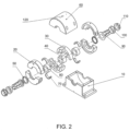
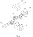
- the present invention provides a smart high performance integrated bearing that combines a fluid film bearing (FFB) with an electro-magnetic actuator (EMA) in one integrated device.
- the fluid film bearing shall carry the load, whereas the electro-magnetic actuator can be used as a pure controller or both as a controller and a load carrying element. In the latter case the electro-magnetic actuator can be considered as an active magnetic bearing (AMB).
- the integrated bearing can have the form of one integral bearing having the fluid film bearing within the magnetic bearing, such that the fluid for the fluid film bearing passes over the rotor of the magnetic bearing, and within the clearance between the rotor and stator in the magnetic bearing.
- fluid film bearings and magnetic bearings are well known devices, yet it is not obvious that they can be used in a combined form, since the current technology is that these are competing devices not complementing devices. Both are considered load carrying devices that have certain control capabilities (passive control for fluid film bearings and active control for magnetic bearings). It is thus an invention to consider the magnetic bearing only as a controlling device, and the fluid film bearing as only a load carrying device. Their combined effect is to have bearings with the advantages of large load carrying capacity, excellent reliability, and use at high speeds without instability, in addition to all the known advantages of fluid film bearings and magnetic bearings. Moreover, an additional advantage will appear, since the magnetic bearing is not used as a load carrying element, the power requirements will be reduced, and thus smaller, lighter magnetic bearings can be used that can control the rotor vibrations reliably.
- the integration of AMBs and JBs in one device, the integrated journal bearing (IJB), has clear advantages.
- the IJB has all of the advantages of JBs and AMBs, and avoids all of the shortcomings of AMBs and JBs.
- the IJB is a superior load carrying element due to its larger load carrying capacity and its ability to introduce passive damping to the rotor system. Moreover, it is free from whip instabilities and has capabilities as a controller.
- An IJB can provide variable and controllable stiffness and damping and additionally can provide unbalance control and many other control features. Most importantly, there is no need for a backup bearing as the rotor is carried on the JB in all cases.
Landscapes
- Engineering & Computer Science (AREA)
- General Engineering & Computer Science (AREA)
- Mechanical Engineering (AREA)
- Chemical & Material Sciences (AREA)
- Oil, Petroleum & Natural Gas (AREA)
- Physics & Mathematics (AREA)
- Electromagnetism (AREA)
- Power Engineering (AREA)
- Magnetic Bearings And Hydrostatic Bearings (AREA)
- Rotary Pumps (AREA)
- Sliding-Contact Bearings (AREA)
Claims (19)
- Integriertes Zapfenlager, IJB, umfassend:eine sich in einer axialen Richtung erstreckende Welle;ein Gehäuse (20), durch das sich die Welle in der axialen Richtung erstreckt, wobei das Gehäuse (20) die Welle in einer radialen Richtung umgibt,einen elektromagnetischen Aktuator, EMA, der in dem Gehäuse (20) angeordnet ist und die Welle in der radialen Richtung umgibt, wobei der EMA Rotorblechpakete (40), die an der Welle angebracht sind, und äußere Lamellenbleche (30), die in dem Gehäuse angeordnet sind, beinhaltet, wobei sich ein radiales EMA-Spiel zwischen den Rotorblechpaketen (40) und den äußeren Lamellenblechen (30) befindet; undmindestens ein erstes Fluidfilm-Zapfenlager, JB, das in dem Gehäuse (20) angeordnet ist und die Welle in der radialen Richtung umgibt, wobei das erste JB eine erste JB-Muffe (80), die an der Welle axial an die Rotorblechpakete (40) angrenzend angebracht ist, und eine erste JB-Auskleidung (70), die in dem Gehäuse (20) angeordnet ist, beinhaltet, wobei sich ein radiales erstes JB-Spiel zwischen der ersten JB-Muffe (80) und der Auskleidung (70) befindet,wobei Fluidleitungen (120) durch das Gehäuse (20) festgelegt und konfiguriert sind, um dem Zapfenlager ein Fluid zuzuführen und das Fluid aus dem Gehäuse (20) abfließen zu lassen,dadurch gekennzeichnet, dassdas Fluid ein Öl ist, das fähig ist, frei zwischen dem EMA und den ersten JB-Spielen und in den Raum des EMA zu fließen, wobei das Öl in dem Gehäuse (20) durch Dichtungen (50) zurückgehalten wird, die zwischen dem Gehäuse (20) und der Welle angeordnet sind.
- IJB nach Anspruch 1, ferner umfassend ein zweites JB, das in dem Gehäuse angeordnet ist und die Welle in der radialen Richtung umgibt, wobei das zweite JB eine zweite JB-Muffe, die an der Welle axial an einer gegenüberliegenden Seite der Rotorblechpakete angrenzend von der ersten JB-Muffe angebracht ist, und eine zweite JB-Auskleidung, die in dem Gehäuse angeordnet ist, beinhaltet, wobei sich ein radiales zweites JB-Spiel zwischen der zweiten JB-Muffe und der Auskleidung befindet, wobei die Ölleitungen ferner konfiguriert sind, um Öl zuzuführen und abfließen zu lassen, das dann frei zwischen dem EMA und den ersten JB-Spielen fließen kann.
- IJB nach Anspruch 2, ferner umfassend eine erste und eine zweite Haltemanschette, die jeweils axial nach außen gerichtet an dem Rotor des ersten und des zweiten JB angebracht sind.
- IJB nach Anspruch 3, ferner umfassend eine erste und eine zweite Dichtung, die an dem Rotor angebracht sind, wobei sich die erste Dichtung axial zwischen dem ersten JB und der ersten Haltemanschette befindet, die zweite Dichtung sich axial zwischen dem zweiten JB und der zweiten Haltemanschette befindet, wobei die erste und die zweite Dichtung konfiguriert sind, um zu verhindern, dass Öl zwischen der Welle und dem Gehäuse entweicht.
- IJB nach Anspruch 3, ferner umfassend einen ersten und einen zweiten Befestigungsadapter, die jeweils die erste und die zweite Haltemanschette umgeben, wobei der erste und der zweite Befestigungsadapter jeweils durch eine erste und eine zweite Feststellmutter arretiert werden.
- IJB nach Anspruch 1, wobei die Welle eine Schulter beinhaltet, die sich in der radialen Richtung nach außen erstreckt, wobei eine Seite der Rotorblechpakete gegenüber der ersten JB-Muffe axial an die Schulter angrenzt.
- IJB nach Anspruch 6, ferner umfassend eine Schelle, die an der Welle axial an eine Seite der ersten JB-Muffe angrenzend gegenüber den Rotorblechpaketen angebracht ist.
- IJB nach Anspruch 6, ferner umfassend eine Haltermanschette, die an der Welle angebracht ist, wobei sich die Haltermanschette radial zwischen der Welle und der ersten JB-Muffe und axial an dieselbe Seite der Rotorblechpakete angrenzend wie die erste JB-Muffe befindet.
- IJB nach Anspruch 8, ferner umfassend eine Feststellmutter, die axial an eine Seite der ersten JB-Muffe angrenzend gegenüber den Rotorblechpaketen mit der Haltermanschette verbunden ist.
- IJB nach Anspruch 1, ferner umfassend einen Controller in Signalverbindung mit dem EMA und konfiguriert, um diesem Strom zuzuführen, um den EMA durch Steuern einer dadurch erzeugten Magnetkraft zu betreiben.
- IJB nach Anspruch 10, wobei der Controller konfiguriert ist, um den EMA zu betreiben, um Lagerlast zusätzlich zu dem JB unter mindestens einigen Wellenbedingungen zu tragen, sodass der EMA als ein aktives Magnetlager (AMB) funktioniert.
- IJB nach Anspruch 11, wobei der Controller konfiguriert ist, um eine Rückmeldung von externen Kräften zu empfangen, die während verschiedener Zustände von diesen auf die Welle angewendet werden, und um die Magnetkraft in Reaktion darauf anzupassen.
- IJB nach Anspruch 12, wobei der Controller konfiguriert ist, um die Magnetkraft zu steuern, die durch das AMB erzeugt wird, sodass das Tragen von Last des ersten JB unter den meisten Umständen nicht beeinträchtigt wird.
- IJB nach Anspruch 13, wobei der Controller konfiguriert ist, um die Magnetkraft zu steuern, die durch das AMB erzeugt wird, sodass es eine variable und steuerbare Steifigkeit und Dämpfung bereitstellt.
- IJB nach Anspruch 13, wobei der Controller konfiguriert ist, um die Magnetkraft zu steuern, die durch das AMB erzeugt wird, sodass es eine Instabilität des JB ausgleicht.
- IJB nach Anspruch 13, wobei der Controller konfiguriert ist, um die Magnetkraft zu steuern, die durch das AMB erzeugt wird, sodass es eine Wellenunwucht ausgleicht.
- IJB nach Anspruch 13, wobei der Controller konfiguriert ist, um die Magnetkraft zu steuern, die durch das AMB erzeugt wird, sodass es auf die Welle wirkende Beeinträchtigungen ausgleicht.
- IJB nach Anspruch 1, wobei der EMA konfiguriert ist, um eine passive Dämpfung bereitzustellen.
- Verfahren zum Unterstützen einer Welle für eine Drehbewegung, wobei das Verfahren umfasst:Unterstützen von radialen Lasten mit mindestens einem ersten Fluidfilm-Zapfenlager, JB, das um die Welle angeordnet ist,Steuern eines aktiven Magnetlagers, AMB, das sich axial an das erst JB auf der Welle angrenzend befindet, um das JB-Lager mindestens unter einigen Bedingungen beim Tragen von radialen Lasten zu unterstützen; undBereitstellen eines gemeinsamen Gehäuses, um das erste JB und das AMB zu umgeben,dadurch gekennzeichnet, dassdas Fluid des ersten JB ein Öl ist, das fähig ist, frei zwischen dem AMB und den ersten JB-Spielen und in den Raum des AMB zu fließen, undDichtungen zum Abdichten zwischen dem Gehäuse und der Welle bereitgestellt werden.
Priority Applications (3)
| Application Number | Priority Date | Filing Date | Title |
|---|---|---|---|
| HRP20241341TT HRP20241341T1 (hr) | 2016-05-17 | 2017-05-17 | Integrirani klizni ležaj |
| EP24179813.1A EP4424437B1 (de) | 2016-05-17 | 2017-05-17 | Integriertes zapfenlager |
| RS20241080A RS66005B1 (sr) | 2016-05-17 | 2017-05-17 | Integrisani klizni ležaj |
Applications Claiming Priority (2)
| Application Number | Priority Date | Filing Date | Title |
|---|---|---|---|
| US201662337555P | 2016-05-17 | 2016-05-17 | |
| PCT/US2017/033077 WO2017201151A1 (en) | 2016-05-17 | 2017-05-17 | Integrated journal bearing |
Related Child Applications (1)
| Application Number | Title | Priority Date | Filing Date |
|---|---|---|---|
| EP24179813.1A Division EP4424437B1 (de) | 2016-05-17 | 2017-05-17 | Integriertes zapfenlager |
Publications (4)
| Publication Number | Publication Date |
|---|---|
| EP3458733A1 EP3458733A1 (de) | 2019-03-27 |
| EP3458733A4 EP3458733A4 (de) | 2019-11-20 |
| EP3458733B1 true EP3458733B1 (de) | 2024-07-03 |
| EP3458733C0 EP3458733C0 (de) | 2024-07-03 |
Family
ID=60325562
Family Applications (2)
| Application Number | Title | Priority Date | Filing Date |
|---|---|---|---|
| EP24179813.1A Active EP4424437B1 (de) | 2016-05-17 | 2017-05-17 | Integriertes zapfenlager |
| EP17800081.6A Active EP3458733B1 (de) | 2016-05-17 | 2017-05-17 | Integriertes zapfenlager |
Family Applications Before (1)
| Application Number | Title | Priority Date | Filing Date |
|---|---|---|---|
| EP24179813.1A Active EP4424437B1 (de) | 2016-05-17 | 2017-05-17 | Integriertes zapfenlager |
Country Status (18)
| Country | Link |
|---|---|
| US (2) | US10612592B2 (de) |
| EP (2) | EP4424437B1 (de) |
| JP (1) | JP7043423B2 (de) |
| KR (1) | KR102377184B1 (de) |
| CN (1) | CN109477511B (de) |
| AU (2) | AU2017268318B2 (de) |
| BR (1) | BR112018073562A2 (de) |
| CA (1) | CA3023958A1 (de) |
| ES (2) | ES3044857T3 (de) |
| HR (2) | HRP20251325T1 (de) |
| HU (1) | HUE068676T2 (de) |
| IL (2) | IL262880B2 (de) |
| MA (1) | MA45049A (de) |
| PL (2) | PL4424437T3 (de) |
| RS (2) | RS66005B1 (de) |
| RU (1) | RU2725842C2 (de) |
| WO (1) | WO2017201151A1 (de) |
| ZA (1) | ZA201808394B (de) |
Families Citing this family (7)
| Publication number | Priority date | Publication date | Assignee | Title |
|---|---|---|---|---|
| HRP20251325T1 (hr) | 2016-05-17 | 2026-02-13 | Aly El-Shafei | Integrirani klizni ležaj |
| CN108547869B (zh) * | 2018-05-18 | 2019-09-10 | 燕山大学 | 一种磁液双悬浮支承轴承系统 |
| US10955000B2 (en) * | 2018-11-09 | 2021-03-23 | Bernabe Segura Candelaria | Bearingless hub assembly with electromagnetic drive system and associated methods |
| US11566663B2 (en) * | 2019-06-26 | 2023-01-31 | Trane International Inc. | Bearing for supporting a rotating compressor shaft |
| US12276228B2 (en) | 2022-07-27 | 2025-04-15 | General Electric Company | Planet gear clearances in epicyclic gearboxes |
| US12516627B2 (en) | 2022-07-27 | 2026-01-06 | General Electric Company | Gas turbine engine |
| US12326172B2 (en) | 2023-04-21 | 2025-06-10 | Rtx Corporation | Magnetic-foil bearing with cooling system |
Citations (1)
| Publication number | Priority date | Publication date | Assignee | Title |
|---|---|---|---|---|
| US4382199A (en) * | 1980-11-06 | 1983-05-03 | Nu-Tech Industries, Inc. | Hydrodynamic bearing system for a brushless DC motor |
Family Cites Families (54)
| Publication number | Priority date | Publication date | Assignee | Title |
|---|---|---|---|---|
| US3969804A (en) | 1973-12-27 | 1976-07-20 | Rajay Industries, Inc. | Bearing housing assembly method for high speed rotating shafts |
| DE2446680C3 (de) | 1974-09-30 | 1980-10-02 | Siemens Ag, 1000 Berlin Und 8000 Muenchen | Tubus zur Begrenzung eines Bündels durchdringender Strahlen |
| SU543786A1 (ru) * | 1975-01-08 | 1977-01-25 | Предприятие П/Я Г-4805 | Комбинированна опора |
| JPS55135225A (en) | 1979-04-06 | 1980-10-21 | Hitachi Ltd | Tilting pad journal bearing |
| EP0068387B1 (de) | 1981-06-29 | 1986-03-26 | Shimadzu Corporation | Fluidfilm-Lager mit Folien |
| US4415281A (en) | 1981-11-23 | 1983-11-15 | United Technologies Corporation | Hydrodynamic fluid film bearing |
| US4488826A (en) * | 1982-09-30 | 1984-12-18 | Federal Mogul Corporation | Offset wall bearing |
| US4597676A (en) | 1984-04-30 | 1986-07-01 | General Electric Company | Hybrid bearing |
| GB2198194B (en) | 1986-12-03 | 1990-05-30 | Nat Res Dev | Improvements in or relating to hydrodynamic journal bearings |
| FR2609123A1 (fr) * | 1986-12-31 | 1988-07-01 | Mecanique Magnetique Sa | Palier fluide hybride a raideur modifiee par effet electromagnetique |
| US4880320A (en) | 1987-03-10 | 1989-11-14 | British Aerospace Plc | Fluid film journal bearings |
| US4828403A (en) | 1987-04-03 | 1989-05-09 | Schwartzman Everett H | Resiliently mounted fluid bearing assembly |
| US4961122A (en) | 1987-05-11 | 1990-10-02 | Hitachi, Ltd. | Hydrodynamic grooved bearing device |
| US5743654A (en) | 1987-05-29 | 1998-04-28 | Kmc, Inc. | Hydrostatic and active control movable pad bearing |
| US5489155A (en) | 1987-05-29 | 1996-02-06 | Ide; Russell D. | Tilt pad variable geometry bearings having tilting bearing pads and methods of making same |
| JPH01269722A (ja) * | 1988-04-22 | 1989-10-27 | Toshiro Higuchi | 磁気制御軸受ユニット |
| FR2636690B1 (fr) | 1988-09-20 | 1992-05-22 | Abg Semca | Palier a film fluide et son procede de realisation |
| US5322371A (en) | 1988-12-23 | 1994-06-21 | Abg Semca Sa | Fluid film bearing |
| JPH02217616A (ja) * | 1989-02-16 | 1990-08-30 | Asahi Optical Co Ltd | 静圧気体軸受 |
| DE69025485T2 (de) | 1989-04-03 | 1996-07-25 | Canon Kk | Hydrodynamische Lagereinrichtung |
| US5098203A (en) | 1991-03-11 | 1992-03-24 | Contraves Goerz Corporation | Bearing system |
| US5201585A (en) | 1991-12-31 | 1993-04-13 | General Electric Company | Fluid film journal bearing with squeeze film damper for turbomachinery |
| JPH05215133A (ja) * | 1992-02-03 | 1993-08-24 | Canon Inc | 静圧流体軸受およびその位置決め制御装置 |
| GB9408485D0 (en) | 1994-04-27 | 1994-06-22 | Martin James K | Fluid film bearings |
| GB2292192B (en) | 1994-08-06 | 1997-12-10 | Glacier Metal Co Ltd | Journal bearings |
| US5456535A (en) | 1994-08-15 | 1995-10-10 | Ingersoll-Rand Company | Journal bearing |
| US5549392A (en) | 1995-05-02 | 1996-08-27 | Nastec, Inc. | Resilient mount pad journal bearing |
| US5531523A (en) | 1995-06-02 | 1996-07-02 | Westinghouse Electric Corporation | Rotor journal bearing having adjustable bearing pads |
| US5634723A (en) | 1995-06-15 | 1997-06-03 | R & D Dynamics Corporation | Hydrodynamic fluid film bearing |
| US5516212A (en) | 1995-09-18 | 1996-05-14 | Western Digital Corporation | Hydrodynamic bearing with controlled lubricant pressure distribution |
| US5795076A (en) | 1995-10-13 | 1998-08-18 | Orion Corporation | Tilt pad hydrodynamic bearing for rotating machinery |
| US5879085A (en) | 1995-10-13 | 1999-03-09 | Orion Corporation | Tilt pad hydrodynamic bearing for rotating machinery |
| JP3305979B2 (ja) | 1997-03-18 | 2002-07-24 | 大同メタル工業株式会社 | すべり軸受 |
| JP2004324895A (ja) | 1997-04-28 | 2004-11-18 | Ntn Corp | 静圧磁気複合軸受 |
| US6353273B1 (en) * | 1997-09-15 | 2002-03-05 | Mohawk Innovative Technology, Inc. | Hybrid foil-magnetic bearing |
| JP2000002469A (ja) * | 1998-06-16 | 2000-01-07 | Mitsubishi Heavy Ind Ltd | 圧縮機及びこれを有する冷凍機 |
| DE19847347C2 (de) | 1998-10-14 | 2001-03-29 | Ldt Gmbh & Co | Magnetlager |
| JP3130890B2 (ja) | 1999-02-25 | 2001-01-31 | セイコー精機株式会社 | 磁気軸受装置及び磁気軸受制御装置 |
| JP3790883B2 (ja) | 2000-01-14 | 2006-06-28 | 株式会社ジェイテクト | 磁気軸受装置 |
| DE10032440A1 (de) | 2000-07-04 | 2002-01-17 | Schlafhorst & Co W | Rotorspinnvorrichtung mit einer berührungslosen passiven radialen Lagerung des Spinnrotors |
| AU2002225701A1 (en) | 2000-11-14 | 2002-05-27 | Airex Corporation | Integrated magnetic bearing |
| US6717311B2 (en) | 2001-06-14 | 2004-04-06 | Mohawk Innovative Technology, Inc. | Combination magnetic radial and thrust bearing |
| TW524929B (en) | 2001-12-24 | 2003-03-21 | Ind Tech Res Inst | Magnetic bearing |
| US6727617B2 (en) | 2002-02-20 | 2004-04-27 | Calnetix | Method and apparatus for providing three axis magnetic bearing having permanent magnets mounted on radial pole stack |
| WO2005122684A2 (en) * | 2004-06-15 | 2005-12-29 | Aly El-Shafei | Methods of controlling the instability in fluid film bearings |
| JP4156604B2 (ja) * | 2005-03-07 | 2008-09-24 | 三菱電機株式会社 | 電磁クラッチ |
| CN1322662C (zh) * | 2005-06-21 | 2007-06-20 | 北京航空航天大学 | 一种集成化、低功耗磁轴承数字控制装置 |
| JP2006062081A (ja) * | 2005-10-07 | 2006-03-09 | Ntn Corp | 金型加工装置 |
| WO2011001290A2 (en) * | 2009-07-02 | 2011-01-06 | Steorn Limited | Passive magnetic bearing |
| DE102010018472A1 (de) * | 2009-07-03 | 2011-01-05 | Schaeffler Technologies Gmbh & Co. Kg | Lager mit Energieerzeugungseinheit |
| JP2014095424A (ja) * | 2012-11-09 | 2014-05-22 | Mitsubishi Heavy Ind Ltd | 磁気予圧式静圧案内装置 |
| US9482282B2 (en) | 2014-08-21 | 2016-11-01 | Zilift Holdings, Ltd. | Bearing for a rotary machine |
| CN204733093U (zh) * | 2015-06-29 | 2015-10-28 | 浙江大学 | 单侧桥臂倍频驱动的三电平开关功率放大器 |
| HRP20251325T1 (hr) | 2016-05-17 | 2026-02-13 | Aly El-Shafei | Integrirani klizni ležaj |
-
2017
- 2017-05-17 HR HRP20251325TT patent/HRP20251325T1/hr unknown
- 2017-05-17 EP EP24179813.1A patent/EP4424437B1/de active Active
- 2017-05-17 CA CA3023958A patent/CA3023958A1/en active Pending
- 2017-05-17 RU RU2018142320A patent/RU2725842C2/ru active
- 2017-05-17 PL PL24179813.1T patent/PL4424437T3/pl unknown
- 2017-05-17 HU HUE17800081A patent/HUE068676T2/hu unknown
- 2017-05-17 MA MA045049A patent/MA45049A/fr unknown
- 2017-05-17 HR HRP20241341TT patent/HRP20241341T1/hr unknown
- 2017-05-17 RS RS20241080A patent/RS66005B1/sr unknown
- 2017-05-17 RS RS20251063A patent/RS67342B1/sr unknown
- 2017-05-17 US US15/597,628 patent/US10612592B2/en active Active
- 2017-05-17 IL IL262880A patent/IL262880B2/en unknown
- 2017-05-17 BR BR112018073562-0A patent/BR112018073562A2/pt active IP Right Grant
- 2017-05-17 ES ES24179813T patent/ES3044857T3/es active Active
- 2017-05-17 AU AU2017268318A patent/AU2017268318B2/en active Active
- 2017-05-17 PL PL17800081.6T patent/PL3458733T3/pl unknown
- 2017-05-17 ES ES17800081T patent/ES2988150T3/es active Active
- 2017-05-17 EP EP17800081.6A patent/EP3458733B1/de active Active
- 2017-05-17 KR KR1020187036438A patent/KR102377184B1/ko active Active
- 2017-05-17 JP JP2018559756A patent/JP7043423B2/ja active Active
- 2017-05-17 WO PCT/US2017/033077 patent/WO2017201151A1/en not_active Ceased
- 2017-05-17 CN CN201780043844.6A patent/CN109477511B/zh active Active
- 2017-05-17 IL IL300968A patent/IL300968B2/en unknown
-
2018
- 2018-12-12 ZA ZA2018/08394A patent/ZA201808394B/en unknown
-
2019
- 2019-04-05 US US16/376,503 patent/US10954999B2/en active Active
-
2021
- 2021-06-11 AU AU2021203888A patent/AU2021203888B2/en active Active
Patent Citations (1)
| Publication number | Priority date | Publication date | Assignee | Title |
|---|---|---|---|---|
| US4382199A (en) * | 1980-11-06 | 1983-05-03 | Nu-Tech Industries, Inc. | Hydrodynamic bearing system for a brushless DC motor |
Also Published As
Similar Documents
| Publication | Publication Date | Title |
|---|---|---|
| AU2021203888B2 (en) | Integrated journal bearing | |
| US6747383B2 (en) | Generator with hydraulically mounted stator rotor | |
| US20140125176A1 (en) | Hybrid Bearing | |
| JPS61262222A (ja) | 軸受支持体 | |
| EP1350035B1 (de) | Fluidfilmlager mit flexibler folie und wirbelstromdämpfer | |
| JPS58149415A (ja) | 制振軸受 | |
| El-Shafei | Semajib: A versatile high performance smart bearing | |
| Swanson et al. | A test stand for dynamic characterization of oil-free bearings for modern gas turbine engines | |
| US3365248A (en) | Magnetic bearing loading | |
| Holmes et al. | Large-amplitude vibrations in rotor assemblies | |
| Swanson et al. | Performance of a foil-magnetic hybrid bearing | |
| CN121139440A (zh) | 一种矢量磁控磁流变轴承支承的透平压缩机及控制方法 | |
| Roberts | The multiple attractions of magnetic bearings | |
| ROTOR | Copyright© 1984 by ASME | |
| JPH03249422A (ja) | 回転機械の防振支持構造 |
Legal Events
| Date | Code | Title | Description |
|---|---|---|---|
| STAA | Information on the status of an ep patent application or granted ep patent |
Free format text: STATUS: THE INTERNATIONAL PUBLICATION HAS BEEN MADE |
|
| PUAI | Public reference made under article 153(3) epc to a published international application that has entered the european phase |
Free format text: ORIGINAL CODE: 0009012 |
|
| STAA | Information on the status of an ep patent application or granted ep patent |
Free format text: STATUS: REQUEST FOR EXAMINATION WAS MADE |
|
| 17P | Request for examination filed |
Effective date: 20181214 |
|
| AK | Designated contracting states |
Kind code of ref document: A1 Designated state(s): AL AT BE BG CH CY CZ DE DK EE ES FI FR GB GR HR HU IE IS IT LI LT LU LV MC MK MT NL NO PL PT RO RS SE SI SK SM TR |
|
| AX | Request for extension of the european patent |
Extension state: BA ME |
|
| RAV | Requested validation state of the european patent: fee paid |
Extension state: MA Effective date: 20181214 |
|
| A4 | Supplementary search report drawn up and despatched |
Effective date: 20191022 |
|
| RIC1 | Information provided on ipc code assigned before grant |
Ipc: F16C 33/10 20060101ALI20191016BHEP Ipc: F16C 32/04 20060101ALI20191016BHEP Ipc: B21K 1/76 20060101ALI20191016BHEP Ipc: F16C 17/02 20060101AFI20191016BHEP Ipc: H02K 7/08 20060101ALI20191016BHEP Ipc: F16C 17/24 20060101ALI20191016BHEP |
|
| STAA | Information on the status of an ep patent application or granted ep patent |
Free format text: STATUS: EXAMINATION IS IN PROGRESS |
|
| 17Q | First examination report despatched |
Effective date: 20201110 |
|
| GRAP | Despatch of communication of intention to grant a patent |
Free format text: ORIGINAL CODE: EPIDOSNIGR1 |
|
| STAA | Information on the status of an ep patent application or granted ep patent |
Free format text: STATUS: GRANT OF PATENT IS INTENDED |
|
| INTG | Intention to grant announced |
Effective date: 20240131 |
|
| GRAS | Grant fee paid |
Free format text: ORIGINAL CODE: EPIDOSNIGR3 |
|
| GRAA | (expected) grant |
Free format text: ORIGINAL CODE: 0009210 |
|
| STAA | Information on the status of an ep patent application or granted ep patent |
Free format text: STATUS: THE PATENT HAS BEEN GRANTED |
|
| AK | Designated contracting states |
Kind code of ref document: B1 Designated state(s): AL AT BE BG CH CY CZ DE DK EE ES FI FR GB GR HR HU IE IS IT LI LT LU LV MC MK MT NL NO PL PT RO RS SE SI SK SM TR |
|
| REG | Reference to a national code |
Ref country code: CH Ref legal event code: EP |
|
| REG | Reference to a national code |
Ref country code: DE Ref legal event code: R096 Ref document number: 602017083027 Country of ref document: DE |
|
| U01 | Request for unitary effect filed |
Effective date: 20240718 |
|
| U07 | Unitary effect registered |
Designated state(s): AT BE BG DE DK EE FI FR IT LT LU LV MT NL PT SE SI Effective date: 20240801 |
|
| REG | Reference to a national code |
Ref country code: ES Ref legal event code: FG2A Ref document number: 2988150 Country of ref document: ES Kind code of ref document: T3 Effective date: 20241119 |
|
| REG | Reference to a national code |
Ref country code: SK Ref legal event code: T3 Ref document number: E 45051 Country of ref document: SK |
|
| REG | Reference to a national code |
Ref country code: GR Ref legal event code: EP Ref document number: 20240402299 Country of ref document: GR Effective date: 20241111 |
|
| PG25 | Lapsed in a contracting state [announced via postgrant information from national office to epo] |
Ref country code: IS Free format text: LAPSE BECAUSE OF FAILURE TO SUBMIT A TRANSLATION OF THE DESCRIPTION OR TO PAY THE FEE WITHIN THE PRESCRIBED TIME-LIMIT Effective date: 20241103 |
|
| REG | Reference to a national code |
Ref country code: HU Ref legal event code: AG4A Ref document number: E068676 Country of ref document: HU |
|
| PG25 | Lapsed in a contracting state [announced via postgrant information from national office to epo] |
Ref country code: IS Free format text: LAPSE BECAUSE OF FAILURE TO SUBMIT A TRANSLATION OF THE DESCRIPTION OR TO PAY THE FEE WITHIN THE PRESCRIBED TIME-LIMIT Effective date: 20241103 |
|
| U1N | Appointed representative for the unitary patent procedure changed after the registration of the unitary effect |
Representative=s name: HARRISON IP LIMITED; GB |
|
| PG25 | Lapsed in a contracting state [announced via postgrant information from national office to epo] |
Ref country code: SM Free format text: LAPSE BECAUSE OF FAILURE TO SUBMIT A TRANSLATION OF THE DESCRIPTION OR TO PAY THE FEE WITHIN THE PRESCRIBED TIME-LIMIT Effective date: 20240703 |
|
| PLBE | No opposition filed within time limit |
Free format text: ORIGINAL CODE: 0009261 |
|
| STAA | Information on the status of an ep patent application or granted ep patent |
Free format text: STATUS: NO OPPOSITION FILED WITHIN TIME LIMIT |
|
| REG | Reference to a national code |
Ref country code: HR Ref legal event code: ODRP Ref document number: P20241341T Country of ref document: HR Payment date: 20250507 Year of fee payment: 9 |
|
| U20 | Renewal fee for the european patent with unitary effect paid |
Year of fee payment: 9 Effective date: 20250501 |
|
| 26N | No opposition filed |
Effective date: 20250404 |
|
| PGFP | Annual fee paid to national office [announced via postgrant information from national office to epo] |
Ref country code: PL Payment date: 20250502 Year of fee payment: 9 |
|
| PGFP | Annual fee paid to national office [announced via postgrant information from national office to epo] |
Ref country code: GB Payment date: 20250501 Year of fee payment: 9 Ref country code: ES Payment date: 20250611 Year of fee payment: 9 |
|
| PGFP | Annual fee paid to national office [announced via postgrant information from national office to epo] |
Ref country code: RS Payment date: 20250507 Year of fee payment: 9 Ref country code: HU Payment date: 20250507 Year of fee payment: 9 Ref country code: NO Payment date: 20250520 Year of fee payment: 9 |
|
| PGFP | Annual fee paid to national office [announced via postgrant information from national office to epo] |
Ref country code: HR Payment date: 20250507 Year of fee payment: 9 |
|
| PGFP | Annual fee paid to national office [announced via postgrant information from national office to epo] |
Ref country code: GR Payment date: 20250501 Year of fee payment: 9 |
|
| PGFP | Annual fee paid to national office [announced via postgrant information from national office to epo] |
Ref country code: CH Payment date: 20250625 Year of fee payment: 9 |
|
| PGFP | Annual fee paid to national office [announced via postgrant information from national office to epo] |
Ref country code: TR Payment date: 20250502 Year of fee payment: 9 Ref country code: SK Payment date: 20250505 Year of fee payment: 9 |
|
| PGFP | Annual fee paid to national office [announced via postgrant information from national office to epo] |
Ref country code: CZ Payment date: 20250502 Year of fee payment: 9 |
|
| PGFP | Annual fee paid to national office [announced via postgrant information from national office to epo] |
Ref country code: IE Payment date: 20250519 Year of fee payment: 9 |
|
| REG | Reference to a national code |
Ref country code: HR Ref legal event code: T1PR Ref document number: P20241341 Country of ref document: HR |
|
| PG25 | Lapsed in a contracting state [announced via postgrant information from national office to epo] |
Ref country code: MC Free format text: LAPSE BECAUSE OF FAILURE TO SUBMIT A TRANSLATION OF THE DESCRIPTION OR TO PAY THE FEE WITHIN THE PRESCRIBED TIME-LIMIT Effective date: 20240703 |
|
| VS25 | Lapsed in a validation state [announced via postgrant information from nat. office to epo] |
Ref country code: MA Free format text: FAILURE TO ELECT DOMICILE IN THE NATIONAL COUNTRY Effective date: 20241004 |