EP3456583A1 - Armlehne - Google Patents
Armlehne Download PDFInfo
- Publication number
- EP3456583A1 EP3456583A1 EP18193613.9A EP18193613A EP3456583A1 EP 3456583 A1 EP3456583 A1 EP 3456583A1 EP 18193613 A EP18193613 A EP 18193613A EP 3456583 A1 EP3456583 A1 EP 3456583A1
- Authority
- EP
- European Patent Office
- Prior art keywords
- armrest
- guide means
- guide
- base
- rod
- Prior art date
- Legal status (The legal status is an assumption and is not a legal conclusion. Google has not performed a legal analysis and makes no representation as to the accuracy of the status listed.)
- Granted
Links
Images




Classifications
-
- B—PERFORMING OPERATIONS; TRANSPORTING
- B60—VEHICLES IN GENERAL
- B60N—SEATS SPECIALLY ADAPTED FOR VEHICLES; VEHICLE PASSENGER ACCOMMODATION NOT OTHERWISE PROVIDED FOR
- B60N2/00—Seats specially adapted for vehicles; Arrangement or mounting of seats in vehicles
- B60N2/75—Arm-rests
- B60N2/753—Arm-rests movable to an inoperative position
-
- A—HUMAN NECESSITIES
- A47—FURNITURE; DOMESTIC ARTICLES OR APPLIANCES; COFFEE MILLS; SPICE MILLS; SUCTION CLEANERS IN GENERAL
- A47C—CHAIRS; SOFAS; BEDS
- A47C7/00—Parts, details, or accessories of chairs or stools
- A47C7/54—Supports for the arms
- A47C7/541—Supports for the arms of adjustable type
-
- B—PERFORMING OPERATIONS; TRANSPORTING
- B60—VEHICLES IN GENERAL
- B60N—SEATS SPECIALLY ADAPTED FOR VEHICLES; VEHICLE PASSENGER ACCOMMODATION NOT OTHERWISE PROVIDED FOR
- B60N2/00—Seats specially adapted for vehicles; Arrangement or mounting of seats in vehicles
- B60N2/75—Arm-rests
- B60N2/763—Arm-rests adjustable
-
- B—PERFORMING OPERATIONS; TRANSPORTING
- B60—VEHICLES IN GENERAL
- B60N—SEATS SPECIALLY ADAPTED FOR VEHICLES; VEHICLE PASSENGER ACCOMMODATION NOT OTHERWISE PROVIDED FOR
- B60N2/00—Seats specially adapted for vehicles; Arrangement or mounting of seats in vehicles
- B60N2/75—Arm-rests
- B60N2/763—Arm-rests adjustable
- B60N2/767—Angle adjustment
-
- B—PERFORMING OPERATIONS; TRANSPORTING
- B60—VEHICLES IN GENERAL
- B60N—SEATS SPECIALLY ADAPTED FOR VEHICLES; VEHICLE PASSENGER ACCOMMODATION NOT OTHERWISE PROVIDED FOR
- B60N2/00—Seats specially adapted for vehicles; Arrangement or mounting of seats in vehicles
- B60N2/75—Arm-rests
- B60N2/763—Arm-rests adjustable
- B60N2/773—Longitudinal adjustment
-
- B—PERFORMING OPERATIONS; TRANSPORTING
- B60—VEHICLES IN GENERAL
- B60N—SEATS SPECIALLY ADAPTED FOR VEHICLES; VEHICLE PASSENGER ACCOMMODATION NOT OTHERWISE PROVIDED FOR
- B60N3/00—Arrangements or adaptations of other passenger fittings, not otherwise provided for
- B60N3/02—Arrangements or adaptations of other passenger fittings, not otherwise provided for of hand grips or straps
- B60N3/026—Arrangements or adaptations of other passenger fittings, not otherwise provided for of hand grips or straps characterised by the fixing means
-
- B—PERFORMING OPERATIONS; TRANSPORTING
- B60—VEHICLES IN GENERAL
- B60N—SEATS SPECIALLY ADAPTED FOR VEHICLES; VEHICLE PASSENGER ACCOMMODATION NOT OTHERWISE PROVIDED FOR
- B60N2205/00—General mechanical or structural details
- B60N2205/20—Measures for elimination or compensation of play or backlash
Definitions
- the invention relates to an armrest.
- Such an armrest is for example from the DE 10 2007 013 081 known.
- An armrest of the armrest is movably guided on guide tubes between a first position and a second position. In this way, the position of the armrest can be adjusted according to the needs of the seat occupant.
- the armrest includes a base and a relative to the base between a first position, a second position in opposite displacement directions along a trajectory sliding armrest.
- the armrest is movable in any intermediate positions between the first position and the second position.
- the armrest is translationally displaceable along the path of movement.
- the movement path may be straight or curved or at least have a straight and at least one curved section.
- the armrest comprises a guide device comprising first guide means associated with the base and second guide means associated with the armrest.
- the first guide means are e.g. attached directly or indirectly to the base or integrally formed therewith.
- the second guide means are e.g. attached to the armrest directly or indirectly or integrally formed therewith.
- the first guide means and the second guide means form cooperating guide surfaces which are movable relative to each other.
- the guide means limit the movement of the armrest in at least one direction, which is directed at right angles to the direction of displacement.
- the guide device comprises an elastic member which holds the first guide means in contact with the second guide means, even when the armrest is relieved.
- contact is not exclusively the direct contact, but also an indirect stop of the cooperating guide means.
- the elastic member loads the first guide means or the second guide means in a first loading direction relative to the respective other guide means, as the relative position of the first guide means to the second guide means at a defined Load corresponds.
- this is, for example, a stress situation in which the armrest is loaded downwards because a seat occupant is supported on it.
- the elastic member biases the cooperating guide means into a relative position as would be due to the jacking load imposed by a seat occupant. In the actual load case then no relative movement of the armrest occurs to the base in this load direction.
- the game is less disturbing, since the armrest is damped by the elastic member.
- the load is usually lower, so that the elastic element also prevents or dampens a game.
- the play in such a load can also be influenced by the elastic element is designed stiffer or less stiff.
- the elastic element may e.g. itself may be elastically deformable or it may e.g. be burdened by a spring.
- the elastic element may e.g. from a plastic, e.g. from a plastic foam, be formed.
- the cooperating guide surfaces are substantially non-deformable.
- the guide surfaces are formed for example of a rigid plastic, a metal or a composite material.
- Undeformable in the sense of the invention means that the guide surfaces do not deform or only insignificantly deform during a load that usually occurs.
- the first guide means and / or the second guide means comprise at least one bearing component which can be fastened directly or indirectly to the base or to the armrest.
- the bearing member limits the movement of the armrest in at least one direction at right angles to the direction of displacement.
- the bearing component may e.g. limit the movement of the armrest in two directions at right angles to the displacement direction.
- the bearing component is e.g. formed substantially undeformable.
- the bearing component is e.g. formed by a rigid plastic or a metal.
- the bearing component may be a sliding bearing, a ball bearing or a roller bearing.
- the elastic element is e.g. assigned to the bearing component. It can e.g. be attached to the bearing component.
- the bearing member is mounted in this way together with the elastic member in a simple manner according to the loading position of the cooperating guide means.
- the bearing component is e.g. designed as a ring.
- the ring encloses e.g. a rod of the guide means at least partially.
- the ring need not be closed, it may be an open ring, which partially surrounds the rod.
- the ring may also completely enclose the rod according to an alternative embodiment.
- the first guide means or the second guide means comprise at least one pair of spaced bearing members. For example, if the armrest is loaded outside the space between the two bearing components, a tilting moment may occur around one of the two bearing components. Each of the two bearing components is then loaded in opposite directions.
- the cooperating guide means comprise e.g. a rod which forms a guide with at least one receptacle.
- the rod is e.g. guided on the recording or recording is performed on the rod.
- the rod is translationally displaceable relative to the receptacle.
- the rod may e.g. be formed of plastic, a metal or a composite material.
- the rod is e.g. assigned to the armrest and the inclusion of the base. According to an alternative, the rod is e.g. assigned to the base and the inclusion of the armrest.
- the rod is e.g. attached to the armrest or to the base or integrally formed therewith.
- the shot is e.g. attached to the base or on the armrest or integrally formed therewith.
- the guiding device comprises e.g. two bars.
- the rods act e.g. with at least one recording together.
- the rods are e.g. arranged in parallel.
- a longitudinal axis of the rods is e.g. directed in the direction of displacement.
- Each rod acts e.g. with at least one bearing component together.
- Each bearing component can be arranged in a separate receptacle.
- two bearing components which interact with a rod arranged in a receptacle.
- each rod e.g. guided each rod in two bearing components, wherein four bearing components are arranged in a receptacle.
- the receptacle may be assigned to the base or the armrest.
- the rod is, for example cylindrical, in particular circular cylindrical and formed the receptacle complementary. This allows for easy production and ensures a jam-free guidance.
- the armrest is e.g. pivotable about a pivot axis between a primary position and a secondary position.
- the primary position is e.g. an approximately horizontal use position and the secondary position an approximately vertical non-use position.
- An armrest as a whole is designated by the reference numeral 10 in the figures.
- Like reference numerals in the various figures indicate corresponding parts, even if small letters are readjusted or omitted.
- the armrest 10 comprises according to a first, in the Fig. 1 to 7 and 9 to 16 illustrated embodiment, a base 11 and an armrest 12 with a support surface 13. On the support surface 13, the user can support.
- the armrest 12 is movable relative to the base 11 in the directions x1 and x2.
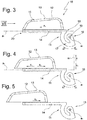
- Fig. 1 and 3 is the armrest 12 in a rear position, in Fig. 4 in a middle position and in the Fig. 2 and 5 shown in a forward position.
- the middle position corresponds to an intermediate position. In this way, the position of the armrest 12 can be optimally adapted to the seat occupant.
- the base 11 is formed by a vehicle-fixed pivot axis a 1 and by a pivotable about the pivot axis a arm 14, so that the armrest 12 is pivotally about the pivot axis a1 in pivot directions u1 and u2.
- Fig. 3 illustrated position in which a longitudinal axis a2 of the armrest 12 is arranged approximately horizontally, the armrest can be pivoted in the direction u1 in a position, not shown, in which the longitudinal axis a2 is arranged approximately vertically.
- This position is in Fig. 4 indicated by a dashed line a 2 ', which is formed parallel to the directions z1 and z2.
- a pivot joint may be formed, for example, between a socket, not shown, and the arm 14.
- a swivel-axis-side region 16 of the arm 14 forms an extension 17 which bears against a bearing region 18 is provided with openings 19 for engaging bearing means.
- the arm 14 also defines a free end 20.
- Fig. 6 shows the armrest 10, wherein a housing 15 of the armrest 12 is not shown.
- the arm 14 is fixedly connected to a receptacle 21, in which two recesses 22a and 22b are formed in the form of linear bores.
- the recess 22a is of a rod 23a and the recess 22b is penetrated by a rod 23b.
- the rods 23 a and 23 b are firmly held on the armrest 12.
- a longitudinal central axis of the recesses 22a and 22b and a longitudinal center axis of the rods 23a and 23b are aligned parallel to a longitudinal axis a2 of the armrest.
- the rods 23a and 23b move relative to the receptacle 21 in the recesses 22a and 22b.
- the rods 23a and 23b and the recesses 22a and 22b are formed circular cylindrical. Alternatively, they can have a different shape.
- Fig. 8 an armrest from the prior art.
- the armrest 12 was according to the prior art Fig. 8 firmly connected to two annular bearings La and Lb. These consisted of an elastically deformable material. When loaded with a force F, it deforms until the rods 23a and 23b engage the soffits of the recesses 22a and 22b. That took the user of the armrest as a clear match. Since the center of gravity of the force F is in the usual load situation in the direction x1 in front of the bearing La, the armrest 12 tilts relative to the receptacle 21 in the play of the rods 23a and 23b in the recesses 22a and 22b in the direction v.
- the armrest 10 on the end of the recess 22b bearing seats, which are each provided with an annular bearing 24, which serves as a sliding bearing for the rods 23a and 23b.
- annular bearing 24 which serves as a sliding bearing for the rods 23a and 23b.
- the rod 23a is supported by means of the bearings 24 arranged in the bearing seats 25a and 25b and the rod 23b by means of the bearings 24 arranged in the bearing seats 25c and 25d.
- the bearings 24 limit movement of each rod 23a and 23b in a YZ plane resulting from the directional arrows y1 and y2 and z1 and z2.
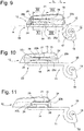
- the rods 23a and 23b contact a soffit 27 of each bearing 24. Due to the tilting of the armrest 12, the rods 23a and 23b are located at the bearing seats 25a and 25c on a lower surface 28 (see Figs FIGS. 12 and 13 ) and at the bearing seats 25b and 25d at an upper side 29 of the recesses 22a and 22b and the bearing 24 at.
- Each bearing 24 is formed, for example, as a closed or open ring and provided with an elastic element 26.
- the ring is formed for example by a relatively stiff plastic.
- the elastic member 26 is formed only on a peripheral portion of the bearing 24. In this way, the elastic element 26 loads the rods 23a and 23b against the elastic element 26 diametrically opposite side of the soffit 27, in particular the soffit 27 of the ring. As in the FIGS.
- Fig. 14 shows the assembly of the receptacle 21 and the bearings 24.
- Fig. 15 the bearings 21 are in the same arrangement as in FIG Fig. 14 shown, wherein the receptacle 21 is not shown for clarity.
- Fig. 16 the first embodiment is shown again as a schematic diagram.
- the elastic members 26 load the rod 23b according to the loading direction by a force F corresponding to the main load situation by supporting an arm of the user, with the armrest being tilted in the direction v.
- the bearing 24 of the bearing 25c is loaded in the direction z2 and the bearing 24 of the bearing 25d in the direction z1.
- Fig. 16 a schematic diagram of a second embodiment of the arm 10 is shown, which differs from the first embodiment only in that the receptacle 21 fixed to the armrest 12 and the rods 23a and 23b are fixedly connected to the arm 14.
- the rods 23a and 23b are deformed by the elastic members 26 of the bearings 15a and 25c in the direction z1 and by the elastic members 26 of the bearings 15b and 15d in FIG Direction z2 loaded, which corresponds to the load situation under the action of a force F.
Landscapes
- Engineering & Computer Science (AREA)
- Transportation (AREA)
- Mechanical Engineering (AREA)
- Aviation & Aerospace Engineering (AREA)
- Seats For Vehicles (AREA)
- Steps, Ramps, And Handrails (AREA)
Abstract
Description
- Die Erfindung betrifft eine Armlehne.
- Eine solche Armlehne ist z.B. aus der
DE 10 2007 013 081 bekannt. Eine Armauflage der Armlehne ist zwischen einer ersten Position und einer zweiten Position bewegbar an Führungsrohren geführt. Auf diese Weise kann die Position der Armauflage nach den Bedürfnissen des Sitzinsassen eingestellt werden. - Bei solchen Armlehnen aus dem Stand der Technik war es üblich jedes Führungsrohr in zwei Gleitlagern zu führen, wobei die Gleitlager von elastisch verformbaren Kunststoffringen, insbesondere z.B. von Ringen aus dem Material Cellasto® der BASF, gebildet waren. Aufgrund der elastischen Verformbarkeit gaben diese Ringe bei einer Belastung nach, bis das Führungsrohr an dem steifen Aufnahmeelement zur Anlage kam, in welchem der Ring angeordnet war. Die Verlagerung der Armauflage infolge der elastischen Verformung des Ringes nahm der Benutzer als deutliches Spiel wahr. In den Endlagen kann dieses Spiel durch Auffahrrampen beseitigt werden. In Zwischenpositionen, ist das - insbesondere wenn die Armlehne nicht verriegelbar ist - nicht möglich und für den Benutzer daher besonders störend.
- Es war Aufgabe der Erfindung eine Armlehne mit einer zwischen einer ersten Position und einer zweiten Position verlagerbaren Armauflage zu schaffen, die bei einer Belastung annähernd spielfrei ist.
- Die Aufgabe wurde gelöst durch eine Armlehne mit den Merkmalen des Anspruchs 1.
- Die Armlehne umfasst eine Basis und eine relativ zu der Basis zwischen einer ersten Position, einer zweiten Position in entgegengesetzte Verschieberichtungen entlang einer Bewegungsbahn verschiebbaren Armauflage. Dabei ist die Armauflage auch in beliebige Zwischenpositionen zwischen der ersten Position und der zweiten Position bewegbar. Die Armauflage ist translatorisch entlang der Bewegungsbahn verschiebbar. Die Bewegungsbahn kann gerade oder gekrümmt ausgebildet sein oder wenigstens einen geraden und wenigstens einen gekrümmten Abschnitt aufweisen.
- Die Armlehne umfasst eine Führungsvorrichtung aufweisend der Basis zugeordnete erste Führungsmittel und der Armauflage zugeordnete zweite Führungsmittel. Die ersten Führungsmittel sind z.B. an der Basis unmittelbar oder mittelbar befestigt oder einteilig damit ausgebildet. Die zweiten Führungsmittel sind z.B. an der Armauflage unmittelbar oder mittelbar befestigt oder einteilig damit ausgebildet. Die ersten Führungsmittel und die zweiten Führungsmittel bilden zusammenwirkende Führungsflächen aus, die relativ zueinander bewegbar sind. Die Führungsmittel begrenzen die Bewegung der Armauflage in wenigstens eine Richtung, die rechtwinklig zu der Verschieberichtung gerichtet ist.
- Zwischen den Führungsmitteln ist ein Spiel ausgebildet. Wenn eine Kraft F auf die Armlauflage einwirkt, stehen Führungsflächen der ersten Führungsmittel und der zweiten Führungsmittel in Kontakt. Die Führungsvorrichtung umfasst ein elastisches Element, welches die ersten Führungsmittel in Kontakt mit den zweiten Führungsmittel hält, auch wenn die Armauflage entlastet wird. Mit Kontakt ist im Sinne der Erfindung nicht ausschließlich der unmittelbare Kontakt zu verstehen, sondern auch ein mittelbarer Anschlag der zusammenwirkenden Führungsmittel.
- Das elastische Element belastet die ersten Führungsmittel oder die zweiten Führungsmittel derart in eine erste Belastungs-Richtung relativ zu den jeweils anderen Führungsmitteln, wie es der Relativposition der ersten Führungsmittel zu den zweiten Führungsmittel bei einer definierten Belastung entspricht. Bei der Armauflage ist das z.B. eine Belastungssituation, bei welcher die Armauflage nach unten belastet wird, weil sich ein Sitzinsasse darauf abstützt. Mit anderen Worten, das elastische Element belastet die zusammenwirkenden Führungsmittel in eine Relativposition, wie sie sich aufgrund der Abstütz-Belastung durch einen Sitzinsassen einstellen würde. Im tatsächlichen Belastungsfall tritt dann keine Relativbewegung der Armauflage zu der Basis in diese Belastungs-Richtung auf.
- Bei einer Belastung in eine zweite Belastungs-Richtung, die der ersten Belastungs-Richtung entgegengesetzt gerichtet ist, wie z.B. beim Schwenken der Armauflage aus einer Position, bei welcher eine Längsmittelachse etwa horizontal ausgerichtet ist, in eine etwa vertikale Ausrichtung, ist das Spiel weniger störend, da die Armauflage von dem elastischen Element gedämpft wird. Darüber hinaus ist die Belastung in der Regel geringer, so dass das elastische Element ein Spiel ebenfalls verhindert oder dieses dämpft. Das Spiel bei einer solchen Belastung kann zudem beeinflusst werden, indem das elastische Element steifer oder weniger steif ausgelegt wird.
- Das elastische Element kann z.B. selbst elastisch verformbar sein oder es kann z.B. von einer Feder belastet sein. Das elastische Element kann z.B. von einem Kunststoff, z.B. von einem Kunststoffschaum, gebildet sein.
- Die zusammenwirkenden Führungsflächen, sind im Wesentlichen unverformbar ausgebildet. Die Führungsflächen sind z.B. von einem steifen Kunststoff, einem Metall oder einem Verbundwerkstoff gebildet. Unverformbar bedeutet im Sinne der Erfindung, dass sich die Führungsflächen bei einer üblicherweise stattfindenden Belastung nicht oder lediglich unwesentlich verformen.
- Die ersten Führungsmittel und / oder die zweiten Führungsmittel umfassen wenigstens ein Lagerbauteil, welches unmittelbar oder mittelbar an der Basis oder an der Armauflage befestigbar ist. Das Lagerbauteil begrenzt die Bewegung der Armauflage in wenigstens eine rechtwinklig zur Verschieberichtung angeordnete Richtung. Das Lagerbauteil kann z.B. die Bewegung der Armauflage in zwei zu der Verschieberichtung rechtwinklig gerichtete Raumrichtungen begrenzen.
- Das Lagerbauteil ist z.B. im Wesentlichen unverformbar ausgebildet. Das Lagerbauteil ist z.B. von einem steifen Kunststoff oder einem Metall gebildet. Bei dem Lagerbauteil kann es sich um ein Gleitlager, ein Kugellager oder ein Rollenlager handeln.
- Das elastische Element ist z.B. dem Lagerbauteil zugeordnet. Es kann z.B. an dem Lagerbauteil befestigt sein. Das Lagerbauteil ist auf diese Weise zusammen mit dem elastischen Element auf einfache Weise entsprechend der Belastungsposition der zusammenwirkenden Führungsmittel montierbar.
- Das Lagerbauteil ist z.B. als Ring ausgebildet. Der Ring umschließt z.B. eine Stange der Führungsmittel wenigstens teilweise. Mit anderen Worten muss der Ring nicht geschlossen sein, es kann sich um einen offenen Ring handeln, welcher die Stange teilweise umschließt. Der Ring kann die Stange gemäß einer alternativen Ausführung auch vollständig umschließen.
- Z.B. umfassen die ersten Führungsmittel oder die zweiten Führungsmittel wenigstens ein Paar beabstandeter Lagerbauteile. Wenn die Armauflage z.B. außerhalb des Zwischenraums zwischen den beiden Lagerbauteilen belastet wird, kann z.B. ein Kippmoment um eines der beiden Lagerbauteile auftreten. Jedes der beiden Lagerbauteile wird dann in entgegengesetzte Richtungen belastet.
- Die zusammenwirkenden Führungsmittel umfassen z.B. eine Stange, die mit wenigstens einer Aufnahme eine Führung bildet. Die Stange ist z.B. an der Aufnahme geführt oder die Aufnahme ist an der Stange geführt. Die Stange ist relativ zu der Aufnahme translatorisch verschiebbar. Die Stange kann z.B. aus Kunststoff, einem Metall oder einem Verbundwerkstoff gebildet sein.
- Die Stange ist z.B. der Armauflage und die Aufnahme der Basis zugeordnet. Gemäß einer Alternative ist die Stange z.B. der Basis und die Aufnahme der Armauflage zugeordnet. Die Stange ist z.B. an der Armauflage oder an der Basis befestigt oder einteilig damit ausgebildet. Die Aufnahme ist z.B. an der Basis oder an der Armauflage befestigt oder einteilig damit ausgebildet.
- Die Führungsvorrichtung umfasst z.B. zwei Stangen. Die Stangen wirken z.B. mit wenigstens einer Aufnahme zusammen. Die Stangen sind z.B. parallel angeordnet. Eine Längsachse der Stangen ist z.B. in Verschieberichtung gerichtet. Jede Stange wirkt z.B. mit wenigstens einem Lagerbauteil zusammen.
- Jedes Lagerbauteil kann in einer separaten Aufnahme angeordnet sein. Alternativ sind z.B. je zwei Lagerbauteile, die mit einer Stange zusammenwirken in einer Aufnahme angeordnet. Gemäß einer weiteren Alternative ist z.B. jede Stange in zwei Lagerbauteilen geführt, wobei vier Lagerbauteile in einer Aufnahme angeordnet sind. Die Aufnahme kann der Basis oder der Armauflage zugeordnet sein.
- Die Stange ist z.B. zylindrisch, insbesondere kreiszylindrisch und die Aufnahme komplementär ausgebildet. Das ermöglicht eine einfache Fertigung und gewährleistet eine klemmfreie Führung.
- Die Armauflage ist z.B. um eine Schwenkachse zwischen einer primären Position und einer sekundären Position schwenkbar. Die primäre Position ist z.B. eine etwa horizontale Gebrauchsposition und die sekundäre Position eine etwa vertikale Nichtgebrauchsposition.
- Weitere Vorteile der Erfindung ergeben sich anhand der Beschreibung von in den Fig. schematisch dargestellten Ausführungsbeispielen. Es zeigen:
-
Fig. 1 eine perspektivische Ansicht einer Armlehne von vorne, wobei sich eine Armauflage der Armlehne in einer hinteren Position befindet, -
Fig. 2 die Armlehne gemäßFig. 1 , wobei die Armauflage in eine vordere Position verlagert ist, -
Fig. 3 eine Seitenansicht der Armlehne, wobei die Armauflage in der hinteren Position angeordnet ist, -
Fig. 4 eine Seitenansicht der Armlehne, wobei die Armauflage in einer Zwischenposition angeordnet ist, -
Fig. 5 eine Seitenansicht der Armlehne, wobei die Armauflage in der vorderen Position angeordnet ist, -
Fig. 6 eine perspektivische Darstellung der Armlehne von vorne, gemäßFig. 1 , wobei ein Gehäuse der Armauflage nicht dargestellt ist, -
Fig. 7 eine Frontdarstellung der Armlehne gemäß Ansichtspfeil VII inFig. 3 , -
Fig. 8 eine Längsschnittdarstellung einer Armlehne aus dem Stand der Technik, -
Fig. 9 eine Längsschnittdarstellung der erfindungsgemäßen Armlehne gemäß Schnittlinie IX - IX inFig. 7 , -
Fig. 10 die Armlehne gemäßFig. 9 , wobei die Armauflage in der Zwischenposition angeordnet ist und wobei die Schraffur der Übersichtlichkeit halber nicht dargestellt ist, -
Fig. 11 die Armlehne gemäßFig. 9 , wobei die Armauflage in der vorderen Position angeordnet ist und wobei die Schraffur der Übersichtlichkeit halber nicht dargestellt ist, -
Fig. 12 eine Schnittdarstellung gemäß Schnittlinie XII - XII inFig. 9 , wobei die Schraffur der geschnittenen Flächen der Übersichtlichkeit halber nicht dargestellt ist, -
Fig. 13 eine Schnittdarstellung gemäß Schnittlinie XIII - XIII inFig. 9 , wobei die Schraffur der geschnittenen Flächen der Übersichtlichkeit halber nicht dargestellt ist, -
Fig. 14 perspektivische Einzelteildarstellung der Aufnahme einschließlich der Lager von vorne, -
Fig. 15 in Anlehnung anFig. 14 die Anordnung der Lager, wobei die Aufnahme 21 nicht dargestellt ist, -
Fig. 16 eine Prinzipskizze der Armlehne gemäß dem ersten Ausführungsbeispiel in Längsschnittdarstellung, -
Fig. 17 eine derFig. 16 entsprechende Prinzipskizze einer alternativen Ausführungsform der Armlehne in Längsschnittdarstellung, wobei die Schraffur der Übersichtlichkeit halber nicht dargestellt ist. - Eine Armlehne insgesamt ist in den Fig. mit dem Bezugszeichen 10 bezeichnet. Gleiche Bezugszeichen in den unterschiedlichen Fig. bezeichnen entsprechende Teile, auch wenn kleine Buchstaben nachgestellt oder weggelassen sind.
- Die Armlehne 10 umfasst gemäß einem ersten, in den
Fig. 1 bis 7 und9 bis 16 dargestellten Ausführungsbeispiel eine Basis 11 sowie eine Armauflage 12 mit einer Auflagefläche 13. Auf der Auflagefläche 13 kann sich der Benutzer abstützen. Die Armauflage 12 ist relativ zu der Basis 11 in die Richtungen x1 und x2 bewegbar. In denFig. 1 und3 ist die Armauflage 12 in einer hinteren Position, inFig. 4 in einer mittleren Position und in denFig. 2 und5 in einer vorderen Position dargestellt. Die mittlere Position entspricht einer Zwischenposition. Auf diese Weise kann die Position der Armauflage 12 optimal an den Sitzinsassen angepasst werden. - Im vorliegenden Ausführungsbeispiel ist die Basis 11 von einer fahrzeugfesten Schwenkachse a1 sowie von einem um die Schwenkachse a schwenkbaren Arm 14 gebildet, so dass die Armauflage 12 um die Schwenkachse a1 in Schwenkrichtungen u1 und u2 schwenkbar ausgebildet ist. Aus einer in
Fig. 3 dargestellten Position, in welcher eine Längsachse a2 der Armauflage 12 etwa horizontal angeordnet ist, kann die Armauflage in Richtung u1 in eine nicht dargestellte Position geschwenkt werden, in welcher die Längsachse a2 etwa vertikal angeordnet ist. Diese Position ist inFig. 4 durch eine Strichpunktlinie a2' angedeutet, die parallel zu den Richtungen z1 und z2 ausgebildet ist. - Ein Schwenkgelenk kann z.B. zwischen einem nicht dargestellten Sockel und dem Arm 14 gebildet sein. Ein schwenkachsenseitiger Bereich 16 des Arms 14 bildet einen Fortsatz 17, der an einem Lagerbereich 18 mit Öffnungen 19 zum Eingreifen von Lagermitteln versehen ist. Der Arm 14 bildet darüber hinaus ein freies Ende 20 aus.
-
Fig. 6 zeigt die Armlehne 10, wobei ein Gehäuse 15 der Armauflage 12 nicht dargestellt ist. Der Arm 14 ist fest mit einer Aufnahme 21 verbunden, in welcher zwei Aussparungen 22a und 22b in Form linearer Bohrungen ausgebildet sind. Die Aussparung 22a ist von einer Stange 23a und die Aussparung 22b ist von einer Stange 23b durchgriffen. Die Stangen 23a und 23b sind fest an der Armauflage 12 gehalten. Eine Längsmittelachse der Aussparungen 22a und 22b sowie eine Längsmittelachse der Stangen 23a und 23b sind parallel zu einer Längsachse a2 der Armlehne ausgerichtet. - Bei einer Bewegung der Armauflage 12 in eine der Richtungen x1 oder x2 bewegen sich die Stangen 23a und 23b relativ zu der Aufnahme 21 in den Aussparungen 22a und 22b. Im vorliegenden Ausführungsbeispiel sind die Stangen 23a und 23b und die Aussparungen 22a und 22b kreiszylindrisch ausgebildet. Sie können alternativ aber auch eine andere Form besitzen.
- In
Fig. 8 ist eine Armlehne aus dem Stand der Technik dargestellt. Die Armauflage 12 war im Stand der Technik gemäßFig. 8 fest mit zwei ringförmigen Lagern La und Lb verbunden. Diese bestanden aus einem elastisch verformbaren Material. Bei einer Belastung mit einer Kraft F verformte sich dieses, bis die Stangen 23a und 23b an der Laibung der Aussparungen 22a und 22b anschlugen. Das nahm der Benutzer der Armlehne als deutliches Spiel war. Da der Schwerpunkt der Kraft F in der üblichen Belastungssituation in Richtung x1 vor dem Lager La liegt, kippt die Armauflage 12 relativ zu der Aufnahme 21 im Rahmen des Spiels der Stangen 23a und 23b in den Aussparungen 22a und 22b in Richtung v. - Entsprechend der Aufgabe der Erfindung sollte dieses Spiel vermieden werden.
- Wie in den
Fig. 9 ,12 und 13 zu erkennen ist, weist die erfindungsgemäße Armlehne 10 endseitig der Aussparung 22b Lagersitze auf, die jeweils mit einem ringförmigen Lager 24 versehen sind, welches als Gleitlagerung für die Stangen 23a und 23b dient. Aus den Schnittdarstellungen gemäß derFig. 12 und 13 ist ersichtlich, dass insgesamt vier Lagersitze 25a, 25b, 25c und 25d in der Aufnahme 21 ausgebildet sind. Die Stange 23a ist mittels der in den Lagersitzen 25a und 25b angeordneten Lager 24 und die Stange 23b mittels der in den Lagersitzen 25c und 25d angeordneten Lager 24 gelagert. Die Lager 24 begrenzen eine Bewegung jeder Stange 23a und 23b in einer Y-Z-Ebene, welche sich aus den Richtungspfeilen y1 und y2 sowie z1 und z2 ergibt. - Bei einer Belastung der Armauflage 12 mit einer Kraft F, was der Hauptbelastungssituation durch Abstützen des Arms eines Benutzers entspricht, liegen die Stangen 23a und 23b an einer Laibung 27 jedes Lagers 24 an. Aufgrund des Kippens der Armauflage 12 liegen die Stangen 23a und 23b bei den Lagersitzen 25a und 25c an einer Unterseite 28 (siehe die
Fig. 12 und 13 ) und bei den Lagersitzen 25b und 25d an einer Oberseite 29 der Aussparungen 22a und 22b bzw. der Lager 24 an. - Jedes Lager 24 ist z.B. als geschlossener oder offener Ring ausgebildet und mit einem elastischen Element 26 versehen. Der Ring ist z.B. von einem relativ steifen Kunststoff gebildet. Das elastische Element 26 ist lediglich an einem Umfangsteilbereich des Lagers 24 ausgebildet. Auf diese Weise belastet das elastische Element 26 die Stangen 23a und 23b gegen die dem elastischen Element 26 diametral gegenüberliegende Seite der Laibung 27, insbesondere der Laibung 27 des Rings. Wie in den
Fig. 12 und 13 zu erkennen, sind die Lager 24 derart relativ zu der Aufnahme 21 angeordnet, dass die Stangen 23a und 23b von dem elastischen Element 26 der Lagerstellen 25a und 25c in Richtung z2 und von dem elastischen Element 26 der Lagerstellen 25b und 25d in Richtung z1 belastet werden, was der Relativposition von den Stangen 23a und 23b zu der Aufnahme 21 im Falle des Aufbringens einer Kraft F auf die Armauflage 12, insbesondere auf die Auflagefläche 13, entspricht. - Damit verbleibt die Armauflage 12 nach Wegnahme der Kraft F in derselben Position relativ zu der Aufnahme 21. Der Benutzer kann bei Be- bzw. Entlastung der Armauflage 12 kein Spiel feststellen.
-
Fig. 14 zeigt die Baugruppe aus der Aufnahme 21 und den Lagern 24. InFig. 15 sind die Lager 21 in der gleichen Anordnung wie inFig. 14 dargestellt, wobei die Aufnahme 21 der Übersichtlichkeit halber nicht dargestellt ist. - In
Fig. 16 ist das erste Ausführungsbeispiel noch einmal als Prinzipskizze dargestellt. Die elastischen Elemente 26 belasten die Stange 23b entsprechend der Belastungsrichtung durch eine Kraft F, die der Hauptbelastungssituation durch Aufstützen eines Arms des Benutzers entspricht, wobei die Armauflage in Richtung v gekippt wird. Das Lager 24 der Lagerstelle 25c wird in Richtung z2 und das Lager 24 der Lagerstelle 25d in Richtung z1 belastet. - In
Fig. 16 ist eine Prinzipskizze eines zweiten Ausführungsbeispiels der Armlehne 10 dargestellt, welches sich lediglich dadurch von dem ersten Ausführungsbeispiel unterscheidet, dass die Aufnahme 21 fest mit der Armauflage 12 und die Stangen 23a und 23b fest mit dem Arm 14 verbunden sind. In diesem Fall werden die Stangen 23a und 23b von den elastischen Elementen 26 der Lagerstellen 15a und 25c in Richtung z1 und von den elastischen Elementen 26 der Lagerstellen 15b und 15d in Richtung z2 belastet, was der Belastungssituation unter Einwirkung einer Kraft F entspricht.
Claims (10)
- Armlehne mit einer Basis (11) und mit einer Armauflage (12), welche relativ zu der Basis (11) über Zwischenpositionen zwischen einer ersten Position und einer zweiten Position in entgegengesetzte Verschieberichtungen (x1, x2) entlang einer Bewegungsbahn translatorisch verschiebbar ist, mit einer Führungsvorrichtung umfassend der Basis (11) zugeordnete erste Führungsmittel und der Armauflage (12) zugeordnete zweite Führungsmittel, die zusammenwirkende, relativ zueinander bewegbare Führungsflächen ausbilden, welche die Bewegung der Armauflage (12) relativ zu der Basis (11) in wenigstens eine Richtung rechtwinklig zur Verschieberichtung begrenzen, wobei zwischen den ersten Führungsmitteln und den zweiten Führungsmitteln ein Spiel ausgebildet ist und wobei im Falle einer Belastung mit einer auf die Armauflage einwirkenden Kraft (F) Führungsflächen der ersten Führungsmittel und der zweiten Führungsmittel in Kontakt stehen, dadurch gekennzeichnet, dass die Führungsvorrichtung wenigstens ein elastisches Element (26) umfasst, welches die ersten Führungsmittel derart in Anlage an die zweiten Führungsmittel belastet, dass bei einer Entlastung der Kontakt erhalten bleibt.
- Armlehne nach Anspruch 1, dadurch gekennzeichnet, dass die zusammenwirkenden Führungsflächen im Wesentlichen unverformbar ausgebildet ist.
- Armlehne nach einem der vorangehenden Ansprüche, dadurch gekennzeichnet, dass die ersten Führungsmittel oder die zweiten Führungsmittel wenigstens ein an der Basis (11) und / oder an der Armauflage (12) befestigbares Lagerbauteil (24) umfassen.
- Armlehne nach Anspruch 3, dadurch gekennzeichnet, dass das elastische Element (26) dem Lagerbauteil (24) zugeordnet ist.
- Armlehne nach Anspruch 3 oder 4, dadurch gekennzeichnet, dass das Lagerbauteil (24) als Ring ausgebildet ist.
- Armlehne nach einem der Ansprüche 3 bis 5, dadurch gekennzeichnet, dass die ersten Führungsmittel oder die zweiten Führungsmittel wenigstens ein Paar beabstandeter Lagerbauteile (24) umfasst.
- Armlehne nach einem der vorangehenden Ansprüche, dadurch gekennzeichnet, dass die zusammenwirkenden Führungsmittel wenigstens eine Stange (23a, 23b) umfassen, die mit wenigstens einer Aufnahme (21) eine Führung bildet.
- Armlehne nach Anspruch 7, dadurch gekennzeichnet, dass die Stange (23a, 23b) der Armauflage (12) und die Aufnahme (21) der Basis (11) zugeordnet ist oder dass die Stange (23a, 23b) der Armauflage (12) und die Aufnahme (21) der Basis (11) zugeordnet ist.
- Armlehne nach einem der Ansprüche 7 oder 8, dadurch gekennzeichnet, dass die Führungsvorrichtung zwei Stangen (23a, 23b) umfasst, die mit wenigstens einer Aufnahme (21) zusammenwirkt.
- Armlehne nach einem der Ansprüche 7 bis 9, dadurch gekennzeichnet, dass die Stange zylindrisch, insbesondere kreiszylindrisch, und die Aufnahme komplementär ausgebildet ist.
Applications Claiming Priority (1)
| Application Number | Priority Date | Filing Date | Title |
|---|---|---|---|
| DE102017121255.8A DE102017121255A1 (de) | 2017-09-13 | 2017-09-13 | Armlehne |
Publications (2)
| Publication Number | Publication Date |
|---|---|
| EP3456583A1 true EP3456583A1 (de) | 2019-03-20 |
| EP3456583B1 EP3456583B1 (de) | 2020-11-04 |
Family
ID=63557265
Family Applications (1)
| Application Number | Title | Priority Date | Filing Date |
|---|---|---|---|
| EP18193613.9A Active EP3456583B1 (de) | 2017-09-13 | 2018-09-11 | Armlehne |
Country Status (4)
| Country | Link |
|---|---|
| US (1) | US11058225B2 (de) |
| EP (1) | EP3456583B1 (de) |
| CN (1) | CN109484266B (de) |
| DE (1) | DE102017121255A1 (de) |
Families Citing this family (6)
| Publication number | Priority date | Publication date | Assignee | Title |
|---|---|---|---|---|
| CN110641335A (zh) * | 2019-11-06 | 2020-01-03 | 华晨鑫源重庆汽车有限公司 | 一种便于前后调节的中控扶手 |
| DE102019130254B4 (de) * | 2019-11-08 | 2022-02-03 | Grammer Aktiengesellschaft | Fahrzeugausstattungvorrichtung |
| FR3109120B1 (fr) * | 2020-04-08 | 2022-04-22 | Faurecia Interieur Ind | Ensemble d’aménagement intérieur de véhicule avec dispositif de verrouillage |
| FR3109121B1 (fr) * | 2020-04-08 | 2022-04-22 | Faurecia Interieur Ind | Ensemble d’aménagement intérieur de véhicule |
| US11285849B2 (en) * | 2020-05-29 | 2022-03-29 | Lear Corporation | Vehicle seat and armrest assembly with free play minimization mechanism |
| CN114954178B (zh) * | 2022-07-06 | 2024-01-30 | 浙江吉利控股集团有限公司 | 一种汽车副仪表扶手及汽车 |
Citations (5)
| Publication number | Priority date | Publication date | Assignee | Title |
|---|---|---|---|---|
| DE10126536A1 (de) * | 2001-05-30 | 2002-12-12 | Grammer Ag | Armlehne für einen Fahrzeugsitz |
| EP1400401A2 (de) * | 2002-09-23 | 2004-03-24 | Seeber AG & Co. KG | Auf einem Träger abgestützter Deckel |
| DE102007013081A1 (de) | 2007-03-14 | 2008-09-18 | Grammer Ag | Armlehne, insbesondere für Kraftfahrzeuge |
| WO2010002261A1 (en) * | 2008-07-04 | 2010-01-07 | Thomas Regout International B.V. | Sliding guide and arm support provided with such a sliding guide |
| DE102014220049A1 (de) * | 2014-10-02 | 2016-04-07 | Schock Metallwerk Gmbh | Führungsvorrichtung |
Family Cites Families (20)
| Publication number | Priority date | Publication date | Assignee | Title |
|---|---|---|---|---|
| US5281001A (en) * | 1991-09-05 | 1994-01-25 | Bergsten Jeffrey D | Ergonomic arm support |
| US6022079A (en) * | 1991-09-05 | 2000-02-08 | Industrial Ergonomics | Ergonomic arm support |
| US6203109B1 (en) * | 1991-09-05 | 2001-03-20 | Industrial Ergonomics, Inc. | Ergonomic arm support |
| US5369805A (en) * | 1991-09-05 | 1994-12-06 | Bergsten; Jeffrey D. | Ergonomic arm support |
| US5884974A (en) * | 1991-09-05 | 1999-03-23 | Industrial Ergonomics | Ergonomic arm support and bracket |
| US6142570A (en) * | 1991-09-05 | 2000-11-07 | Industrial Ergonomics, Inc. | Ergonomic arm support |
| US5597207A (en) * | 1991-09-05 | 1997-01-28 | Industrial Ergonomics | Ergonomic arm support |
| US5851054A (en) * | 1991-09-05 | 1998-12-22 | Industrial Ergonomics, Inc. | Ergonomic arm support |
| US6419314B1 (en) * | 2001-01-05 | 2002-07-16 | Johnson Controls Technology Company | Vehicle accessory with sliding cover |
| DE202005005988U1 (de) * | 2005-04-13 | 2005-07-14 | Bock 1 Gmbh & Co. Kg | Armlehne, insbesondere für einen Bürostuhl |
| ATE533379T1 (de) * | 2005-08-11 | 2011-12-15 | Accuride Int Ltd | Verbesserungen bei oder in bezug auf gleitstützen |
| US20070262632A1 (en) * | 2006-01-18 | 2007-11-15 | Collins & Aikman Products Co. | Sliding Armrest |
| JP4914304B2 (ja) * | 2007-07-30 | 2012-04-11 | ダイキョーニシカワ株式会社 | コンソールボックス |
| JP4480036B2 (ja) * | 2007-09-10 | 2010-06-16 | 森六テクノロジー株式会社 | アームレストの取付け構造 |
| DE102010036000B4 (de) * | 2010-08-31 | 2014-11-27 | F.S. Fehrer Automotive Gmbh | Mittelkonsole mit Linearführung |
| DE102014005620B4 (de) * | 2014-04-16 | 2016-11-03 | Grammer Ag | Staubunempfindliche Gleitschiene |
| CN107176068A (zh) * | 2016-03-09 | 2017-09-19 | 福特环球技术公司 | 用于车辆中控台的滑动机构及车辆中控台滑动扶手总成 |
| DE102017102429B4 (de) * | 2017-02-08 | 2023-01-05 | Lisa Dräxlmaier GmbH | Armlehne für ein Kraftfahrzeug |
| IT201700036472A1 (it) * | 2017-04-03 | 2018-10-03 | Brado S P A | Dispositivo di traslazione assiale di braccioli, in particolare per sedie da ufficio |
| DE102017206720B4 (de) * | 2017-04-21 | 2022-02-24 | Ford Global Technologies, Llc | Fahrzeugkonsole mit einer verstellbaren Armauflage |
-
2017
- 2017-09-13 DE DE102017121255.8A patent/DE102017121255A1/de active Pending
-
2018
- 2018-09-11 EP EP18193613.9A patent/EP3456583B1/de active Active
- 2018-09-12 US US16/129,018 patent/US11058225B2/en active Active
- 2018-09-13 CN CN201811066865.2A patent/CN109484266B/zh active Active
Patent Citations (5)
| Publication number | Priority date | Publication date | Assignee | Title |
|---|---|---|---|---|
| DE10126536A1 (de) * | 2001-05-30 | 2002-12-12 | Grammer Ag | Armlehne für einen Fahrzeugsitz |
| EP1400401A2 (de) * | 2002-09-23 | 2004-03-24 | Seeber AG & Co. KG | Auf einem Träger abgestützter Deckel |
| DE102007013081A1 (de) | 2007-03-14 | 2008-09-18 | Grammer Ag | Armlehne, insbesondere für Kraftfahrzeuge |
| WO2010002261A1 (en) * | 2008-07-04 | 2010-01-07 | Thomas Regout International B.V. | Sliding guide and arm support provided with such a sliding guide |
| DE102014220049A1 (de) * | 2014-10-02 | 2016-04-07 | Schock Metallwerk Gmbh | Führungsvorrichtung |
Also Published As
| Publication number | Publication date |
|---|---|
| DE102017121255A1 (de) | 2019-03-14 |
| EP3456583B1 (de) | 2020-11-04 |
| US20190082851A1 (en) | 2019-03-21 |
| CN109484266B (zh) | 2025-05-27 |
| US11058225B2 (en) | 2021-07-13 |
| CN109484266A (zh) | 2019-03-19 |
Similar Documents
| Publication | Publication Date | Title |
|---|---|---|
| EP3456583B1 (de) | Armlehne | |
| EP3045347B1 (de) | Lagervorrichtung und kopfstütze | |
| DE102015011477B4 (de) | Kopfstütze | |
| EP2818360B1 (de) | Fahrzeugsitz und nutzkraftfahrzeug mit wenigstens einem fahrzeugsitz | |
| DE2426573C2 (de) | Zweibeinstütze für Schußwaffen | |
| DE202006000491U1 (de) | Permanentkontaktmechanik | |
| WO2012027762A1 (de) | Lenksäule für ein kraftfahrzeug | |
| EP0198056B1 (de) | Sitzträger für stühle, insbesondere arbeitsdrehstühle | |
| EP2983943A1 (de) | Längseinsteller für einen fahrzeugsitz und fahrzeugsitz | |
| EP2387913B1 (de) | Vorrichtung zur Verbesserung der menschlichen Sitzhaltung | |
| DE102014001980B3 (de) | Kopfstütze für Fahrzeugsitze | |
| EP3590760B1 (de) | Kopfstütze | |
| EP3838669A1 (de) | Sperrbalken zur anordnung in einem laderaum eines fahrzeugs | |
| DE202021100671U1 (de) | Kopfstütze | |
| EP3392078B1 (de) | Gelenkvorrichtung, ausstattungsvorrichtung eines fahrzeuginnenraums umfassend eine gelenkvorrichtung sowie ein verfahren zur montage der gelenkvorrichtung | |
| EP3406482B1 (de) | Kopfstütze und verfahren zur montage einer kopfstütze | |
| EP3059117B1 (de) | Kopfstütze | |
| EP3819513B1 (de) | Geitlager, ausstattungsvorrichtung mit wenigstens einem gleitlager und ausstattungsvorrichtung mit wenigstens einem drehbaren aufgenommenen lager | |
| DE19819502C2 (de) | Anordnung zur stufenlosen Verstellung einer Kopfstütze an einer Sitzlehne eines Sitzes für Kraftfahrzeuge | |
| DE102019006162B4 (de) | Betätigungsvorrichtung zur Betätigung einer Ausstattungsvorrichtung des Fahrzeuginnenraums und ein Fahrzeugausstattungsteil | |
| DE102008011620A1 (de) | Verstellbare Lenksäule für ein Kraftfahrzeug | |
| DE602005002970T2 (de) | Axialer Wegbegrenzer für das Druckstück einer Kraftfahrzeug-Zahnstangenlenkung | |
| EP3636106B1 (de) | Sitzmöbel mit begrenzbarer und/oder blockierbarer bewegungsmöglichkeit | |
| EP2319370B1 (de) | Sitzvorrichtung | |
| EP3964387B1 (de) | Federelement und fahrzeugsitz mit federelement |
Legal Events
| Date | Code | Title | Description |
|---|---|---|---|
| PUAI | Public reference made under article 153(3) epc to a published international application that has entered the european phase |
Free format text: ORIGINAL CODE: 0009012 |
|
| STAA | Information on the status of an ep patent application or granted ep patent |
Free format text: STATUS: THE APPLICATION HAS BEEN PUBLISHED |
|
| AK | Designated contracting states |
Kind code of ref document: A1 Designated state(s): AL AT BE BG CH CY CZ DE DK EE ES FI FR GB GR HR HU IE IS IT LI LT LU LV MC MK MT NL NO PL PT RO RS SE SI SK SM TR |
|
| AX | Request for extension of the european patent |
Extension state: BA ME |
|
| STAA | Information on the status of an ep patent application or granted ep patent |
Free format text: STATUS: REQUEST FOR EXAMINATION WAS MADE |
|
| 17P | Request for examination filed |
Effective date: 20190430 |
|
| RBV | Designated contracting states (corrected) |
Designated state(s): AL AT BE BG CH CY CZ DE DK EE ES FI FR GB GR HR HU IE IS IT LI LT LU LV MC MK MT NL NO PL PT RO RS SE SI SK SM TR |
|
| GRAP | Despatch of communication of intention to grant a patent |
Free format text: ORIGINAL CODE: EPIDOSNIGR1 |
|
| STAA | Information on the status of an ep patent application or granted ep patent |
Free format text: STATUS: GRANT OF PATENT IS INTENDED |
|
| INTG | Intention to grant announced |
Effective date: 20200519 |
|
| GRAS | Grant fee paid |
Free format text: ORIGINAL CODE: EPIDOSNIGR3 |
|
| GRAA | (expected) grant |
Free format text: ORIGINAL CODE: 0009210 |
|
| STAA | Information on the status of an ep patent application or granted ep patent |
Free format text: STATUS: THE PATENT HAS BEEN GRANTED |
|
| AK | Designated contracting states |
Kind code of ref document: B1 Designated state(s): AL AT BE BG CH CY CZ DE DK EE ES FI FR GB GR HR HU IE IS IT LI LT LU LV MC MK MT NL NO PL PT RO RS SE SI SK SM TR |
|
| REG | Reference to a national code |
Ref country code: GB Ref legal event code: FG4D Free format text: NOT ENGLISH |
|
| REG | Reference to a national code |
Ref country code: CH Ref legal event code: EP |
|
| REG | Reference to a national code |
Ref country code: AT Ref legal event code: REF Ref document number: 1330410 Country of ref document: AT Kind code of ref document: T Effective date: 20201115 |
|
| REG | Reference to a national code |
Ref country code: DE Ref legal event code: R096 Ref document number: 502018002904 Country of ref document: DE |
|
| REG | Reference to a national code |
Ref country code: IE Ref legal event code: FG4D Free format text: LANGUAGE OF EP DOCUMENT: GERMAN |
|
| RAP2 | Party data changed (patent owner data changed or rights of a patent transferred) |
Owner name: GRAMMER AG |
|
| REG | Reference to a national code |
Ref country code: NL Ref legal event code: MP Effective date: 20201104 |
|
| PG25 | Lapsed in a contracting state [announced via postgrant information from national office to epo] |
Ref country code: PT Free format text: LAPSE BECAUSE OF FAILURE TO SUBMIT A TRANSLATION OF THE DESCRIPTION OR TO PAY THE FEE WITHIN THE PRESCRIBED TIME-LIMIT Effective date: 20210304 Ref country code: RS Free format text: LAPSE BECAUSE OF FAILURE TO SUBMIT A TRANSLATION OF THE DESCRIPTION OR TO PAY THE FEE WITHIN THE PRESCRIBED TIME-LIMIT Effective date: 20201104 Ref country code: FI Free format text: LAPSE BECAUSE OF FAILURE TO SUBMIT A TRANSLATION OF THE DESCRIPTION OR TO PAY THE FEE WITHIN THE PRESCRIBED TIME-LIMIT Effective date: 20201104 Ref country code: NO Free format text: LAPSE BECAUSE OF FAILURE TO SUBMIT A TRANSLATION OF THE DESCRIPTION OR TO PAY THE FEE WITHIN THE PRESCRIBED TIME-LIMIT Effective date: 20210204 Ref country code: GR Free format text: LAPSE BECAUSE OF FAILURE TO SUBMIT A TRANSLATION OF THE DESCRIPTION OR TO PAY THE FEE WITHIN THE PRESCRIBED TIME-LIMIT Effective date: 20210205 |
|
| PG25 | Lapsed in a contracting state [announced via postgrant information from national office to epo] |
Ref country code: ES Free format text: LAPSE BECAUSE OF FAILURE TO SUBMIT A TRANSLATION OF THE DESCRIPTION OR TO PAY THE FEE WITHIN THE PRESCRIBED TIME-LIMIT Effective date: 20201104 Ref country code: SE Free format text: LAPSE BECAUSE OF FAILURE TO SUBMIT A TRANSLATION OF THE DESCRIPTION OR TO PAY THE FEE WITHIN THE PRESCRIBED TIME-LIMIT Effective date: 20201104 Ref country code: LV Free format text: LAPSE BECAUSE OF FAILURE TO SUBMIT A TRANSLATION OF THE DESCRIPTION OR TO PAY THE FEE WITHIN THE PRESCRIBED TIME-LIMIT Effective date: 20201104 Ref country code: IS Free format text: LAPSE BECAUSE OF FAILURE TO SUBMIT A TRANSLATION OF THE DESCRIPTION OR TO PAY THE FEE WITHIN THE PRESCRIBED TIME-LIMIT Effective date: 20210304 Ref country code: PL Free format text: LAPSE BECAUSE OF FAILURE TO SUBMIT A TRANSLATION OF THE DESCRIPTION OR TO PAY THE FEE WITHIN THE PRESCRIBED TIME-LIMIT Effective date: 20201104 Ref country code: BG Free format text: LAPSE BECAUSE OF FAILURE TO SUBMIT A TRANSLATION OF THE DESCRIPTION OR TO PAY THE FEE WITHIN THE PRESCRIBED TIME-LIMIT Effective date: 20210204 |
|
| REG | Reference to a national code |
Ref country code: LT Ref legal event code: MG9D |
|
| PG25 | Lapsed in a contracting state [announced via postgrant information from national office to epo] |
Ref country code: HR Free format text: LAPSE BECAUSE OF FAILURE TO SUBMIT A TRANSLATION OF THE DESCRIPTION OR TO PAY THE FEE WITHIN THE PRESCRIBED TIME-LIMIT Effective date: 20201104 |
|
| PG25 | Lapsed in a contracting state [announced via postgrant information from national office to epo] |
Ref country code: SM Free format text: LAPSE BECAUSE OF FAILURE TO SUBMIT A TRANSLATION OF THE DESCRIPTION OR TO PAY THE FEE WITHIN THE PRESCRIBED TIME-LIMIT Effective date: 20201104 Ref country code: CZ Free format text: LAPSE BECAUSE OF FAILURE TO SUBMIT A TRANSLATION OF THE DESCRIPTION OR TO PAY THE FEE WITHIN THE PRESCRIBED TIME-LIMIT Effective date: 20201104 Ref country code: EE Free format text: LAPSE BECAUSE OF FAILURE TO SUBMIT A TRANSLATION OF THE DESCRIPTION OR TO PAY THE FEE WITHIN THE PRESCRIBED TIME-LIMIT Effective date: 20201104 Ref country code: LT Free format text: LAPSE BECAUSE OF FAILURE TO SUBMIT A TRANSLATION OF THE DESCRIPTION OR TO PAY THE FEE WITHIN THE PRESCRIBED TIME-LIMIT Effective date: 20201104 Ref country code: RO Free format text: LAPSE BECAUSE OF FAILURE TO SUBMIT A TRANSLATION OF THE DESCRIPTION OR TO PAY THE FEE WITHIN THE PRESCRIBED TIME-LIMIT Effective date: 20201104 Ref country code: SK Free format text: LAPSE BECAUSE OF FAILURE TO SUBMIT A TRANSLATION OF THE DESCRIPTION OR TO PAY THE FEE WITHIN THE PRESCRIBED TIME-LIMIT Effective date: 20201104 |
|
| REG | Reference to a national code |
Ref country code: DE Ref legal event code: R097 Ref document number: 502018002904 Country of ref document: DE |
|
| PG25 | Lapsed in a contracting state [announced via postgrant information from national office to epo] |
Ref country code: DK Free format text: LAPSE BECAUSE OF FAILURE TO SUBMIT A TRANSLATION OF THE DESCRIPTION OR TO PAY THE FEE WITHIN THE PRESCRIBED TIME-LIMIT Effective date: 20201104 |
|
| PLBE | No opposition filed within time limit |
Free format text: ORIGINAL CODE: 0009261 |
|
| STAA | Information on the status of an ep patent application or granted ep patent |
Free format text: STATUS: NO OPPOSITION FILED WITHIN TIME LIMIT |
|
| 26N | No opposition filed |
Effective date: 20210805 |
|
| PG25 | Lapsed in a contracting state [announced via postgrant information from national office to epo] |
Ref country code: AL Free format text: LAPSE BECAUSE OF FAILURE TO SUBMIT A TRANSLATION OF THE DESCRIPTION OR TO PAY THE FEE WITHIN THE PRESCRIBED TIME-LIMIT Effective date: 20201104 Ref country code: NL Free format text: LAPSE BECAUSE OF FAILURE TO SUBMIT A TRANSLATION OF THE DESCRIPTION OR TO PAY THE FEE WITHIN THE PRESCRIBED TIME-LIMIT Effective date: 20201104 |
|
| PG25 | Lapsed in a contracting state [announced via postgrant information from national office to epo] |
Ref country code: SI Free format text: LAPSE BECAUSE OF FAILURE TO SUBMIT A TRANSLATION OF THE DESCRIPTION OR TO PAY THE FEE WITHIN THE PRESCRIBED TIME-LIMIT Effective date: 20201104 |
|
| REG | Reference to a national code |
Ref country code: CH Ref legal event code: PL |
|
| REG | Reference to a national code |
Ref country code: BE Ref legal event code: MM Effective date: 20210930 |
|
| PG25 | Lapsed in a contracting state [announced via postgrant information from national office to epo] |
Ref country code: IS Free format text: LAPSE BECAUSE OF FAILURE TO SUBMIT A TRANSLATION OF THE DESCRIPTION OR TO PAY THE FEE WITHIN THE PRESCRIBED TIME-LIMIT Effective date: 20210304 Ref country code: MC Free format text: LAPSE BECAUSE OF FAILURE TO SUBMIT A TRANSLATION OF THE DESCRIPTION OR TO PAY THE FEE WITHIN THE PRESCRIBED TIME-LIMIT Effective date: 20201104 |
|
| PG25 | Lapsed in a contracting state [announced via postgrant information from national office to epo] |
Ref country code: LU Free format text: LAPSE BECAUSE OF NON-PAYMENT OF DUE FEES Effective date: 20210911 Ref country code: IE Free format text: LAPSE BECAUSE OF NON-PAYMENT OF DUE FEES Effective date: 20210911 Ref country code: BE Free format text: LAPSE BECAUSE OF NON-PAYMENT OF DUE FEES Effective date: 20210930 |
|
| PG25 | Lapsed in a contracting state [announced via postgrant information from national office to epo] |
Ref country code: LI Free format text: LAPSE BECAUSE OF NON-PAYMENT OF DUE FEES Effective date: 20210930 Ref country code: CH Free format text: LAPSE BECAUSE OF NON-PAYMENT OF DUE FEES Effective date: 20210930 |
|
| PG25 | Lapsed in a contracting state [announced via postgrant information from national office to epo] |
Ref country code: CY Free format text: LAPSE BECAUSE OF FAILURE TO SUBMIT A TRANSLATION OF THE DESCRIPTION OR TO PAY THE FEE WITHIN THE PRESCRIBED TIME-LIMIT Effective date: 20201104 |
|
| PG25 | Lapsed in a contracting state [announced via postgrant information from national office to epo] |
Ref country code: HU Free format text: LAPSE BECAUSE OF FAILURE TO SUBMIT A TRANSLATION OF THE DESCRIPTION OR TO PAY THE FEE WITHIN THE PRESCRIBED TIME-LIMIT; INVALID AB INITIO Effective date: 20180911 |
|
| PG25 | Lapsed in a contracting state [announced via postgrant information from national office to epo] |
Ref country code: MK Free format text: LAPSE BECAUSE OF FAILURE TO SUBMIT A TRANSLATION OF THE DESCRIPTION OR TO PAY THE FEE WITHIN THE PRESCRIBED TIME-LIMIT Effective date: 20201104 |
|
| PG25 | Lapsed in a contracting state [announced via postgrant information from national office to epo] |
Ref country code: MT Free format text: LAPSE BECAUSE OF FAILURE TO SUBMIT A TRANSLATION OF THE DESCRIPTION OR TO PAY THE FEE WITHIN THE PRESCRIBED TIME-LIMIT Effective date: 20201104 |
|
| REG | Reference to a national code |
Ref country code: AT Ref legal event code: MM01 Ref document number: 1330410 Country of ref document: AT Kind code of ref document: T Effective date: 20230911 |
|
| PG25 | Lapsed in a contracting state [announced via postgrant information from national office to epo] |
Ref country code: AT Free format text: LAPSE BECAUSE OF NON-PAYMENT OF DUE FEES Effective date: 20230911 |
|
| PG25 | Lapsed in a contracting state [announced via postgrant information from national office to epo] |
Ref country code: AT Free format text: LAPSE BECAUSE OF NON-PAYMENT OF DUE FEES Effective date: 20230911 |
|
| PGFP | Annual fee paid to national office [announced via postgrant information from national office to epo] |
Ref country code: DE Payment date: 20250919 Year of fee payment: 8 |
|
| PGFP | Annual fee paid to national office [announced via postgrant information from national office to epo] |
Ref country code: TR Payment date: 20250908 Year of fee payment: 8 |
|
| PGFP | Annual fee paid to national office [announced via postgrant information from national office to epo] |
Ref country code: GB Payment date: 20250923 Year of fee payment: 8 |
|
| PGFP | Annual fee paid to national office [announced via postgrant information from national office to epo] |
Ref country code: FR Payment date: 20250926 Year of fee payment: 8 |
|
| PGFP | Annual fee paid to national office [announced via postgrant information from national office to epo] |
Ref country code: IT Payment date: 20250930 Year of fee payment: 8 |
|
| PGFP | Annual fee paid to national office [announced via postgrant information from national office to epo] |
Ref country code: AT Payment date: 20260410 Year of fee payment: 5 |