EP3454635B1 - Systèmes de détection de profondeur de sillon de semis - Google Patents
Systèmes de détection de profondeur de sillon de semis Download PDFInfo
- Publication number
- EP3454635B1 EP3454635B1 EP17796953.2A EP17796953A EP3454635B1 EP 3454635 B1 EP3454635 B1 EP 3454635B1 EP 17796953 A EP17796953 A EP 17796953A EP 3454635 B1 EP3454635 B1 EP 3454635B1
- Authority
- EP
- European Patent Office
- Prior art keywords
- trench
- disposed
- sensor
- elongate member
- seed
- Prior art date
- Legal status (The legal status is an assumption and is not a legal conclusion. Google has not performed a legal analysis and makes no representation as to the accuracy of the status listed.)
- Active
Links
Images


Classifications
-
- A—HUMAN NECESSITIES
- A01—AGRICULTURE; FORESTRY; ANIMAL HUSBANDRY; HUNTING; TRAPPING; FISHING
- A01B—SOIL WORKING IN AGRICULTURE OR FORESTRY; PARTS, DETAILS, OR ACCESSORIES OF AGRICULTURAL MACHINES OR IMPLEMENTS, IN GENERAL
- A01B76/00—Parts, details or accessories of agricultural machines or implements, not provided for in groups A01B51/00 - A01B75/00
-
- A—HUMAN NECESSITIES
- A01—AGRICULTURE; FORESTRY; ANIMAL HUSBANDRY; HUNTING; TRAPPING; FISHING
- A01C—PLANTING; SOWING; FERTILISING
- A01C5/00—Making or covering furrows or holes for sowing, planting or manuring
- A01C5/06—Machines for making or covering drills or furrows for sowing or planting
- A01C5/062—Devices for making drills or furrows
-
- A—HUMAN NECESSITIES
- A01—AGRICULTURE; FORESTRY; ANIMAL HUSBANDRY; HUNTING; TRAPPING; FISHING
- A01C—PLANTING; SOWING; FERTILISING
- A01C5/00—Making or covering furrows or holes for sowing, planting or manuring
- A01C5/06—Machines for making or covering drills or furrows for sowing or planting
-
- A—HUMAN NECESSITIES
- A01—AGRICULTURE; FORESTRY; ANIMAL HUSBANDRY; HUNTING; TRAPPING; FISHING
- A01B—SOIL WORKING IN AGRICULTURE OR FORESTRY; PARTS, DETAILS, OR ACCESSORIES OF AGRICULTURAL MACHINES OR IMPLEMENTS, IN GENERAL
- A01B49/00—Combined machines
- A01B49/02—Combined machines with two or more soil-working tools of different kind
- A01B49/027—Combined machines with two or more soil-working tools of different kind with a rotating, soil working support element, e.g. a roller
-
- A—HUMAN NECESSITIES
- A01—AGRICULTURE; FORESTRY; ANIMAL HUSBANDRY; HUNTING; TRAPPING; FISHING
- A01B—SOIL WORKING IN AGRICULTURE OR FORESTRY; PARTS, DETAILS, OR ACCESSORIES OF AGRICULTURAL MACHINES OR IMPLEMENTS, IN GENERAL
- A01B49/00—Combined machines
- A01B49/04—Combinations of soil-working tools with non-soil-working tools, e.g. planting tools
- A01B49/06—Combinations of soil-working tools with non-soil-working tools, e.g. planting tools for sowing or fertilising
-
- A—HUMAN NECESSITIES
- A01—AGRICULTURE; FORESTRY; ANIMAL HUSBANDRY; HUNTING; TRAPPING; FISHING
- A01B—SOIL WORKING IN AGRICULTURE OR FORESTRY; PARTS, DETAILS, OR ACCESSORIES OF AGRICULTURAL MACHINES OR IMPLEMENTS, IN GENERAL
- A01B63/00—Lifting or adjusting devices or arrangements for agricultural machines or implements
- A01B63/14—Lifting or adjusting devices or arrangements for agricultural machines or implements for implements drawn by animals or tractors
- A01B63/24—Tools or tool-holders adjustable relatively to the frame
- A01B63/32—Tools or tool-holders adjustable relatively to the frame operated by hydraulic or pneumatic means without automatic control
-
- A—HUMAN NECESSITIES
- A01—AGRICULTURE; FORESTRY; ANIMAL HUSBANDRY; HUNTING; TRAPPING; FISHING
- A01B—SOIL WORKING IN AGRICULTURE OR FORESTRY; PARTS, DETAILS, OR ACCESSORIES OF AGRICULTURAL MACHINES OR IMPLEMENTS, IN GENERAL
- A01B79/00—Methods for working soil
- A01B79/005—Precision agriculture
-
- A—HUMAN NECESSITIES
- A01—AGRICULTURE; FORESTRY; ANIMAL HUSBANDRY; HUNTING; TRAPPING; FISHING
- A01C—PLANTING; SOWING; FERTILISING
- A01C5/00—Making or covering furrows or holes for sowing, planting or manuring
- A01C5/06—Machines for making or covering drills or furrows for sowing or planting
- A01C5/062—Devices for making drills or furrows
- A01C5/064—Devices for making drills or furrows with rotating tools
-
- A—HUMAN NECESSITIES
- A01—AGRICULTURE; FORESTRY; ANIMAL HUSBANDRY; HUNTING; TRAPPING; FISHING
- A01C—PLANTING; SOWING; FERTILISING
- A01C5/00—Making or covering furrows or holes for sowing, planting or manuring
- A01C5/06—Machines for making or covering drills or furrows for sowing or planting
- A01C5/066—Devices for covering drills or furrows
- A01C5/068—Furrow packing devices, e.g. press wheels
-
- A—HUMAN NECESSITIES
- A01—AGRICULTURE; FORESTRY; ANIMAL HUSBANDRY; HUNTING; TRAPPING; FISHING
- A01C—PLANTING; SOWING; FERTILISING
- A01C7/00—Sowing
-
- A—HUMAN NECESSITIES
- A01—AGRICULTURE; FORESTRY; ANIMAL HUSBANDRY; HUNTING; TRAPPING; FISHING
- A01C—PLANTING; SOWING; FERTILISING
- A01C7/00—Sowing
- A01C7/04—Single-grain seeders with or without suction devices
- A01C7/042—Single-grain seeders with or without suction devices using pneumatic means
-
- A—HUMAN NECESSITIES
- A01—AGRICULTURE; FORESTRY; ANIMAL HUSBANDRY; HUNTING; TRAPPING; FISHING
- A01C—PLANTING; SOWING; FERTILISING
- A01C7/00—Sowing
- A01C7/20—Parts of seeders for conducting and depositing seed
- A01C7/201—Mounting of the seeding tools
- A01C7/203—Mounting of the seeding tools comprising depth regulation means
-
- A—HUMAN NECESSITIES
- A01—AGRICULTURE; FORESTRY; ANIMAL HUSBANDRY; HUNTING; TRAPPING; FISHING
- A01C—PLANTING; SOWING; FERTILISING
- A01C7/00—Sowing
- A01C7/20—Parts of seeders for conducting and depositing seed
- A01C7/201—Mounting of the seeding tools
- A01C7/205—Mounting of the seeding tools comprising pressure regulation means
-
- G—PHYSICS
- G01—MEASURING; TESTING
- G01B—MEASURING LENGTH, THICKNESS OR SIMILAR LINEAR DIMENSIONS; MEASURING ANGLES; MEASURING AREAS; MEASURING IRREGULARITIES OF SURFACES OR CONTOURS
- G01B15/00—Measuring arrangements characterised by the use of electromagnetic waves or particle radiation, e.g. by the use of microwaves, X-rays, gamma rays or electrons
-
- G—PHYSICS
- G01—MEASURING; TESTING
- G01B—MEASURING LENGTH, THICKNESS OR SIMILAR LINEAR DIMENSIONS; MEASURING ANGLES; MEASURING AREAS; MEASURING IRREGULARITIES OF SURFACES OR CONTOURS
- G01B7/00—Measuring arrangements characterised by the use of electric or magnetic techniques
- G01B7/26—Measuring arrangements characterised by the use of electric or magnetic techniques for measuring depth
-
- G—PHYSICS
- G01—MEASURING; TESTING
- G01L—MEASURING FORCE, STRESS, TORQUE, WORK, MECHANICAL POWER, MECHANICAL EFFICIENCY, OR FLUID PRESSURE
- G01L5/00—Apparatus for, or methods of, measuring force, work, mechanical power, or torque, specially adapted for specific purposes
-
- G—PHYSICS
- G01—MEASURING; TESTING
- G01N—INVESTIGATING OR ANALYSING MATERIALS BY DETERMINING THEIR CHEMICAL OR PHYSICAL PROPERTIES
- G01N33/00—Investigating or analysing materials by specific methods not covered by groups G01N1/00 - G01N31/00
- G01N33/24—Earth materials
Definitions
- WO-2014/153157 discloses a depth sensor disposed to measure the depth of a seed trench, the depth sensor including a ski configured to ride the surface of the soil to the side of the trench.
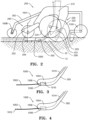
- FIG. 1 illustrates an embodiment of an agricultural planter row unit 200.
- the row unit 200 is comprised of a frame 204 pivotally connected to a toolbar 202 by a parallel linkage 206 enabling each row unit 200 to move vertically independently of the toolbar 202.
- the frame 204 operably supports one or more hoppers 208, a seed meter 210, a seed delivery mechanism 212, a downforce control system 214, a seed trench opening assembly 220, a trench closing assembly 250, a packer wheel assembly 260, and a row cleaner assembly 270.
- the row unit 200 shown in FIG. 7 may be for a conventional planter or the row unit 200 may be a central fill planter, in which case the hoppers 208 may be replaced with one or more mini-hoppers and the frame 204 modified accordingly as would be recognized by those of skill in the art.
- the downforce control system 214 is disposed to apply lift and/or downforce on the row unit 200 such as disclosed in U.S. Publication No. US2014/0090585 .
- the seed trench opening assembly 220 includes a pair of opening discs 222 rotatably supported by a downwardly extending shank member 205 of the frame 204.
- the opening discs 222 are arranged to diverge outwardly and rearwardly so as to open a v-shaped trench 10 in the soil 11 as the planter traverses the field.
- the seed delivery mechanism 212 such as a seed tube or seed conveyor, is positioned between the opening discs 222 to deliver seed from the seed meter 210 into the opened seed trench 10.
- the depth of the seed trench 10 is controlled by a pair of gauge wheels 224 positioned adjacent to the opening discs 222.
- the gauge wheels 224 are rotatably supported by gauge wheel arms 226 which are pivotally secured at one end to the frame 204 about pivot pin 228.
- a rocker arm 230 is pivotally supported on the frame 204 by a pivot pin 232. It should be appreciated that rotation of the rocker arm 230 about the pivot pin 232 sets the depth of the trench 10 by limiting the upward travel of the gauge wheel arms 226 (and thus the gauge wheels) relative to the opening discs 222.
- the rocker arm 230 may be adjustably positioned via a linear actuator 234 mounted to the row unit frame 204 and pivotally coupled to an upper end of the rocker arm 230.
- the linear actuator 234 may be controlled remotely or automatically actuated as disclosed, for example, in International Publication No. WO2014/186810 .
- a downforce sensor 238 is configured to generate a signal related to the amount of force imposed by the gauge wheels 224 on the soil.
- the pivot pin 232 for the rocker arm 230 may comprise the downforce sensor 238, such as the instrumented pins disclosed in U.S. Patent No. 8561472 .
- the seed meter 210 may be any commercially available seed meter, such as the fingertype meter or vacuum seed meter, such as the VSet ® meter, available from Precision Planting LLC, 23207 Townline Rd, Tremont, IL 61568 .
- the trench closing assembly 250 includes a closing wheel arm 252 which pivotally attaches to the row unit frame 204.
- a pair of offset closing wheels 254 are rotatably attached to the closing wheel arm 252 and are angularly disposed to "close" the seed trench 10 by pushing the walls of the open seed trench back together over the deposited seed 12.
- An actuator 256 may be pivotally attached at one end to the closing wheel arm 252 and at its other end to the row unit frame 204 to vary the down pressure exerted by the closing wheels 254 depending on soil conditions.
- the closing wheel assembly 250 may be of the type disclosed in International Publication No. WO2014/066650 .
- the packer wheel assembly 260 comprises an arm 262 pivotally attached to the row unit fame 204 and extends rearward of the closing wheel assembly 250 and in alignment therewith.
- the arm 262 rotatably supports a packer wheel 264.
- An actuator 266 is pivotally attached at one end to the arm 262 and at its other end to the row unit frame 204 to vary the amount of downforce exerted by the packer wheel 264 to pack the soil over the seed trench 10.
- the row cleaner assembly 270 may be the CleanSweep ® system available from Precision Planting LLC, 23207 Townline Rd, Tremont, IL 61568 .
- the row cleaner assembly 270 includes an arm 272 pivotally attached to the forward end of the row unit frame 204 and aligned with the trench opening assembly 220.
- a pair of row cleaner wheels 274 are rotatably attached to the forward end of the arm 272.
- An actuator 276 is pivotally attached at one end to the arm 272 and at its other end to the row unit frame 204 to adjust the downforce on the arm to vary the aggressiveness of the action of the row cleaning wheels 274 depending on the amount of crop residue and soil conditions.
- a monitor 300 is visible to an operator within the cab of a tractor pulling the planter.
- the monitor 300 may be in signal communication with a GPS unit 310, the trench closing assembly actuator 256 and the packer wheel assembly actuator 266 to enable operational control of the trench closing assembly 250 and the packer wheel assembly 260 (discussed later) based on the signals generated by the trench closing sensors 1000.
- the monitor 300 may be programmed to display operational recommendations based on the signals generated by the trench closing sensors 1000.
- the monitor 300 may also be in signal communication with the row cleaner actuator 276, the downforce control system 214, the depth adjustment actuator 234 to enable operational control of row cleaner assembly 270, the downforce control system 214 and the trench opening assembly 230, respectively.
- FIG. 2 illustrates a trench closing sensor 1000 to determine if the closing wheel assembly 250 is sufficiently closing the open seed trench 10 with soil and/or to determine the amount of compaction of the soil over the seed within the seed trench 10.
- the trench closing sensor 1000 comprises wire, string or other suitable elongate member (hereinafter referred to as the "drag wire" 1002) disposed to drag in the seed trench 10.
- drag wire elongate member
- the trench closing sensor 1000 measures or detects whether the seed trench is being adequately closed with soil by measuring the amount of force required to pull the wire through the soil or by measuring the amount of strain, pulling force or tension in the wire or by measuring the amount of soil pressure acting on the wire.
- the end of the drag wire may terminate proximate to the vertical axis 1001 extending through the center of the closing wheel 254 of the closing wheel assembly 250 of the row unit 200 or several inches rearward of the vertical axis 1001.
- the drag wire 1002 may be supported by any suitable structure that permits the rearward end of the drag wire 1002 to drag within the seed trench 10.
- the drag wire 1002 may be supported from the seed tube 212, the seed tube guard 290, the shank 205, or from another appurtenance 292 aligned with the seed trench.
- one such appurtenance 292 may be a seed firmer, such as a Keeton ® seed firmer, or a FurrowJet TM , both of which are well known in the art and available from Precision Planting, LLC, 23207 Townline Rd, Tremont, IL 61568 .
- FIG. 3 is an embodiment of seed firmer appurtenance 292 adapted to function as trench closing sensor 1000.
- the plastic body 1004 of the seed firmer 292 includes a cavity 1006 formed within the body.
- the rearward end of the drag wire 1002 extends outwardly from the rear of the body 1004 through an aperture 1008.
- the forwarded end of the drag wire 1002 may be coupled to an instrument 1010 (such strain gauge, a hall effect sensor or a potentiometer) disposed within the cavity 1006.
- the signals generated by the instrument 1010 are communicated to the monitor 300 by signal wires 1014.
- any drag wire described herein, such as drag wire 1002 can be replaced with fluid tube 3002, and instrument 1010 is a pressure sensor.
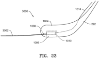
- FIG. 23 is a modification of FIG. 3 which shows a trench closing sensor 3000 with a fluid tube 3002. All other aspects of closing sensor 3000 may remain the same as the closing sensor 1000.
- the fluid tube 3002 is filled with a fluid (gas or liquid) and connected to instrument 1010. As soil is added around fluid tube 3002, fluid tube 3002 compresses, and the pressure in fluid tube 3002 is increased and is measured by instrument 1010.
- fluid tube 3002 is not elongatable fore to aft (in line with the direction of travel) so that any pressure change that would be caused by elongation is minimized or eliminated.
- fluid tube may have a rigid side that does not elongate. In one embodiment, at least 20% or at least 25% of the circumference/perimeter of fluid tube 3002 is rigid and the remainder is compressible. In cross-section, the fluid tube 3002 may be circular or the fluid tube 3002 may be square or polygonal in shape and may have one, two, or three rigid sides.
- the closing wheels 254 of the trench closing assembly 250 close the open seed trench 10 by pushing the walls of the seed trench 10 back together over the deposited seed 12 and the drag wire 1002.
- the instrument 1010 measures the strain on the drag wire 1002, or the amount of pulling force or tension exerted on the drag wire 1002. It should be appreciated that if the seed trench 10 is optimally closed producing good seed-to-soil contact, the instrument 1010 will measure a greater strain, tension or pulling force than if the seed trench is poorly closed. Likewise, the instrument 1010 can detect if the trench closing assembly 250 is excessively compacting the soil or inadequately packing the soil depending on the strain, tension or pulling force required to pull the drag wire 1002 through the closed trench.
- FIG. 4 illustrates an embodiment in which a pressure transducer 1012, such as a piezoresistive or piezoelectric transducer, is coupled to the rearward end of the drag wire 1002 to measure the pressure being exerted on the transducer 1012 by the surrounding soil pushed into the seed trench 10 by the closing wheel assembly 250.
- the pressure detected by the transducer 1012 is communicated by signal wires 1014 to the monitor 300. It should be appreciated that the more soil pushed into the seed trench 10 by the closing wheel assembly 250, the more soil covers the transducer 1012 generating a higher pressure measurement. Conversely, if the closing wheel assembly is not pushing a sufficient amount of soil into the seed trench to adequately cover the seed, the transducer 1012 will measure a lower pressure.
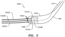
- FIG. 5 illustrates another embodiment in which multiple drag wires 1002A, 1002B, 1002C are stacked vertically, each coupled to a respective instrument 1010A, 1010B, 1010C (such strain gauge, a hall effect sensor or a potentiometer) disposed within the cavity 1006 so as to provide a profile perspective of the trench closure.
- a respective instrument 1010A, 1010B, 1010C such strain gauge, a hall effect sensor or a potentiometer
- each of the stacked the drag wires 1002 may be instrumented with a pressure transducer as described above or one of more of the stacked wires may be instrumented with a pressure transducer while other wires are coupled to an instrument 1010 disposed within the cavity 1006.
- Each drag wire 1002 may have a different geometry, length or diameter as compared to other drag wires 1002. The different geometries or diameters may provide a different signal response for different areas within the trench.
- multiple drag wires 1002A, 1002B, 1002C can be stacked horizontally (not shown), or a combination of horizontal and vertical stacks (not shown).
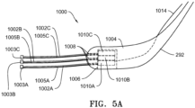
- instrument 1010A, 1010B, and 1010C may send an electrical current to multiple drag wires 1002A, 1002B, and 1002C, respectively. If any of drag wires 1002A, 1002B, or 1002C make contact, an electrical circuit will be formed, and instruments 1010A, 1010B, and 1010C may then determine which drag wires 1002A, 1002B, and 1002C are in contact with one another. This information may be sent to monitor 300 by signal wire 1014. Knowing whether the multiple drag wires 1002A, 1002B, and 1002C are touching provides information about whether multiple drag wires 1002A, 1002B, and 1002C are sensing the same location or different locations.
- multiple drag wires 1002A, 1002B, and 1002C are measuring the same location and provides another measurement to determine whether the furrow is open or closed. For example, if the furrow is open, multiple drag wires 1002A, 1002B, and 1002C would fall under gravity and contact one another.
- conductive tips 1003A, 1003B, and 1003C may be added to the ends of multiple drag wires 1002A, 1002B, and 1002C, respectively, at the end opposite instrument 1010A, 1010B, and 1010C, respectively, or to fluid tube 3002.
- the conductive tips 1003A, 1003B, and 1003C are connected to instrument 1010A, 1010B, and 1010C, respectively, by wires 1005A, 1005B, and 1005C, respectively.
- drag wire 1002 may further include at least one wear protector 1009 disposed over drag wire 1002.
- Wear protector 1009 may be a single piece, or wear protector 1009 can be a plurality of pieces. Whether as a single piece or as a plurality of pieces, wear protector 1009 may cover from greater than 0 up to 100% of drag wire 1002. In certain embodiments, the percentage of coverage of drag wire 1002 extending from body of the firmer is 40 to 60%, about 50%, greater than 90%, or 95-99%.
- Wear protector 1009 may be made from any material that increases wear resistance compared to the material of drag wire 1002. In one embodiment, wear protector 1009 is made from tungsten carbide. Tungsten carbide can provide increase wear resistance, but tungsten carbide can be brittle. As such, in one embodiment, a wear protector 1009 made from tungsten carbide is a plurality of pieces, such as shown in FIG. 25 .
- FIG. 26 illustrates another embodiment of a trench closing sensor 4000.
- trench closing sensor 4000 has a first body 4004 and a second body 4001.
- the second body 4001 may be detachable from the first body 4004 by any suitable attachment, such as a fastener, nut and bolt, screw, and/or clip.
- the second body 4001 has a member 4003 (such as a plate) attached to a pivot 4002 at one end, and drag wire 1002 is disposed at the other end of 4003. The drag wire 1002 is then disposed through second body 4001 and extends rearward.
- Plate 4003 pivots about pivot 4002 and extends downward.
- a biasing element 4005 biases plate 4003 forward towards the first body 4004.
- a stop may be provided to prevent movement of plate 4003 too far forward.
- plate 4003 is perpendicular to the ground.
- a transmitter 4007 such as a magnet.
- Transmitter 4007 generates a signal (such as a magnetic field) that is detected by a receiver 4008 (such as a Hall Effect sensor) disposed in the first body 4004.
- the transmitter 4007 may be disposed on plate 4003 on the side facing the first body 4004.
- Receiver 4008 is then in communication with monitor 300 through signal wire 1014.
- Receiver 4008 may first be disposed on a circuit board (not shown) and then connected to signal wire 1014, such as illustrated in FIG. 12 in which other sensors (such as reflectivity or temperature sensors) are disposed in the first body 4004 and connected to a circuit board.
- trench closing sensor 4000 provides for easier replacement of the drag wire 1002 by removing second body 4001 and replacing it with a new second body 4001. This saves time by not having to open the body 4004 in trench closing sensor 4000.
- resilient plate 4009 replaces plate 4003 and pivot 4002.
- Transmitter 4007 is disposed on plate 4009 as with plate 4003.
- resilient plate 4009 deflects when drag wire 1002 pulls on plate 4009, and 4009 returns to its original position when no force is applied.
- plate 4009 may have a T shape.
- transmitter 4007 and receiver 4008 are replaced by sensor system 4030.
- sensor system 4030 is shown with the embodiment of FIG. 27A .
- Sensor system 4030 includes a first magnet 4031, a second magnet 4032, and a Hall Effect sensor 4033.
- First magnet 4031 and second magnet 4032 are disposed in a body/bodies (such as 1004, 4001, 4004) so that the same poles (both N-N or S-S) are oriented towards each other.
- Hall Effect sensor 4033 is disposed equidistant from first magnet 4031 and second magnet 4032 so that the field measured at this middle point is zero.
- First magnet 4031 is disposed on plate 4009 or plate 4003.
- any of the embodiments in FIG. 26, 27A , or 28 may be used in a single body (not shown).
- any of the drag wires 1002 described herein can be made in two parts, a drag wire base section 1002B and drag wire end 1002A, and connected at detachable connection 1011. Having the detachable drag wire end 1002A allows for replacement of the drag wire without having to open body 1004 (or body 4001).
- the signals generated by the trench closing sensor 1000, 3000, 4000 may be communicated by signal wires 1014 to the monitor 300 as the actual measurement or the monitor 300 may be programmed to convert and display on the monitor screen the actual force, tension or pressure measured by the sensor 1000, 3000, 4000 in the seed trench 10 in relation to a desired force, tension or pressure range. If the desired displayed force, tension or pressure is outside the desired range, the downforce on the closing wheel 254 may be adjusted. The adjustment of the closing wheel downforce may be adjusted manually by adjusting the position of a conventional coil spring corresponding to discrete preload settings.
- the operator may manually actuate the trench closing wheel assembly actuator 256 as needed to increase or decrease the amount of downforce exerted by the closing wheels 254 to keep the force, tension or pressure measured by the trench closing sensor 1000 within the desired range.
- the monitor 300 may be programmed to automatically actuate the trench closing wheel assembly actuator 256 to increase or decrease the downforce on the closing wheels 254 depending on whether the trench closing sensor 1000 detects that the force, tension or pressure on the drag wire(s) 1002 falls below or exceeds a predefined minimum and maximum threshold force, tension or pressure.
- the angle of the closing wheels may be adjusted to increase or decrease the aggressiveness of the closing wheels.
- an actuator or mechanical adjustment may be provided to decrease or increase the angle of the closing wheels with respect to the direction of travel or with respect to vertical thereby adjusting the amount of soil the closing wheels push into the seed trench.
- a closing wheel angle actuator is provided to adjust the closing wheel angle, the operator may actuate the actuator manually or the monitor 300 may be programmed to automatically actuate the actuator to adjust the aggressiveness of the closing wheels depending on the force, tension or pressure detected by the trench closing sensor 1000, 3000, 4000.
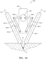
- the camber angle of the closing wheels can be adjusted so that axis A-1 and A-2 through the closing wheels 254-1 and 254-2 intersect the seed 12 in the trench 10.
- the work layer sensors described below can be used to locate the seed 12 in the trench 10.
- the position of the closing system 250 with respect to any of the work layer sensors is known, and closing wheels 254-1 and 254-2 may be adjusted by actuator 259 to adjust the camber angle of closing wheels 254-1 and 254-2.
- the camber angle may be adjusted to intersect the bottom of trench 10.
- seed 12 is at the bottom of trench 10.
- the bottom of trench 10 may be determined by any instrument that determines the depth of trench 10.
- Non-limiting examples of instruments that may determine the depth of trench 10 are disclosed in CN101080968 , CN201072894 , DE102004011302 , JP0614628 , JP2069104 , JP04360604 , JP08168301 , JP2001299010 , JP2006345805 , US4413685 , US4775940 , US5060205 , US6216795 , US8909436 , US20150289438 , US20160037709 , WO2012102667 , WO2015169323 , and U.S. Provisional Application No. 62/365585 .
- closing system 250 includes a closing frame member 253.
- Closing wheels 254-1 and 254-2 are attached to axles 255-1 and 255-2, respectively.
- Axles 255-1 and 255-2 are connected to axle arms 257-1 and 257-2, respectively, which are pivotably connected to frame member 253 and actuator arms 258-1 and 258-2, respectively, which are pivotably connected to the actuator 259.
- the actuator 259 is in communication with monitor 300, wherein the actuator 259 receives signals to rotate, which causes actuator arms 258-1 and 258-2 to move closer or farther from the center of closing frame 253 to cause the angle of axle arms 257-1 and 257-2 with respect to closing frame member 253 to change, which, in turn, changes the camber angles of closing wheels 254-1 and 254-2. While shown with one actuator 259, there can be two actuators 259-1 and 259-2 with axle arm 258-1 connected to actuator 259-1 and axle arm 258-2 connected to actuator 259-2 to allow for independent adjustment of the camber angles of closing wheels 254-1 and 254-2 (not shown).
- the packer wheel assembly 260 may be adjusted based on the tension, pulling force or pressure detected by the drag wire(s) 1002.
- the adjustment of the packer wheel downforce may be adjusted manually by adjusting the position of a conventional coil spring corresponding to discrete preload settings, or, if the packer wheel assembly 260 is equipped with an actuator 266 as previously described, the operator may manually actuate the actuator 266 or the monitor 300 may be programmed to automatically actuate the actuator 266 to increase or decrease the amount of downforce exerted on the packer wheel 264 to keep the force, tension or pressure measured by the trench closing sensor 1000, 3000, 4000 within the desired range.
- a reference sensor 1100 may be provided to "calibrate" the trench closing sensor 1000, 3000, 4000 to account for conditions that may have an effect on the drag coefficient properties of the soil, including such factors as planter speed, trench depth, soil texture, soil moisture and soil density.
- the reference sensor 1100 includes a drag member 1102 which is disposed to drag through the soil outside of the seed trench 10.
- the reference sensor 1100 may be disposed forward of the trench opening assembly 220 as shown in FIG. 2 or the drag member 1102 may be mounted between the row units 200 (not shown).
- the drag member 1102 is supported by an arm 1104 which is adjustably positionable with respect to a gauge wheel 1106 to vary the penetration depth of the drag member 1102 with respect to the soil surface.
- the arm 1104 is instrumented with a strain gauge 1110 to detect the strain exerted on the arm 1104 as the drag member 1102 drags through the soil.
- Signal wires 1114 transmit the electrical resistance change in the strain gauge 1110 to the monitor 300.
- the monitor 300 is programmed to correlate the electrical resistance change to detected strain in the arm 1104 which can then be correlated with the signals generated by the trench closing sensor 1000 to define the range of the force, tension or pressure that the trench closing sensor 1000 should be detecting if the seed trench is being adequately closed by the trench closing assembly 250.
- the reference sensor 1100 may be the penetration force of row unit 200.
- the penetration force be measured directly with force sensor 223, such as a strain gauge, disposed at the opener disc spindle 225 as illustrated in FIG. 2 .
- the penetration force of row unit 200 may also be determined by subtracting the gauge wheel force measured by downforce sensor 238 from the applied force as applied by the downforce control system 214 and the mass of row unit 200.
- the reference sensor 1100 may be the electrical conductivity or reflectance of the soil. Suitable sensors for electrical conductivity and reflectance are described in WO2015/171908 , which is incorporated herein by reference in its entirety.
- the seed firmer appurtenance 292 of FIG. 3 further contains the reflectivity sensors 350a and 350b, electrical conductivity sensors 370f and 370r of seed firmer 400 shown in FIG. 4a of WO2015/171908 . While this embodiment shown a wireless transmitter 62-1, which is in data communication with monitor 300, the data communication to monitor 300 can be wired.
- temperature sensor 360 is shown in FIG. 12 (from FIG. 4A from WO2015/171908 ) is temperature sensor 360, removable portion 492, male coupler 472, and female coupler 474.
- the reference sensor 1100 may be the geospatial soil type information based on GPS location, such as the USDA SSURGO data, which may be useful when changing zones in the field.
- GPS location such as the USDA SSURGO data
- the data for each zone in the field can be the reference.
- An alternative reference sensor 1100A illustrated in FIG. 13 , includes a coulter arm 2001 attached to row unit 200 with a coulter 2002 attached to coulter arm 2001 with axle 2003.
- a force sensor 2004, such as downforce sensor 238, measures the force that coulter 2002 transmits to axle 2003.
- Force sensor 2004 is in data communication with monitor 300.
- An alternative reference sensor 1100B illustrated in FIG. 14 , includes arm 3001 mounted to row unit 200 (or alternatively to toolbar 202), and at the opposite end of arm 3001 is bracket 3002.
- bracket 3002 a coulter arm 3003 is pivotably mounted, and a force device 3004, such as a spring, is disposed to connect coulter arm 3003 to bracket 3002 to apply a fixed force to coulter arm 3003.
- the force device may be a pneumatic device, hydraulic device, an electromechanical device, or an electro-hydraulic device.
- a coulter 3008 is rollingly mounted to coulter arm 3003.
- a gauge wheel arm 3005 is pivotably connected to coulter arm 3003, and a gauge wheel 3007 is rollingly mounted to gauge wheel arm 3005.
- An angle sensor 3006 is disposed at the pivoting connection between gauge wheel arm 3005 and coulter arm 3003.
- Examples of angle sensor 3006 include, but are not limited to, a rotary potentiometer or Hall-effect sensor.
- Angle sensor 3006 is in data communication with monitor 300.
- force device 3004 applies a known force to coulter 3008. As the hardness of the soil changes, gauge wheel arm 3005 will rotate, and angle sensor 3006 measures the amount of rotation.
- the speed of row unit 200 is the speed of row unit 200. As the speed of travel changes, the force, tension or pressure measured will directly change with the change in speed.
- the speed of row unit 200 may be determined by any suitable device, such as a speedometer on the tractor (tractor wheel speed), GPS distance change over time, or ground speed radar. Any of these devices may be in data communication with monitor 300.
- FIG. 9 is a schematic illustration of a system 500 which employs the trench closing sensors 1000, 3000, 4000 and reference sensors 1100 to provide operator feedback and to control the closing wheel assembly 250 and packer wheel assembly 260 of the planter row unit 200.
- the reference sensor 1100 detects the strain (via the strain gauge 1110) exerted on the arm 1104.
- the strain exerted on the arm 1104 is correlated to define the range of force, tension or pressure that should be detecting if the seed trench is being adequately closed by the trench closing assembly 250.
- the trench closing sensor 1000, 3000, 4000 detects the force, tension or pressure exerted by the soil on the drag wire(s) 1002.
- the force, tension or pressure exerted by the soil on the drag wire(s) 1002 of the trench closing sensor 1000, 3000, 4000 may be displayed to the operator on the monitor 300 in the cab of the tractor in relation to the correlated range of the force, tension or pressure that the trench closing sensor 1000, 3000, 4000 should be detecting if the seed trench is being adequately closed by the trench closing assembly 250.
- control decisions are made based on the comparison of the characterized range with the force, tension or pressure detected by that the trench closing sensor 1000, 3000, 4000.
- the closing wheel assembly 250 or the packer wheel assembly 260 may be controlled by the monitor 300 generating signals to actuate one or more of the corresponding actuators 256, 266 and/or at step 522, corresponding recommendations may be displayed to the operator on the monitor display.
- FIG. 10 shows an embodiment of a trench sensor system 2000.
- the trench sensor system 2000 has one or both of a trench sensor 2010 and ground sensor 2020.
- Trench sensor 2010 is disposed on closing system 250 after the opening assembly 220 in a direction of travel to sense the distance to the bottom of seed trench 10.
- Ground sensor 2020 is disposed on row unit 200 after trench sensor 2010 in a direction of travel to sense the distance to soil surface 1. Both trench sensor 2010 and ground sensor 2020 are at a fixed distance to the bottom of closing wheels 254, and both are in communication with monitor 300.
- the depth (H G ) of closing wheels 254 in the soil can be determined by subtracting a distance measured by ground sensor 2020 from the distance of ground sensor 2020 to the bottom of closing wheels 254.
- the distance (H F ) of closing wheels 254 above the bottom of seed trench 10 can be determined by subtracting the distance of trench sensor 2010 to the bottom of closing wheels 254 from a distance measured by trench sensor 2010. One or both of these measurements may also be used in combination with the measurements of the trench closing sensor 1000, 3000, 4000 to determine closing effectiveness.
- Trench sensor 2010 and ground sensor 2020 may each independently be an ultrasonic sensor, radar, or a laser.
- an angle sensor 2280 can be disposed at the connection of closing wheel arm 252 and frame 204, and angle sensor 2280 is in communication with monitor 300.
- the angle sensor 2280 can be the same as the pivot arm angle sensor 280 in WO2014/066650 .
- the angular output of angle sensor 2280 can be combined with the measurements of the trench closing sensor 1000, 3000, 4000 to determine closing effectiveness of the seed trench.
- Examples of angle sensor 2280 include, but are not limited to, rotary potentiometer and Hall-effect sensor.
- Work layer sensors 100 such as disclosed in PCT Application No. PCT/US2016/031201 , may be disposed on row unit 200 to generate a signal or image representative of the soil densities or other soil characteristics throughout a soil region of interest, hereinafter referred to as the "work layer" 104.
- Work layer sensors 100 may determine the effectiveness of the closing of the trench to identify if there are any void spaces in the closed trench.
- the work layer sensors may be used in conjunction with the trench closing sensor 1000, 3000, 4000.
- FIGs. 15 , 17 and 19 schematically illustrate alternative embodiments of a work layer sensor 100.
- the representative image or signal generated by the work layer sensor 100 is hereinafter referred to as the "work layer image" 110.
- the work layer sensors 100 may be mounted to a planter row unit 200 ( FIG. 1 ) for generating a work layer image 110 of the seed trench as the planter traverses the field.
- the work layer image 110 may be displayed on a monitor 300 visible to an operator within the cab of a tractor and the planter may be equipped with various actuators for controlling the planter based on the characteristics of the work layer 104 as determined from the work layer image 110.
- the work layer sensor 100 for generating the work layer image 110 may comprise a ground penetrating radar system, an ultrasound system, an audible range sound system, an electrical current system or any other suitable system for generating an electromagnetic field 102 through the work layer 104 to produce the work layer image 110. It should be understood that the depth and width of the work layer 104 may vary depending on the agricultural implement and operation being performed.
- FIG. 15 is a schematic illustration of one embodiment of a work layer sensor 100-1 disposed in relation to a seed trench 10 formed in the soil 11 by a planter, wherein the seed trench 10 comprises the soil region of interest or work layer 104.
- the work layer sensor 100-1 comprises a transmitter (T1) disposed on one side of the seed trench 10 and a receiver (R1) disposed on the other side of the seed trench 10 to produce the electromagnetic field 102 through the seed trench to generate the work layer image 110.
- the work layer sensor 100 may comprise a ground-penetration radar subsurface inspection system such as any of the following commercially available systems: (1) the StructureScan TM Mini HR available from GSSI in Nashua, New Hampshire; (2) the 3d-Radar GeoScope TM Mk IV coupled to a 3d-Radar VX-Series and/or DX-Series multi-channel antenna, all available from 3d-Radar AS in Trondheim, Norway; or (3) the MALA Imaging Radar Array System available from MALA Geoscience in Mala, Sweden.
- a ground-penetration radar subsurface inspection system such as any of the following commercially available systems: (1) the StructureScan TM Mini HR available from GSSI in Nashua, New Hampshire; (2) the 3d-Radar GeoScope TM Mk IV coupled to a 3d-Radar VX-Series and/or DX-Series multi-channel antenna, all available from 3d-Radar AS in Trondheim, Norway; or (3) the MALA Imaging Radar
- the commercially available system may be mounted to the planter or other implement, or may be mounted to a cart which moves with the implement; in either case the system is preferably disposed to capture an image of a work layer in the area of interest (e.g., the seed trench).
- the work layer image 110 may be generated from the signal outputs of the work layer sensor 100 using commercially available software such as GPR-SLICE (e.g., version 7.0) available from GeoHiRes International Ltd. located in Borken, Germany.
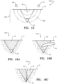
- FIGs. 16A-16C are intended to be representative examples of work layer images 110 generated by the work layer sensor 100-1 of FIG. 15 showing various characteristics of the seed trench 10, including, for example, the trench depth, the trench shape, depth of seed 12, the seed depth relative to the trench depth, crop residue 14 in the trench, and the void spaces 16 within the trench.
- the work layer images 110 may be used to determine other characteristics of the work layer 104, including, for example, the seed-to-soil contact, percentage of trench closed, percentage of upper half of trench closed, percentage of lower half of trench closed, moisture of the soil, etc.
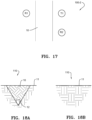
- FIG. 17 schematically illustrates, in plan view, another embodiment of a work layer sensor 100-2 disposed with respect to a seed trench 10.
- a transmitter (T1) is disposed on one side of the seed trench 10
- a first receiver (R1) is disposed on the other side of the seed trench 10
- a second receiver (R2) is disposed adjacent and rearward of the transmitter (T1).
- FIG. 18A is a representative illustration of the work layer image 110 generated through the trench between the transmitter (T1) and the first receiver (R1))
- FIG. 18B is a representative illustration of the work layer image 110 generated between the transmitter (T1) and the second receiver (R2) providing an image of the undisturbed soil adjacent to the seed trench.
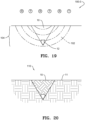
- FIG. 19 is an elevation view schematically illustrating another work layer sensor embodiment 100-3 disposed with respect to a seed trench 10.
- the work layer sensor 100-3 comprises a plurality of transmitter and receiver pairs disposed above and transverse to the seed trench 10.
- FIG. 20 is a representative illustration of the work layer image 110 generated by the work layer sensor 100-3 of FIG. 5 which provides a view not only of the seed trench but also a portion of the soil adjacent to each side of the seed trench.
- the frequency of operation of the work layer sensors 100 and the vertical position of the transmitters (T) and receivers (R) above the soil and the spacing between the transmitters (T) and receivers (R) are selected to minimize signal to noise ratio while also capturing the desired depth and width of the soil region of interest (the work layer 104) for which the work layer image 110 is generated.
- FIG. 1 illustrates one example of a particular application of the work layer sensors 100 disposed on a row unit 200 of an agricultural planter.
- the row unit 200 includes a work layer sensor 100A disposed on a forward end of the row unit 200 and a work layer sensor 100B disposed rearward end of the row unit 200.
- the forward and rearward work layer sensors 100A, 100B may comprise any of the embodiments of the work layer sensors 100-1, 100-2, 100-3 previously described.
- the forward work layer sensor 100A is disposed to generate a reference work layer image (hereinafter a "reference layer image") 110A of the soil prior to the soil being disturbed by the planter, whereas the rearward work layer sensor 100B generates the work layer image 110B, which in this example, is the image of the closed seed trench 10 in which the seed has been deposited and covered with soil.
- a reference image 110A and the work layer image 110B for analysis of the soil characteristics through the work layer 104.
- the forward and rearward work layer sensors 100A, 100B referenced in FIG. 1 may employ any of the embodiments 100-1, 100-2 or 100-3 previously described. However, it should be appreciated that if the embodiments 100-2 or 100-3 are employed, the forward work layer sensor 100A may be eliminated because the embodiments 100-2 and 100-3 are configured to generate the work layer images 110 of undisturbed soil adjacent to the seed trench 10 which could serve as the reference layer image 110A.
- the work layer sensors may be positioned after the row cleaner assembly 270 and before the trench opening assembly 220 or in one or more other locations between the trench opening discs 222 and the closing wheels 254 or the packing wheel 264 depending on the soil region or characteristics of interest.
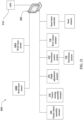
- FIG. 21 is a schematic illustration of a system 600 which employs work layer sensors 100 to provide operator feedback and to control the planter row unit 200.
- Work layer sensors 100A, 100B are disposed to generate a reference layer image 110A of undisturbed soil and a work layer image 110B of the closed seed trench (i.e., after seed is deposited, covered with soil by the closing wheel assembly 250 and the soil packed with the packing wheel assembly 260).
- the work layer sensors 100A, 100B may be separate work layer sensors disposed forward and rearward of the row unit 200 as illustrated in FIG. 7 , or the work layer sensors 100A, 100B may comprise a single work layer sensor with transmitters (T) and receivers (R) disposed to generate both a reference layer image 110A and a work layer image 110B.
- the work layer image 110B may be communicated and displayed to the operator on a monitor 300 comprising a display, a controller and user interface such as a graphical user interface (GUI), within the cab of the tractor.
- GUI graphical user interface
- the monitor 300 may be in signal communication with a GPS unit 310, the row cleaner actuator 276, the downforce control system 214, the depth adjustment actuator 234, the trench closing assembly actuator 256 and the packer wheel assembly actuator 266 to enable operational control of the planter based on the characteristics of the work layer image 110B.
- a signal is generated by the monitor 300 to actuate the row cleaner actuator 276 to increase row cleaner downforce.
- a signal is generated by the monitor 300 to actuate the downforce control system 214 to increase the downforce and/or to actuate the depth adjustment actuator 234 to adjust the gauge wheels 234 relative to the opening discs 232 to increase the trench depth.
- a signal is generated by the monitor 300 to actuate the downforce control system 214 to decrease the downforce and/or to actuate the depth adjustment actuator 234 to decrease the trench depth.
- a signal is generated by the monitor 300 to actuate the trench closing wheel assembly actuator 256 to increase the downforce on the closing wheels 254.
- a signal is generated by the monitor 300 to actuate the packer wheel assembly actuator 266 to increase the downforce on the packer wheel 264.
- the work layer image 110B may identify and/or analyze (e.g., determine depth, area, volume, density or other qualities or quantities of) subterranean features of interest such as tile lines, large rocks, or compaction layers resulting from tillage and other field traffic.
- subterranean features may be displayed to the user on the monitor 300 and/or identified by the monitor 300 using an empirical correlation between image properties and a set of subterranean features expected to be encountered in the field.
- the area traversed by the gauge wheels (or other wheels) of the planter (or tractor or other implement or vehicle) may be analyzed to determine a depth and/or soil density of a compaction layer beneath the wheels.
- the area of the work layer image may be divided into subregions for analysis based on anticipated subterranean features in such sub-regions (e.g., the area traversed by the gauge wheels may be analyzed for compaction).
- the monitor 300 may estimate a soil property (e.g., soil moisture, organic matter, or electrical conductivity, water table level) based on image properties of the work layer image 110B and display the soil property to the user as a numerical (e.g., average or current) value or a spatial map of the soil property at geo-referenced locations in the field associated with each soil property measurement (e.g., by correlating measurements with concurrent geo-referenced locations reported the GPS unit 310).
- a soil property e.g., soil moisture, organic matter, or electrical conductivity, water table level
- the monitor 300 could be programmed to display operational recommendations based on the characteristics of the work layer image 110B. For example, if the work layer image 110B identifies that the seed 12 is irregularly spaced in the trench 10 or if the seed 12 is not being uniformly deposited in the base of the trench, or if the spacing of the seed 12 in the trench does not match the anticipated spacing of the seed based on the signals generated by the seed sensor or speed of the seed meter, such irregular spacing, nonuniform positioning or other inconsistencies with anticipated spacing may be due to excess speed causing seed bounce within the trench or excess vertical acceleration of the row unit.
- the monitor 300 may be programmed to recommend decreasing the planting speed or to suggest increasing downforce (if not automatically controlled as previously described) to reduce vertical acceleration of the planter row units.
- the monitor may be programmed to display recommendations to the operator to make manual or remote adjustments as previously described based on the characteristics of the work layer image 110B.
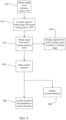
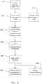
- FIG. 22 illustrates the process steps for controlling the planter and providing operator feedback.
- the reference image 110A and work layer image 110B is generated by the work image sensor(s) 100.
- the work layer image 110B may be displayed to the operator on the monitor 300 in the cab of the tractor.
- the reference layer image 110A is compared with the work layer image 110B to characterize the work layer image.
- the characterized work layer image 110B is compared to predetermined thresholds.
- control decisions are made based on the comparison of the characterized work layer image 110B with the predetermined thresholds.
- the planter components may be controlled by the monitor 300 generating signals to actuate one or more of the corresponding actuators 276, 214, 234, 256, 266 and/or at step 624, corresponding recommendations may be displayed to the operator on the monitor display.
- the monitor 300 compares one or more characteristics (e.g., density) of the reference image 110A with the same characteristics of the work layer image 110B.
- a characterized image may be generated comprising only portions of the work layer image differing from the reference image by at least a threshold value. The characterized image may then be used to identify and define features of the work layer image 110B, such as the trench shape, the trench depth, residue in the trench, seeds and seed placement within the trench, void spaces within the trench, and density differences of the soil within the trench.
- the seed is identified or identifiable from the work layer image 110B by determining regions within the work layer image having a size or shape corresponding to a seed and having a density range empirically corresponding to seed.
- the vertical position of the seed with respect to the soil surface is readily measurable or determined.
- the amount of residue in the trench can be determined by (a) defining the area of the trench cross-section (based on soil density differences between the reference image 110A and the work layer image 110B); (b) by identifying the regions within the trench having a density range empirically corresponding to residue; (c) totaling the area of the regions corresponding to residue; and (d) dividing the residue area by the trench cross-sectional area.
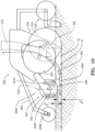
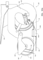
- FIG. 30 illustrates an embodiment for detecting seed trench depth utilizing a radar 710 disposed on the trench closing assembly 250 to send a signal to the ground and to an elongate member 800 (such as the drag wire 1002 described above).
- Radar 710 is in signal communication with monitor 300.
- the radar 710 uses a frequency modulated continuous wave signal. Two reflections are returned to radar 710.
- an amplitude versus frequency graph will show a first peak 711 representing the ground reflection and a second peak 712 representing drag wire 1002 reflection. Depth measurement is proportional to the frequency difference between first peak 711 and second peak 712.
- radar 710 may provide the surface profile of the closed trench, which can be achieved using a Texas Instruments mmWave chip in radar 710.
- elongate member 800 only needs to reflect a radar signal, but elongate member 800 can be any elongate member described above, such as drag wire 1002 or fluid tube 3002. Radar 710 can be used in conjunction with any of the following embodiments.
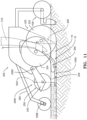
- FIG. 32A illustrates an embodiment for detecting seed trench depth utilizing a Hall effect sensor 720 to measure distance to an elongate member 800.
- the elongate member 800 may be a looped wire 801 with a current flowing through the looped wire 801 to generate a magnetic field.
- the Hall effect sensor 720 is connected to the agricultural implement (agricultural row planter row unit 200 as illustrated) and is biased to engage the ground above looped wire 801. As illustrated, Hall effect sensor 720 is attached to closing system 250 through biasing elements 729 (e.g., springs). Both Hall effect sensor 720 and looped wire 801 are in signal communication with monitor 300.
- biasing elements 729 e.g., springs
- elongate member 800 can have a magnet 802 disposed on elongate member 800, which is illustrated in FIG. 32B .
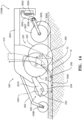
- FIG. 33 illustrates an embodiment for detecting seed trench depth and utilizing similar structure to FIG. 32B , except that an electromagnetic induction (EMI) coil 730 is used in place of Hall effect sensor 720.
- EMI coil 730 is in signal communication with monitor 300.
- Elongate member 800 causes a change in induction, which can be read as distance to elongate member 800 (depth).
- FIG. 34 illustrates an embodiment for detecting seed trench depth utilizing a radio signal generator and phase detector 740 (which could be two separate components) disposed on the agricultural implement, such as on closing system 250, and generates a radio signal.
- Elongate member 800 can either be the transmitting antenna or the receiving antenna, and antenna 741 is either the receiving antenna or transmitting antenna opposite elongate member 800.
- Radio signal generator and phase detector 740 is in signal communication with monitor 300.
- a radio frequency is generated and transmitted by elongate member 800 (or antenna 741) and received by antenna 741 (or elongate member 800).
- the frequency used is generally two times the expected depth but short enough for adequate resolution. Depth is a function of the phase shift between the transmitted and received signals.
- antenna 741 can be disposed on a mud flap (not shown) connected to and disposed after the closing system 250.
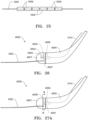
- FIG. 35 illustrates an alternative embodiment for detecting seed trench depth for any of the embodiments of FIGs. 32A-34 utilizing biasing elements 729.
- the biasing elements 729 may be replaced with a bracket 725 as shown in FIG. 35 which is connected to the agricultural implement, such as closing system 250.
- a ski 727 is attached through a biased pivot 726 to bracket 725 to bias any of Hall effect sensor 720, EMI coil 730, or antenna 741to the ground to maintain contact with the ground.
- Hall effect sensor 720 is illustrated, but EMI coil 730 or antenna 741 can replace Hall effect sensor 720.
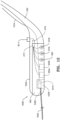
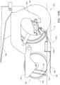
- FIG. 36 illustrates an example for detecting seed trench depth not in accordance with the claimed invention utilizing an antenna 742 pivotally connected to body 1004 and biased to contact the ground adjacent the trench to maintain contact with the trench.
- elongate member 800 may either be the transmitting antenna or the receiving antenna.
- Antenna 742 is either the receiving antenna or transmitting antenna opposite elongate member 800.
- Radio signal generator and phase detector 740 is in signal communication with the monitor 300.
- a radio frequency is generated and transmitted by elongate member 800 (or antenna 742) and received by antenna 742 (or elongate member 800).
- the frequency used is generally two times the expected depth but short enough for adequate resolution. Depth is a function of the phase shift between the transmitted and received signals.
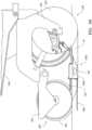
- FIG. 37 illustrates another example for detecting seed trench depth not in accordance with the claimed invention utilizing an antenna 743 connected to body 1004 and disposed rearwardly and above elongated member 800 but not as far as elongated member 800. Both extend into the closed trench. A gap in the lengths of elongated member 800 and antenna 743 is needed for the radar signal.
- a radar 750 may be disposed in body 1004. Radar 750 is in signal communication with monitor 300. In one example, the radar 750 uses a frequency modulated continuous wave signal.
- Elongate member 800 is either a transmitting or receiving antenna connected to radar 750
- antenna 743 is either the receiving antenna or transmitting antenna opposite elongate member 800.
- a radar signal is directed up from elongate member 800 (or antenna 743) and is received by antenna 743 (or elongate member 800).
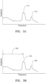
- a graph of amplitude versus frequency will show a first peak 751 and a second peak 752.
- First peak 751 represents the reflection of the ground surface in the closed trench.
- Second peak 752 represents noise.
- Depth measurement is proportional to the frequency of first pulse 753.
- the elongate member 800 may be the drag wire 1002 described above in connection with the trench closing sensors or the elongate member described in each of the embodiments of FIGs. 30 and 32-35 .
- the trench depth can be changed by any actuator that changes trench depth.
- actuators to modify trench depth can be found in International Patent Application Nos. PCT/US2017/18274 and PCT/US2017/18269 .
- radar 710 can be disposed on the trench closing assembly 250 as is illustrated in FIG. 30 .
- radar 710 can alternatively be an ultrasonic transceiver.
- the trench closing sensors 1000, 3000, 4000 or the trench depth measuring devices above are not required in this embodiment, but either or both may be used in combination with this embodiment.
- Radar 710 (or ultrasonic transceiver or a combination of an ultrasonic transmitter and ultrasonic receiver) measure a distance to the ground. The distance to the ground provides a ride quality for the trench closing assembly 250.
- Actuator 256 can be adjusted to change the position of trench closing assembly 250 or the downforce applied to trench closing assembly 250 to achieve a selected position for the trench closing assembly 250. Changes in the position of trench closing assembly 250 may result from changes to the depth of trench opening assembly 220.
- any of the above described embodiments can be used with an air seeder (not shown), which also has a seed trench opening assembly and closing assembly.
Landscapes
- Life Sciences & Earth Sciences (AREA)
- Soil Sciences (AREA)
- Environmental Sciences (AREA)
- Engineering & Computer Science (AREA)
- Mechanical Engineering (AREA)
- Physics & Mathematics (AREA)
- General Physics & Mathematics (AREA)
- Chemical & Material Sciences (AREA)
- Health & Medical Sciences (AREA)
- Electromagnetism (AREA)
- Zoology (AREA)
- Remote Sensing (AREA)
- Biochemistry (AREA)
- General Life Sciences & Earth Sciences (AREA)
- Environmental & Geological Engineering (AREA)
- Food Science & Technology (AREA)
- Medicinal Chemistry (AREA)
- Analytical Chemistry (AREA)
- Geology (AREA)
- General Health & Medical Sciences (AREA)
- Immunology (AREA)
- Pathology (AREA)
- Sowing (AREA)
- Lifting Devices For Agricultural Implements (AREA)
- Soil Working Implements (AREA)
Claims (7)
- Outil agricole, comprenant :un assemblage d'ouverture de sillon (220) ;un assemblage de fermeture de sillon (250) ;un capteur de profondeur de sillon comprenant une première partie et une deuxième partie, ladite première partie comprenant au moins un élément allongé (800), la première partie étant disposée sur l'outil de sorte que, en utilisation, ledit au moins un élément allongé (800) soit disposé dans un sillon (10) dans une surface du sol ouverte par ledit assemblage d'ouverture de sillon (250), ladite deuxième partie étant reliée fonctionnellement à l'outil agricole et disposée pour mesurer une distance audit élément allongé (800), dans lequel la deuxième partie est disposée sur ledit élément allongé (800) ;caractérisé en ce que :
ladite deuxième partie est disposée sur ledit assemblage de fermeture de sillon (250) et l'une parmi :1) la deuxième partie comprend un radar (710) et est disposée pour mesurer une distance à ladite surface du sol et audit élément allongé (800) ;2) la deuxième partie comprend un capteur à effet Hall (720) et est disposée pour mesurer une distance audit élément allongé (800), et l'un parmi i) ledit élément allongé (800) génère un champ magnétique pendant qu'un courant circule à travers ledit élément allongé (800), ou ii) un aimant (802) est disposé sur ledit élément allongé (800) ;3) la deuxième partie comprend une bobine d'induction électromagnétique (730) et est disposée pour mesurer une distance audit élément allongé (800) ; ou4) l'outil agricole comprenant en outre un générateur de signal radio et un détecteur de phase (740), ledit élément allongé (800) étant l'une parmi une antenne de transmission et une antenne de réception, et ladite deuxième partie comprenant une antenne (741) qui est l'une parmi une antenne de réception lorsque ledit élément allongé (800) est une antenne de transmission et une antenne de transmission lorsque ledit élément allongé (800) est une antenne de réception. - Outil agricole selon la revendication 1, dans lequel la première partie comprend un corps (1004), ledit élément allongé (800) étant relié audit corps (1004) et s'étendant vers l'arrière depuis ledit corps (1004) à partir d'une direction de déplacement vers l'avant.
- Outil agricole selon la revendication 1, dans lequel ladite deuxième partie est disposée sur un ski (727) sollicité pour maintenir un contact avec ladite surface du sol.
- Outil agricole selon l'une quelconque des revendications précédentes, comprenant en outre un radar (710) disposé sur ledit outil agricole et disposé pour mesurer une distance au sol.
- Outil agricole selon la revendication 1, dans lequel ledit élément allongé (800) est choisi dans le groupe se composant d'un fil de traînée, d'un fil, d'un tube de fluide et d'une antenne.
- Outil agricole selon la revendication 1, dans lequel ladite deuxième partie est reliée par l'intermédiaire d'un élément de sollicitation (729) ou d'un support (725) qui est relié à l'assemblage de fermeture de sillon (250).
- Procédé comprenant :la mesure d'une profondeur de sillon pendant la traversée d'un champ avec l'un quelconque des outils agricoles selon les revendications 1 à 6 ; etl'ajustement d'une profondeur du sillon (10) formé par l'assemblage d'ouverture de sillon (220) à une profondeur sélectionnée.
Applications Claiming Priority (4)
| Application Number | Priority Date | Filing Date | Title |
|---|---|---|---|
| US201662336069P | 2016-05-13 | 2016-05-13 | |
| US201662425978P | 2016-11-23 | 2016-11-23 | |
| US201762465134P | 2017-02-28 | 2017-02-28 | |
| PCT/US2017/032456 WO2017197292A1 (fr) | 2016-05-13 | 2017-05-12 | Systèmes de détection de profondeur de sillon de semis |
Publications (3)
| Publication Number | Publication Date |
|---|---|
| EP3454635A1 EP3454635A1 (fr) | 2019-03-20 |
| EP3454635A4 EP3454635A4 (fr) | 2020-03-04 |
| EP3454635B1 true EP3454635B1 (fr) | 2024-07-31 |
Family
ID=60267838
Family Applications (2)
| Application Number | Title | Priority Date | Filing Date |
|---|---|---|---|
| EP17796941.7A Active EP3454634B1 (fr) | 2016-05-13 | 2017-05-12 | Capteurs de fermeture de sillon de semis |
| EP17796953.2A Active EP3454635B1 (fr) | 2016-05-13 | 2017-05-12 | Systèmes de détection de profondeur de sillon de semis |
Family Applications Before (1)
| Application Number | Title | Priority Date | Filing Date |
|---|---|---|---|
| EP17796941.7A Active EP3454634B1 (fr) | 2016-05-13 | 2017-05-12 | Capteurs de fermeture de sillon de semis |
Country Status (10)
| Country | Link |
|---|---|
| US (11) | US10874042B2 (fr) |
| EP (2) | EP3454634B1 (fr) |
| CN (2) | CN109475082B (fr) |
| AU (2) | AU2017263638B2 (fr) |
| BR (2) | BR112018073234B1 (fr) |
| CA (2) | CA3024098C (fr) |
| MX (2) | MX2018013898A (fr) |
| RU (1) | RU2744801C2 (fr) |
| WO (2) | WO2017197292A1 (fr) |
| ZA (1) | ZA201808314B (fr) |
Families Citing this family (114)
| Publication number | Priority date | Publication date | Assignee | Title |
|---|---|---|---|---|
| US10327374B2 (en) | 2011-04-27 | 2019-06-25 | Kinze Manufacturing, Inc. | Remote adjustment of a row unit of an agricultural device |
| ES2803227T3 (es) | 2011-06-03 | 2021-01-25 | Prec Planting Llc | Aparato, sistemas y métodos para barra portaaperos agrícola |
| EP3295224B1 (fr) | 2015-05-08 | 2020-09-02 | The Climate Corporation | Imagerie et analyse de couche de travail pour surveillance d'outil, commande et retour d'informations à l'opérateur |
| BR112018073234B1 (pt) * | 2016-05-13 | 2023-03-07 | Precision Planting Llc | Implemento agrícola, sensor adaptado para ser montado a um implemento agrícola e método para ajustar o conjunto de fechamento de sulco do implemento agrícola |
| US11516959B2 (en) * | 2017-07-24 | 2022-12-06 | Precision Planting, Llc | Agricultural trench depth sensing systems, methods, and apparatus |
| ES2922299T3 (es) | 2016-10-20 | 2022-09-13 | Prec Planting Llc | Control de fuerza de rueda de presión y de rueda de cierre de sembradora neumática |
| AU2017355315B2 (en) * | 2016-11-07 | 2023-12-14 | Climate Llc | Work layer imaging and analysis for implement monitoring, control and operator feedback |
| US10257973B2 (en) | 2017-02-14 | 2019-04-16 | Deere & Company | Row planter unit with sensor-mounted furrow shaper |
| US10820475B2 (en) * | 2017-04-27 | 2020-11-03 | Cnh Industrial America Llc | Agricultural implement and procedure for on-the-go soil nitrate testing |
| US11224153B2 (en) | 2017-07-28 | 2022-01-18 | Kinze Manufacturing, Inc. | Agricultural implement and row units including double acting actuator systems, methods, and apparatus |
| US10473559B2 (en) * | 2017-10-10 | 2019-11-12 | James A. Case | Automated soil sample collection machine with scraper for removing surface debris |
| CA3194187A1 (fr) * | 2017-11-15 | 2019-05-23 | Precision Planting Llc | Capteurs de fermeture de sillon de semis |
| WO2019118758A1 (fr) | 2017-12-15 | 2019-06-20 | Kinze Manufacturing, Inc. | Systèmes, procédés et appareil de commande de la force descendante d'un instrument agricole |
| US10455826B2 (en) | 2018-02-05 | 2019-10-29 | FarmWise Labs, Inc. | Method for autonomously weeding crops in an agricultural field |
| US12201044B2 (en) | 2018-02-05 | 2025-01-21 | FarmWise Labs, Inc. | Method for autonomously weeding crops in an agricultural field |
| US11277961B2 (en) | 2018-02-09 | 2022-03-22 | Ag Leader Technology | Seed spacing device for an agricultural planter and related systems and methods |
| US20190254223A1 (en) * | 2018-02-19 | 2019-08-22 | Ag Leader Technology | Planter Downforce And Uplift Monitoring And Control Feedback Devices, Systems And Associated Methods |
| US10813281B2 (en) | 2018-02-20 | 2020-10-27 | Ag Leader Technology | Apparatus, systems and methods for applying fluid |
| AU2019228022B2 (en) * | 2018-03-01 | 2024-11-14 | Precision Planting Llc | Trench closing assembly |
| LT3761773T (lt) | 2018-03-08 | 2023-09-11 | Precision Planting Llc | Žemės ūkio sodinamosios sėjos sekcija su skysčio reguliavimo sistema |
| WO2019178375A1 (fr) | 2018-03-14 | 2019-09-19 | Kimberley Brock | Ensemble de fermeture de sillon pouvant être monté |
| CA3091817A1 (fr) * | 2018-03-16 | 2019-09-06 | Precision Planting Llc | Ensemble de fermeture de tranchee |
| US20190297769A1 (en) | 2018-03-30 | 2019-10-03 | Ag Leader Technology | Devices, Systems, and Methods for Seed Trench Protection |
| CN112601450B (zh) | 2018-08-24 | 2024-12-06 | 精密种植有限责任公司 | 农业沟道深度感测系统、方法和装置 |
| US11337363B2 (en) | 2018-09-28 | 2022-05-24 | Cnh Industrial America Llc | Calibrating a depth control system of a row unit in an agricultural planter |
| US10820474B2 (en) * | 2018-10-11 | 2020-11-03 | Cnh Industrial Canada, Ltd. | System for estimating field conditions and associated methods for adjusting operating parameters of an agricultural machine based on estimated field conditions |
| US11041716B2 (en) | 2018-10-16 | 2021-06-22 | Cnh Industrial America Llc | System and method for monitoring operational parameters associated with a tillage implement during the performance of a field operation |
| US10973171B2 (en) | 2018-10-17 | 2021-04-13 | Cnh Industrial America Llc | System and method for monitoring field profiles based on data from multiple types of sensors |
| US11252860B2 (en) * | 2018-11-13 | 2022-02-22 | Cnh Industrial America Llc | Agricultural product control system for an agricultural implement |
| US11477933B2 (en) * | 2018-11-14 | 2022-10-25 | Cnh Industrial America Llc | Trench detection system for an agricultural implement |
| US12520744B2 (en) | 2018-11-15 | 2026-01-13 | Ag Leader Technology | On the go organic matter sensor and associated systems and methods |
| US11015912B2 (en) * | 2018-11-21 | 2021-05-25 | Cnh Industrial America Llc | System for monitoring seedbed floor conditions and related methods |
| US11252854B2 (en) | 2018-12-05 | 2022-02-22 | Cnh Industrial America Llc | Real-time seedbed uniformity detection and improvement in an agricultural tillage implement |
| US11166406B2 (en) | 2018-12-19 | 2021-11-09 | Cnh Industrial America Llc | Soil resistivity detection system for an agricultural implement |
| US11343956B2 (en) * | 2019-02-18 | 2022-05-31 | Cnh Industrial Canada, Ltd. | System and method for monitoring soil conditions within a field |
| US11381785B2 (en) | 2019-02-20 | 2022-07-05 | Deere & Company | System and method for visual confirmation of planter performance |
| US11770988B2 (en) | 2019-03-06 | 2023-10-03 | Cnh Industrial America Llc | Adjustable closing system for an agricultural implement |
| WO2020208442A1 (fr) | 2019-04-09 | 2020-10-15 | Precision Planting Llc | Ensemble de fermeture de tranchée |
| US11006567B2 (en) | 2019-04-18 | 2021-05-18 | Cnh Industrial America Llc | System and method for controlling the operation of a seed-planting implement based on the operation of its furrow-closing assembly |
| US11071245B2 (en) | 2019-04-25 | 2021-07-27 | Deere & Company | Seeding machine including variable force trench closer |
| US20220091089A1 (en) | 2019-04-25 | 2022-03-24 | Agco Corporation | Apparatus and methods for measuring soil conditions |
| EP3729934A1 (fr) | 2019-04-25 | 2020-10-28 | CNH Industrial Sweden AB | Charrue |
| DE102020107804A1 (de) * | 2019-04-26 | 2020-10-29 | Infineon Technologies Ag | Radarvorrichtung und Verfahren zum Detektieren von Radarzielen |
| CA3131355C (fr) * | 2019-05-03 | 2025-05-06 | Precision Planting Llc | Roue pour système de fermeture |
| US12298741B2 (en) | 2019-05-31 | 2025-05-13 | Precision Planting Llc | Methods and systems for using duty cycle of sensors to determine seed or particle flow rate |
| US11369054B2 (en) | 2019-06-26 | 2022-06-28 | Cnh Industrial Canada, Ltd. | Smart sensor system for seeding implement |
| US12414495B2 (en) | 2019-06-26 | 2025-09-16 | Precision Planting Llc | Scraper for trench closing assembly wheel |
| BR112021025985A2 (pt) | 2019-07-24 | 2022-02-08 | Prec Planting Llc | Implementos agrícolas e método de plantio |
| US11927667B2 (en) | 2019-07-26 | 2024-03-12 | Cnh Industrial America Llc | System and method for determining subsurface soil layer characteristics based on radar data and secondary soil parameters |
| EP4017239A1 (fr) | 2019-08-21 | 2022-06-29 | Precision Planting LLC | Système et procédé de marquage de champ |
| GB201913215D0 (en) | 2019-09-13 | 2019-10-30 | Agco Int Gmbh | Harvesting headers having leading sensors, agricultural machines carrying such headers, and related methods |
| US11716924B2 (en) * | 2019-10-04 | 2023-08-08 | Ronald Steve Martin | Adjustable row closing assemblies |
| US11470763B2 (en) * | 2019-11-07 | 2022-10-18 | Cnh Industrial Canada, Ltd. | System and method for determining subsurface soil layer characteristics based on RADAR and load data |
| CA3160461A1 (fr) | 2019-11-11 | 2021-05-20 | Agco Corporation | Reglage automatise d'angle de train a disques de travail du sol |
| US11564344B2 (en) | 2019-12-24 | 2023-01-31 | Cnh Industrial America Llc | Particle delivery system of an agricultural row unit |
| US11582899B2 (en) | 2019-12-24 | 2023-02-21 | Cnh Industrial America Llc | Particle delivery system of an agricultural row unit |
| US11523556B2 (en) | 2019-12-24 | 2022-12-13 | Cnh Industrial America Llc | Particle delivery system of an agricultural row unit |
| US11523555B2 (en) | 2019-12-24 | 2022-12-13 | Cnh Industrial America Llc | Particle delivery system of an agricultural row unit |
| US11490558B2 (en) | 2019-12-24 | 2022-11-08 | Cnh Industrial America Llc | Particle delivery system of an agricultural row unit |
| US11483963B2 (en) | 2019-12-24 | 2022-11-01 | Cnh Industrial America Llc | Particle delivery system of an agricultural row unit |
| US11564346B2 (en) | 2019-12-24 | 2023-01-31 | Cnh Industrial America Llc | Particle delivery system of an agricultural row unit |
| US11553638B2 (en) | 2019-12-24 | 2023-01-17 | Cnh Industrial America Llc | Particle delivery system of an agricultural row unit |
| US11516958B2 (en) | 2019-12-24 | 2022-12-06 | Cnh Industrial America Llc | Particle delivery system of an agricultural row unit |
| US11589500B2 (en) | 2019-12-24 | 2023-02-28 | Cnh Industrial America Llc | Particle delivery system of an agricultural row unit |
| US11596095B2 (en) | 2019-12-24 | 2023-03-07 | Cnh Industrial America Llc | Particle delivery system of an agricultural row unit |
| US11553639B2 (en) | 2019-12-24 | 2023-01-17 | Cnh Industrial America Llc | Particle delivery system of an agricultural row unit |
| US11566997B2 (en) | 2020-01-14 | 2023-01-31 | Cnh Industrial Canada, Ltd. | System and method for monitoring soil composition at different depths within a field |
| AU2020423609B2 (en) * | 2020-01-17 | 2025-01-02 | Precision Planting Llc | Apparatuses for soil and seed monitoring |
| EP3854190B1 (fr) * | 2020-01-23 | 2023-11-08 | CNH Industrial Belgium N.V. | Systèmes et procédés pour surveiller des conditions de travail du sol |
| US12268115B2 (en) | 2020-02-07 | 2025-04-08 | Ag Leader Technology | Planter obstruction monitoring and associated devices and methods |
| WO2021176280A1 (fr) | 2020-03-04 | 2021-09-10 | Precision Planting Llc | Applicateur de fluide pour ensemble de fermeture de tranchée |
| US11558993B2 (en) | 2020-03-26 | 2023-01-24 | Cnh Industrial America Llc | Soil monitoring system for an agricultural tillage implement |
| US11602092B2 (en) | 2020-03-26 | 2023-03-14 | Cnh Industrial America Llc | Frame control system for an agricultural implement |
| US11617294B2 (en) | 2020-03-26 | 2023-04-04 | Cnh Industrial America Llc | Orientation control system for an agricultural implement |
| US11730076B2 (en) | 2020-03-26 | 2023-08-22 | Cnh Industrial America Llc | Control system for an agricultural implement |
| US12022756B2 (en) | 2020-03-26 | 2024-07-02 | Cnh Industrial America Llc | Orientation control system for an agricultural implement |
| US11638393B2 (en) | 2020-03-26 | 2023-05-02 | Cnh Industrial America Llc | Ground engaging tool monitoring system |
| BR112022016276A2 (pt) | 2020-04-08 | 2022-11-29 | Agco Corp | Implementos agrícolas tendo sensores de posição de unidade de linha e pelo menos uma roda ajustável, e sistemas e métodos de controle relacionados |
| EP4132253A1 (fr) | 2020-04-08 | 2023-02-15 | Agco Corporation | Outils agricoles comportant des capteurs de position d'unité de rangée et des actionneurs configurés pour faire tourner des barres d'outils, et systèmes et procédés de commande associés |
| EP3892075B1 (fr) | 2020-04-08 | 2024-01-17 | AGCO Corporation | Systèmes comprenant des outils agricoles connectés à des attelages de levage et systèmes et procédés de commande associés |
| US12564121B2 (en) | 2020-07-01 | 2026-03-03 | Deere & Company | Implement mounted sensors sensing surface/furrow characteristics and control |
| GB202017447D0 (en) | 2020-11-04 | 2020-12-16 | Agco Do Brasil Solucoes Argicolas Ltda | Agricultural implements having sensors to detect plugging of row units, and related control systems and methods |
| US12477973B2 (en) | 2020-11-13 | 2025-11-25 | Ag Leader Technology | Agricultural high speed row unit |
| US12342739B2 (en) | 2021-02-17 | 2025-07-01 | Cnh Industrial America Llc | System and method for controlling the operation of a row cleaning device of a seed-planting implement |
| US12075718B2 (en) | 2021-02-17 | 2024-09-03 | Cnh Industrial America Llc | System and method for controlling the operation of a row cleaning device of a seed-planting implement |
| WO2022189871A1 (fr) | 2021-03-12 | 2022-09-15 | Precision Planting Llc | Procédés et systèmes pour mesurer un cycle de service et une fréquence d'impulsion de capteurs afin de déterminer des métriques de graine ou de particule |
| US11849662B2 (en) * | 2021-03-16 | 2023-12-26 | Cnh Industrial Canada, Ltd. | System and method for identifying soil layers within an agricultural field |
| WO2022197835A1 (fr) * | 2021-03-16 | 2022-09-22 | Eagle Eye Consulting And Innovation S.R.O. | Véhicule industriel autopropulsé, dispositif ou accessoire à dispositif de commande d'optimisation du travail, procédé de fonctionnement et dispositif de commande |
| EP4336992A1 (fr) * | 2021-05-11 | 2024-03-20 | Precision Planting LLC | Unités de rangée de semoir pneumatique, outils de semis et procédés associés |
| US12075721B2 (en) | 2021-05-27 | 2024-09-03 | Cnh Industrial Canada, Ltd. | Systems and methods for downforce control for an implement |
| CN113237651A (zh) * | 2021-06-08 | 2021-08-10 | 安徽农业大学 | 一种旋转式开沟抛土刀具田间性能测试台 |
| IN202141028053A (fr) * | 2021-06-22 | 2022-03-11 | ||
| US12063877B2 (en) * | 2021-07-28 | 2024-08-20 | Deere & Company | Ground following optimization with downforce control systems and methods |
| US12058945B2 (en) | 2021-07-28 | 2024-08-13 | Deere & Company | Ground following optimization with position control systems and methods |
| DE102022103969A1 (de) * | 2022-02-21 | 2023-08-24 | Amazonen-Werke H. Dreyer SE & Co. KG | Reiheneinheit für eine Sämaschine und Sämaschine mit Reiheneinheiten |
| US12550807B2 (en) * | 2022-04-04 | 2026-02-17 | Deere & Company | Systems and methods for predictive ground engaging machine control |
| DE102022111583A1 (de) * | 2022-05-10 | 2023-11-16 | Amazonen-Werke H. Dreyer SE & Co. KG | Reiheneinheit für eine landwirtschaftliche Sämaschine und Verfahren zur Bestimmung einer Ablagetiefe und/oder Bedeckungshöhe |
| US12336444B2 (en) * | 2022-05-31 | 2025-06-24 | Cnh Industrial America Llc | Residue manager adjustment system and method |
| US12457916B2 (en) | 2022-05-31 | 2025-11-04 | Cnh Industrial America Llc | Systems and methods for monitoring disc conditions of agricultural implements using soil density measurements |
| US12550811B2 (en) | 2022-06-30 | 2026-02-17 | Cnh Industrial America Llc | Agricultural row unit system and method |
| US12532798B2 (en) | 2022-08-29 | 2026-01-27 | Precision Planting Llc | Fluid applicator for trench closing assembly |
| WO2024105474A1 (fr) | 2022-11-18 | 2024-05-23 | Agco Corporation | Outil agricole et procédé associé |
| US12457921B2 (en) | 2022-11-18 | 2025-11-04 | Deere & Company | Controlling components of row unit based on soil strength |
| US12543615B2 (en) | 2022-11-18 | 2026-02-10 | Deere & Company | Generating soil strength metric during row unit operation and controlling row unit |
| US20240167998A1 (en) * | 2022-11-18 | 2024-05-23 | Deere & Company | Machine control based on measured soil strength |
| WO2024168068A1 (fr) | 2023-02-07 | 2024-08-15 | FarmWise Labs, Inc. | Système et/ou procédé de détection de récolte |
| CN115773777B (zh) * | 2023-02-13 | 2023-06-09 | 济宁中堃农业机械科技有限公司 | 一种谷物播种量监测装置 |
| CN116420473B (zh) * | 2023-05-04 | 2025-09-19 | 安徽农业大学 | 一种考虑落种点的玉米播深检测装置及测量方法 |
| US20250024770A1 (en) * | 2023-07-20 | 2025-01-23 | Cnh Industrial Canada, Ltd. | Downforce control system for a seeding implement |
| US20250176450A1 (en) | 2023-11-30 | 2025-06-05 | Agco Corporation | Agricultural Implements and Related Methods and Systems |
| US20250176451A1 (en) | 2023-11-30 | 2025-06-05 | Agco Corporation | Agricultural Implements and Related Methods and Systems |
| WO2026015943A1 (fr) * | 2024-07-17 | 2026-01-22 | Oregon House Pty Ltd | Appareil de remplissage de sillons laissés par des roues |
| EP4691218A1 (fr) | 2024-08-07 | 2026-02-11 | Agco Corporation | Outils agricoles et procédés associés |
| WO2026069084A1 (fr) | 2024-09-30 | 2026-04-02 | Agco Corporation | Procédé de fonctionnement d'un outil de préparation ou d'ensemencement de lit de semences accouplé à un tracteur et systèmes associés |
Family Cites Families (173)
| Publication number | Priority date | Publication date | Assignee | Title |
|---|---|---|---|---|
| DE234932C (fr) | ||||
| US2076347A (en) * | 1933-01-28 | 1937-04-06 | Fmc Corp | Automobile wheel aligning apparatus |
| US2664644A (en) * | 1952-01-26 | 1954-01-05 | David J Tyerman | Toe-in change indicator for automobiles |
| US3026829A (en) | 1960-01-15 | 1962-03-27 | John R Lampkin | Seed planter attachment |
| US3543860A (en) | 1966-12-12 | 1970-12-01 | Deere & Co | Electronically controlled row crop thinning machine |
| US3673970A (en) | 1970-03-27 | 1972-07-04 | Cole Mfg Co | Earthworking apparatus |
| US3878901A (en) | 1970-12-09 | 1975-04-22 | Sr Jackson P Robertson | Extra heavy duty multi-disc harrow with automatic level control |
| US3749035A (en) | 1970-12-28 | 1973-07-31 | Deere & Co | Precision depth seed planter |
| US3818995A (en) | 1972-06-13 | 1974-06-25 | Mellen A | Two way plow with articulated center wheel and automatically lockable rear wheel |
| JPS5320439Y2 (fr) * | 1973-04-28 | 1978-05-30 | ||
| US3955412A (en) * | 1974-04-01 | 1976-05-11 | Niskin Shale J | Water current force measuring apparatus |
| US4187916A (en) * | 1977-10-13 | 1980-02-12 | Brown Manufacturing Corporation | Soil conditioning and seed bed preparing apparatus |
| US4413685A (en) | 1979-12-11 | 1983-11-08 | Gremelspacher Philip E | Planter implement with adjusting position-display apparatus and system thereof |
| US4499775A (en) | 1981-02-23 | 1985-02-19 | Massey-Ferguson Services N.V. | Tractor draft sensing apparatus with sensing unit positioned outboard of each link |
| JPS614628A (ja) | 1984-06-18 | 1986-01-10 | Toyota Motor Corp | 含浸方法およびその装置 |
| EP0181425B1 (fr) * | 1985-02-16 | 1988-06-22 | Franz Kirchberger | Dispositif pour la mesure de la profondeur de pénétration des outils pour le travail des champs |
| DD234932A1 (de) * | 1985-02-20 | 1986-04-16 | Forschzent Bodenfruchtbarkeit | Anordnung zur mobilen messung von bodenkraeften |
| CA1254286A (fr) | 1985-12-05 | 1989-05-16 | Tetsuya Nishida | Systeme de detection de la profondeur de labourage pour charrue rotative |
| JPH0269104A (ja) | 1988-09-01 | 1990-03-08 | Iseki & Co Ltd | トラクタに於ける耕深制御装置 |
| US4979092A (en) | 1989-01-06 | 1990-12-18 | Deere & Company | Hitch control system |
| JPH0614628Y2 (ja) | 1989-04-27 | 1994-04-20 | 池田物産株式会社 | 車両用シート |
| US5060205A (en) | 1990-05-29 | 1991-10-22 | Deere & Company | Ultrasonic distance measuring system |
| US5074227A (en) | 1990-07-06 | 1991-12-24 | Wic Incorporated | Seed planting apparatus |
| GB9100665D0 (en) | 1991-01-11 | 1991-02-27 | Massey Ferguson Services Nv | Implement control |
| US5320186A (en) | 1991-06-03 | 1994-06-14 | Ford New Holland, Inc. | Draft control system with closed loop drop/raise rate control |
| JP2885543B2 (ja) | 1991-06-05 | 1999-04-26 | ヤンマーディーゼル株式会社 | トラクタの耕深制御機構 |
| GB9220732D0 (en) | 1992-10-01 | 1992-11-11 | Massey Ferguson Sa | Implement linkage control system |
| US5524560A (en) | 1994-12-09 | 1996-06-11 | The United States Of America As Represented By The Department Of Agriculture | System for controlling vertical displacement of agricultural implements into the soil |
| JP3078994B2 (ja) | 1994-12-19 | 2000-08-21 | 株式会社クボタ | 農用トラクタのロータリ耕耘装置昇降構造 |
| US5841282A (en) | 1997-02-10 | 1998-11-24 | Christy; Colin | Device for measuring soil conductivity |
| US6070539A (en) * | 1997-03-21 | 2000-06-06 | Case Corporation | Variable rate agricultural product application implement with multiple inputs and feedback |
| JP3903128B2 (ja) * | 1997-07-02 | 2007-04-11 | アグリテクノ矢崎株式会社 | 走行車両に付設する作業機の制御装置 |
| US6116172A (en) | 1998-10-23 | 2000-09-12 | Case Corporation | Shank-mounted row chop opener |
| US6076611A (en) | 1998-12-17 | 2000-06-20 | Agco Corporation | Implement mounted depth control system |
| US6196327B1 (en) | 1999-04-01 | 2001-03-06 | Case Corporation | EDC draft force based ride controller |
| AU757701B2 (en) * | 1999-05-06 | 2003-03-06 | Noel D. Lempriere | In-line sub-surface seeding, fertilizing and watering system |
| US6216795B1 (en) | 1999-07-01 | 2001-04-17 | Andrew F. Buchl | Ultrasonic transducer based device positioning system and method |
| US6314897B1 (en) | 1999-11-02 | 2001-11-13 | Matthew P. Hagny | Furrow closing system and method for no-till agricultural seeders |
| US6386127B1 (en) * | 2000-02-07 | 2002-05-14 | Case Corporation | Disc opener assembly for a seed planter |
| JP2001299010A (ja) | 2000-04-26 | 2001-10-30 | Iseki & Co Ltd | トラクタの耕深制御装置 |
| US6345671B1 (en) | 2000-06-15 | 2002-02-12 | The United States Of America As Represented By The Secretary Of Agriculture | Flexible ground-driven residue management wheel |
| US6386128B1 (en) | 2001-07-30 | 2002-05-14 | Bechtel Bwxt Idaho. Llc | Methods and systems for seed planting management and control |
| US6389999B1 (en) | 2001-11-02 | 2002-05-21 | Dennis Duello | Dynamic controller of excess downpressure for surface engaging implement |
| DE10214648A1 (de) | 2002-04-02 | 2003-10-16 | Claas Selbstfahr Erntemasch | Messeinrichtung an einer landwirtschaftlichen Maschine |
| US6749035B2 (en) | 2002-08-09 | 2004-06-15 | Case Corporation | Pitch alleviation system |
| US20040068203A1 (en) * | 2002-10-03 | 2004-04-08 | Scimed Life Systems, Inc. | Sensing pressure |
| US6848377B2 (en) | 2003-01-10 | 2005-02-01 | Deere & Company | Furrow opener/closer in an agricultural machine |
| US6701857B1 (en) | 2003-01-16 | 2004-03-09 | Lynn David Jensen | Depth control device for planting implement |
| US6863006B2 (en) | 2003-04-08 | 2005-03-08 | Cnh America Llc | Drive mechanism for agricultural planters |
| US6827029B1 (en) | 2003-11-04 | 2004-12-07 | Cnh America Llc | Method and apparatus for automatically maintaining seed trench depth during seed planting operations |
| DE102004011302A1 (de) | 2004-03-09 | 2005-09-22 | Amazonen-Werke H. Dreyer Gmbh & Co. Kg | Elektronische Überwachungseinrichtung |
| JP2006345805A (ja) | 2005-06-17 | 2006-12-28 | Yanmar Co Ltd | 農作業機械 |
| US20070272134A1 (en) * | 2006-05-23 | 2007-11-29 | Christopher John Baker | Ground opening device |
| US7775167B2 (en) * | 2006-08-22 | 2010-08-17 | Monsanto Technology Llc | Custom planter and method of custom planting |
| US8561472B2 (en) | 2007-01-08 | 2013-10-22 | Precision Planting Llc | Load sensing pin |
| KR20080093260A (ko) * | 2007-04-16 | 2008-10-21 | 현대모비스 주식회사 | 능동제어 현가 장치를 이용한 섀시 통합제어 방법 |
| US20080257570A1 (en) | 2007-04-17 | 2008-10-23 | Johnny Keplinger | Electronic draft control for semi-trailed implements |
| US7617784B2 (en) * | 2007-05-10 | 2009-11-17 | Cnh Canada, Ltd. | Dual row seed drill |
| CN201072894Y (zh) | 2007-06-22 | 2008-06-18 | 福田雷沃国际重工股份有限公司 | 拖拉机用耕深提升器 |
| CN101080968A (zh) | 2007-06-22 | 2007-12-05 | 福田雷沃国际重工股份有限公司 | 拖拉机用耕深提升器 |
| US9585307B2 (en) | 2007-07-03 | 2017-03-07 | Kyle H. Holland | Optical real-time soil sensor and auto-calibration methods |
| US9743574B1 (en) | 2007-10-24 | 2017-08-29 | Veris Technologies, Inc. | Mobile soil optical mapping system |
| US8204689B2 (en) | 2007-10-24 | 2012-06-19 | Veris Technologies, Inc. | Mobile soil mapping system for collecting soil reflectance measurements |
| US7481278B1 (en) | 2007-11-14 | 2009-01-27 | Cnh America, Llc | System and method for a disc opener with gauge wheel depth adjustment assembly |
| US7975629B1 (en) | 2008-06-06 | 2011-07-12 | Martin Ronald S | Closing wheel assembly |
| US8618465B2 (en) * | 2008-11-13 | 2013-12-31 | Deere & Company | Seed sensor system and method for improved seed count and seed spacing |
| CZ304215B6 (cs) * | 2009-04-27 | 2014-01-08 | Výzkumný Ústav Zemědělské Techniky V.V.I. | Zařízení pro měření sil |
| CN101755512A (zh) * | 2010-01-14 | 2010-06-30 | 王熙 | 大豆精播机电液仿形机构 |
| US8448587B2 (en) | 2010-01-26 | 2013-05-28 | Cnh Canada, Ltd. | Row unit bounce monitoring system |
| US9968030B2 (en) | 2010-06-22 | 2018-05-15 | Cnh Industrial Canada, Ltd. | Down pressure adjustment device and method for use with a disc opener assembly of an agricultural implement |
| US8418636B2 (en) * | 2010-08-20 | 2013-04-16 | Deere & Company | In-ground seed spacing monitoring system for use in an agricultural seeder |
| US8522889B2 (en) | 2010-08-30 | 2013-09-03 | Cnh America Llc | Agricultural implement with combined down force and depth control |
| US8448717B2 (en) | 2010-08-30 | 2013-05-28 | Cnh America Llc | Manual backup system for controlling fluid flow to cylinders within an agricultural implement |
| US9232687B2 (en) | 2010-09-15 | 2016-01-12 | Dawn Equipment Company | Agricultural systems |
| US9107337B2 (en) | 2012-08-20 | 2015-08-18 | Dawn Equipment Company | Agricultural apparatus for sensing and providing feedback of soil property changes in real time |
| US8985232B2 (en) | 2012-08-20 | 2015-03-24 | Dawn Equipment Company | Agricultural apparatus for sensing and providing feedback of soil property changes in real time |
| US9213905B2 (en) | 2010-10-25 | 2015-12-15 | Trimble Navigation Limited | Automatic obstacle location mapping |
| SE535699C2 (sv) | 2011-01-26 | 2012-11-13 | Vaederstad Verken Ab | Lantbruksredskap samt metod för bearbetning av jord |
| US8863857B2 (en) | 2011-02-23 | 2014-10-21 | Dawn Equipment Company | Row unit for agricultural implement |
| US8577561B2 (en) * | 2011-03-08 | 2013-11-05 | Deere & Company | Control system and method of operating a product distribution machine |
| US8910582B2 (en) * | 2011-04-11 | 2014-12-16 | Deere & Company | Row unit for a seeding machine having active downforce control for the closing wheels |
| EP2701482B1 (fr) * | 2011-04-27 | 2018-06-06 | Kinze Manufacturing, Inc. | Système d'ajustement de force vers le bas et/ou vers le haut |
| US8909436B2 (en) | 2011-04-27 | 2014-12-09 | Kinze Manufacturing, Inc. | Remote adjustment of a row unit of an agricultural device |
| US8408149B2 (en) | 2011-05-20 | 2013-04-02 | Deere & Company | Ground working machine with a blockage clearing system and method of operation |
| WO2012167244A1 (fr) | 2011-06-03 | 2012-12-06 | Precision Planting, Inc. | Appareil d'unité de rangée agricole, systèmes et procédés |
| US8903545B2 (en) | 2011-06-10 | 2014-12-02 | Great Plains Manufacturing, Inc. | Agricultural implement having hopper weighing system |
| US20130032363A1 (en) | 2011-08-01 | 2013-02-07 | Curry Keith A | Supplemental down force system and ground working implement with same |
| UA110988C2 (uk) | 2011-08-05 | 2016-03-10 | Пресіжн Плентінг Елелсі | Пристрій, системи і способи регулювання притискної сили рядного висівного апарата |
| US8939095B2 (en) * | 2012-02-14 | 2015-01-27 | Brian Freed | Furrow closing assembly and method |
| US8869629B2 (en) | 2012-03-08 | 2014-10-28 | Cnh Industrial Canada, Ltd. | System and method for monitoring agricultural product delivery |
| US20130333599A1 (en) | 2012-06-14 | 2013-12-19 | Dawn Equipment Company | Row Crop Planter Having Closing Wheel With Modular Wheel Design |
| US8573319B1 (en) | 2012-06-20 | 2013-11-05 | Deere & Company | Position and pressure depth control system for an agricultural implement |
| RU2600182C2 (ru) | 2012-06-28 | 2016-10-20 | Кинз Мэньюфэкчеринг, Инк. | Система распределения массы для семенных сеялок и машин для внесения продуктов |
| LT3729933T (lt) | 2012-07-25 | 2022-04-11 | Precision Planting Llc | Žemės ūkio padargo prispaudimo jėgos reguliavimo sistema |
| US20140034344A1 (en) | 2012-07-31 | 2014-02-06 | Dawn Equipment Company | Agricultural implement kit |
| US8862339B2 (en) * | 2012-08-09 | 2014-10-14 | Cnh Industrial Canada, Ltd. | System and method for controlling soil finish from an agricultural implement |
| WO2014066650A1 (fr) | 2012-10-24 | 2014-05-01 | Precision Planting Llc | Systèmes, procédés et appareil de fermeture de tranchée agricole |
| EP3656196B1 (fr) * | 2012-10-24 | 2022-08-03 | Precision Planting LLC | Appareil de détection de profondeur de tranchées agricoles |
| US20140190712A1 (en) * | 2013-01-08 | 2014-07-10 | Dawn Equipment Company | Universal bracket adaptor assembly for agricultural implements |
| US9032886B2 (en) | 2013-01-09 | 2015-05-19 | Cnh Industrial America Llc | Independent suspension for closing discs of an agricultural row unit closing assembly |
| US9215838B2 (en) | 2013-02-01 | 2015-12-22 | Dawn Equipment Company | Agricultural apparatus with hybrid single-disk, double-disk coulter arrangement |
| US9462744B2 (en) | 2013-03-05 | 2016-10-11 | John D. Isaacson | Agricultural tool with electronically controlled downpressure system |
| UA118026C2 (uk) * | 2013-03-14 | 2018-11-12 | Пресіжн Плентінг Елелсі | Система (варіанти), спосіб (варіанти) і пристрій керування глибиною борозни сільськогосподарського знаряддя і контролю ґрунту |
| US9629304B2 (en) * | 2013-04-08 | 2017-04-25 | Ag Leader Technology | On-the go soil sensors and control methods for agricultural machines |
| CA3017855C (fr) | 2013-05-13 | 2021-01-05 | Clean Seed Agricultural Technologies Ltd. | Systeme pour le melange a proportion variable de plusieurs produits agricoles pour distribution par l'intermediaire d'un organe d'ouverture a orifices |
| EP2996453B1 (fr) | 2013-05-17 | 2023-08-23 | Climate LLC | Procédé de surveillance de l'humidité du sol |
| US8849523B1 (en) * | 2013-05-20 | 2014-09-30 | Elwha Llc | Systems and methods for detecting soil characteristics |
| US20150020612A1 (en) * | 2013-07-17 | 2015-01-22 | Ag Leader Technology | Method and means to monitor seeder row unit downforce |
| AU2014290850B2 (en) | 2013-07-18 | 2018-04-26 | Plant Detection Systems Limited | Improvements in, or relating to, plant maintenance |
| US10064327B2 (en) | 2015-07-03 | 2018-09-04 | Amvac Chemical Corporation | Apparatus and method for minimizing the volume of a liquid carrier used for delivering agricultural products into a furrow during planting |
| US9167742B2 (en) | 2013-10-21 | 2015-10-27 | Billy R. Masten | Method and apparatus for planting seed crops |
| US9554504B2 (en) | 2014-02-19 | 2017-01-31 | Shane Houck | Depth control for a seed planting system |
| BR112016021707A2 (pt) * | 2014-03-21 | 2017-10-10 | Kinze Mfg Inc | aparelhos, métodos e sistemas para fornecer força descendente para um implemento agrícola |
| CN103918365B (zh) * | 2014-04-25 | 2015-12-23 | 新疆农业大学 | 可连续测量土壤机械阻力的深松铲 |
| WO2015164811A1 (fr) | 2014-04-25 | 2015-10-29 | Cnh Industrial America Llc | Système et procédé de commande d'un système agricole sur la base d'analyse du sol |
| US10785905B2 (en) | 2014-05-08 | 2020-09-29 | Precision Planting Llc | Liquid application apparatus comprising a seed firmer |
| CA3214314A1 (en) * | 2014-05-08 | 2015-11-12 | Precision Planting Llc | Systems, methods, and apparatus for agricultural liquid application |
| UA120269C2 (uk) | 2014-05-09 | 2019-11-11 | Агро Інтеллідженс Апс | Сівалка для контролю глибини посіву на основі датчика |
| CA2894107A1 (fr) | 2014-06-12 | 2015-12-12 | Needham Ag Technologies, Llc | Ensemble de reglage d'angle |
| US20160029547A1 (en) | 2014-07-30 | 2016-02-04 | Deere & Company | Sensing the soil profile behind a soil-engaging implement |
| US10109024B2 (en) * | 2014-09-05 | 2018-10-23 | The Climate Corporation | Collecting data to generate an agricultural prescription |
| US9485900B2 (en) | 2014-09-29 | 2016-11-08 | Deere & Company | Agricultural implement plug detection |
| US9723778B2 (en) | 2014-11-07 | 2017-08-08 | Dawn Equipment Company | Agricultural system |
| US20160150714A1 (en) | 2014-12-01 | 2016-06-02 | A.I.L., Inc. | Floating debris clearing apparatus having parallel support linkage |
| US9706703B2 (en) | 2014-12-11 | 2017-07-18 | Cnh Industrial America Llc | Independent closing system with adjustable down force |
| US9826677B2 (en) | 2014-12-16 | 2017-11-28 | Cnh Industrial Canada, Ltd. | Seed implement incorporating a down pressure sensing and adjustment system |
| EP3295224B1 (fr) | 2015-05-08 | 2020-09-02 | The Climate Corporation | Imagerie et analyse de couche de travail pour surveillance d'outil, commande et retour d'informations à l'opérateur |
| US10561059B2 (en) | 2015-06-15 | 2020-02-18 | Precision Planting Llc | Systems, methods, and apparatus for agricultural liquid application |
| US20160374258A1 (en) | 2015-06-23 | 2016-12-29 | Schaffert Manufacturing Company, Inc. | Arm bracket |
| US9668401B2 (en) | 2015-06-30 | 2017-06-06 | Cnh Industrial America Llc | Down stop for agricultural closing discs |
| CN204788760U (zh) * | 2015-07-27 | 2015-11-18 | 中国农业大学 | 线性耕作阻力测定装置 |
| CN105103725B (zh) * | 2015-08-13 | 2017-05-03 | 山东理工大学 | 一种新型宽苗带智能调控等深播种装置 |
| US11067560B2 (en) | 2015-09-09 | 2021-07-20 | Veris Technologies, Inc. | System for measuring multiple soil properties using narrow profile sensor configuration |
| US10416351B2 (en) | 2015-09-10 | 2019-09-17 | The Climate Corporation | Generating probabilistic estimates of rainfall rates from radar reflectivity measurements |
| AU2016324138C1 (en) | 2015-09-18 | 2020-11-19 | Precision Planting Llc | Apparatus, system and method for monitoring soil criteria during tillage operations and control of tillage tools |
| US10064322B2 (en) | 2015-09-23 | 2018-09-04 | Deere & Company | Compact tillage implement with independent rank adjustment |
| US9693496B2 (en) | 2015-09-30 | 2017-07-04 | Deere & Company | Agricultural planting depth sensor |
| US9675004B2 (en) | 2015-09-30 | 2017-06-13 | Deere & Company | Soil moisture-based planter downforce control |
| US10375879B2 (en) * | 2015-10-02 | 2019-08-13 | Deere & Company | Soil characteristic sensors on ground-engaging elements of a planting machine |
| US9883626B2 (en) | 2015-10-02 | 2018-02-06 | Deere & Company | Controlling an agricultural vehicle based on sensed inputs |
| CN205093129U (zh) * | 2015-10-14 | 2016-03-23 | 西北农林科技大学 | 一种自适应式曲线开沟装置 |
| US10342174B2 (en) | 2015-10-16 | 2019-07-09 | The Climate Corporation | Method for recommending seeding rate for corn seed using seed type and sowing row width |
| US11895943B2 (en) | 2015-11-19 | 2024-02-13 | Precision Planting Llc | Planting trench closing systems, methods, and apparatus |
| CN205454438U (zh) | 2016-01-13 | 2016-08-17 | 宁城天助机械有限公司 | 下垄铺膜滴灌精量播种机 |
| DE102017100939A1 (de) | 2016-01-19 | 2017-07-20 | Steering Solutions Ip Holding Corporation | Automatisches elektronisches Präzisionspflanzsystem |
| CA2992281C (fr) | 2016-03-08 | 2020-08-18 | Harvest International, Inc. | Ensemble roue de fermeture a changement rapide a reglage de centrage |
| BR112018073234B1 (pt) * | 2016-05-13 | 2023-03-07 | Precision Planting Llc | Implemento agrícola, sensor adaptado para ser montado a um implemento agrícola e método para ajustar o conjunto de fechamento de sulco do implemento agrícola |
| US9968033B2 (en) | 2016-06-21 | 2018-05-15 | Macdon Industries Ltd. | Crop machine with an electronically controlled hydraulic cylinder flotation system |
| US10462956B2 (en) | 2016-06-28 | 2019-11-05 | Agco Corporation | Down force control to allow for easier depth adjustment |
| CA3204893A1 (fr) | 2016-07-22 | 2018-01-25 | Precision Planting Llc | Systemes, procedes et appareil de detection de profondeur de tranchee agricole |
| WO2018020310A1 (fr) | 2016-07-25 | 2018-02-01 | Agco Corporation | Herse à disques avec détection de colmatage de train |
| US10091926B2 (en) | 2016-08-12 | 2018-10-09 | Deere & Company | Downforce sensing and control with acceleration correction |
| US11246253B2 (en) | 2018-10-04 | 2022-02-15 | Asghar Rezasoltani | Compact row closer and row cleaner assemblies |
| US10694658B2 (en) | 2016-09-30 | 2020-06-30 | Deere & Company | Planter row unit furrow depth sensing apparatus and method |
| US10555454B2 (en) | 2016-09-30 | 2020-02-11 | Deere & Company | Planter row unit furrow depth sensing apparatus and method |
| US11229157B2 (en) | 2016-11-03 | 2022-01-25 | Agco Corporation | Independent planter closing system |
| US10512212B2 (en) | 2016-12-19 | 2019-12-24 | The Climate Corporation | Systems, methods, and apparatus for soil and seed monitoring |
| US10645865B2 (en) * | 2017-05-04 | 2020-05-12 | Dawn Equipment Company | Agricultural row unit with automatic control system for furrow closing device |
| US11006563B2 (en) | 2017-05-04 | 2021-05-18 | Dawn Equipment Company | Seed firming device for improving seed to soil contact in a planter furrow with feature designed to prevent the buildup of soil on the outer surfaces by discharging pressurized fluid |
| US10928096B2 (en) | 2017-06-30 | 2021-02-23 | Robert Bosch Llc | Environmental control unit including noise reduction features |
| US11716923B2 (en) | 2017-07-20 | 2023-08-08 | Ronald Steve Martin | Row cleaner/closing wheel |
| US10231376B1 (en) | 2017-08-31 | 2019-03-19 | Cnh Industrial America Llc | Systems and method for determining trench closure by a planter or seeder |
| US11122731B2 (en) | 2017-10-31 | 2021-09-21 | Deere & Company | Method of managing planter row unit downforce |
| US20190254223A1 (en) * | 2018-02-19 | 2019-08-22 | Ag Leader Technology | Planter Downforce And Uplift Monitoring And Control Feedback Devices, Systems And Associated Methods |
| US20190297769A1 (en) | 2018-03-30 | 2019-10-03 | Ag Leader Technology | Devices, Systems, and Methods for Seed Trench Protection |
| US20190373801A1 (en) | 2018-06-12 | 2019-12-12 | Cnh Industrial America Llc | Adjustable closing system |
| US20190373797A1 (en) | 2018-06-12 | 2019-12-12 | Cnh Industrial America Llc | Adjustable closing system with downforce control |
| US11116123B2 (en) | 2018-08-31 | 2021-09-14 | Cnh Industrial America Llc | System and method of adjusting closing disc penetration depth of a seed-planting implement |
| US10966364B2 (en) | 2018-09-04 | 2021-04-06 | Deere & Company | Work vehicle with row unit having variable steering angle |
| US11006567B2 (en) | 2019-04-18 | 2021-05-18 | Cnh Industrial America Llc | System and method for controlling the operation of a seed-planting implement based on the operation of its furrow-closing assembly |
| EP3965544B1 (fr) | 2019-05-10 | 2024-11-27 | Great Plains Manufacturing, Inc. | Système de contrôl pour outils agricoles et procédé |
| US11716924B2 (en) | 2019-10-04 | 2023-08-08 | Ronald Steve Martin | Adjustable row closing assemblies |
| US11399456B2 (en) | 2019-10-04 | 2022-08-02 | Ronald Steve Martin | Row closing assemblies |
-
2017
- 2017-05-12 BR BR112018073234-6A patent/BR112018073234B1/pt not_active IP Right Cessation
- 2017-05-12 AU AU2017263638A patent/AU2017263638B2/en not_active Ceased
- 2017-05-12 EP EP17796941.7A patent/EP3454634B1/fr active Active
- 2017-05-12 EP EP17796953.2A patent/EP3454635B1/fr active Active
- 2017-05-12 BR BR112018073232-0A patent/BR112018073232B1/pt not_active IP Right Cessation
- 2017-05-12 CA CA3024098A patent/CA3024098C/fr active Active
- 2017-05-12 WO PCT/US2017/032456 patent/WO2017197292A1/fr not_active Ceased
- 2017-05-12 WO PCT/US2017/032426 patent/WO2017197274A1/fr not_active Ceased
- 2017-05-12 CN CN201780043522.1A patent/CN109475082B/zh active Active
- 2017-05-12 CA CA3189260A patent/CA3189260A1/fr active Pending
- 2017-05-12 CN CN202211631276.0A patent/CN116368993A/zh active Pending
- 2017-05-12 RU RU2018144034A patent/RU2744801C2/ru active
- 2017-05-12 MX MX2018013898A patent/MX2018013898A/es unknown
-
2018
- 2018-11-13 US US16/190,101 patent/US10874042B2/en active Active
- 2018-11-13 MX MX2022012390A patent/MX2022012390A/es unknown
- 2018-11-13 US US16/190,089 patent/US10932405B2/en active Active
- 2018-12-10 ZA ZA2018/08314A patent/ZA201808314B/en unknown
-
2019
- 2019-11-06 US US16/676,414 patent/US11547036B2/en active Active
-
2020
- 2020-08-20 US US16/998,693 patent/US11839171B2/en active Active
- 2020-10-26 US US17/080,641 patent/US11812682B2/en active Active
- 2020-10-26 US US17/080,671 patent/US11785876B2/en active Active
- 2020-10-26 US US17/080,687 patent/US20210059100A1/en not_active Abandoned
- 2020-11-12 US US17/096,536 patent/US11839172B2/en active Active
-
2021
- 2021-12-17 AU AU2021286444A patent/AU2021286444B2/en not_active Ceased
-
2022
- 2022-04-07 US US17/658,403 patent/US12144276B2/en active Active
- 2022-05-24 US US17/664,844 patent/US20220295686A1/en not_active Abandoned
-
2024
- 2024-10-23 US US18/924,405 patent/US20250040467A1/en active Pending
Also Published As
Similar Documents
| Publication | Publication Date | Title |
|---|---|---|
| US11812682B2 (en) | Seed trench depth detection systems | |
| US12501845B2 (en) | Seed trench closing sensors | |
| BR122022015059B1 (pt) | Implemento agrícola |
Legal Events
| Date | Code | Title | Description |
|---|---|---|---|
| STAA | Information on the status of an ep patent application or granted ep patent |
Free format text: STATUS: THE INTERNATIONAL PUBLICATION HAS BEEN MADE |
|
| PUAI | Public reference made under article 153(3) epc to a published international application that has entered the european phase |
Free format text: ORIGINAL CODE: 0009012 |
|
| STAA | Information on the status of an ep patent application or granted ep patent |
Free format text: STATUS: REQUEST FOR EXAMINATION WAS MADE |
|
| 17P | Request for examination filed |
Effective date: 20181212 |
|
| AK | Designated contracting states |
Kind code of ref document: A1 Designated state(s): AL AT BE BG CH CY CZ DE DK EE ES FI FR GB GR HR HU IE IS IT LI LT LU LV MC MK MT NL NO PL PT RO RS SE SI SK SM TR |
|
| AX | Request for extension of the european patent |
Extension state: BA ME |
|
| DAV | Request for validation of the european patent (deleted) | ||
| DAX | Request for extension of the european patent (deleted) | ||
| REG | Reference to a national code |
Ref country code: DE Ref legal event code: R079 Free format text: PREVIOUS MAIN CLASS: A01C0007200000 Ipc: A01C0005060000 Ref document number: 602017083716 Country of ref document: DE |
|
| A4 | Supplementary search report drawn up and despatched |
Effective date: 20200130 |
|
| RIC1 | Information provided on ipc code assigned before grant |
Ipc: G01L 5/06 20060101ALN20200124BHEP Ipc: A01B 76/00 20060101ALI20200124BHEP Ipc: A01C 5/06 20060101AFI20200124BHEP Ipc: G01L 5/08 20060101ALN20200124BHEP Ipc: A01B 79/00 20060101ALI20200124BHEP Ipc: G01N 33/24 20060101ALI20200124BHEP |
|
| STAA | Information on the status of an ep patent application or granted ep patent |
Free format text: STATUS: EXAMINATION IS IN PROGRESS |
|
| 17Q | First examination report despatched |
Effective date: 20230306 |
|
| P01 | Opt-out of the competence of the unified patent court (upc) registered |
Effective date: 20230518 |
|
| REG | Reference to a national code |
Ref country code: DE Ref legal event code: R079 Free format text: PREVIOUS MAIN CLASS: A01C0005060000 Ipc: A01C0007200000 Ref country code: DE Ref legal event code: R079 Ref document number: 602017083716 Country of ref document: DE Free format text: PREVIOUS MAIN CLASS: A01C0005060000 Ipc: A01C0007200000 |
|
| GRAP | Despatch of communication of intention to grant a patent |
Free format text: ORIGINAL CODE: EPIDOSNIGR1 |
|
| STAA | Information on the status of an ep patent application or granted ep patent |
Free format text: STATUS: GRANT OF PATENT IS INTENDED |
|
| RIC1 | Information provided on ipc code assigned before grant |
Ipc: A01B 79/00 20060101ALI20240119BHEP Ipc: A01C 5/06 20060101ALI20240119BHEP Ipc: A01C 7/20 20060101AFI20240119BHEP |
|
| GRAJ | Information related to disapproval of communication of intention to grant by the applicant or resumption of examination proceedings by the epo deleted |
Free format text: ORIGINAL CODE: EPIDOSDIGR1 |
|
| INTG | Intention to grant announced |
Effective date: 20240208 |
|
| STAA | Information on the status of an ep patent application or granted ep patent |
Free format text: STATUS: EXAMINATION IS IN PROGRESS |
|
| INTC | Intention to grant announced (deleted) | ||
| GRAP | Despatch of communication of intention to grant a patent |
Free format text: ORIGINAL CODE: EPIDOSNIGR1 |
|
| STAA | Information on the status of an ep patent application or granted ep patent |
Free format text: STATUS: GRANT OF PATENT IS INTENDED |
|
| GRAS | Grant fee paid |
Free format text: ORIGINAL CODE: EPIDOSNIGR3 |
|
| GRAA | (expected) grant |
Free format text: ORIGINAL CODE: 0009210 |
|
| STAA | Information on the status of an ep patent application or granted ep patent |
Free format text: STATUS: THE PATENT HAS BEEN GRANTED |
|
| INTG | Intention to grant announced |
Effective date: 20240611 |
|
| AK | Designated contracting states |
Kind code of ref document: B1 Designated state(s): AL AT BE BG CH CY CZ DE DK EE ES FI FR GB GR HR HU IE IS IT LI LT LU LV MC MK MT NL NO PL PT RO RS SE SI SK SM TR |
|
| REG | Reference to a national code |
Ref country code: CH Ref legal event code: EP Ref country code: GB Ref legal event code: FG4D |
|
| REG | Reference to a national code |
Ref country code: DE Ref legal event code: R096 Ref document number: 602017083716 Country of ref document: DE |
|
| REG | Reference to a national code |
Ref country code: IE Ref legal event code: FG4D |
|
| REG | Reference to a national code |
Ref country code: LT Ref legal event code: MG9D |
|
| REG | Reference to a national code |
Ref country code: NL Ref legal event code: MP Effective date: 20240731 |
|
| PG25 | Lapsed in a contracting state [announced via postgrant information from national office to epo] |
Ref country code: PT Free format text: LAPSE BECAUSE OF FAILURE TO SUBMIT A TRANSLATION OF THE DESCRIPTION OR TO PAY THE FEE WITHIN THE PRESCRIBED TIME-LIMIT Effective date: 20241202 |
|
| REG | Reference to a national code |
Ref country code: AT Ref legal event code: MK05 Ref document number: 1707521 Country of ref document: AT Kind code of ref document: T Effective date: 20240731 |
|
| PG25 | Lapsed in a contracting state [announced via postgrant information from national office to epo] |
Ref country code: PT Free format text: LAPSE BECAUSE OF FAILURE TO SUBMIT A TRANSLATION OF THE DESCRIPTION OR TO PAY THE FEE WITHIN THE PRESCRIBED TIME-LIMIT Effective date: 20241202 |
|
| PG25 | Lapsed in a contracting state [announced via postgrant information from national office to epo] |
Ref country code: NO Free format text: LAPSE BECAUSE OF FAILURE TO SUBMIT A TRANSLATION OF THE DESCRIPTION OR TO PAY THE FEE WITHIN THE PRESCRIBED TIME-LIMIT Effective date: 20241031 |
|
| PG25 | Lapsed in a contracting state [announced via postgrant information from national office to epo] |
Ref country code: PL Free format text: LAPSE BECAUSE OF FAILURE TO SUBMIT A TRANSLATION OF THE DESCRIPTION OR TO PAY THE FEE WITHIN THE PRESCRIBED TIME-LIMIT Effective date: 20240731 Ref country code: FI Free format text: LAPSE BECAUSE OF FAILURE TO SUBMIT A TRANSLATION OF THE DESCRIPTION OR TO PAY THE FEE WITHIN THE PRESCRIBED TIME-LIMIT Effective date: 20240731 Ref country code: NL Free format text: LAPSE BECAUSE OF FAILURE TO SUBMIT A TRANSLATION OF THE DESCRIPTION OR TO PAY THE FEE WITHIN THE PRESCRIBED TIME-LIMIT Effective date: 20240731 Ref country code: GR Free format text: LAPSE BECAUSE OF FAILURE TO SUBMIT A TRANSLATION OF THE DESCRIPTION OR TO PAY THE FEE WITHIN THE PRESCRIBED TIME-LIMIT Effective date: 20241101 |
|
| PG25 | Lapsed in a contracting state [announced via postgrant information from national office to epo] |
Ref country code: BG Free format text: LAPSE BECAUSE OF FAILURE TO SUBMIT A TRANSLATION OF THE DESCRIPTION OR TO PAY THE FEE WITHIN THE PRESCRIBED TIME-LIMIT Effective date: 20240731 |
|
| PG25 | Lapsed in a contracting state [announced via postgrant information from national office to epo] |
Ref country code: LV Free format text: LAPSE BECAUSE OF FAILURE TO SUBMIT A TRANSLATION OF THE DESCRIPTION OR TO PAY THE FEE WITHIN THE PRESCRIBED TIME-LIMIT Effective date: 20240731 |
|
| PG25 | Lapsed in a contracting state [announced via postgrant information from national office to epo] |
Ref country code: IS Free format text: LAPSE BECAUSE OF FAILURE TO SUBMIT A TRANSLATION OF THE DESCRIPTION OR TO PAY THE FEE WITHIN THE PRESCRIBED TIME-LIMIT Effective date: 20241130 Ref country code: AT Free format text: LAPSE BECAUSE OF FAILURE TO SUBMIT A TRANSLATION OF THE DESCRIPTION OR TO PAY THE FEE WITHIN THE PRESCRIBED TIME-LIMIT Effective date: 20240731 |
|
| PG25 | Lapsed in a contracting state [announced via postgrant information from national office to epo] |
Ref country code: HR Free format text: LAPSE BECAUSE OF FAILURE TO SUBMIT A TRANSLATION OF THE DESCRIPTION OR TO PAY THE FEE WITHIN THE PRESCRIBED TIME-LIMIT Effective date: 20240731 |
|
| PG25 | Lapsed in a contracting state [announced via postgrant information from national office to epo] |
Ref country code: ES Free format text: LAPSE BECAUSE OF FAILURE TO SUBMIT A TRANSLATION OF THE DESCRIPTION OR TO PAY THE FEE WITHIN THE PRESCRIBED TIME-LIMIT Effective date: 20240731 Ref country code: RS Free format text: LAPSE BECAUSE OF FAILURE TO SUBMIT A TRANSLATION OF THE DESCRIPTION OR TO PAY THE FEE WITHIN THE PRESCRIBED TIME-LIMIT Effective date: 20241031 |
|
| PG25 | Lapsed in a contracting state [announced via postgrant information from national office to epo] |
Ref country code: RS Free format text: LAPSE BECAUSE OF FAILURE TO SUBMIT A TRANSLATION OF THE DESCRIPTION OR TO PAY THE FEE WITHIN THE PRESCRIBED TIME-LIMIT Effective date: 20241031 Ref country code: PL Free format text: LAPSE BECAUSE OF FAILURE TO SUBMIT A TRANSLATION OF THE DESCRIPTION OR TO PAY THE FEE WITHIN THE PRESCRIBED TIME-LIMIT Effective date: 20240731 Ref country code: NO Free format text: LAPSE BECAUSE OF FAILURE TO SUBMIT A TRANSLATION OF THE DESCRIPTION OR TO PAY THE FEE WITHIN THE PRESCRIBED TIME-LIMIT Effective date: 20241031 Ref country code: NL Free format text: LAPSE BECAUSE OF FAILURE TO SUBMIT A TRANSLATION OF THE DESCRIPTION OR TO PAY THE FEE WITHIN THE PRESCRIBED TIME-LIMIT Effective date: 20240731 Ref country code: LV Free format text: LAPSE BECAUSE OF FAILURE TO SUBMIT A TRANSLATION OF THE DESCRIPTION OR TO PAY THE FEE WITHIN THE PRESCRIBED TIME-LIMIT Effective date: 20240731 Ref country code: IS Free format text: LAPSE BECAUSE OF FAILURE TO SUBMIT A TRANSLATION OF THE DESCRIPTION OR TO PAY THE FEE WITHIN THE PRESCRIBED TIME-LIMIT Effective date: 20241130 Ref country code: HR Free format text: LAPSE BECAUSE OF FAILURE TO SUBMIT A TRANSLATION OF THE DESCRIPTION OR TO PAY THE FEE WITHIN THE PRESCRIBED TIME-LIMIT Effective date: 20240731 Ref country code: GR Free format text: LAPSE BECAUSE OF FAILURE TO SUBMIT A TRANSLATION OF THE DESCRIPTION OR TO PAY THE FEE WITHIN THE PRESCRIBED TIME-LIMIT Effective date: 20241101 Ref country code: FI Free format text: LAPSE BECAUSE OF FAILURE TO SUBMIT A TRANSLATION OF THE DESCRIPTION OR TO PAY THE FEE WITHIN THE PRESCRIBED TIME-LIMIT Effective date: 20240731 Ref country code: ES Free format text: LAPSE BECAUSE OF FAILURE TO SUBMIT A TRANSLATION OF THE DESCRIPTION OR TO PAY THE FEE WITHIN THE PRESCRIBED TIME-LIMIT Effective date: 20240731 Ref country code: BG Free format text: LAPSE BECAUSE OF FAILURE TO SUBMIT A TRANSLATION OF THE DESCRIPTION OR TO PAY THE FEE WITHIN THE PRESCRIBED TIME-LIMIT Effective date: 20240731 Ref country code: AT Free format text: LAPSE BECAUSE OF FAILURE TO SUBMIT A TRANSLATION OF THE DESCRIPTION OR TO PAY THE FEE WITHIN THE PRESCRIBED TIME-LIMIT Effective date: 20240731 |
|
| PG25 | Lapsed in a contracting state [announced via postgrant information from national office to epo] |
Ref country code: SM Free format text: LAPSE BECAUSE OF FAILURE TO SUBMIT A TRANSLATION OF THE DESCRIPTION OR TO PAY THE FEE WITHIN THE PRESCRIBED TIME-LIMIT Effective date: 20240731 Ref country code: DK Free format text: LAPSE BECAUSE OF FAILURE TO SUBMIT A TRANSLATION OF THE DESCRIPTION OR TO PAY THE FEE WITHIN THE PRESCRIBED TIME-LIMIT Effective date: 20240731 Ref country code: RO Free format text: LAPSE BECAUSE OF FAILURE TO SUBMIT A TRANSLATION OF THE DESCRIPTION OR TO PAY THE FEE WITHIN THE PRESCRIBED TIME-LIMIT Effective date: 20240731 |
|
| PG25 | Lapsed in a contracting state [announced via postgrant information from national office to epo] |
Ref country code: EE Free format text: LAPSE BECAUSE OF FAILURE TO SUBMIT A TRANSLATION OF THE DESCRIPTION OR TO PAY THE FEE WITHIN THE PRESCRIBED TIME-LIMIT Effective date: 20240731 |
|
| PG25 | Lapsed in a contracting state [announced via postgrant information from national office to epo] |
Ref country code: CZ Free format text: LAPSE BECAUSE OF FAILURE TO SUBMIT A TRANSLATION OF THE DESCRIPTION OR TO PAY THE FEE WITHIN THE PRESCRIBED TIME-LIMIT Effective date: 20240731 |
|
| PG25 | Lapsed in a contracting state [announced via postgrant information from national office to epo] |
Ref country code: SK Free format text: LAPSE BECAUSE OF FAILURE TO SUBMIT A TRANSLATION OF THE DESCRIPTION OR TO PAY THE FEE WITHIN THE PRESCRIBED TIME-LIMIT Effective date: 20240731 Ref country code: IT Free format text: LAPSE BECAUSE OF FAILURE TO SUBMIT A TRANSLATION OF THE DESCRIPTION OR TO PAY THE FEE WITHIN THE PRESCRIBED TIME-LIMIT Effective date: 20240731 |
|
| REG | Reference to a national code |
Ref country code: DE Ref legal event code: R097 Ref document number: 602017083716 Country of ref document: DE |
|
| PLBE | No opposition filed within time limit |
Free format text: ORIGINAL CODE: 0009261 |
|
| STAA | Information on the status of an ep patent application or granted ep patent |
Free format text: STATUS: NO OPPOSITION FILED WITHIN TIME LIMIT |
|
| 26N | No opposition filed |
Effective date: 20250501 |
|
| PGFP | Annual fee paid to national office [announced via postgrant information from national office to epo] |
Ref country code: DE Payment date: 20250521 Year of fee payment: 9 |
|
| PGFP | Annual fee paid to national office [announced via postgrant information from national office to epo] |
Ref country code: FR Payment date: 20250528 Year of fee payment: 9 |
|
| PG25 | Lapsed in a contracting state [announced via postgrant information from national office to epo] |
Ref country code: SE Free format text: LAPSE BECAUSE OF FAILURE TO SUBMIT A TRANSLATION OF THE DESCRIPTION OR TO PAY THE FEE WITHIN THE PRESCRIBED TIME-LIMIT Effective date: 20240731 |
|
| REG | Reference to a national code |
Ref country code: DE Ref legal event code: R084 Ref document number: 602017083716 Country of ref document: DE |
|
| REG | Reference to a national code |
Ref country code: CH Ref legal event code: H13 Free format text: ST27 STATUS EVENT CODE: U-0-0-H10-H13 (AS PROVIDED BY THE NATIONAL OFFICE) Effective date: 20251223 |
|
| PG25 | Lapsed in a contracting state [announced via postgrant information from national office to epo] |
Ref country code: LU Free format text: LAPSE BECAUSE OF NON-PAYMENT OF DUE FEES Effective date: 20250512 |
|
| PG25 | Lapsed in a contracting state [announced via postgrant information from national office to epo] |
Ref country code: CH Free format text: LAPSE BECAUSE OF NON-PAYMENT OF DUE FEES Effective date: 20250531 |
|
| GBPC | Gb: european patent ceased through non-payment of renewal fee |
Effective date: 20250512 |
|
| REG | Reference to a national code |
Ref country code: BE Ref legal event code: MM Effective date: 20250531 |
|
| PG25 | Lapsed in a contracting state [announced via postgrant information from national office to epo] |
Ref country code: MC Free format text: LAPSE BECAUSE OF FAILURE TO SUBMIT A TRANSLATION OF THE DESCRIPTION OR TO PAY THE FEE WITHIN THE PRESCRIBED TIME-LIMIT Effective date: 20240731 |
|
| PG25 | Lapsed in a contracting state [announced via postgrant information from national office to epo] |
Ref country code: GB Free format text: LAPSE BECAUSE OF NON-PAYMENT OF DUE FEES Effective date: 20250512 |
|
| PG25 | Lapsed in a contracting state [announced via postgrant information from national office to epo] |
Ref country code: IE Free format text: LAPSE BECAUSE OF NON-PAYMENT OF DUE FEES Effective date: 20250512 |
|
| PG25 | Lapsed in a contracting state [announced via postgrant information from national office to epo] |
Ref country code: BE Free format text: LAPSE BECAUSE OF NON-PAYMENT OF DUE FEES Effective date: 20250531 |