EP3454130B1 - Trägerkernmaterial und elektrofotografischer entwicklungsträger und elektrofotografischer entwickler, in denen das besagte material verwendet wird - Google Patents
Trägerkernmaterial und elektrofotografischer entwicklungsträger und elektrofotografischer entwickler, in denen das besagte material verwendet wird Download PDFInfo
- Publication number
- EP3454130B1 EP3454130B1 EP17775049.4A EP17775049A EP3454130B1 EP 3454130 B1 EP3454130 B1 EP 3454130B1 EP 17775049 A EP17775049 A EP 17775049A EP 3454130 B1 EP3454130 B1 EP 3454130B1
- Authority
- EP
- European Patent Office
- Prior art keywords
- core material
- carrier core
- carrier
- comparative example
- amount
- Prior art date
- Legal status (The legal status is an assumption and is not a legal conclusion. Google has not performed a legal analysis and makes no representation as to the accuracy of the status listed.)
- Active
Links
Images

Classifications
-
- G—PHYSICS
- G03—PHOTOGRAPHY; CINEMATOGRAPHY; ANALOGOUS TECHNIQUES USING WAVES OTHER THAN OPTICAL WAVES; ELECTROGRAPHY; HOLOGRAPHY
- G03G—ELECTROGRAPHY; ELECTROPHOTOGRAPHY; MAGNETOGRAPHY
- G03G9/00—Developers
- G03G9/08—Developers with toner particles
- G03G9/10—Developers with toner particles characterised by carrier particles
- G03G9/107—Developers with toner particles characterised by carrier particles having magnetic components
- G03G9/1075—Structural characteristics of the carrier particles, e.g. shape or crystallographic structure
-
- C—CHEMISTRY; METALLURGY
- C01—INORGANIC CHEMISTRY
- C01G—COMPOUNDS CONTAINING METALS NOT COVERED BY SUBCLASSES C01D OR C01F
- C01G49/00—Compounds of iron
- C01G49/0018—Mixed oxides or hydroxides
-
- G—PHYSICS
- G03—PHOTOGRAPHY; CINEMATOGRAPHY; ANALOGOUS TECHNIQUES USING WAVES OTHER THAN OPTICAL WAVES; ELECTROGRAPHY; HOLOGRAPHY
- G03G—ELECTROGRAPHY; ELECTROPHOTOGRAPHY; MAGNETOGRAPHY
- G03G13/00—Electrographic processes using a charge pattern
- G03G13/06—Developing
-
- G—PHYSICS
- G03—PHOTOGRAPHY; CINEMATOGRAPHY; ANALOGOUS TECHNIQUES USING WAVES OTHER THAN OPTICAL WAVES; ELECTROGRAPHY; HOLOGRAPHY
- G03G—ELECTROGRAPHY; ELECTROPHOTOGRAPHY; MAGNETOGRAPHY
- G03G9/00—Developers
- G03G9/08—Developers with toner particles
- G03G9/10—Developers with toner particles characterised by carrier particles
- G03G9/107—Developers with toner particles characterised by carrier particles having magnetic components
- G03G9/108—Ferrite carrier, e.g. magnetite
- G03G9/1085—Ferrite carrier, e.g. magnetite with non-ferrous metal oxide, e.g. MgO-Fe2O3
-
- G—PHYSICS
- G03—PHOTOGRAPHY; CINEMATOGRAPHY; ANALOGOUS TECHNIQUES USING WAVES OTHER THAN OPTICAL WAVES; ELECTROGRAPHY; HOLOGRAPHY
- G03G—ELECTROGRAPHY; ELECTROPHOTOGRAPHY; MAGNETOGRAPHY
- G03G9/00—Developers
- G03G9/08—Developers with toner particles
- G03G9/10—Developers with toner particles characterised by carrier particles
- G03G9/113—Developers with toner particles characterised by carrier particles having coatings applied thereto
- G03G9/1131—Coating methods; Structure of coatings
-
- G—PHYSICS
- G03—PHOTOGRAPHY; CINEMATOGRAPHY; ANALOGOUS TECHNIQUES USING WAVES OTHER THAN OPTICAL WAVES; ELECTROGRAPHY; HOLOGRAPHY
- G03G—ELECTROGRAPHY; ELECTROPHOTOGRAPHY; MAGNETOGRAPHY
- G03G9/00—Developers
- G03G9/08—Developers with toner particles
- G03G9/10—Developers with toner particles characterised by carrier particles
- G03G9/113—Developers with toner particles characterised by carrier particles having coatings applied thereto
- G03G9/1132—Macromolecular components of coatings
- G03G9/1135—Macromolecular components of coatings obtained otherwise than by reactions only involving carbon-to-carbon unsaturated bonds
- G03G9/1136—Macromolecular components of coatings obtained otherwise than by reactions only involving carbon-to-carbon unsaturated bonds containing silicon atoms
Definitions
- the present invention relates to a carrier core material and an electrophotographic development carrier using such a carrier core material and an electrophotographic developer.
- an image forming apparatus using an electrophotographic system such as a facsimile, a printer or a copying machine
- a toner is adhered to an electrostatic latent image formed on the surface of a photosensitive member to visualize it, the visualized image is transferred to a sheet or the like and thereafter it is fixed by being heated and pressurized.
- a so-called two-component developer containing a carrier and a toner is widely used as a developer.
- a carrier and a toner are agitated and mixed within a development device, and the toner is charged by friction so as to have a predetermined amount. Then, the developer is supplied to a rotating development roller, a magnetic brush is formed on the development roller and the toner is electrically moved to a photosensitive member through the magnetic brush to visualize an electrostatic latent image on the photosensitive member.
- the carrier after the movement of the toner is separated from the top of the development roller, and is mixed again with the toner within the development device.
- the properties of the carrier a magnetic property for forming the magnetic brush, a charging property for providing desired charge to the toner and durability in repeated use are required.
- a carrier which is obtained by coating, with a resin, the surface of magnetic particles such as magnetite or various types of ferrites is generally used.
- the magnetic particles serving as a carrier core material not only a satisfactory magnetic property but also a satisfactory friction charging property for the toner is required.
- carrier core material which satisfies the properties described above, carrier core materials having various shapes are proposed.
- the present applicant also focuses on a grain which forms a concave-convex shape of the surface of a carrier core material, that is, a difference between the peak part and the trough part of a so-called crystal grain and the shape of the corner of the grain, and proposes that the maximum height Rz which serves as an index for a difference between the peak part and the trough part of the grain and a skewness Rsk which serves as an index for the degree of deviation of a region of the peak part and a region of the trough part in the concave-convex portion of the particle surface be made to fall within specific ranges (patent document 1).
- Patent Document 1 Japanese Unexamined Patent Application Publication No. 2015-101509
- an object of the present invention is to provide a carrier core material in which cracking or chipping is unlikely to occur and in which moreover, the amount of coating resin used can be reduced without properties such as electrical resistance being lowered.
- Another object of the present invention is to provide an electrophotographic development carrier and an electrophotographic developer which can stably form satisfactory quality images even in long-term use.
- a carrier core material which is formed with ferrite particles, where the skewness Rsk of the particle is equal to or more than -0.40 but equal to or less than -0.20, and the kurtosis Rku of the particle is equal to or more than 3.20 but equal to or less than 3.50.
- the skewness Rsk and the kurtosis Rku of the particle are values which were measured with a measurement method described in examples.
- "to” is used to mean that values mentioned before and after the "to” are included as the lower limit value and the upper limit value.
- the maximum height Rz of the particle is equal to or more than 2.20 ⁇ m but equal to or less than 3.50 ⁇ m.
- the ferrite particles are particles which contain Sr and in which the main composition is a Mn ferrite, a Mg ferrite or a MnMg ferrite.
- an electrophotographic development carrier where the surface of the carrier core material described above is coated with a resin.
- an electrophotographic developer including: the electrophotographic development carrier described above; and a toner.
- a concave-convex shape formed in the surface thereof is a specific shape, and thus cracking or chipping is unlikely to occur, with the result that even when an image formation speed is increased, it is possible to maintain high image quality even in long-term use. It is also possible to reduce the amount of coating resin used without properties such as electrical resistance being lowered.
- the electrophotographic development carrier and the electrophotographic developer according to the present invention it is possible to increase the speed of image formation and enhance the image quality.
- the present inventors have conducted a thorough study for reducing, in a carrier core material formed with ferrite particles having a concave-convex shape, the cracking or chipping of the particles while maintaining properties obtained by the concave-convex shape and further reducing the amount of coating resin, and consequently have found that a skewness Rsk which serves as an index for the degree of deviation of a region of a peak part and a region of a trough part in the concave-convex portion of the particle surface and a kurtosis Rku which serves as an index for the degree of sharpness of the concave-convex portion of the particle surface are preferably made to fall within predetermined ranges.
- the skewness Rsk of the particle is equal to or more than -0.40 but equal to or less than -0.20, and that the kurtosis Rku of the particle is equal to or more than 3.20 but equal to or less than 3.50.
- the skewness Rsk and the kurtosis Rku are made to fall within these ranges, and thus the cracking or chipping of the concave-convex portion can be reduced, and a predetermined area of the particle surface can be coated with a smaller amount of coating resin used than a conventional amount.
- charge which is charged by frictional charging leaks from an exposed part so as not to be accumulated, and since the predetermined area of the particle surface is coated with the resin, a predetermined electrical resistance is retained.
- the composition of the ferrite particles are particles which contain Sr and in which the main composition is a Mn ferrite, a Mg ferrite or a MnMg ferrite.
- the particle diameter of the carrier core material of the present invention is not particularly limited, the volume average particle diameter thereof is preferably made to fall within a range of 20 to 50 ⁇ m, and the particle size distribution thereof is preferably sharp.
- a method of manufacturing the carrier core material of the present invention is not particularly limited, a manufacturing method which will be described below is preferable.
- a Fe component raw material at least either of Mn and Mg component raw material and as necessary, an additive are weighed, are put into a dispersion medium and are mixed, and thus slurry is produced.
- Fe component raw material Fe 2 O 3 is preferably used.
- M component raw material for Mn, MnCO 3 , Mn 3 CO 4 can be used, and for Mg, MgO, Mg(OH) 2 or MgCO 3 is preferably used.
- a small amount of Sr is added.
- a small amount of Sr is added to partially generate a Sr ferrite in a calcination process and thus a magnetoplumbite-type crystal structure is formed, with the result that the concave-convex shape of the surface of the carrier core material is more likely to be facilitated.
- Sr component raw material SrCO 3 , Sr(NO 3 ) 2 is used.
- a chlorine component is preferably added. In this way, the concave-convex shape specified in the present invention is easily formed.
- Fe 2 O 3 of an industrial product grade which is used as a Fe raw material contains, as an impurity, several tens of ppm to several hundreds of ppm of a chlorine component.
- Fe 2 O 3 used in the present invention contains 300 ppm or less of a chlorine component.
- the chlorine component contained in the granulated material is equal to or less than 0.02 mol%.
- the dispersion medium used in the present invention water is preferable.
- the Fe component raw material and the M component raw material and as necessary a binder, a dispersant and the like may be mixed into the dispersion medium.
- the binder for example, polyvinyl alcohol can be preferably used.
- the concentration of the binder in the slurry is preferably set to about 0.5 to 2 mass%.
- the dispersant for example, polycarboxylic acid ammonium or the like can be preferably used.
- the concentration of the dispersant in the slurry is preferably set to about 0.5 to 2 mass%.
- a lubricant, a sintering accelerator and the like may be mixed.
- the solid content concentration of the slurry preferably falls within a range of 50 to 90 mass%.
- mixed powder obtained by mixing component raw materials is also temporarily calcined.
- One of the purposes for performing temporary calcination is to evaporate and remove a chlorine component contained in a Fe component raw material.
- the main calcination is preferably performed without intervention of temporary calcination.
- the slurry produced as described above is wet-milled.
- a ball mill or a vibration mill is used to perform wet-milling for a predetermined time.
- the average particle diameter of the milled raw materials is preferably equal to or less than 5 ⁇ m and is more preferably equal to or less than 1 ⁇ m.
- a medium having a predetermined particle diameter is preferably present.
- the material of the medium include an iron-based chromium steel and oxide-based zirconia, titania and alumina.
- the form of the milling step either of a continuous type and a batch type may be used.
- the particle diameter of the milled material is adjusted such as by a milling time, a rotation speed and the material and the particle diameter of the medium used.
- the milled slurry is granulated by being sprayed and dried.
- the slurry is introduced into a spray drying machine such as a spray dryer, is sprayed into an atmosphere and is thereby granulated into a spherical shape.
- the temperature of the atmosphere at the time of the spray drying preferably falls within a range of 100 to 300°C.
- a vibrating screen or the like is used, and thus coarse particles and fine powder are removed such that the particle size distribution becomes sharp.
- the granulated material is put into a furnace heated to a predetermined temperature, and is calcined by a general method for synthesizing ferrite particles, and thus ferrite particles are generated.
- the calcination temperature preferably falls within a range of 1140 to 1230°C which is higher than a conventional calcination temperature.
- the rate of temperature increase to the calcination temperature preferably falls within a range of 250 to 500°C/h.
- the concentration of oxygen in the calcination atmosphere preferably falls within a range of 100 to 30000 ppm.
- the calcined material obtained as described above is disintegrated as necessary.
- a hammer mill or the like is used to disintegrate the calcined material.
- classification may be performed such that the particle diameters are made to fall within a predetermined range.
- a classification method a conventional known method such as air classification or sieve classification can be used. After primary classification is performed with an air classifier, with a vibration sieve or an ultrasonic sieve, the particle diameters may be made to fall within the predetermined range.
- non-magnetic particles may be removed with a magnetic beneficiation machine.
- the powder (calcined material) after the classification is heated in an oxidizing atmosphere, and thus an oxide film is formed on the particle surface, with the result that the resistance of the ferrite particles may be increased (resistance increasing processing).
- an oxidizing atmosphere either of the atmosphere and the mixed atmosphere of oxygen and nitrogen may be used.
- the heating temperature preferably falls within a range of 200 to 800°C, and more preferably falls within a range of 250 to 600°C.
- the heating time preferably falls within a range of 0.5 to 5 hours.
- the ferrite particles produced as described above are used as the carrier core material of the present invention. Then, in order for the desired chargeability and the like to be obtained, the outer circumference of the carrier core material is coated with a resin, and is used as an electrophotographic development carrier.
- a conventional known resin can be used as the resin with which the surface of the carrier core material is coated.
- a conventional known resin examples thereof include polyethylene, polypropylene, polyvinyl chloride, poly-4-methylpentene-1, polyvinylidene chloride, ABS (acrylonitrile-butadiene-styrene) resin, polystyrene, (meth) acrylic-based resins, polyvinyl alcohol-based resins, thermoplastic elastomers such as polyvinyl chloride-based, polyurethane-based, polyester-based, polyamide-based and polybutadiene-based thermoplastic elastomers and fluorine silicone-based resins.
- a method of coating the carrier core material with the resin is not particularly limited, an impact method of performing coating with physical stress or the like can be used.
- the amount of resin applied can be adjusted by the amount of resin charged and an agitation time.
- its volume average particle diameter generally falls within a range of 10 to 200 ⁇ m, and particularly preferably falls within a range of 10 to 50 ⁇ m
- the electrophotographic developer according to the present invention is formed by mixing the carrier produced as described above and the toner.
- the mixing ratio between the carrier and the toner is not particularly limited, and is preferably determined, as necessary, from development conditions of a development device used or the like.
- the concentration of the toner in the developer preferably falls within a range of 1 to 15 mass%. This is because when the concentration of the toner is less than 1 mass%, an image density is excessively lowered whereas when the concentration of the toner exceeds 15 mass%, the toner is scattered within the development device, and thus a stain within an apparatus may be produced or a failure may occur in which the toner is adhered to a background part of transfer paper or the like.
- the concentration of the toner more preferably falls within a range of 3 to 10 mass%.
- a toner can be used which is manufactured by a conventional known method such as a polymerization method, a milling/classification method, a melting granulation method or a spray granulation method.
- a toner can be preferably used in which a coloring agent, a mold release agent, a charge control agent and the like are contained in a binder resin whose main component is a thermoplastic resin.
- its volume average particle diameter by a coulter counter preferably falls within a range of 5 to 15 ⁇ m, and more preferably falls within a range of 7 to 12 ⁇ m.
- a modifier may be added to the surface of the toner as necessary.
- the modifier include silica, alumina, zinc oxide, titanium oxide, magnesium oxide and polymethyl methacrylate. One type thereof can be used or two or more types thereof can be combined and used.
- the mixing of the carrier and the toner can be performed with a conventional known mixing device.
- a Henschel mixer, a V-type mixer, a tumbler mixer and a hybridizer can be used.
- the mixed slurry was sprayed with a spray drier into hot air of about 140°C (the number of revolutions of a disc was 20,000 rpm), and thus a dried granulated material having a particle diameter of 10 to 200 ⁇ m was obtained.
- granulated material was put into an electric furnace and was calcined in an atmosphere of oxygen of 3,000 ppm at 1140°C for 3 hours.
- the obtained calcined material was milled with a hammer mill and was then classified with a vibration sieve, and thus a carrier core material having a volume average particle diameter of 35 ⁇ m was obtained.
- the apparent density, the magnetic properties, the skewness Rsk, the kurtosis Rku and the maximum height Rz of the obtained carrier core material were measured by methods described below. For carrier core materials in examples and comparative examples below, measurements were performed by the same methods.
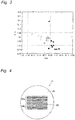
- Fig. 3 is a graph showing a relationship between the skewness Rsk and the kurtosis Rku of the carrier core materials in the examples and the comparative examples.
- the carrier core material was obtained.
- the carrier core material was obtained.
- the carrier core material was obtained.
- Fig. 1 shows an SEM photograph of the obtained carrier core material.
- the carrier core material was obtained.
- the carrier core material was obtained.
- the carrier core material was obtained.
- the carrier core material was obtained.
- the carrier core material was obtained.
- the carrier core material was obtained.
- the carrier core material was obtained.
- the carrier core material was obtained.
- the carrier core material was obtained.
- the carrier core material was obtained.
- Fig. 2 shows an SEM photograph of the obtained carrier core material.
- the carrier core material was obtained.
- the mixed slurry was sprayed with a spray drier into hot air of about 140°C (the number of revolutions of a disc was 20,000 rpm), and thus a dried granulated material having a particle diameter of 10 to 200 ⁇ m was obtained.
- the granulated material was temporarily calcined in the atmosphere at 950°C for 2 hours. Then, calcination was performed by the same method as in example 2, and thus the carrier core material was obtained.
- the carrier core material was obtained.
- the carrier core material was obtained.
- the apparent density of the carrier core material was measured according to JIS Z 2504.
- VSM room-temperature dedicated vibration sample type magnetometer
- the skewness Rsk, the kurtosis Rku and the maximum height Rz of the carrier core material were measured as follows.
- An ultra-deep color 3D shape measuring microscope ("VK-X100" made by Keyence Corporation) was used to observe the surface with a 100x objective lens, and thus the skewness Rsk, the kurtosis Rku and the maximum height Rz were determined.
- the carrier core material was first fixed to an adhesive tape whose surface was flat, a measurement view was determined with the 100x objective lens, thereafter an autofocus function was used to adjust a focal point to the surface of the adhesive tape and an auto-shooting function was used to capture the three-dimensional shape of the surface of the carrier core material.
- Fig. 4 shows a schematic view of the surface of the carrier core material taken out thereof.
- a line segment 23 whose length was 15.0 ⁇ m and which was extended in a horizontal direction was drawn, to each of the upper and lower portions thereof, 10 parallel lines at intervals of 0.75 ⁇ m were added and a total of 21 roughness curves on the line segment were taken.
- the 10 line segments 24a on the upper side and the 10 line segments 24b on the lower side are schematically shown.
- the carrier core material was formed substantially in the shape of a sphere, the roughness curve taken had a given curvature as a background. Hence, as the correction of the background, the optimal quadratic curve was fitted and was subtracted from the roughness curve. In this case, a cutoff value ⁇ s was set to 0.25 ⁇ m, and a cutoff value ⁇ c was set to 0.08 mm.
- Rn in mathematical formula 1 represents a difference from a mean line of the nth peak or trough in the reference length of 15 ⁇ m, and a root mean square height Rq is determined by a formula shown in mathematical formula 2 below.
- the skewness Rsk obtained indicates that as the value thereof is increased, a greater deviation to a region located in the trough is made.
- the kurtosis Rku of the carrier core material was also calculated.
- the kurtosis Rku was calculated by applying the roughness curve to a formula shown in mathematical formula 3 below.
- the kurtosis Rku obtained indicates that as the value thereof is increased, greater sharpness is made.
- the maximum height Rz was determined as the sum of the height of the highest peak and the depth of the deepest trough in the roughness curve.
- the average particle diameter of the carrier core material used for analysis was limited to a range of 32.0 to 34. 0 ⁇ m. As described above, the average particle diameter of the carrier core material which is the target to be measured is limited to a narrow range, and thus it is possible to reduce an error caused by a residue produced in curvature correction. As the average value of each parameter, the average value in 30 particles was used.
- the concentration of Cl in the carrier core material was measured by a silver nitrate titration method. Specifically, pure water was added to samples, and the samples were left and were thereafter filtered and washed. As an indicator, a phenolphthalein solution was used, and when the solution was acidic, NaHCO 3 was added to turn the solution red. The solution after the elution of Cl was titrated with an AgNO 3 solution, and thus the concentration of Cl in the carrier core material was measured.
- the two-component developers produced were put into a development device (the peripheral speed of a development roller Vs: 406 mm / sec, the peripheral speed of a photosensitive drum Vp: 205 mm / sec and a photosensitive drum-to-development roller distance: 0.3 mm), 1000 sheets with a blank image were printed and thereafter carrier scattering was evaluated with the following criteria. The results are shown in table 1.
- VSM room-temperature dedicated vibration sample type magnetometer
- the skewness Rsk was further increased, the kurtosis Rku was further decreased, carrier scattering occurred to some extent as in the carrier core material of comparative example 1 and a large amount of resin was used.
- the skewness Rsk was high, carrier scattering occurred to some extent and a smaller amount of resin than the conventional amount was used but satisfactory levels were not achieved.
- the kurtosis Rku was low, carrier scattering occurred to some extent and a smaller amount of resin than the conventional amount was used but satisfactory levels were not achieved.
- the skewness Rsk was high, the kurtosis Rku was low, carrier scattering occurred to some extent and the amount of resin used was equal to or more than the conventional amount.
- the skewness Rsk was high, the kurtosis Rku was low, carrier scattering occurred to some extent and the amount of resin used was equal to or more than the conventional amount.
- the skewness Rsk was high, the kurtosis Rku was low, carrier scattering occurred to some extent and a smaller amount of resin than the conventional amount was used but satisfactory levels were not achieved.
- a concave-convex shape formed in the surface thereof is a specific shape, and thus cracking or chipping is unlikely to occur, with the result that even when an image formation speed is increased, it is possible to maintain high image quality even in long-term use. It is also possible to reduce the amount of coating resin used without properties such as electrical resistance being lowered, and thus the carrier core material is useful.
Landscapes
- Physics & Mathematics (AREA)
- General Physics & Mathematics (AREA)
- Chemical & Material Sciences (AREA)
- Organic Chemistry (AREA)
- Crystallography & Structural Chemistry (AREA)
- Chemical Kinetics & Catalysis (AREA)
- Spectroscopy & Molecular Physics (AREA)
- Inorganic Chemistry (AREA)
- Developing Agents For Electrophotography (AREA)
Claims (3)
- Trägerkernmaterial, welches aus Ferritteilchen gebildet ist,wobei eine Asymmetrie Rsk des Teilchens gleich oder mehr als -0,40, aber gleich oder weniger als -0,20, gemessen gemäß der Beschreibung, ist,eine Kurtosis Rku des Teilchens gleich oder mehr als 3,20, aber gleich oder weniger als 3,50, gemessen gemäß der Beschreibung, ist,eine Maximalhöhe Rz des Teilchens gleich oder mehr als 2,20 µm, aber gleich oder weniger als 3,50 µm, wie in der Beschreibung beschrieben, ist,wobei die Ferritteilchen Teilchen sind, welche Sr enthalten und worin die Hauptzusammensetzung ein Mn-Ferrit, ein Mg-Ferrit oder ein MnMg-Ferrit ist.
- Elektrophotografischer Entwicklungsträger,
wobei eine Oberfläche des Trägerkernmaterials gemäß Anspruch 1 mit einem Harz beschichtet ist. - Elektrophotografischer Entwickler, umfassend:
den elektrophotografischen Entwicklungsträger gemäß Anspruch 2; und einen Toner.
Applications Claiming Priority (2)
| Application Number | Priority Date | Filing Date | Title |
|---|---|---|---|
| JP2016071103A JP6650324B2 (ja) | 2016-03-31 | 2016-03-31 | キャリア芯材並びにこれを用いた電子写真現像用キャリア及び電子写真用現像剤 |
| PCT/JP2017/012582 WO2017170512A1 (ja) | 2016-03-31 | 2017-03-28 | キャリア芯材並びにこれを用いた電子写真現像用キャリア及び電子写真用現像剤 |
Publications (3)
| Publication Number | Publication Date |
|---|---|
| EP3454130A1 EP3454130A1 (de) | 2019-03-13 |
| EP3454130A4 EP3454130A4 (de) | 2019-09-18 |
| EP3454130B1 true EP3454130B1 (de) | 2021-11-24 |
Family
ID=59965764
Family Applications (1)
| Application Number | Title | Priority Date | Filing Date |
|---|---|---|---|
| EP17775049.4A Active EP3454130B1 (de) | 2016-03-31 | 2017-03-28 | Trägerkernmaterial und elektrofotografischer entwicklungsträger und elektrofotografischer entwickler, in denen das besagte material verwendet wird |
Country Status (5)
| Country | Link |
|---|---|
| US (1) | US10698330B2 (de) |
| EP (1) | EP3454130B1 (de) |
| JP (1) | JP6650324B2 (de) |
| CN (1) | CN108885419B (de) |
| WO (1) | WO2017170512A1 (de) |
Families Citing this family (4)
| Publication number | Priority date | Publication date | Assignee | Title |
|---|---|---|---|---|
| JP7099902B2 (ja) * | 2018-08-07 | 2022-07-12 | Dowaエレクトロニクス株式会社 | キャリア芯材 |
| JP7275361B2 (ja) * | 2019-03-08 | 2023-05-17 | Dowaエレクトロニクス株式会社 | キャリア芯材並びにこれを用いた電子写真現像用キャリア及び電子写真用現像剤 |
| CN112113835A (zh) * | 2020-09-10 | 2020-12-22 | 北京理工大学 | 一种微动疲劳裂纹萌生位置判定方法 |
| JP7697866B2 (ja) * | 2021-10-22 | 2025-06-24 | Dowaエレクトロニクス株式会社 | キャリア芯材並びにこれを用いた電子写真現像用キャリア及び電子写真用現像剤 |
Family Cites Families (10)
| Publication number | Priority date | Publication date | Assignee | Title |
|---|---|---|---|---|
| CN100557726C (zh) * | 2003-11-12 | 2009-11-04 | 关东电化工业株式会社 | 镁基铁氧体、含有该铁氧体的电子照相显影载体以及含有该载体的显影剂 |
| JP4442482B2 (ja) * | 2005-03-23 | 2010-03-31 | コニカミノルタビジネステクノロジーズ株式会社 | 2成分現像剤、画像形成方法、画像形成装置 |
| JP4434060B2 (ja) * | 2005-03-29 | 2010-03-17 | コニカミノルタビジネステクノロジーズ株式会社 | 2成分現像剤、画像形成方法、画像形成装置 |
| JP4781015B2 (ja) * | 2005-06-03 | 2011-09-28 | パウダーテック株式会社 | 電子写真用フェライトキャリア芯材、電子写真用フェライトキャリア及びこれらの製造方法、並びに該フェライトキャリアを用いた電子写真用現像剤 |
| JP5377386B2 (ja) * | 2010-03-29 | 2013-12-25 | Dowaエレクトロニクス株式会社 | 電子写真現像剤用キャリア芯材、その製造方法、電子写真現像剤用キャリア、および電子写真現像剤 |
| US8722303B2 (en) * | 2011-08-31 | 2014-05-13 | Canon Kabushiki Kaisha | Image forming method |
| JP5650773B2 (ja) * | 2013-02-25 | 2015-01-07 | Dowaエレクトロニクス株式会社 | 電子写真現像剤用キャリア芯材の製造方法、電子写真現像剤用キャリア芯材、電子写真現像剤用キャリア、および電子写真現像剤 |
| JP5690367B2 (ja) * | 2013-03-29 | 2015-03-25 | Dowaエレクトロニクス株式会社 | 電子写真現像剤用キャリア芯材、その製造方法、電子写真現像剤用キャリア、および電子写真現像剤 |
| JP5715656B2 (ja) * | 2013-03-29 | 2015-05-13 | Dowaエレクトロニクス株式会社 | 電子写真現像剤用キャリア芯材、その製造方法、電子写真現像剤用キャリア、および電子写真現像剤 |
| JP5818380B2 (ja) * | 2013-11-25 | 2015-11-18 | Dowaエレクトロニクス株式会社 | フェライト粒子並びにそれを用いた電子写真現像用キャリア及び電子写真用現像剤 |
-
2016
- 2016-03-31 JP JP2016071103A patent/JP6650324B2/ja active Active
-
2017
- 2017-03-28 WO PCT/JP2017/012582 patent/WO2017170512A1/ja not_active Ceased
- 2017-03-28 EP EP17775049.4A patent/EP3454130B1/de active Active
- 2017-03-28 US US16/080,062 patent/US10698330B2/en active Active
- 2017-03-28 CN CN201780020988.XA patent/CN108885419B/zh active Active
Also Published As
| Publication number | Publication date |
|---|---|
| CN108885419A (zh) | 2018-11-23 |
| US20190064688A1 (en) | 2019-02-28 |
| EP3454130A1 (de) | 2019-03-13 |
| WO2017170512A1 (ja) | 2017-10-05 |
| CN108885419B (zh) | 2022-07-05 |
| JP2017181904A (ja) | 2017-10-05 |
| US10698330B2 (en) | 2020-06-30 |
| EP3454130A4 (de) | 2019-09-18 |
| JP6650324B2 (ja) | 2020-02-19 |
Similar Documents
| Publication | Publication Date | Title |
|---|---|---|
| EP3075710B1 (de) | Ferritteilchen, träger zur elektrofotografischen entwicklung damit sowie entwickler für die elektrofotografie | |
| US9268246B2 (en) | Method for manufacturing carrier core particles for electrophotographic developer, carrier core particles for electrophotographic developer, carrier for electrophotographic developer, and electrophotographic developer | |
| US9964878B2 (en) | Carrier core material and electrophotographic development carrier using same and electrophotographic developer | |
| US10088764B2 (en) | Carrier core material and electrophotographic development carrier using same and electrophotographic developer | |
| EP3454130A1 (de) | Trägerkernmaterial und elektrofotografischer entwicklungsträger und elektrofotografischer entwickler, in dem das besagte material verwendet wird | |
| JP2016025288A (ja) | フェライト磁性材 | |
| US20180107129A1 (en) | Carrier core material and electrophotographic development carrier using same and electrophotographic developer | |
| US9507285B2 (en) | Ferrite particles and electrophotographic development carrier using same, electrophotographic developer and method of manufacturing ferrite particles | |
| EP3605237B1 (de) | Trägerkernmaterial und elektrophotographischer träger und elektrophotographischer entwickler, die trägerkernmaterial verwenden | |
| JP5858591B2 (ja) | キャリア芯材並びにそれを用いた電子写真用キャリア及び電子写真用現像剤 | |
| JP2015227268A (ja) | フェライト粒子並びにそれを用いた電子写真用キャリア及び電子写真用現像剤 | |
| JP5769350B1 (ja) | フェライト粒子並びにそれを用いた電子写真現像用キャリア及び電子写真用現像剤 | |
| JP2017031031A (ja) | フェライト粒子並びにそれを用いた電子写真現像用キャリア及び電子写真用現像剤 | |
| EP2891925B1 (de) | Trägerkernmaterial für einen elektrofotografischen entwickler, träger für einen elektrofotografischen entwickler und elektrofotografischer entwickler | |
| EP4036654A1 (de) | Trägerkernmaterial und elektrofotografischer entwicklungsträger und elektrofotografischer entwickler, in dem das besagte material verwendet wird | |
| JP6916727B2 (ja) | キャリア芯材 | |
| EP4130885A1 (de) | Ferritteilchen, kernmaterial für elektrofotografischen entwicklerträger, elektrofotografischer entwicklerträger und elektrofotografischer entwickler |
Legal Events
| Date | Code | Title | Description |
|---|---|---|---|
| STAA | Information on the status of an ep patent application or granted ep patent |
Free format text: STATUS: THE INTERNATIONAL PUBLICATION HAS BEEN MADE |
|
| PUAI | Public reference made under article 153(3) epc to a published international application that has entered the european phase |
Free format text: ORIGINAL CODE: 0009012 |
|
| STAA | Information on the status of an ep patent application or granted ep patent |
Free format text: STATUS: REQUEST FOR EXAMINATION WAS MADE |
|
| PUAB | Information related to the publication of an a document modified or deleted |
Free format text: ORIGINAL CODE: 0009199EPPU |
|
| PUAI | Public reference made under article 153(3) epc to a published international application that has entered the european phase |
Free format text: ORIGINAL CODE: 0009012 |
|
| 17P | Request for examination filed |
Effective date: 20181011 |
|
| AK | Designated contracting states |
Kind code of ref document: A1 Designated state(s): AL AT BE BG CH CY CZ DE DK EE ES FI FR GB GR HR HU IE IS IT LI LT LU LV MC MK MT NL NO PL PT RO RS SE SI SK SM TR |
|
| AX | Request for extension of the european patent |
Extension state: BA ME |
|
| DAV | Request for validation of the european patent (deleted) | ||
| DAX | Request for extension of the european patent (deleted) | ||
| REG | Reference to a national code |
Ref country code: DE Ref legal event code: R079 Ref document number: 602017049832 Country of ref document: DE Free format text: PREVIOUS MAIN CLASS: G03G0009107000 Ipc: G03G0009100000 |
|
| A4 | Supplementary search report drawn up and despatched |
Effective date: 20190820 |
|
| RIC1 | Information provided on ipc code assigned before grant |
Ipc: G03G 9/113 20060101ALI20190813BHEP Ipc: G03G 9/107 20060101ALI20190813BHEP Ipc: G03G 9/10 20060101AFI20190813BHEP |
|
| GRAP | Despatch of communication of intention to grant a patent |
Free format text: ORIGINAL CODE: EPIDOSNIGR1 |
|
| STAA | Information on the status of an ep patent application or granted ep patent |
Free format text: STATUS: GRANT OF PATENT IS INTENDED |
|
| INTG | Intention to grant announced |
Effective date: 20210720 |
|
| RIN1 | Information on inventor provided before grant (corrected) |
Inventor name: KITAHARA, YUKI Inventor name: OGAWA, SHOU |
|
| GRAS | Grant fee paid |
Free format text: ORIGINAL CODE: EPIDOSNIGR3 |
|
| GRAA | (expected) grant |
Free format text: ORIGINAL CODE: 0009210 |
|
| STAA | Information on the status of an ep patent application or granted ep patent |
Free format text: STATUS: THE PATENT HAS BEEN GRANTED |
|
| AK | Designated contracting states |
Kind code of ref document: B1 Designated state(s): AL AT BE BG CH CY CZ DE DK EE ES FI FR GB GR HR HU IE IS IT LI LT LU LV MC MK MT NL NO PL PT RO RS SE SI SK SM TR |
|
| REG | Reference to a national code |
Ref country code: GB Ref legal event code: FG4D |
|
| REG | Reference to a national code |
Ref country code: AT Ref legal event code: REF Ref document number: 1450309 Country of ref document: AT Kind code of ref document: T Effective date: 20211215 |
|
| REG | Reference to a national code |
Ref country code: DE Ref legal event code: R096 Ref document number: 602017049832 Country of ref document: DE |
|
| REG | Reference to a national code |
Ref country code: IE Ref legal event code: FG4D |
|
| REG | Reference to a national code |
Ref country code: LT Ref legal event code: MG9D |
|
| REG | Reference to a national code |
Ref country code: NL Ref legal event code: MP Effective date: 20211124 |
|
| REG | Reference to a national code |
Ref country code: AT Ref legal event code: MK05 Ref document number: 1450309 Country of ref document: AT Kind code of ref document: T Effective date: 20211124 |
|
| PG25 | Lapsed in a contracting state [announced via postgrant information from national office to epo] |
Ref country code: RS Free format text: LAPSE BECAUSE OF FAILURE TO SUBMIT A TRANSLATION OF THE DESCRIPTION OR TO PAY THE FEE WITHIN THE PRESCRIBED TIME-LIMIT Effective date: 20211124 Ref country code: LT Free format text: LAPSE BECAUSE OF FAILURE TO SUBMIT A TRANSLATION OF THE DESCRIPTION OR TO PAY THE FEE WITHIN THE PRESCRIBED TIME-LIMIT Effective date: 20211124 Ref country code: FI Free format text: LAPSE BECAUSE OF FAILURE TO SUBMIT A TRANSLATION OF THE DESCRIPTION OR TO PAY THE FEE WITHIN THE PRESCRIBED TIME-LIMIT Effective date: 20211124 Ref country code: BG Free format text: LAPSE BECAUSE OF FAILURE TO SUBMIT A TRANSLATION OF THE DESCRIPTION OR TO PAY THE FEE WITHIN THE PRESCRIBED TIME-LIMIT Effective date: 20220224 Ref country code: AT Free format text: LAPSE BECAUSE OF FAILURE TO SUBMIT A TRANSLATION OF THE DESCRIPTION OR TO PAY THE FEE WITHIN THE PRESCRIBED TIME-LIMIT Effective date: 20211124 |
|
| PG25 | Lapsed in a contracting state [announced via postgrant information from national office to epo] |
Ref country code: IS Free format text: LAPSE BECAUSE OF FAILURE TO SUBMIT A TRANSLATION OF THE DESCRIPTION OR TO PAY THE FEE WITHIN THE PRESCRIBED TIME-LIMIT Effective date: 20220324 Ref country code: SE Free format text: LAPSE BECAUSE OF FAILURE TO SUBMIT A TRANSLATION OF THE DESCRIPTION OR TO PAY THE FEE WITHIN THE PRESCRIBED TIME-LIMIT Effective date: 20211124 Ref country code: PT Free format text: LAPSE BECAUSE OF FAILURE TO SUBMIT A TRANSLATION OF THE DESCRIPTION OR TO PAY THE FEE WITHIN THE PRESCRIBED TIME-LIMIT Effective date: 20220324 Ref country code: PL Free format text: LAPSE BECAUSE OF FAILURE TO SUBMIT A TRANSLATION OF THE DESCRIPTION OR TO PAY THE FEE WITHIN THE PRESCRIBED TIME-LIMIT Effective date: 20211124 Ref country code: NO Free format text: LAPSE BECAUSE OF FAILURE TO SUBMIT A TRANSLATION OF THE DESCRIPTION OR TO PAY THE FEE WITHIN THE PRESCRIBED TIME-LIMIT Effective date: 20220224 Ref country code: NL Free format text: LAPSE BECAUSE OF FAILURE TO SUBMIT A TRANSLATION OF THE DESCRIPTION OR TO PAY THE FEE WITHIN THE PRESCRIBED TIME-LIMIT Effective date: 20211124 Ref country code: LV Free format text: LAPSE BECAUSE OF FAILURE TO SUBMIT A TRANSLATION OF THE DESCRIPTION OR TO PAY THE FEE WITHIN THE PRESCRIBED TIME-LIMIT Effective date: 20211124 Ref country code: HR Free format text: LAPSE BECAUSE OF FAILURE TO SUBMIT A TRANSLATION OF THE DESCRIPTION OR TO PAY THE FEE WITHIN THE PRESCRIBED TIME-LIMIT Effective date: 20211124 Ref country code: GR Free format text: LAPSE BECAUSE OF FAILURE TO SUBMIT A TRANSLATION OF THE DESCRIPTION OR TO PAY THE FEE WITHIN THE PRESCRIBED TIME-LIMIT Effective date: 20220225 Ref country code: ES Free format text: LAPSE BECAUSE OF FAILURE TO SUBMIT A TRANSLATION OF THE DESCRIPTION OR TO PAY THE FEE WITHIN THE PRESCRIBED TIME-LIMIT Effective date: 20211124 |
|
| PG25 | Lapsed in a contracting state [announced via postgrant information from national office to epo] |
Ref country code: SM Free format text: LAPSE BECAUSE OF FAILURE TO SUBMIT A TRANSLATION OF THE DESCRIPTION OR TO PAY THE FEE WITHIN THE PRESCRIBED TIME-LIMIT Effective date: 20211124 Ref country code: SK Free format text: LAPSE BECAUSE OF FAILURE TO SUBMIT A TRANSLATION OF THE DESCRIPTION OR TO PAY THE FEE WITHIN THE PRESCRIBED TIME-LIMIT Effective date: 20211124 Ref country code: RO Free format text: LAPSE BECAUSE OF FAILURE TO SUBMIT A TRANSLATION OF THE DESCRIPTION OR TO PAY THE FEE WITHIN THE PRESCRIBED TIME-LIMIT Effective date: 20211124 Ref country code: EE Free format text: LAPSE BECAUSE OF FAILURE TO SUBMIT A TRANSLATION OF THE DESCRIPTION OR TO PAY THE FEE WITHIN THE PRESCRIBED TIME-LIMIT Effective date: 20211124 Ref country code: DK Free format text: LAPSE BECAUSE OF FAILURE TO SUBMIT A TRANSLATION OF THE DESCRIPTION OR TO PAY THE FEE WITHIN THE PRESCRIBED TIME-LIMIT Effective date: 20211124 Ref country code: CZ Free format text: LAPSE BECAUSE OF FAILURE TO SUBMIT A TRANSLATION OF THE DESCRIPTION OR TO PAY THE FEE WITHIN THE PRESCRIBED TIME-LIMIT Effective date: 20211124 |
|
| REG | Reference to a national code |
Ref country code: DE Ref legal event code: R097 Ref document number: 602017049832 Country of ref document: DE |
|
| PLBE | No opposition filed within time limit |
Free format text: ORIGINAL CODE: 0009261 |
|
| STAA | Information on the status of an ep patent application or granted ep patent |
Free format text: STATUS: NO OPPOSITION FILED WITHIN TIME LIMIT |
|
| PG25 | Lapsed in a contracting state [announced via postgrant information from national office to epo] |
Ref country code: MC Free format text: LAPSE BECAUSE OF FAILURE TO SUBMIT A TRANSLATION OF THE DESCRIPTION OR TO PAY THE FEE WITHIN THE PRESCRIBED TIME-LIMIT Effective date: 20211124 Ref country code: AL Free format text: LAPSE BECAUSE OF FAILURE TO SUBMIT A TRANSLATION OF THE DESCRIPTION OR TO PAY THE FEE WITHIN THE PRESCRIBED TIME-LIMIT Effective date: 20211124 |
|
| REG | Reference to a national code |
Ref country code: CH Ref legal event code: PL |
|
| 26N | No opposition filed |
Effective date: 20220825 |
|
| GBPC | Gb: european patent ceased through non-payment of renewal fee |
Effective date: 20220328 |
|
| PG25 | Lapsed in a contracting state [announced via postgrant information from national office to epo] |
Ref country code: SI Free format text: LAPSE BECAUSE OF FAILURE TO SUBMIT A TRANSLATION OF THE DESCRIPTION OR TO PAY THE FEE WITHIN THE PRESCRIBED TIME-LIMIT Effective date: 20211124 |
|
| REG | Reference to a national code |
Ref country code: BE Ref legal event code: MM Effective date: 20220331 |
|
| PG25 | Lapsed in a contracting state [announced via postgrant information from national office to epo] |
Ref country code: LU Free format text: LAPSE BECAUSE OF NON-PAYMENT OF DUE FEES Effective date: 20220328 Ref country code: LI Free format text: LAPSE BECAUSE OF NON-PAYMENT OF DUE FEES Effective date: 20220331 Ref country code: IE Free format text: LAPSE BECAUSE OF NON-PAYMENT OF DUE FEES Effective date: 20220328 Ref country code: GB Free format text: LAPSE BECAUSE OF NON-PAYMENT OF DUE FEES Effective date: 20220328 Ref country code: CH Free format text: LAPSE BECAUSE OF NON-PAYMENT OF DUE FEES Effective date: 20220331 |
|
| PG25 | Lapsed in a contracting state [announced via postgrant information from national office to epo] |
Ref country code: BE Free format text: LAPSE BECAUSE OF NON-PAYMENT OF DUE FEES Effective date: 20220331 |
|
| PG25 | Lapsed in a contracting state [announced via postgrant information from national office to epo] |
Ref country code: IT Free format text: LAPSE BECAUSE OF FAILURE TO SUBMIT A TRANSLATION OF THE DESCRIPTION OR TO PAY THE FEE WITHIN THE PRESCRIBED TIME-LIMIT Effective date: 20211124 |
|
| PG25 | Lapsed in a contracting state [announced via postgrant information from national office to epo] |
Ref country code: HU Free format text: LAPSE BECAUSE OF FAILURE TO SUBMIT A TRANSLATION OF THE DESCRIPTION OR TO PAY THE FEE WITHIN THE PRESCRIBED TIME-LIMIT; INVALID AB INITIO Effective date: 20170328 |
|
| PG25 | Lapsed in a contracting state [announced via postgrant information from national office to epo] |
Ref country code: MK Free format text: LAPSE BECAUSE OF FAILURE TO SUBMIT A TRANSLATION OF THE DESCRIPTION OR TO PAY THE FEE WITHIN THE PRESCRIBED TIME-LIMIT Effective date: 20211124 Ref country code: CY Free format text: LAPSE BECAUSE OF FAILURE TO SUBMIT A TRANSLATION OF THE DESCRIPTION OR TO PAY THE FEE WITHIN THE PRESCRIBED TIME-LIMIT Effective date: 20211124 |
|
| PG25 | Lapsed in a contracting state [announced via postgrant information from national office to epo] |
Ref country code: TR Free format text: LAPSE BECAUSE OF FAILURE TO SUBMIT A TRANSLATION OF THE DESCRIPTION OR TO PAY THE FEE WITHIN THE PRESCRIBED TIME-LIMIT Effective date: 20211124 |
|
| PG25 | Lapsed in a contracting state [announced via postgrant information from national office to epo] |
Ref country code: MT Free format text: LAPSE BECAUSE OF FAILURE TO SUBMIT A TRANSLATION OF THE DESCRIPTION OR TO PAY THE FEE WITHIN THE PRESCRIBED TIME-LIMIT Effective date: 20211124 |
|
| PGFP | Annual fee paid to national office [announced via postgrant information from national office to epo] |
Ref country code: DE Payment date: 20260204 Year of fee payment: 10 |
|
| PGFP | Annual fee paid to national office [announced via postgrant information from national office to epo] |
Ref country code: FR Payment date: 20260209 Year of fee payment: 10 |