EP3453258B1 - Streuvorrichtung für eine Teigbearbeitungsanlage - Google Patents
Streuvorrichtung für eine Teigbearbeitungsanlage Download PDFInfo
- Publication number
- EP3453258B1 EP3453258B1 EP18190902.9A EP18190902A EP3453258B1 EP 3453258 B1 EP3453258 B1 EP 3453258B1 EP 18190902 A EP18190902 A EP 18190902A EP 3453258 B1 EP3453258 B1 EP 3453258B1
- Authority
- EP
- European Patent Office
- Prior art keywords
- spreading
- storage container
- conveying screw
- screw
- return
- Prior art date
- Legal status (The legal status is an assumption and is not a legal conclusion. Google has not performed a legal analysis and makes no representation as to the accuracy of the status listed.)
- Active
Links
Images


Classifications
-
- A—HUMAN NECESSITIES
- A21—BAKING; EDIBLE DOUGHS
- A21C—MACHINES OR EQUIPMENT FOR MAKING OR PROCESSING DOUGHS; HANDLING BAKED ARTICLES MADE FROM DOUGH
- A21C9/00—Other apparatus for handling dough or dough pieces
- A21C9/04—Apparatus for spreading granular material on, or sweeping or coating the surfaces of, pieces or sheets of dough
Definitions
- the invention relates to a spreading device for a dough processing plant according to the preamble of claim 1.
- dough or strips of dough are sprinkled with scattering material during the manufacturing process.
- the sprinkling can also take place in such a way that a base is first sprinkled with grit, and then the dough or the dough band is placed on the base sprinkled with grit.
- Generic spreading devices are for example from the DE 34 26 974 C2 or the DE 697 20 325 T2 known. What these spreading devices have in common is the use of a rotationally driven spreading roller which is arranged below a spreading material housing that can be filled with spreading material. By dispensing grit from the grit housing, the grit exits downwards and is thereby transferred to an upward-facing surface section of the rotating spreading roller.
- the spreading material picked up on the upper side of the spreading roller is then conveyed further and then falls under the influence of gravity and, if necessary, with the aid of a scraper brush on a downward-facing surface section onto the dough underneath or the underlay that receives the dough.
- the transport of the spreading material within the spreading device takes place predominantly under the influence of gravity, so that the spreading material housing must be arranged accordingly above the rotatingly drivable spreading roller.
- the disadvantage of the known spreading devices is their relatively large overall height. Because in order to be able to accommodate a sufficient supply of grit in the grit housing, it must have a corresponding height. However, this relatively large overall height of the known spreading devices makes it particularly difficult to install the spreading devices between dough conveying devices, such as conveyor belts, arranged one above the other. As a result, it is therefore unavoidable in the known spreading devices, when arranged between several dough conveying devices provided one above the other, to use correspondingly small spreading material housings, so that frequent refilling of the spreading material supply in the spreading material housing is necessary.
- a device for applying seasonings and sweeteners to food which comprises a conveyor device and an applicator.
- the substances to be applied are conveyed from the conveying device to the applicator by a screw conveyor.
- the object of the present invention is to propose a new scattering device for a dough processing plant which avoids the disadvantages of the known prior art.
- the spreading device comprises, in addition to the grit housing of the generic type, an additional storage container for receiving a supply of grit.
- This storage container has an output opening at which the grit, in particular flour, can be removed from the storage container.
- the storage container is arranged to the side of the spreading roller. The lateral offset of the storage container to the spreading roller makes it possible for the storage container to be arranged next to the spreading roller or the spreading material housing, and any existing dough transport devices, for example conveyor belts, to be able to be guided past the storage container.
- the spreading device comprises a transverse conveying device which conveys the spreading material from the output opening of the storage container to the spreading material housing.
- the transverse conveying device By using the transverse conveying device, the spreading material is conveyed in the spreading device not only primarily through the influence of gravity, but also through corresponding conveying movements in the horizontal direction.
- the grit is conveyed from the storage container into the grit housing with the transverse conveyor. It is of course necessary that there is a supply of grit in the grit housing so that a sufficient amount of grit can fall down through the output openings onto the surface of the spreading roller at any time.
- the spreading devices known from the prior art use a sensor system with which the filling level of the spreading material in the spreading material housing can be monitored. If the fill level falls below a specified level, the sensors activate a conveyor device in order to replenish the spreading material. But this has the disadvantage that a complex and fault-prone sensors are required.
- the conveying device must be driven with its own drive independently of the other functional elements of the spreading device, since the conveying device has to be switched on and off depending on the fill level of the grit in the grit housing.
- the invention also provides a return device in the grit housing with which the grit can be conveyed back from the grit housing into the storage container.
- the transverse conveying device and the return conveying device result in a grit conveying device with which the grit can be conveyed in a cycle through the storage container and the grit housing.
- This circulation of the grit also prevents dead zones in which the grit remains for a long time, which is particularly advantageous if the output openings of the grit housing can be made smaller by means of slides.
- the dispensing opening of the storage container is arranged laterally above the end of the spreading roller.
- the type of construction of the transverse conveyor device is basically arbitrary. In order to enable the most effective possible conveying movement of the grit from the storage container into the grit housing, it is particularly advantageous if the transverse conveying device conveys the grit from the output opening parallel to the scattering roller through the grit housing. In this case, the grit carries out a purely horizontally aligned conveying movement through the grit housing from the dispensing opening of the storage container.
- the way in which the transverse conveying device is constructed is basically also arbitrary.
- the spreading device according to the invention can be implemented in a particularly simple and cost-effective manner if the cross conveyor device is designed in the manner of a rotationally drivable cross conveyor screw.
- the return conveyor device can also be designed in a particularly simple and cost-effective manner in the manner of a rotationally drivable return conveyor screw.
- the return screw is arranged parallel to the transverse screw conveyor.
- the way in which the transverse screw conveyor or the return screw is mounted in the grit housing is basically arbitrary.
- the two screw conveyors are rotatably mounted on the wall of the grit housing.
- the return screw and / or the transverse screw are made of food-safe plastic.
- an agitator can also be arranged in the storage container, with which the spreading material is stirred in the storage container. It is particularly advantageous if the agitator is fastened in a rotationally fixed manner to the end of the transverse screw conveyor facing the storage container. Then the agitator can also be driven simply by driving the transverse screw conveyor.
- the grit conveyed by the transverse screw conveyor must be deflected in the direction of the return screw conveyor.
- the screw thread at the end of the return screw facing away from the storage container protrudes over the screw thread at the end of the transverse screw conveyor facing away from the storage container. This protrusion of the worm thread on the return worm compared to the worm thread on the cross worm creates a deflection zone in which the grit can be easily deflected from the cross worm to the worm back.
- transverse conveyor screw and the return conveyor screw are driven by a common drive motor.
- the gearing for driving the two screw conveyors by means of a common drive motor is advantageously designed in such a way that the two screw conveyors are driven with opposite angles of rotation. In this way, the screw threads of the two conveyor screws can be formed with the same helix angle.
- Fig. 1 shows a spreading device 01 in a perspective side view.
- the spreading device comprises a spreading material housing 02 with a spreading roller 03 arranged underneath (see Fig. 2 ) and a storage container 04 arranged to the side of the grit housing.
- the drive 05 of the spreading device 01 is in turn arranged to the side of the storage container 04.
- the function of the spreading device 01 will be explained in more detail below.
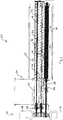
- Fig. 2 shows the spreading device 01 with the grit housing 02, the storage container 04 and the drive 05 in longitudinal section.
- a desired amount of grit, in particular flour, can be received in the interior of the storage container 04.
- the grit is in Fig. 2 not shown so as not to cover the components of the spreading device 01.
- the grit stored in the storage container 04 slides downward under the influence of gravity in the direction of a transverse conveying device 06, which is designed in the manner of a transverse screw conveyor 07.
- the transverse screw conveyor 07 By rotationally driving the transverse screw conveyor 07 by means of the drive motor 08, which acts via a gear 09, the grit is conveyed from the storage container 04 through an output opening 10 into the interior of the grit housing 02.
- the transverse screw conveyor 07 extends parallel to the spreading roller 03 through the grit housing so that the grit can be conveyed through the grit housing 02 in the transverse conveying direction 11.
- the grit thus conveyed into the grit housing 02 falls through an output opening 12 (see Fig. 3 ) onto the spreading roller below 03.
- the spreading material can then be spread onto a strip of dough 14 which is conveyed through under the spreading roller 03 by means of a conveyor belt 15.
- the transverse screw conveyor 07 At the end of the transverse screw conveyor 07 pointing away from the storage container 04 there is a deflection zone 16 in which the grit conveyed by the transverse screw conveyor 07 is deflected upward in the direction of a return conveyor 17.
- the grit is thus removed from the storage container 04 by driving the transverse screw 07 and the return screw 18 conveyed through the grit housing 02 in a circuit.
- an agitator 20 is provided in the storage container 04 above the transverse screw conveyor 07, which is rotatably connected to the return screw conveyor 18 and can thus also be driven by the drive motor 08 and via the transmission 09.
- a further conveyor belt 21 for example, can be provided directly above the spreading material housing 02, on which a strip of dough 22 can be conveyed.
- the spreading device 01 has a very low overall height in the area of the spreading material housing 02, so that a relatively small distance between the conveyor belts 15 and 21 can be realized.
- Both screw conveyors 07 and 18 are made of food-safe plastic.
- Fig. 3 shows the spreading device 01 with the spreading roller 03, the transverse screw conveyor 07 and the return screw 18 in cross section.
- the transverse screw conveyor 07 and the return screw 18 are mounted in the wall 23 which surrounds the circumference of the two screw conveyors 07 and 18. With slides 24 the output opening 12, at which the spreading material is transferred to the spreading roller 03 underneath, can be enlarged or reduced in its cross section.
Landscapes
- Life Sciences & Earth Sciences (AREA)
- Engineering & Computer Science (AREA)
- Food Science & Technology (AREA)
- Formation And Processing Of Food Products (AREA)
- Manufacturing And Processing Devices For Dough (AREA)
Description
- Die Erfindung betrifft eine Streuvorrichtung für eine Teigbearbeitungsanlage nach dem Oberbegriff des Anspruchs 1.
- Bei verschiedensten Herstellungsprozessen in der Lebensmittelindustrie ist es erforderlich, dass Teig bzw. Teigbänder während des Herstellungs-prozesses mit Streugut bestreut werden. Das Bestreuen kann dabei auch in der Weise erfolgen, dass zunächst eine Unterlage mit Streugut bestreut wird, und anschließend der Teig oder das Teigband auf die mit Streugut bestreute Unterlage aufgelegt wird. Gattungsgemäße Streuvor-richtungen sind beispielsweise aus der
DE 34 26 974 C2 oder derDE 697 20 325 T2 bekannt. Gemeinsam ist diesen Streuvorrichtungen die Verwendung einer rotatorisch angetriebenen Streuwalze, die unterhalb eines mit Streugut befüllbaren Streugutgehäuses angeordnet ist. Durch Ausgabe von Streugut aus dem Streugutgehäuse tritt das Streugut unter Schwerkraft nach unten aus und wird dadurch auf einen nach oben weisenden Oberflächenabschnitt der rotierenden Streuwalze übertragen. Durch den rotatorischen Antrieb der Streuwalze wird das an der Ober-seite der Streuwalze aufgenommene Streugut dann weiter gefördert und fällt unter Schwerkrafteinfluss und gegebenenfalls unter Zuhilfenahme einer Abstreifbürste anschließend an einem nach unten weisenden Oberflächenabschnitt auf den darunter befindlichen Teig bzw. die den Teig aufnehmende Unterlage. Der Transport des Streuguts innerhalb der Streuvorrichtung erfolgt überwiegend unter Schwerkrafteinfluss, so dass das Streugutgehäuse entsprechend oberhalb der rotatorisch antreibbaren Streuwalze angeordnet sein muss. - Nachteilig an den bekannten Streuvorrichtungen ist deren relativ große Bauhöhe. Denn um einen ausreichenden Vorrat an Streugut in dem Streugutgehäuse aufnehmen zu können, muss dieses eine entsprechende Höhe aufweisen. Diese relativ große Bauhöhe der bekannten Streuvorrichtungen erschwert aber insbesondere den Einbau der Streuvorrichtungen zwischen übereinander angeordneten Teigfördereinrichtungen, wie beispielsweise Förderbändern. Im Ergebnis ist es deshalb bei den bekannten Streuvorrichtungen bei Anordnung zwischen mehreren übereinander vorgesehenen Teigfördereinrichtungen unumgänglich, entsprechend kleine Streugutgehäuse zu verwenden, so dass ein häufiges Auffüllen des Streugutvorrats in dem Streugutgehäuse erforderlich ist.
- Aus der
US 2014/326758 A1 ist eine Vorrichtung zum Aufbringen von Würz- und Süßungsmitteln auf Lebensmittel bekannt, die eine Fördereinrichtung und einen Applikator umfasst. Die aufzubringenden Substanzen werden durch eine Förderschnecke von der Fördervorrichtung zu dem Applikator gefördert. - Ausgehend von diesem Stand der Technik ist es Aufgabe der vorliegenden Erfindung, eine neue Streuvorrichtung für eine Teigbearbeitungsanlage vorzuschlagen, die die Nachteile des vorbekannten Stands der Technik vermeidet.
- Diese Aufgabe wird durch eine Streuvorrichtung nach der Lehre des Anspruchs 1 gelöst.
- Vorteilhafte Ausführungsformen der Erfindung sind Gegenstand der Unteransprüche.
- Die Erfindung beruht auf dem Grundgedanken, dass die Streuvorrichtung neben dem gattungsgemäß vorhandenen Streugutgehäuse einen zusätzlichen Vorratsbehälter zur Aufnahme eines Streugutvorrats umfasst. Dieser Vorratsbehälter weist dabei eine Ausgabeöffnung auf, an der das Streugut, insbesondere Mehl, aus dem Vorratsbehälter entnommen werden kann. Erfindungsgemäß ist der Vorratsbehälter seitlich der Streuwalze angeordnet. Durch den seitlichen Versatz des Vorratsbehälters zur Streuwalze wird es möglich, dass der Vorratsbehälter neben der Streuwalze bzw. dem Streugutgehäuse angeordnet wird, und gegebenenfalls vorhandene Teigtransporteinrichtungen, beispielsweise Förderbänder, seitlich des Vorratsbehältnisses vorbeigeführt werden können. Um das Streugut aus dem Vorratsbehälter in die Streuvorrichtung fördern zu können, umfasst die erfindungsgemäße Streuvorrichtung eine Querfördereinrichtung, die das Streugut von der Ausgabeöffnung des Vorratsbehälters zum Streugutgehäuse fördert. Durch die Verwendung der Querfördereinrichtung erfolgt die Förderung des Streuguts in der Streuvorrichtung also nicht nur primär nur durch Schwerkrafteinfluss, sondern zusätzlich auch durch entsprechende Förderbewegungen in Horizontalrichtung.
- Erfindungsgemäß wird das Streugut mit der Querfördereinrichtung vom Vorratsbehälter in das Streugutgehäuse eingefördert. Dabei ist es selbstverständlich notwendig, dass im Streugutgehäuse ein Streugutvorrat vorhanden ist, so dass jederzeit eine ausreichende Menge Streugut durch die Ausgabeöffnungen nach unten auf die Oberfläche der Streuwalze fallen kann. Um dies zu gewährleisten, wird bei den aus dem Stand der Technik bekannten Streuvorrichtungen eine Sensorik eingesetzt, mit der der Füllstand des Streuguts im Streugutgehäuse überwacht werden kann. Unterschreitet der Füllstand ein vorgegebenes Niveau, wird durch die Sensorik eine Fördereinrichtung aktiviert, um Streugut nachzufördern. Dies hat aber den Nachteil, dass eine aufwendige und störanfällige Sensorik erforderlich ist. Außerdem muss die Fördereinrichtung mit einem eigenen Antrieb unabhängig von den sonstigen Funktionselementen der Streuvorrichtung angetrieben werden, da die Fördereinrichtung abhängig vom Füllstand des Streuguts im Streugutgehäuse ein- und abgeschaltet werden muss.
- Um eine Überfüllung des Streugutgehäuses trotz der Förderbewegung der Querfördereinrichtung und ohne Einsatz einer Sensorik zur Überwachung des Füllstandes auszuschließen, sieht die Erfindung vor, im Streugutgehäuse zusätzlich auch eine Rückfördereinrichtung, mit der das Streugut aus dem Streugutgehäuse zurück in den Vorratsbehälter gefördert werden kann. Im Ergebnis ergeben die Querfördereinrichtung und die Rückfördereinrichtung auf diese Weise eine Streugutfördereinrichtung, mit der das Streugut durch den Vorratsbehälter und das Streugutgehäuse im Kreislauf gefördert werden kann. Durch diese Kreislaufförderung des Streuguts werden außerdem Totzonen, in denen das Streugut längere Zeit verweilt, vermieden, was insbesondere von Vorteil ist, wenn die Ausgabeöffnungen des Streugutgehäuses mittels Schiebern verkleinert werden können.
- Um eine möglichst platzsparende und flache Streuvorrichtung zu erhalten, ist es besonders vorteilhaft, wenn die Ausgabeöffnung des Vorratsbehälters seitlich über dem Ende der Streuwalze angeordnet ist.
- In welcher Bauart die Querfördereinrichtung ausgebildet ist, ist grundsätzlich beliebig. Um eine möglichst effektive Förderbewegung des Streuguts von dem Vorratsbehälter in das Streugutgehäuse zu ermöglichen, ist es besonders vorteilhaft, wenn die Querfördereinrichtung das Streugut von der Ausgabeöffnung parallel zur Streuwalze durch das Streugutgehäuse fördert. In diesem Fall führt das Streugut also von der Ausgabeöffnung des Vorratsbehälters eine rein horizontal ausgerichtete Förderbewegung durch das Streugutgehäuse aus.
- In welcher Weise die Querfördereinrichtung konstruktiv ausgebildet ist, ist grundsätzlich ebenfalls beliebig. Besonders einfach und kostengünstig kann die erfindungsgemäße Streuvorrichtung realisiert werden, wenn die Querfördereinrichtung in der Art einer rotatorisch antreibbaren Querförderschnecke ausgebildet ist.
- Auch die Rückfördereinrichtung kann besonders einfach und kostengünstig in der Art einer rotatorisch antreibbaren Rückförderschnecke ausgebildet sein.
- Um einen möglichst widerstandsfreien Streugutförderumlauf mittels der Querförderschnecke und der Rückförderschnecke zu ermöglichen, ist es besonders vorteilhaft, wenn die Rückförderschnecke parallel zur Querförderschnecke angeordnet ist.
- In welcher Weise die Querförderschnecke bzw. die Rückförderschnecke im Streugutgehäuse gelagert ist, ist grundsätzlich beliebig. Um eine möglichst einfache Lagerung der beiden Förderschnecken zu gewährleisten und zugleich eine effektive Förderung des Streuguts entlang der rotierenden Förderschnecken zu ermöglichen, ist es besonders vorteilhaft, wenn die beiden Förderschnecken an der Wandung des Streugutgehäuses drehbar gelagert sind. Dies bedeutet mit anderen Worten, dass Abschnitte der Wandung des Streugutgehäuses entsprechend dem Umfang der beiden Förderschnecken ausgebildet sind. Durch das Umgreifen der beiden Förderschnecken durch die Wandung des Streugutgehäuses wird eine hohe Effektivität bei der Streugutförderung entlang der beiden rotierenden Förderschnecken erreicht.
- Im Hinblick auf die Lebensmittelsicherheit ist es besonders vorteilhaft, wenn die Rückförderschnecke und/oder die Querförderschnecke aus lebensmittelechtem Kunststoff hergestellt sind.
- Um das Nachrutschen des Streuguts im Vorratsbehälter in Richtung der Querfördereinrichtung zu erleichtern, kann im Vorratsbehälter zusätzlich ein Rührwerk angeordnet sein, mit dem das Streugut im Vorratsbehälter umgerührt wird. Besonders vorteilhaft ist es dabei, wenn das Rührwerk drehfest am zum Vorratsbehälter weisenden Ende der Querförderschnecke befestigt ist. Dann kann auch der Antrieb des Rührwerks einfach durch den Antrieb der Querförderschnecke realisiert werden.
- Am vom Vorratsbehälter weg weisenden Ende der Querförderschnecke muss das von der Querförderschnecke geförderte Streugut in Richtung der Rückförderschnecke umgelenkt werden. Um diese Umlenkung des Förderstroms aus Streugut zu erleichtern, ist es besonders vorteilhaft, wenn das Schneckengewinde am vom Vorratsbehälter weg weisenden Ende der Rückförderschnecke über das Schneckengewinde am vom Vorratsbehälter weg weisenden Ende der Querförderschnecke übersteht. Durch diesen Überstand des Schneckengewindes an der Rückförderschnecke gegenüber dem Schneckengewinde an der Querförderschnecke wird eine Umlenkzone gebildet, in der das Streugut von der Querförderschnecke zur Rückförderschnecke leicht umgelenkt werden kann.
- Um die Kosten für den Antrieb der Querfördereinrichtung und der Rückfördereinrichtung zu minimieren, ist es besonders vorteilhaft, wenn die Querförderschnecke und die Rückförderschnecke mit einem gemeinsamen Antriebsmotor angetrieben werden.
- Bei einem gemeinsamen Antrieb der beiden Förderschnecken mit einem Antriebsmotor ist es besonders vorteilhaft, wenn die beiden Förderschnecken einerseits und der Antriebsmotor andererseits durch ein Getriebe miteinander verbunden werden.
- Das Getriebe zum Antrieb der beiden Förderschnecken mittels eines gemeinsamen Antriebsmotors ist dabei vorteilhaft so auszubilden, dass die beiden Förderschnecken mit entgegengesetztem Drehwinkel angetrieben werden. Auf diese Weise können die Schneckengewinde der beiden Förderschnecken mit gleichsinnigem Steigungswinkel ausgebildet werden.
- Eine Ausführungsform der Erfindung ist in den Zeichnungen schematisch dargestellt und wird nachfolgend beispielhaft erläutert.
- Es zeigen:
- Fig. 1
- eine erfindungsgemäße Streuvorrichtung in perspektivischer seitlicher Ansicht;
- Fig. 2
- die Streuvorrichtung gemäß
Fig. 1 im Längsschnitt; - Fig. 3
- die Streuvorrichtung gemäß
Fig. 1 im Querschnitt. -
Fig. 1 zeigt eine Streuvorrichtung 01 in perspektivischer seitlicher Ansicht. Die Streuvorrichtung umfasst ein Streugutgehäuse 02 mit einer darunter angeordneten Streuwalze 03 (sieheFig. 2 ) und einem seitlich von dem Streugutgehäuse angeordneten Vorratsbehälter 04. Der Antrieb 05 der Streuvorrichtung 01 ist wiederum seitlich des Vorratsbehälters 04 angeordnet. Die Funktion der Streuvorrichtung 01 soll nachfolgend näher erläutert werden. -
Fig. 2 zeigt die Streuvorrichtung 01 mit dem Streugutgehäuse 02, dem Vorratsbehälter 04 und dem Antrieb 05 im Längsschnitt. Im Inneren des Vorratsbehälters 04 kann eine gewünschte Menge Streugut, insbesondere Mehl, aufgenommen werden. Das Streugut ist dabei inFig. 2 nicht dargestellt, um die Bauteile der Streuvorrichtung 01 nicht zu verdecken. Das im Vorratsbehälter 04 bevorratete Streugut rutscht unter Schwerkrafteinfluss nach unten in Richtung einer Querfördereinrichtung 06, die in der Art einer Querförderschnecke 07 ausgebildet ist. Durch rotatorischen Antrieb der Querförderschnecke 07 mittels des Antriebsmotors 08, der über ein Getriebe 09 wirkt, wird das Streugut aus dem Vorratsbehälter 04 durch eine Ausgabeöffnung 10 in das Innere des Streugutgehäuses 02 gefördert. Die Querförderschnecke 07 erstreckt sich dabei parallel zur Streuwalze 03 durch das Streugutgehäuse, so dass das Streugut in Querförderrichtung 11 durch das Streugutgehäuse 02 gefördert werden kann. Das so in das Streugutgehäuse 02 eingeförderte Streugut fällt durch eine Ausgabeöffnung 12 (sieheFig. 3 ) auf die darunterliegende Streuwalze 03. Durch rotatorischen Antrieb der Streuwalze 03 mittels des Antriebsmotors 13 kann das Streugut dann auf einen Teigstreifen 14 gestreut werden, der mittels eines Förderbands 15 unter der Streuwalze 03 durchgefördert wird. - Am vom Vorratsbehälter 04 weg weisenden Ende der Querförderschnecke 07 befindet sich eine Umlenkzone 16, in der das von der Querförderschnecke 07 geförderte Streugut nach oben in Richtung einer Rückfördereinrichtung 17 umgelenkt wird. Die Rückfördereinrichtung 17, die in der Art einer Rückförderschnecke 18 ausgebildet ist, fördert das Streugut dann in Rückförderrichtung 19 durch die Ausgabeöffnung 10 zurück in den Vorratsbehälter 04. Im Ergebnis wird also das Streugut aus dem Vorratsbehälter 04 durch Antrieb der Querförderschnecke 07 und der Rückförderschnecke 18 im Kreislauf durch das Streugutgehäuse 02 hindurchgefördert.
- Um eine Klumpenbildung im zu bevorratenden Streugut zu vermeiden, ist oberhalb der Querförderschnecke 07 ein Rührwerk 20 im Vorratsbehälter 04 vorgesehen, welcher drehfest mit der Rückförderschnecke 18 verbunden ist und somit ebenfalls durch den Antriebsmotor 08 und vermittelt über das Getriebe 09 angetrieben werden kann. Aufgrund der geringen Bauhöhe der Streuvorrichtung 01 im Bereich des Streugutgehäuses 02 kann direkt oberhalb des Streugutgehäuses 02 beispielsweise ein weiteres Förderband 21 vorgesehen sein, auf dem wiederum ein Teigstreifen 22 gefördert werden kann. Durch die Anordnung des Vorratsbehälters 04 seitlich über dem linken Ende der Streuwalze 03 baut nämlich die Streuvorrichtung 01 im Bereich des Streugutgehäuses 02 mit sehr geringer Bauhöhe, so dass ein relativ kleiner Abstand zwischen den Förderbändern 15 und 21 realisiert werden kann. Beide Förderschnecken 07 und 18 sind aus lebensmittelechtem Kunststoff hergestellt.
-
Fig. 3 zeigt die Streuvorrichtung 01 mit der Streuwalze 03, der Querförderschnecke 07 und der Rückförderschnecke 18 im Querschnitt. Die Querförderschnecke 07 und die Rückförderschnecke 18 sind in der Wandung 23, die den Umfang der beiden Förderschnecken 07 und 18 umschließt, gelagert. Mit Schiebern 24 kann die Ausgabeöffnung 12, an der das Streugut auf die darunterliegende Streuwalze 03 übertragen wird, in ihrem Querschnitt vergrößert bzw. verkleinert werden.
Claims (14)
- Streuvorrichtung (01) für eine Teigbearbeitungsanlage, mit einer rotatorisch antreibbaren Streuwalze (03) und mit einem mit Streugut, insbesondere Mehl, befüllbaren Streugutgehäuse (02), wobei das Streugutgehäuse (02) zumindest eine Ausgabeöffnung (12) aufweist, an der das Streugut auf einen nach oben weisenden Oberflächenabschnitt der rotierenden Streuwalze (03) übertragen werden kann, und wobei das Streugut von einem nach unten weisenden Oberflächenabschnitt der rotierenden Streuwalze (03) auf einen darunter befindlichen Teig gestreut werden kann,
wobei die Streuvorrichtung (01) einen Vorratsbehälter (04) umfasst, in dem ein Streugutvorrat aufgenommen werden kann, wobei der Vorratsbehälter (04) zumindest eine Ausgabeöffnung (10) aufweist, an der das Streugut entnommen werden kann, und wobei der Vorratsbehälter (04) seitlich der Streuwalze (03) angeordnet ist, und wobei das Streugut mit einer Querfördereinrichtung (06) vom Vorratsbehälter (04) zum Streugutgehäuse (02) gefördert werden kann, dadurch gekennzeichnet, dass im Streugutgehäuse (02) zusätzlich eine Rückfördereinrichtung (17) vorgesehen ist, mit der das Streugut aus dem Streugutgehäuse (02) zurück in den Vorratsbehälter gefördert werden kann. - Streuvorrichtung nach Anspruch 1,
dadurch gekennzeichnet,
dass zumindest eine Ausgabeöffnung (10) des Vorratsbehälters (04) seitlich über dem einen Ende der Streuwalze (03) angeordnet ist. - Streuvorrichtung nach Anspruch 1 oder 2,
dadurch gekennzeichnet,
dass die Querfördereinrichtung (06) das Streugut von der Ausgabeöffnung (10) des Vorratsbehälters (04) parallel zur Streuwalze (03) durch das Streugutgehäuse (02) fördern kann. - Streuvorrichtung nach einem der Ansprüche 1 bis 3,
dadurch gekennzeichnet,
dass die Querfördereinrichtung (06) in der Art einer rotatorisch antreibbaren Querförderschnecke (07) ausgebildet ist. - Streuvorrichtung nach Anspruch 4,
dadurch gekennzeichnet,
dass die Rückfördereinrichtung (17) in der Art einer rotatorisch antreibbaren Rückförderschnecke (18) ausgebildet ist. - Streuvorrichtung nach Anspruch 5,
dadurch gekennzeichnet,
dass die Rückförderschnecke (18) parallel zur Querförderschnecke (07) angeordnet ist. - Streuvorrichtung nach einem der Ansprüche 4 bis 6,
dadurch gekennzeichnet,
dass die Rückförderschnecke (18) und/oder die Querförderschnecke (07) an der Wandung (23) des Streugutgehäuses (02) drehbar gelagert ist. - Streuvorrichtung nach einem der Ansprüche 4 bis 7,
dadurch gekennzeichnet,
dass die Rückförderschnecke (18) und/oder die Querförderschnecke (07) aus lebensmittelechtem Kunststoff hergestellt ist. - Streuvorrichtung nach einem der Ansprüche 1 bis 8,
dadurch gekennzeichnet,
dass im Vorratsbehälter (04) ein Rührwerk (20) angeordnet ist, mit dem das Streugut im Vorratsbehälter (04) gefördert werden kann. - Streuvorrichtung nach Anspruch 9,
dadurch gekennzeichnet,
dass das Rührwerk (20) am zum Vorratsbehälter (04) weisenden Ende der Rückförderschnecke (18) und/oder am zum Vorratsbehälter (04) weisenden Ende der Querförderschnecke (07) drehfest angeordnet ist. - Streuvorrichtung nach einem der Ansprüche 4- bis 10,
dadurch gekennzeichnet,
dass das Schneckengewinde am vom Vorratsbehälter (04) weg weisenden Ende der Rückförderschnecke (18) über das Schneckengewinde am vom Vorratsbehälter (04) weg weisenden Ende der Querförderschnecke (07) übersteht, wobei dadurch neben dem Ende des Schneckengewindes der Querförderschnecke (07) eine Umlenkzone (16) gebildet wird, in der das Streugut von der Querförderschnecke (07) zur Rückförderschnecke (18) umgelenkt werden kann. - Streuvorrichtung nach einem der Ansprüche 5 bis 11,
dadurch gekennzeichnet,
dass die Querförderschnecke (07) und die Rückförderschnecke (18) mit einem gemeinsamen Antriebsmotor (08) angetrieben werden. - Streuvorrichtung nach Anspruch 12,
dadurch gekennzeichnet,
dass zwischen dem Antriebsmotor (08) einerseits und der Querförderschnecke (07) und der Rückförderschnecke (18) anderseits ein Getriebe (09) vorgesehen ist. - Streuvorrichtung nach Anspruch 13,
dadurch gekennzeichnet,
dass die Querförderschnecke (07) und die Rückförderschnecke (18) vom Getriebe (09) mit entgegengesetztem Drehsinn angetrieben werden.
Applications Claiming Priority (1)
| Application Number | Priority Date | Filing Date | Title |
|---|---|---|---|
| DE102017120609.4A DE102017120609B4 (de) | 2017-09-07 | 2017-09-07 | Streuvorrichtung für eine Teigbearbeitungsanlage |
Publications (2)
| Publication Number | Publication Date |
|---|---|
| EP3453258A1 EP3453258A1 (de) | 2019-03-13 |
| EP3453258B1 true EP3453258B1 (de) | 2020-08-26 |
Family
ID=63407088
Family Applications (1)
| Application Number | Title | Priority Date | Filing Date |
|---|---|---|---|
| EP18190902.9A Active EP3453258B1 (de) | 2017-09-07 | 2018-08-27 | Streuvorrichtung für eine Teigbearbeitungsanlage |
Country Status (3)
| Country | Link |
|---|---|
| EP (1) | EP3453258B1 (de) |
| DE (1) | DE102017120609B4 (de) |
| ES (1) | ES2834335T3 (de) |
Cited By (2)
| Publication number | Priority date | Publication date | Assignee | Title |
|---|---|---|---|---|
| EP4005389A1 (de) * | 2020-11-27 | 2022-06-01 | Fritsch Bakery Technologies GmbH & Co. KG | Querverteilvorrichtung |
| EP4454464A1 (de) * | 2023-04-28 | 2024-10-30 | Fritsch Bakery Technologies GmbH & Co. KG | Querverteilvorrichtung |
Families Citing this family (6)
| Publication number | Priority date | Publication date | Assignee | Title |
|---|---|---|---|---|
| EP3622824B2 (de) | 2018-09-12 | 2025-03-26 | Radie B.V. | Sieb für berieselungsmaterial |
| DE102022128827A1 (de) | 2022-10-31 | 2024-05-02 | Fritsch Bakery Technologies GmbH & Co. KG | Berieselungsvorrichtung zum Berieseln von Lebensmittelprodukten |
| DE102023111096A1 (de) | 2023-04-28 | 2024-10-31 | Fritsch Bakery Technologies GmbH & Co. KG | Querverteilvorrichtung mit Zwischenwand |
| DE102023111101A1 (de) | 2023-04-28 | 2024-10-31 | Fritsch Bakery Technologies GmbH & Co. KG | Querverteilvorrichtung mit Begrenzungsplatte |
| IT202300009117A1 (it) * | 2023-05-08 | 2024-11-08 | System Ceramics S P A | Dispositivo per l’erogazione di un prodotto in polvere su di un manufatto ceramico e procedimento per la decorazione di un manufatto ceramico |
| IT202300009135A1 (it) * | 2023-05-08 | 2024-11-08 | System Ceramics S P A | Dispositivo per l’erogazione di un prodotto in polvere su di un manufatto ceramico |
Family Cites Families (9)
| Publication number | Priority date | Publication date | Assignee | Title |
|---|---|---|---|---|
| US3070264A (en) * | 1961-09-01 | 1962-12-25 | Christy Daniel La Mar | Machine for dispensing and distributing comminuted materials |
| US3788529A (en) * | 1967-04-26 | 1974-01-29 | D Christy | Machine for dispensing and distributing dry flowable materials |
| DE3426974A1 (de) | 1984-07-21 | 1986-01-30 | Fr. Winkler KG Spezialfabrik für Bäckereimaschinen und Backöfen, 7730 Villingen-Schwenningen | Vorrichtung zum kontinuierlichen oder taktabhaengigen streuen von grob- bis feinstkoernigen schuettguetern |
| US4767030A (en) * | 1987-11-16 | 1988-08-30 | The Pillsbury Company | Particulate food depositor |
| JP2903385B2 (ja) | 1996-06-19 | 1999-06-07 | レオン自動機株式会社 | 散粉方法および散粉装置 |
| US6777013B2 (en) * | 2002-08-23 | 2004-08-17 | Lien-Fu Huang | Method and device of making dough mixed with cooking oil, fruit and vegetable filling |
| WO2011097645A1 (en) * | 2010-02-08 | 2011-08-11 | Jose Villarreal | System and method for flavoring food |
| US9545123B2 (en) * | 2013-11-12 | 2017-01-17 | Axis Automation Llc | Food topping dispenser with application roller for dusting food products |
| DE102014201525A1 (de) * | 2014-01-28 | 2015-07-30 | Neuenkirchener Maschinenfabrik Emil Kemper Gmbh | Bemehlungsvorrichtung für eine Teigbearbeitungsanlage |
-
2017
- 2017-09-07 DE DE102017120609.4A patent/DE102017120609B4/de not_active Expired - Fee Related
-
2018
- 2018-08-27 EP EP18190902.9A patent/EP3453258B1/de active Active
- 2018-08-27 ES ES18190902T patent/ES2834335T3/es active Active
Non-Patent Citations (1)
| Title |
|---|
| None * |
Cited By (2)
| Publication number | Priority date | Publication date | Assignee | Title |
|---|---|---|---|---|
| EP4005389A1 (de) * | 2020-11-27 | 2022-06-01 | Fritsch Bakery Technologies GmbH & Co. KG | Querverteilvorrichtung |
| EP4454464A1 (de) * | 2023-04-28 | 2024-10-30 | Fritsch Bakery Technologies GmbH & Co. KG | Querverteilvorrichtung |
Also Published As
| Publication number | Publication date |
|---|---|
| DE102017120609A1 (de) | 2019-03-07 |
| EP3453258A1 (de) | 2019-03-13 |
| DE102017120609B4 (de) | 2021-05-06 |
| ES2834335T3 (es) | 2021-06-17 |
Similar Documents
| Publication | Publication Date | Title |
|---|---|---|
| DE102017120609B4 (de) | Streuvorrichtung für eine Teigbearbeitungsanlage | |
| DE2259752C2 (de) | Vorrichtung zum Fördern und Mischen von zumindest zwei pulverförmigen und/oder körnigen Massen | |
| AT502597B1 (de) | Vorrichtung zum extrudieren von nahrungsteig | |
| EP4005389A1 (de) | Querverteilvorrichtung | |
| DE69916191T2 (de) | Fahrbares Gerät zum Mischen von Futter | |
| DE202004002601U1 (de) | Vorrichtung zum Dosieren von Schüttgütern mit einem Rührwerk und einer Antriebseinheit | |
| DE2744465C3 (de) | Druckförderanordnung | |
| DE19920071B4 (de) | Vorrichtung zum Überziehen von Warenstücken, insbesondere Süßwarenstücken, mit einer fließfähigen Überzugsmasse | |
| DE10332706B4 (de) | Verfahren und Vorrichtung zum einseitigen Überziehen von Süßwarenkörpern mit Überzugsmasse | |
| DE2407061C3 (de) | Verteilergerät für landwirtschaftliche Zwecke | |
| EP1226880A2 (de) | Vorrichtung und Verfahren zum Reinigen von Lebensmitteln oder Produktionsmitteln | |
| EP2789240B1 (de) | Vorrichtung zum Glasieren von Backwaren | |
| DE102011008148A1 (de) | Anordnung zum Überziehen von essbaren Produktstücken mit einer Veredelungsmasse | |
| DE19727354A1 (de) | Siebeinrichtung | |
| DE202012008388U1 (de) | Temperier- und Überziehmaschine für Schokoladenmassen | |
| DE822920C (de) | Duengerstreumaschine | |
| DE10109771A1 (de) | Vorrichtung zum Trocknen von Schlickstoffen | |
| DE1557990C3 (de) | ||
| DE102019122001A1 (de) | Vorrichtung und Verfahren zum Trocknen von Biomasse mit hohem Flüssigkeitsgehalt, insbesondere Gülle | |
| DE202019104503U1 (de) | Vorrichtung zum Trocknen von Biomasse mit hohem Flüssigkeitsgehalt, insbesondere Gülle | |
| DE202016103469U1 (de) | Mischer mit Einfach-Befüllung und kontinuierlicher Produktausgabe | |
| DE1801180A1 (de) | Duengerstreuer | |
| DE469456C (de) | Vorrichtung zum Abmessen und Abgeben von plastischem Gut, z. B. Schokolade | |
| DE758936C (de) | Vorrichtung zum Kruemeln von staubfoermigem Gut aller Art, insbesondere Zementrohgut | |
| DE2448782A1 (de) | Vorrichtung zur portionierten abgabe von pulver-, korn- oder stueckfoermigem futtermaterial, wie fische |
Legal Events
| Date | Code | Title | Description |
|---|---|---|---|
| PUAI | Public reference made under article 153(3) epc to a published international application that has entered the european phase |
Free format text: ORIGINAL CODE: 0009012 |
|
| STAA | Information on the status of an ep patent application or granted ep patent |
Free format text: STATUS: THE APPLICATION HAS BEEN PUBLISHED |
|
| AK | Designated contracting states |
Kind code of ref document: A1 Designated state(s): AL AT BE BG CH CY CZ DE DK EE ES FI FR GB GR HR HU IE IS IT LI LT LU LV MC MK MT NL NO PL PT RO RS SE SI SK SM TR |
|
| AX | Request for extension of the european patent |
Extension state: BA ME |
|
| STAA | Information on the status of an ep patent application or granted ep patent |
Free format text: STATUS: REQUEST FOR EXAMINATION WAS MADE |
|
| 17P | Request for examination filed |
Effective date: 20190912 |
|
| RBV | Designated contracting states (corrected) |
Designated state(s): AL AT BE BG CH CY CZ DE DK EE ES FI FR GB GR HR HU IE IS IT LI LT LU LV MC MK MT NL NO PL PT RO RS SE SI SK SM TR |
|
| 19U | Interruption of proceedings before grant |
Effective date: 20190701 |
|
| 19W | Proceedings resumed before grant after interruption of proceedings |
Effective date: 20200203 |
|
| RAP1 | Party data changed (applicant data changed or rights of an application transferred) |
Owner name: FRITSCH BAKERY TECHNOLOGIES GMBH & CO. KG |
|
| GRAP | Despatch of communication of intention to grant a patent |
Free format text: ORIGINAL CODE: EPIDOSNIGR1 |
|
| STAA | Information on the status of an ep patent application or granted ep patent |
Free format text: STATUS: GRANT OF PATENT IS INTENDED |
|
| INTG | Intention to grant announced |
Effective date: 20200323 |
|
| GRAS | Grant fee paid |
Free format text: ORIGINAL CODE: EPIDOSNIGR3 |
|
| GRAA | (expected) grant |
Free format text: ORIGINAL CODE: 0009210 |
|
| STAA | Information on the status of an ep patent application or granted ep patent |
Free format text: STATUS: THE PATENT HAS BEEN GRANTED |
|
| AK | Designated contracting states |
Kind code of ref document: B1 Designated state(s): AL AT BE BG CH CY CZ DE DK EE ES FI FR GB GR HR HU IE IS IT LI LT LU LV MC MK MT NL NO PL PT RO RS SE SI SK SM TR |
|
| REG | Reference to a national code |
Ref country code: GB Ref legal event code: FG4D Free format text: NOT ENGLISH |
|
| REG | Reference to a national code |
Ref country code: CH Ref legal event code: NV Representative=s name: BOVARD AG PATENT- UND MARKENANWAELTE, CH Ref country code: CH Ref legal event code: EP |
|
| REG | Reference to a national code |
Ref country code: DE Ref legal event code: R096 Ref document number: 502018002278 Country of ref document: DE |
|
| REG | Reference to a national code |
Ref country code: AT Ref legal event code: REF Ref document number: 1305481 Country of ref document: AT Kind code of ref document: T Effective date: 20200915 |
|
| REG | Reference to a national code |
Ref country code: IE Ref legal event code: FG4D Free format text: LANGUAGE OF EP DOCUMENT: GERMAN |
|
| REG | Reference to a national code |
Ref country code: NL Ref legal event code: FP |
|
| REG | Reference to a national code |
Ref country code: LT Ref legal event code: MG4D |
|
| PG25 | Lapsed in a contracting state [announced via postgrant information from national office to epo] |
Ref country code: GR Free format text: LAPSE BECAUSE OF FAILURE TO SUBMIT A TRANSLATION OF THE DESCRIPTION OR TO PAY THE FEE WITHIN THE PRESCRIBED TIME-LIMIT Effective date: 20201127 Ref country code: FI Free format text: LAPSE BECAUSE OF FAILURE TO SUBMIT A TRANSLATION OF THE DESCRIPTION OR TO PAY THE FEE WITHIN THE PRESCRIBED TIME-LIMIT Effective date: 20200826 Ref country code: NO Free format text: LAPSE BECAUSE OF FAILURE TO SUBMIT A TRANSLATION OF THE DESCRIPTION OR TO PAY THE FEE WITHIN THE PRESCRIBED TIME-LIMIT Effective date: 20201126 Ref country code: SE Free format text: LAPSE BECAUSE OF FAILURE TO SUBMIT A TRANSLATION OF THE DESCRIPTION OR TO PAY THE FEE WITHIN THE PRESCRIBED TIME-LIMIT Effective date: 20200826 Ref country code: PT Free format text: LAPSE BECAUSE OF FAILURE TO SUBMIT A TRANSLATION OF THE DESCRIPTION OR TO PAY THE FEE WITHIN THE PRESCRIBED TIME-LIMIT Effective date: 20201228 Ref country code: LT Free format text: LAPSE BECAUSE OF FAILURE TO SUBMIT A TRANSLATION OF THE DESCRIPTION OR TO PAY THE FEE WITHIN THE PRESCRIBED TIME-LIMIT Effective date: 20200826 Ref country code: BG Free format text: LAPSE BECAUSE OF FAILURE TO SUBMIT A TRANSLATION OF THE DESCRIPTION OR TO PAY THE FEE WITHIN THE PRESCRIBED TIME-LIMIT Effective date: 20201126 Ref country code: HR Free format text: LAPSE BECAUSE OF FAILURE TO SUBMIT A TRANSLATION OF THE DESCRIPTION OR TO PAY THE FEE WITHIN THE PRESCRIBED TIME-LIMIT Effective date: 20200826 |
|
| PG25 | Lapsed in a contracting state [announced via postgrant information from national office to epo] |
Ref country code: IS Free format text: LAPSE BECAUSE OF FAILURE TO SUBMIT A TRANSLATION OF THE DESCRIPTION OR TO PAY THE FEE WITHIN THE PRESCRIBED TIME-LIMIT Effective date: 20201226 Ref country code: PL Free format text: LAPSE BECAUSE OF FAILURE TO SUBMIT A TRANSLATION OF THE DESCRIPTION OR TO PAY THE FEE WITHIN THE PRESCRIBED TIME-LIMIT Effective date: 20200826 Ref country code: LV Free format text: LAPSE BECAUSE OF FAILURE TO SUBMIT A TRANSLATION OF THE DESCRIPTION OR TO PAY THE FEE WITHIN THE PRESCRIBED TIME-LIMIT Effective date: 20200826 Ref country code: RS Free format text: LAPSE BECAUSE OF FAILURE TO SUBMIT A TRANSLATION OF THE DESCRIPTION OR TO PAY THE FEE WITHIN THE PRESCRIBED TIME-LIMIT Effective date: 20200826 |
|
| PG25 | Lapsed in a contracting state [announced via postgrant information from national office to epo] |
Ref country code: SM Free format text: LAPSE BECAUSE OF FAILURE TO SUBMIT A TRANSLATION OF THE DESCRIPTION OR TO PAY THE FEE WITHIN THE PRESCRIBED TIME-LIMIT Effective date: 20200826 Ref country code: EE Free format text: LAPSE BECAUSE OF FAILURE TO SUBMIT A TRANSLATION OF THE DESCRIPTION OR TO PAY THE FEE WITHIN THE PRESCRIBED TIME-LIMIT Effective date: 20200826 Ref country code: DK Free format text: LAPSE BECAUSE OF FAILURE TO SUBMIT A TRANSLATION OF THE DESCRIPTION OR TO PAY THE FEE WITHIN THE PRESCRIBED TIME-LIMIT Effective date: 20200826 Ref country code: CZ Free format text: LAPSE BECAUSE OF FAILURE TO SUBMIT A TRANSLATION OF THE DESCRIPTION OR TO PAY THE FEE WITHIN THE PRESCRIBED TIME-LIMIT Effective date: 20200826 Ref country code: RO Free format text: LAPSE BECAUSE OF FAILURE TO SUBMIT A TRANSLATION OF THE DESCRIPTION OR TO PAY THE FEE WITHIN THE PRESCRIBED TIME-LIMIT Effective date: 20200826 Ref country code: LU Free format text: LAPSE BECAUSE OF NON-PAYMENT OF DUE FEES Effective date: 20200827 |
|
| REG | Reference to a national code |
Ref country code: BE Ref legal event code: MM Effective date: 20200831 |
|
| REG | Reference to a national code |
Ref country code: DE Ref legal event code: R097 Ref document number: 502018002278 Country of ref document: DE |
|
| PG25 | Lapsed in a contracting state [announced via postgrant information from national office to epo] |
Ref country code: MC Free format text: LAPSE BECAUSE OF FAILURE TO SUBMIT A TRANSLATION OF THE DESCRIPTION OR TO PAY THE FEE WITHIN THE PRESCRIBED TIME-LIMIT Effective date: 20200826 Ref country code: AL Free format text: LAPSE BECAUSE OF FAILURE TO SUBMIT A TRANSLATION OF THE DESCRIPTION OR TO PAY THE FEE WITHIN THE PRESCRIBED TIME-LIMIT Effective date: 20200826 |
|
| REG | Reference to a national code |
Ref country code: ES Ref legal event code: FG2A Ref document number: 2834335 Country of ref document: ES Kind code of ref document: T3 Effective date: 20210617 |
|
| PG25 | Lapsed in a contracting state [announced via postgrant information from national office to epo] |
Ref country code: SK Free format text: LAPSE BECAUSE OF FAILURE TO SUBMIT A TRANSLATION OF THE DESCRIPTION OR TO PAY THE FEE WITHIN THE PRESCRIBED TIME-LIMIT Effective date: 20200826 |
|
| PLBE | No opposition filed within time limit |
Free format text: ORIGINAL CODE: 0009261 |
|
| STAA | Information on the status of an ep patent application or granted ep patent |
Free format text: STATUS: NO OPPOSITION FILED WITHIN TIME LIMIT |
|
| 26N | No opposition filed |
Effective date: 20210527 |
|
| PG25 | Lapsed in a contracting state [announced via postgrant information from national office to epo] |
Ref country code: BE Free format text: LAPSE BECAUSE OF NON-PAYMENT OF DUE FEES Effective date: 20200831 Ref country code: SI Free format text: LAPSE BECAUSE OF FAILURE TO SUBMIT A TRANSLATION OF THE DESCRIPTION OR TO PAY THE FEE WITHIN THE PRESCRIBED TIME-LIMIT Effective date: 20200826 Ref country code: IE Free format text: LAPSE BECAUSE OF NON-PAYMENT OF DUE FEES Effective date: 20200827 |
|
| PG25 | Lapsed in a contracting state [announced via postgrant information from national office to epo] |
Ref country code: TR Free format text: LAPSE BECAUSE OF FAILURE TO SUBMIT A TRANSLATION OF THE DESCRIPTION OR TO PAY THE FEE WITHIN THE PRESCRIBED TIME-LIMIT Effective date: 20200826 Ref country code: MT Free format text: LAPSE BECAUSE OF FAILURE TO SUBMIT A TRANSLATION OF THE DESCRIPTION OR TO PAY THE FEE WITHIN THE PRESCRIBED TIME-LIMIT Effective date: 20200826 Ref country code: CY Free format text: LAPSE BECAUSE OF FAILURE TO SUBMIT A TRANSLATION OF THE DESCRIPTION OR TO PAY THE FEE WITHIN THE PRESCRIBED TIME-LIMIT Effective date: 20200826 |
|
| PG25 | Lapsed in a contracting state [announced via postgrant information from national office to epo] |
Ref country code: MK Free format text: LAPSE BECAUSE OF FAILURE TO SUBMIT A TRANSLATION OF THE DESCRIPTION OR TO PAY THE FEE WITHIN THE PRESCRIBED TIME-LIMIT Effective date: 20200826 |
|
| GBPC | Gb: european patent ceased through non-payment of renewal fee |
Effective date: 20220827 |
|
| P01 | Opt-out of the competence of the unified patent court (upc) registered |
Effective date: 20230329 |
|
| PG25 | Lapsed in a contracting state [announced via postgrant information from national office to epo] |
Ref country code: GB Free format text: LAPSE BECAUSE OF NON-PAYMENT OF DUE FEES Effective date: 20220827 |
|
| PGFP | Annual fee paid to national office [announced via postgrant information from national office to epo] |
Ref country code: NL Payment date: 20250821 Year of fee payment: 8 |
|
| PGFP | Annual fee paid to national office [announced via postgrant information from national office to epo] |
Ref country code: ES Payment date: 20250917 Year of fee payment: 8 |
|
| PGFP | Annual fee paid to national office [announced via postgrant information from national office to epo] |
Ref country code: DE Payment date: 20250819 Year of fee payment: 8 |
|
| PGFP | Annual fee paid to national office [announced via postgrant information from national office to epo] |
Ref country code: IT Payment date: 20250829 Year of fee payment: 8 |
|
| PGFP | Annual fee paid to national office [announced via postgrant information from national office to epo] |
Ref country code: FR Payment date: 20250821 Year of fee payment: 8 Ref country code: AT Payment date: 20250819 Year of fee payment: 8 |
|
| PGFP | Annual fee paid to national office [announced via postgrant information from national office to epo] |
Ref country code: CH Payment date: 20250901 Year of fee payment: 8 |