EP3452159B1 - Humidification chamber for humidifying gases - Google Patents
Humidification chamber for humidifying gases Download PDFInfo
- Publication number
- EP3452159B1 EP3452159B1 EP17792936.1A EP17792936A EP3452159B1 EP 3452159 B1 EP3452159 B1 EP 3452159B1 EP 17792936 A EP17792936 A EP 17792936A EP 3452159 B1 EP3452159 B1 EP 3452159B1
- Authority
- EP
- European Patent Office
- Prior art keywords
- humidification chamber
- lid
- chamber
- water tub
- sealing closure
- Prior art date
- Legal status (The legal status is an assumption and is not a legal conclusion. Google has not performed a legal analysis and makes no representation as to the accuracy of the status listed.)
- Active
Links
Images


Classifications
-
- A—HUMAN NECESSITIES
- A61—MEDICAL OR VETERINARY SCIENCE; HYGIENE
- A61M—DEVICES FOR INTRODUCING MEDIA INTO, OR ONTO, THE BODY; DEVICES FOR TRANSDUCING BODY MEDIA OR FOR TAKING MEDIA FROM THE BODY; DEVICES FOR PRODUCING OR ENDING SLEEP OR STUPOR
- A61M16/00—Devices for influencing the respiratory system of patients by gas treatment, e.g. ventilators; Tracheal tubes
- A61M16/021—Devices for influencing the respiratory system of patients by gas treatment, e.g. ventilators; Tracheal tubes operated by electrical means
-
- A—HUMAN NECESSITIES
- A61—MEDICAL OR VETERINARY SCIENCE; HYGIENE
- A61M—DEVICES FOR INTRODUCING MEDIA INTO, OR ONTO, THE BODY; DEVICES FOR TRANSDUCING BODY MEDIA OR FOR TAKING MEDIA FROM THE BODY; DEVICES FOR PRODUCING OR ENDING SLEEP OR STUPOR
- A61M16/00—Devices for influencing the respiratory system of patients by gas treatment, e.g. ventilators; Tracheal tubes
- A61M16/10—Preparation of respiratory gases or vapours
- A61M16/1075—Preparation of respiratory gases or vapours by influencing the temperature
- A61M16/109—Preparation of respiratory gases or vapours by influencing the temperature the humidifying liquid or the beneficial agent
-
- A—HUMAN NECESSITIES
- A61—MEDICAL OR VETERINARY SCIENCE; HYGIENE
- A61M—DEVICES FOR INTRODUCING MEDIA INTO, OR ONTO, THE BODY; DEVICES FOR TRANSDUCING BODY MEDIA OR FOR TAKING MEDIA FROM THE BODY; DEVICES FOR PRODUCING OR ENDING SLEEP OR STUPOR
- A61M16/00—Devices for influencing the respiratory system of patients by gas treatment, e.g. ventilators; Tracheal tubes
- A61M16/10—Preparation of respiratory gases or vapours
- A61M16/14—Preparation of respiratory gases or vapours by mixing different fluids, one of them being in a liquid phase
- A61M16/16—Devices to humidify the respiration air
-
- A—HUMAN NECESSITIES
- A61—MEDICAL OR VETERINARY SCIENCE; HYGIENE
- A61M—DEVICES FOR INTRODUCING MEDIA INTO, OR ONTO, THE BODY; DEVICES FOR TRANSDUCING BODY MEDIA OR FOR TAKING MEDIA FROM THE BODY; DEVICES FOR PRODUCING OR ENDING SLEEP OR STUPOR
- A61M16/00—Devices for influencing the respiratory system of patients by gas treatment, e.g. ventilators; Tracheal tubes
- A61M16/0057—Pumps therefor
- A61M16/0066—Blowers or centrifugal pumps
Definitions
- the respiratory assistance apparatus may provide respiratory assistance to patients or users who require a supply of gases for respiratory therapies such as, but not limited to, humidification and/or flow therapy, Positive Airway Pressure (PAP) therapies, including but not limited to CPAP therapy, Bi-PAP therapy, and OPAP therapy, and which are typically used for the treatment of diseases such as Obstructive Sleep Apnea (OSA), snoring, or Chronic Obstructive Pulmonary Disease (CODP).
- PAP Positive Airway Pressure
- OSA Obstructive Sleep Apnea
- CODP Chronic Obstructive Pulmonary Disease
- Respiratory assistance devices or systems for providing a flow of humidified and heated gases to a patient for therapeutic purposes are well known in the art.
- Systems for providing therapy of this type typically have a structure where gases are delivered to a humidifier chamber from a gases source, such as a blower (also known as a compressor, an assisted breathing unit, a fan unit, a flow generator or a pressure generator).
- a gases source such as a blower (also known as a compressor, an assisted breathing unit, a fan unit, a flow generator or a pressure generator).
- a blower also known as a compressor, an assisted breathing unit, a fan unit, a flow generator or a pressure generator
- the heated and humidified gases are then delivered to a user or patient downstream from the humidifier chamber, via a patient interface comprising a flexible gases conduit and a user interface.
- FIG. 1 shows a schematic view of one type of known respiratory assistance system 1 for delivering humidified and heated gases to a patient.
- the system 1 comprises a housing 2 containing a blower unit 3 and humidifier unit 4.
- atmospheric air 5 is drawn into the blower unit 3.
- the blower unit 3 generates a pressurized air or gases stream which is delivered to the inlet 7 of a humidification chamber 8.
- the humidification chamber 8 comprises water and is heated by a heater pad 9.
- the humidified and heated gases stream 10 exits the humidification chamber via an outlet 11 of the humidification chamber and is delivered to the patient or user 12 via a flexible hose or gases conduit 13 and user interface 14 as shown.
- the blower unit and humidification unit are typically connected via a series of connectors and/or conduits to allow gases to pass from the blower unit to the humidifier unit.
- the user interface 14 shown in Figure 1 is a nasal mask, covering the nose of the user 12.
- a mask that covers the mouth and nose, a full face mask, a nasal cannula, or any other suitable user interface could be substituted for the nasal mask shown.
- a mouth-only interface or oral mask could also be used.
- the patient or user end of the conduit can be connected to a tracheostomy fitting, or an endotracheal intubation.
- the humidification chamber 8 typically comprises a rigid plastic receptacle or container that can be filled with a volume of water.
- the base of the humidification chamber comprises a circular thermally conductive metal heater plate that is fixed within a complementary aperture provide in the base of the humidification chamber via overmoulding of the plastic base about the peripheral edge of the heater plate. The overmoulding forms a seal at the interface between the perimeter edge of the heater plate and surrounding plastic base of the chamber.
- the heater plate contacts a heating element, heater pad or heater base upon which the humidification chamber rests and heats the volume of water in the chamber via conduction.
- US 2012/312298 A1 discloses an oxygen humidifier includes a container that defines an interior space.
- the oxygen humidifier also includes a top portion that is permanently coupled to the container.
- the top portion includes an opening for accessing the interior space of the container.
- the humidifier further includes a lid portion that is movably coupled to the top portion.
- the lid portion is configured to move between a closed configuration and an open configuration. In the closed configuration, the lid portion seals the opening, and in the open configuration, the lid portion allows access to the interior space through the opening.
- the oxygen humidifier additionally includes an oxygen diffuser positioned within the interior space.
- US 4261353 A discloses a refilling device incorporated into mechanical ventilator machines as used in medical systems wherein a funnel is incorporated into the molded cover of a humidifier chamber. A lower portion of the incorporated funnel when attached to the humidifier chamber, defines a high fluid level at its narrow cylindrical dimension while the upper, wide cone-like dimension is covered by being fitted with sealing filler cap.
- US 2016/101256 A1 discloses a breathing assistance unit for providing pressurized heated humidified air to a user is configured to increase user compliance.
- the breathing assistance unit comprises means for generating positive emotional and cognitive states of a user about the therapy.
- US 2014/137861 A1 discloses a ventilator with integrated breathing air humidifier has at least two defined air pathways provided in the breathing air humidifier, wherein the breathing air humidifier is installed and fixed on a horizontal surface of the ventilator.
- the ventilator with integratable breathing air humidifier has a breathing air humidifier with at least a top part and a bottom part, wherein a water reservoir is provided in the bottom part, and wherein the top part cannot be removed from the bottom part when the unit is in at least one operating mode.
- the ventilator may have an air humidifier with at least one water reservoir, and at least one filing device for the water reservoir in the breathing air humidifier, wherein the filing device can be operated with one hand and/or opened with one hand.
- US 2004/261951 A1 discloses an evaporator for respirators, including a storage tank for a liquid, a gas intake flange and a gas outlet flange as well as an apparatus for heating the liquid, which is formed such that it can heat a small portion of the liquid and inject the formed vapor into the gas to be humidified, with the gas to be enriched with the liquid being passed through the upper part of the storage tank over the surface of the liquid, which may be located in the lower part of the storage tank, so as to provide a simple evaporator for respirators having a low consumption of energy.
- This document discloses a humidification chamber according to the preamble of claim 1.
- US 4028444 A discloses a humidifier system for delivering breathing gases such as air or oxygen from a respirator, anesthesia machine, oxygen source, or the like to a patient under controlled conditions of temperature and humidity is disclosed.
- the humidifier comprises a support housing adapted to receive a removable water tank, the housing also containing a low water sensing system, a water heating means, and a system for sensing and for regulating the temperature of the water in the tank.
- the tank includes an air inlet leading to a diffuser chamber, from which air flows through a diffuser plate, through the water in the humidifier, and thence to an outlet for delivery to the patient.
- the breathing gases are forced through the water tank under positive pressure and thereby are heated and humidified prior to delivery.
- US 2014/130802 A1 discloses a humidifier for humidifying a flow of breathable gas to be delivered to a patient includes a chamber configured to receive the flow of breathable gas; a tub configured to contain a supply of water, the tub being configured to be inserted into the chamber; a lid provided on the chamber and being movable between an open position and a closed position; and a seal provided on the lid, the seal being configured to seal the chamber such that the flow of breathable gas pressurizes the chamber.
- the humidifier may be connectable to a flow generator configured to generate the flow of breathable gas.
- a tube for delivering the humidified flow may be connected to the humidifier.
- the tube may be a heated or non-heated tube.
- a respiratory apparatus for delivering a flow of breathable gas to a patient may include the humidifier and the flow generator and/or the tube.
- a method of humidifying a flow of breathable gas comprises sealing a chamber containing a supplying a water and pressurizing the chamber by directing the flow of breathable gas into the chamber.
- WO 2014/038968 A1 discloses a respiratory assistance apparatus includes a flow generator and a humidifier.
- the humidifier includes a humidification chamber.
- the humidification chamber comprises a water tub that is configured to receive a volume of water.
- a lid is hingedly coupled to the water tub for enclosing a volume contained within the water tub.
- a humidification chamber comprises: a water tub that is configured to receive a volume of water; a gases inlet for receiving a flow of gases into an interior volume of the humidification chamber a gases outlet through which a humidified flow of gases may exit the interior volume of the humidification chamber; one or more fill apertures in fluid communication with the water tub such that the water tub can be filled with water through the one or more fill apertures; and a sealing closure configured to be releaseably mounted on the humidification chamber, the sealing closure being configured to sealingly close each fill aperture when the sealing closure is mounted on the humidification chamber to resist gas and/or vapour escaping from the one or more fill apertures, wherein the sealing closure comprises one or more sealing formations configured to sealingly engage a region of the humidification chamber that defines, or is adjacent, the one or more fill apertures, so as to close the one or more fill apertures, and wherein each sealing formation comprises a plug depending from the sealing closure, each plug being received in a respective fill aperture (optionally engaging at least the neck surface of the respective fill aperture
- sealing closure In one example the sealing closure:
- the humidification chamber may comprise a plurality of fill apertures, the sealing closure comprising a corresponding plurality of sealing formations.
- the sealing closure may comprise a mounting formation configured to engage the humidification chamber to mount the sealing closure to the humidification chamber such that the sealing formation is maintained in sealing engagement with the humidification chamber.
- the mounting formation may comprise at least one rib which projects outwardly from the sealing formatin.
- At least part of the sealing closure may be resiliently deformable.
- at least each sealing formation of the sealing closure is resiliently deformable so as to at least partially deform into sealing engagement with the region of the humidification chamber that defines, or is adjacent, the one or more fill apertures when the sealing closure is mounted on the humidification chamber.
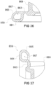
- the peripheral seal may comprise a downwardly directed peripheral skirt depending generally downwardly from the periphery of the sealing closure.
- the peripheral skirt preferably comprises a radially inwardly curved portion, when the sealing closure is viewed in transverse cross section, the radially inwardly curved portion defining a channel configured to receive a margin of the humidification chamber, and/or part of a respiratory apparatus in which the humidification chamber is used, when the sealing closure is mounted on the humidification chamber.
- the peripheral seal may further comprise a bead projecting upwardly and/or radially outwardly from an upper surface of the sealing closure. The bead may be configured to support a lid of the respiratory apparatus with which the humidification chamber is used.
- the sealing closure may comprise a hand or finger grip formation configured to be gripped to remove the sealing closure from the humidification chamber.
- the hand or finger grip formation may comprise a tab projecting from the sealing closure.
- the water tub may be formed of rigid plastic and comprises a base surface and a perimeter wall that extends upwardly from the base, and wherein the base surface comprises a heater plate.
- the heater plate may be secured within an aperture of the base surface of the water tub by overmoulding.
- the heater plate may be metallic.
- the humidification chamber may further comprise a step formation about an inner surface perimeter of a wall of the water tub, the step formation being configured at a height above a base surface of the water tub corresponding to a maximum fill line indicator.
- the base surface of the water tub is domed such that it curves outward toward a central apex defined by the heater plate.
- the perimeter wall of the water tub comprises one or more reinforced regions.
- the humidification chamber may further comprise a lid hingedly coupled to the water tub for enclosing the water tub to define the interior volume of the humidification chamber and which is movable between a closed position in which the water tub is closed by the lid and an open position in which the water tub is open.
- One or more operable clips may be provided for securing the lid in the closed position; the sealing closure being configured to be releasably mounted on the lid.
- the lid and water tub may be hingedly coupled by a living hinge and are integrally formed as a single item.
- the gases inlet and gases outlet may be provided on opposite sides of the lid.
- the lid may comprise a vertical flow plane that extends downwardly from the underside of the lid in a central region of the lid.
- the vertical flow plane may further comprise a pair of side baffles that each extend from a respective side edge of the vertical flow plane toward the side of the lid comprising the gases inlet.
- the gases inlet may be coupled to an inlet conduit that extends between an inlet end at the gases inlet and an outlet end located at or toward an upper central region of the interior volume of the humidification chamber and adjacent a first side surface of the vertical flow plane such that the incoming gases flow enters the interior volume of the humidification chamber at that upper central region.
- a flow director formation in the form of an inverted curved ramp surface may be located between the outlet end of the inlet conduit and the first side surface of the vertical flow plane.
- the gases outlet may be coupled to an outlet conduit that extends between an inlet end located at or toward an upper central region of the interior volume of the humidification chamber and adjacent a second side of the vertical flow plane and an outlet end at the gases outlet.
- the gases outlet may comprise an engagement surface about the perimeter of the gases outlet that is tilted outwardly such that an upper portion of the engagement surface is displaced further outward than a lower portion of the engagement surface.
- At least one water fill aperture may comprise an associated maximum water level indicator comprising a tab member that is supported from the underside of the top of the water tub or lid such that it extends into the field of view of the interior volume of the humidification chamber visible directly through the water fill aperture.
- the humidification chamber has an overall shape defined by front and end walls between which side walls extend, and the walls extending between an upper surface of a lid and base surface of the water tub, and wherein the lid is hingedly coupled to the water tub at the rear end of the humidification chamber, and at least one operable clip is provided at the front end of the humidification chamber.
- At least one operable clip may be provided in the form of a torsion clip that is mounted to either the lid or water tub and which is configured to engage with a catch provided on either the water tub or lid, respectively.
- At least one operable clip may be provided that is hingedly coupled to the lid or water tub and which is configured to engage with a catch provided on either the water tub or lid, respectively.
- a seal may be provided about the perimeter of the chamber between the lid and water tub to seal the chamber when it is in a closed position.
- a respiratory assistance device configured to provide a heated and humidified gases stream, comprising:
- the humidification compartment may comprise a lid that is movable between an open position to enable removal of the humidification chamber and a closed position to retain the humidification chamber within the humidification compartment.
- the gases inlet of the humidification chamber may be open within the humidification compartment to receive an incoming flow of gases from within the pressurised humidification compartment.
- the gases outlet of the humidification compartment may be sealingly connected to the gases outlet of the humidification chamber.
- the humidification compartment may comprise a heater pad upon which the humidification chamber sits.
- the device may be contained within a single housing.
- the device may be a CPAP respiratory device.
- a sealing closure for a humidification chamber for humidifying gases comprising:
- a sealing closure for sealingly closing at least one fill aperture of a humidification chamber for humidifying gases, the sealing closure:
- a humidification chamber according to the invention as claimed is formed, in the following detailed description, by the tub of any of the embodiments of Fig. 3-22N and 24A-26 , with a sealing closure as in Fig. 27-37 .
- the disclosure relates to a humidification chamber for a respiratory assistance apparatus (respiratory device) that supplies a flow or stream of heated and humidified respiratory gases to a user or patient for respiratory therapies, such as, but not limited to, CPAP therapy.
- a respiratory assistance apparatus respiratory device
- respiratory therapies such as, but not limited to, CPAP therapy.
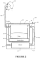
- FIG. 2 shows an example of a typical schematic configuration of a respiratory device 20 within which the humidification chamber of the disclosure may be employed, although this is not intended to be limiting to the uses of the humidification chamber.
- the respiratory device 20 comprises a humidification unit or humidification compartment 22 that receives and retains a removable humidification chamber 24 in use.
- the humidification compartment 22 may be formed within the housing of the respiratory device and may be an openable compartment having a lid so the humidification chamber 24 within the humidification compartment 22 may be accessed for removal for cleaning or filling.
- the humidification compartment 22 is sealed and/or pressurised when the lid is closed.
- the humidification chamber 24 is filled with a volume of water as indicated at 26 and the chamber 24 rests upon a heater pad or heater base 28.
- the heater pad 28 is powered to heat the water 26 in the humidification chamber 24 during use via heat transfer through the base of the humidification chamber 24 of which at least a portion is thermally conductive.
- the respiratory device 20 comprises a blower 30 which draws atmospheric air or other therapeutic gases through an inlet 32 and generates a pressurised gases stream 34 at an outlet of the blower.
- the outlet of the blower 30 is fluidly connected to an inlet 36 of the humidification compartment 22 via connecting conduits 38 extending to the inlet 36 of humidification compartment 22.
- the gases stream 34 entering the inlet 36 pressurises the compartment and gases flow into the open gases inlet 37 of the humidification chamber 24.
- the inlets 36, 37 of the compartment 22 and chamber 24 may be sealingly connected by a connector or other sealing configuration.
- the pressurized gases stream passes through the humidification chamber 24 and exits via gases outlet 40 of the humidification chamber.
- the gases outlet 40 of the chamber 24 is sealingly connected to or sealingly engaged with an outlet 41 of the humidification compartment 22 as shown. It will be appreciated that in alternative embodiments, the outlets 40, 41 of the compartment 22 and chamber 24 need not be sealingly connected by a connector or otherwise sealingly engaged.
- the outlet 41 of the humidification compartment 22 is fluidly connected via connectors and/or conduits to a patient interface for delivery to a patient 42.
- the patient interface typically comprises a flexible gases conduit 44 coupled at one end to the main gases outlet of the respiratory device 20 and to a user interface 46 at the other end.
- the humidification chamber 24 is typically received and retained within a complimentary enclosed and sealable humidification compartment 22 formed in the housing of the respiratory device 20.
- the humidification chamber 24 could alternatively be received and retained in an open or exposed compartment or on a support platform comprising the heater pad 28 in alternative embodiments with the gases inlet of the chamber being connected to the blower outlet by conduits and/or connectors and the gases outlet of the chamber being connected by conduits and/or connectors directly or indirectly to the patient interface.
- Humidification chamber - discontinuous cradle with lid Humidification chamber - discontinuous cradle with lid.
- the humidification chamber or chamber assembly 50 comprises a cradle or lower part generally indicated at 52 that is shaped to receive and retain a complimentary sized and dimensioned water tub or container 54.
- An upper part or lid 56 is hingedly coupled to the cradle 52 and is moveable between a closed position (shown in Figure 3 ) in which the lid securely retains the water tub 54 within the cradle 52 and an open position in which the lid is pivoted away from the cradle 52 to enable the water tub 54 to be removed from the cradle for cleaning, refilling or replacement for example.
- the lid may comprise baffling in the form of a configuration of conduits and/or flow planes and guides to control the flow path of the gases stream through the chamber between the inlet and outlet.
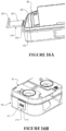
- a gases outlet 150 is provided on the opposite side of the humidification chamber to the gases inlet 140.
- the gases outlet 150 is provided on the outlet side perimeter wall 108 of the lid 56 of the humidification chamber and like the gases inlet 140 is centrally located relative to the front and rear ends of the humidification chamber, although this is not essential.
- the gases outlet 150 comprises an aperture extending through the perimeter wall 108 that is substantially rectangular, although other shaped apertures such as circular or otherwise could alternatively be utilized.
- the gases outlet 150 comprises an outlet conduit 152 that extends into a central zone or region of the lid of the humidification chamber from gases outlet aperture in a horizontal or perpendicular direction relative to the perimeter wall 108.
- the outlet conduit 152 extends from a first end 152a located at the aperture of the gas outlet 150 in the wall 108 and extends into the interior of the lid 56 and terminates at second end 152b.
- the second end 152b of the outlet conduit 152 abuts or engages with the second side 146c of the vertical flow panel 146.
- the outlet conduit 152 is substantially rectangular having lower 152c and upper 152d walls and left 152e and right 152f side walls which extend along its length.
- two main inlet apertures 154a and 154b are provided at or towards the second end 152b of the inlet conduit in each of the side walls 152e and 152f such that inlets open toward either the front or rear ends of the lid.
- the inlet apertures 154a, 154b are substantially rectangular, but may be circular or otherwise.
- vertical wall formations 155a, 155b extend up from the lower wall 152c of the conduit in the region of each respective inlet aperture 154a, 154b.
- the wall formations 155a, 155b act as water splash barriers and are configured to force the gases stream to move up around the wall before entering the apertures 154a, 154b rather than moving directly into the apertures from the surface of the water directly underneath the apertures. This configuration reduces the likelihood of water being picked up or carried by the gases stream (particularly at high flow rates) and entering into the outlet conduit 152.
- the inlet conduit 152 need not necessarily extend all the way into contact with the vertical flow panel 146, and may alternatively terminate at a position between the vertical flow panel 146 and side wall 108 of the lid.
- the gases inlet 140 and the gases outlet 150 have associated conduits 142 and 152 for creating the desired gas flow path within the humidification chamber to maximize humidification, although it will be appreciated that these conduits are not essential.
- the gases inlet 140 and gases outlet 150 may simply be apertures in the side walls without conduits extending into the interior of the humidification chamber.
- inlet and outlet conduits 142, 152 When inlet and outlet conduits 142, 152 are provided, it will be appreciated that these need not necessarily enter the chamber lid centrally from opposite sides at a perpendicular angle to the respective perimeter walls.
- the conduits may be located at corners of the lid and may enter the chamber at any desired angle. Additionally, the conduits need not necessarily be straight conduits, but could be non-straight, and include one or more bends or turns.
- gases inlet 140 and gases outlet 150 of the humidification chamber may be connected into the gas flow path of the respiratory device in various ways.
- the gases inlet 140 may be coupled or fluidly connected into the gases flow path by one or more conduits, connectors, and/or gaskets that are coupled to the gases flow path exiting the blower, in a sealed or non-sealed configuration.
- gases outlet 150 may be coupled in any suitable manner, including connectors, conduits and/or gaskets in a sealed or non-sealed configuration to the gas flow path leading to the gases outlet of the respiratory device, which is in turn connected to a patient interface, such as a flexible gases delivery conduit and user interface, as previously discussed.
- the chamber is retained within a sealable humidification compartment comprising a gases inlet that is fluidly connected to the blower outlet and a gases outlet that is fluidly connected to the main gases outlet of the respiratory device, which is typically coupled or connectable to a patient interface.
- the gases inlet 140 of the chamber is not sealingly connected to the inlet of the compartment but rather open to the pressurized gases entering the sealed compartment.
- a sealed connection between the inlet of the chamber and compartment may be employed.
- the gases outlet 150 of the chamber is preferably sealingly connected or coupled via a gasket or other sealed connection configuration to the gases outlet of the humidification compartment or at least closely aligned to each other to minimize gas bypassing the chamber directly to the compartment outlet.
- the lid 56 is hingedly coupled or connected to the cradle 52 such they are moveable between an open position in which lid is pivoted away from the cradle to enable the water tub 54 to be removed from the cradle (or to allow the tub to be filled with water or cleaned with the lid open) and a closed position in which the lid pivots into engagement with the cradle to encapsulate and secure the water tub between the lid and cradle.
- the lid 56 is pivotal about a hinge located at the rear end of the chamber between the closed position or configuration as shown in Figure 3 and the open position or configuration as shown.
- one or more hinges are located at the rear end of the humidification chamber which are configured to hingedly couple the lid 56 to the cradle 52.
- a single elongate living hinge 160 extends along a portion of the rear end of the humidification chamber between the lid 56 and cradle 54.
- the living hinge 160 is a thin flexible plastic hinge that is integrally formed and coupled between a portion of the upper edge 76e of the rear wall 76 of the cradle and a portion of the ledge 105 at the rear end of the lid 56.
- two or more hinges may be provided along the rear end of the humidification chamber between the lid and cradle and the hinges need not necessarily be integrally formed living hinges but may be hinges or hinging mechanisms that are formed separately and attached or fixed to the lid and cradle.
- one or more operable clips or clipping mechanisms are provided and are operable between a latched or locked position for securing the humidification chamber in a closed position, or an unlatched or unlocked position to enable lid 56 to be pivoted away from the cradle into the open position or configuration.
- a single operable clip 170 is provided or fixed to the lid 56 and which is resiliently moveable between an engaged position and disengaged position with a complimentary catch 172 provided on the cradle 52.
- the clip 170 is provided in a central location on the front wall 102 of the lid 56.
- the operable clip 170 is in the form of a torsion clip that is moveable between an engaged and disengaged position relative to the complimentary catch 172 provided on the cradle 52.
- the clip 170 comprises a user contact portion 174 that may be pressed by a user to move or pivot the clip into a disengaged position and an engagement tab portion 176 which comprises an engagement aperture 176a.
- the catch 172 is a protrusion or engagement formation that protrudes from the front wall 74 of the cradle and is aligned with the clip such that it engages into engagement aperture 176a of clip 170 when the clip is in a latched or locked position to thereby secure the lid 56 to the cradle 52.
- an angled front camming surface 314 extends downwardly and outwardly from the front wall and a substantially horizontal engagement surface 316 returns back to the front wall from the lower edge of the front camming surface 314.
- the U-shape clip 310 comprises two vertical legs 318 which extend downwardly from the lid and are joined by a cross-member 320. In use the cross-member 320 engages with the camming surface 314 of the catch formation 312 as the lid is brought into engagement with the cradle 352 until snapping or locking into full engagement with engagement surface 316.
- the second embodiment humidification chamber 300 is substantially similar to the first embodiment, and comprises a plastic lid 56 that is hingedly coupled with a plastic cradle 352 which receives a metal water tub of the type previously described.
- the primary difference of the second embodiment humidification chamber 300 is that the cradle is substantially continuous about the peripheral wall of the water tub such that it substantially encapsulates and surrounds the entire water tub peripheral wall surface.
- a third embodiment humidification chamber 400 will be described in further detail.
- the humidification chamber 400 is similar in overall shape to the previous embodiments, and where applicable similar features are represented by similar drawing reference numerals. It will be appreciated that the description of the previous embodiments in relation to similar features, including variants or alternatives, also applies to this embodiment and will not be repeated. The following description focuses on the differences of the third embodiment relative to the previous embodiments.
- the primary difference with the third embodiment humidification chamber 400 is that it is a two-part chamber assembly, rather than a three-part chamber assembly like the previous embodiments.
- the phrases "two-part” and “three-part” assemblies are intended to refer to the number of main components of the assembly, regardless of whether they are integrally formed or otherwise connected, coupled or assemble together.
- the previous embodiments relate to three-part chamber assemblies comprising: an upper part (lid - part one) which is hingedly coupled to open and close relative to a lower part (cradle - part two) which releasably receives and retains a separate water tub (part three).
- this third embodiment humidification chamber 400 is a two-part assembly comprising the upper part in the form of a lid 456 (part one) that is hingedly coupled at one side to a lower part that is the form of a water tub 452 (part two) comprising a thermally conductive metallic heater plate in its base surface.
- the lid 456 and water tub 452 are formed of a rigid plastic by injection moulding, vacuum forming, or some other suitable production process, in a similar manner to the formation of the lid and cradle of the previous embodiments.
- the lid 456, water tub 452, and hinged coupling 160 between the lid and water tub are integrally formed together as a single item, although in alternative embodiments the lid and water tub may be formed as separate parts and then hingedly coupled via one or more separate hinging components or assemblies.
- the water tub and/or lid may be substantially transparent or formed as opaque depending on design requirements.
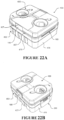
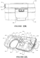
- the humidification chamber 400 is operable or moveable between a closed position in which the lid 456 is secured to the water tub 452 to create an enclosed chamber (as shown in Figures 22A and 22B for example) and an open position or configuration as shown in Figures 22L-22N in which the lid 456 is displaced or rotated about the hinge 160 away from the water tub to open the chamber for access.
- One or more operable clips 290 or latches are provided at the front end of the humidification chamber for securing or locking the humidification chamber into the closed position ready for insertion and operation within a respiratory device as previously discussed.
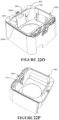
- the water tub 452 comprises a base surface 470 from which upright sidewalls extend about the periphery of the base surface. As shown, the water tub comprises front 474 and rear 476 walls at the front and rear ends of the humidification chamber respectively, and first 475 and second 477 sidewalls extending along the gases inlet and gases outlet sides of the humidification chamber respectively.
- one or more of the walls or portions of the walls may be provided with a reinforcing profile that is configured to resist bending or deformation of the wall surfaces.
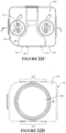
- each of the sidewalls 475, 477 are provided with reinforced portions or regions 478, 479 respectively comprising a corrugated or undulating surface profile of alternate furrows and ridges.
- the furrows and ridges have a vertical orientation, but it will be appreciated that a horizontal orientation may be used in the alternative if desired.
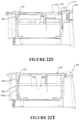
- the thickness of the sidewalls in the reinforced or corrugated regions is substantially uniform such that the ridges and furrows and the transition zones between the ridges and furrows are of a substantially similar wall thickness as can be seen in Figure 22D .
- the thickness of the sidewalls in the reinforced regions may be non-uniform.
- the height of each corrugated region extends on the sidewalls from the base surface to an intermediate point below the edge or rim of the water tub as shown in Figures 22E and 22F , but it will be appreciated that the corrugated region may start at a point above the base surface or alternatively the corrugated region may extend the entire height of the sidewalls if desired.
- spaced-apart reinforcing ridges or ribs may be provided on one or more portions of the side walls, on either the inner or outer surfaces, or both.
- the ridges or ribs increase the thickness of the wall in the region of the ridge or rib.
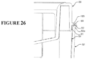
- the sidewalls of the water tub 452 may be stiffened or reinforced to prevent or minimise bending and/or deformation with a perimeter ledge, lip, or rim extending or protruding outwardly from or at the top perimeter edge of the water tub sidewalls.
- the rim may be of the type or form shown at 92 or 52a in Figure 26 for example, i.e. integrally formed about the upper perimeter edge of the sidewalls.
- the reinforcing rim may be provided in combination with the reinforced regions of the sidewalls or as an alternative instead of the reinforcing regions.
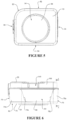
- the humidification chamber 400 comprises a convex or domed base surface 470 that is curved or rounded outward toward an apex defined by a central heater plate, discussed further next.
- the base surface 470 may be substantially flat.
- the base surface 470 of the water tub 452 is provided with a centrally located metallic or thermally conductive heater plate 494.
- the heater plate 494 is circular and joined or fixed into a complementary circular aperture provided in the centre of the base surface 470 of the plastic water tub 452 by overmoulding.
- the heater plate may be formed of a rigid and thermally conductive material, and is typically pressed or shaped from sheet metal, such as aluminium, stainless steel or any other suitable material, or could be formed by die casting for example.
- the heater plate 494 and complementary aperture in the base surface 470 of the water tub are circular, although it will be appreciated that this shape may be varied to provide an integrated heater plate surface of any other alternative shape, including square, rectangular, or any arbitrary shape.
- the heater plate 494 is substantially flat prior to the overmoulding process but may have a slightly outwardly domed or convex profile caused by compression force from the surrounding domed base surface after the overmoulding process.
- the compression force or bias which causes the slightly outwardly convex engagement surface of the heater plate reduces or resists the likelihood of the heater plate being deformed inwardly overtime and usage as a deformed inwardly concaved engagement surface would reduce the contact surface area of the heater plate with the heater pad it sits on in the humidification compartment, which would reduce the heat transfer efficiency of the configuration.
- the heater plate 494 is provided with a main circular contact surface 495 that is configured to protrude or extend beyond the surrounding plastic base surface 470 of the water tub 452, to encourage full engagement and heat transfer when the chamber sits on a complementary shaped heater pad in the bottom of the humidification compartment.
- the heater plate further comprises an upright or substantially vertical wall portion 496 that extends around the periphery of the main contact surface portion 495 and an outer substantially horizontal peripheral coupling surface or ledge portion 497 that extends outwardly from the top of the wall portion 496 around the perimeter of the heater plate.
- the main contact surface portion 495 and outer coupling ledge 497 extend in substantially parallel planes but are displaced vertically from each other by the height of the vertical wall portion 496.
- the coupling ledge 497 of the heater plate 494 that is coupled or fixed to the surrounding plastic about the periphery of the central aperture of the base surface 470 by overmoulding.
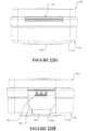
- an engagement portion 471 of the base surface material about the periphery of the central aperture of the base surface 470 is moulded over at least a portion of the coupling ledge 497 of the heater plate 494, about its entire periphery.
- the overmoulding process is configured to vary the thickness of the engagement portion 471 of the base surface relative to the remainder of the base surface.
- the overall thickness 401 of the engagement portion 471 that is moulded over at least a portion of the coupling ledge 497 of the heater plate 494 is larger than the thickness 402 of the remaining base surface 470 of the water tub. This configuration assists in reducing lifting of the plastic of the base surface 470 away from the coupling ledge 497 of the heater plate after moulding, which in turn reduces the amount of hard water deposit ingress at the transitional interface region between the metal heater plate and plastic base surface.
- the thickness 403 of an upper portion of the engagement portion 471 above the coupling ledge 497 of the heater plate 494 is similar to or at least as thick as the thickness 402 of the remaining base surface, to reduce or minimise lifting of the upper portion away from the coupling ledge 497.
- the thickness 404 of a lower portion of the engagement portion 471 below the coupling ledge 497 may be of smaller thickness than the thickness 403 of the upper portion of the engagement portion 471 of the base surface 470.
- the thickness 404 of the lower portion of the engagement surface may also be similar to or at least as thick as the thickness 402 of the remaining base surface to reduce or minimise lifting of lower portion from the coupling ledge.
- the heater plate may be a substantially flat circular plate which is secured within the central aperture of the base surface by overmoulding such that it is substantially flush with the remainder of the base surface rather than protruding as described above.
- the water tub 452 is also provided with a continuous horizontal step formation 472 extending about the perimeter of the inner sidewall surface.
- the step formation is displaced a uniform height from the base surface of the water tub about the inner perimeter.
- the step formation is integrally formed into the sidewalls and may be in the form of an angled step as shown in Figure 22I .
- the step formation 472 is located at a height from the base surface that corresponds to a maximum fill line.
- the lid 456 of the third embodiment humidification chamber 400 is substantially similar to the lid 56 of the previous embodiments, although there are some main differences, which will be explained in the following. It will also be appreciated that the third embodiment humidification chamber could also use the same lid 56 as previously described.
- the lid 456 is provided with tab water level indicators 220 of the type explained previously with reference to Figures 18A and 24B .
- the tab water level indicators 220 comprise an angle tab 134 which is suspended below each water fill aperture 120 by upright support members 132, 221 at each end.
- the indicia "MAX" for maximum is printed backwards on the underside surface of the tab portions 134 as shown in Figure 22L .
- At least the tab portions 134 are formed of transparent plastic such that the indicia "MAX" is presented to the user through in the correct readable format when viewed through the water fill holes 120.
- the inlet side perimeter wall 106 of the lid 456 is provided with a projection or projections 407, such as bumps or ridges or formations, that extend from the surface of the perimeter wall.
- a protrusion 407 is provided on each side of the central inlet aperture 140 of the lid for engaging with aligned rails provided on the inner inlet gases side wall of the humidification compartment, which will now be explained.
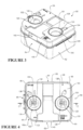
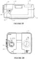
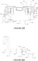
- FIG 22O shows a lower part of a humidification compartment 800 that is shaped and dimensioned with a complementary cavity 802 that receives and retains the humidification chamber 400.
- the lower part of the humidification compartment may be part of the housing or body of a respiratory device of the type previously described.
- the humidification compartment may further comprise an openable lid for sealing or enclosing the compartment once the humidification chamber 400 is installed in the cavity.
- two vertical rails 406 protrude from the inner wall surface of the humidification compartment on each side of the gases inlet 804, which receives a flow of gases from the blower of the respiratory device as explained previously with reference to Figure 2 .
- each rail 806 extends from a first upper end at or toward the height of the gases inlet 804 and a second lower end at or toward the floor surface of the compartment.
- each rail comprises a first short start ramp portion 806a that tapers or slopes outwardly from the wall surface, and then extends into a second longer return ramp portion 806b that tapers or slopes back toward the inner wall surface.
- the protrusions 407 on the gases inlet side of the humidification chamber 400 are aligned with engagement rails 806 on the inlet side of the humidification compartment.
- the protrusions 407 abut or engage with their respective rail 806, and the rails urge the chamber 400 toward the opposite outlet sidewall of the compartment comprising the gases outlet 808, which is shown in Figure 22P .
- the height (H) of the flow panel 146 is typically configured such that it protrudes or penetrates sufficiently deeply into the surface of the water to prevent gases exiting the inlet conduit 142 from shortcutting underneath the lower edge 146a and directly to the outlet conduit 152.
- the upper part or lid 456 is hingedly coupled or connected to the lower part or water tub 452 such that they are moveable between an open position in which the lid is pivoted away from the water tub (to allow the tub to be filled with water or cleaned with the lid open) and a closed position in which the lid pivots into engagement with the water tub to close the chamber.
- lid 456 is hingedly coupled to the water tub 452 in a similar manner to the hinging coupling between the lid and cradle of the previous embodiments.
- the lid 456 is pivotable about a hinge located at the rear of the chamber between the closed position or configuration shown in Figures 22A and 22B and an open position or configuration as shown in Figures 22L-22N , for example.
- the hinge is a single elongate living hinge 160 that extends along a portion of the rear end of the humidification chamber between the lid 456 and water tub 452, and is of a form as previously described in the previous embodiments.
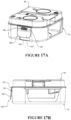
- the humidification chamber comprises a single operable clip 290 and complementary catch formation 192 of the type described with reference to Figures 217A and 17B .
- the clip 290 is pivotably mounted to the lid and is moveable into engagement with the catch 192 to securely close the chamber or may be disengaged or released from the catch 192 to enable the chamber to be opened.
- a recessed portion 195 is provided on the front wall of the water tub 452 in the vicinity of the clip 290 to enable a user to grip and pull the tab to disengage the clip from the catch formation 192 when desired.
- the third embodiment chamber 400 need not necessarily be sealed between the lid 456 and water tub 452. However, it may be sealed if desired as shown in this embodiment.
- the ledge 105 of the lid 456 is provided with or forms a perimeter groove or recess and a seal 99 is mounted in the groove about the perimeter of the lid in a similar configuration to that described with reference to the embodiment of Figure 26 . As shown, the seal 99 engages with the upper surface or rim 461 of the perimeter wall of the water tub 452 when the chamber is closed to seal the chamber.
- the other seal configurations discussed with reference to Figure 26 may also be employed in alternative configurations.
- the fourth embodiment humidification chamber 500 is a variant of the second embodiment humidification chamber 300.
- the lid 56 is not hingedly coupled at one end to a full cradle but rather to a sleeve 552 in the form of a continuous perimeter wall that encircles or extends about the entire peripheral wall of the water tub 54 as shown.
- the sleeve 552 leaves the entire base surface 54 in the water tub exposed.
- the sleeve 552 is preferably formed of the same material as the lid, for example injection moulded from plastic or similar.
- the height of the sleeve as indicated at 554 may be varied as desired.
- the fifth embodiment humidification chamber 600 (see Figure 24C ) comprises a plastic lid 602 which is releasably coupled to a metal water tub 604 (see Figure 30B) via internal clips.
- the plastic lid 602 is substantially similar to the lids of the previous embodiments although comprising a slightly different water level indicator configuration.
- a finger gripping recess 610 is provided centrally on the water level indicator end of the lid.
- the internal structure of the lid 602 is otherwise similar, including the gases inlet, gases outlet and vertical flow plane configuration.
- the water tub 604 is entirely formed from metal such as stainless steel, aluminium or similar.
- a sleeve or cradle of insulating material such as plastic or other thermally insulating material may be provided on the outer peripheral walls and/or underside surfaces of the metal tub to prevent user from burning their hands if picking up the metal tub, although the user may pick up the metal tub via the lid by gripping of the water fill aperture 606 and the figure grip recess 610 with a finger and thumb for example.
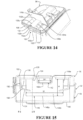
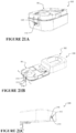
- FIG. 25A shows the sixth embodiment humidification chamber 700 which will be described.
- This embodiment comprises a plastic lid 702 which clips into a complimentary shaped metal water tub 704 by a similar manner described above with reference to the fifth embodiment humidification chamber 600.
- Figure 25A shows the inlet aperture 706 of the humidification chamber and
- Figure 25B shows the gases outlet 708 of the humidification chamber.
- a sealing closure 850 is configured for mounting upon a humidification chamber 24, 50, 300, 400, 500, 600 or 700 and optionally a humidification compartment 22 of a respiratory device 20 in which a humidification chamber is positioned as described in previous embodiments with reference to Figures 1 to 26 .
- the sealing closure 850 directly on the humidification chamber may provide one or more advantages over prior art arrangements.
- the sealing closure is not permanently attached to any component and can be relatively easily removed for cleaning or replacement.
- the sealing closure 850 as will be described in more detail below, is relatively simply, quickly and easily mounted on the humidification chamber simply by pushing the sealing closure 850 onto the chamber.
- the sealing closure 850 is mounted on the chamber simply by pushing parts of the sealing closure into the fill apertures of the chamber.
- the sealing closure 850 may provide some thermally insulating function which reduces heat loss from the humidification chamber, by virtue of the material of the sealing closure 850, and/or any air pocket(s) that are present between the underside of the sealing closure 850 and the humidification chamber.
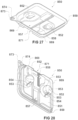
- the sealing closure 850 in this example is configured such that the shape, cross sectional profile, dimensions and features of an undersurface 851 of the sealing closure 850 are complimentary to the shape, cross sectional profile, dimensions and features of the uppermost surfaces of the humidification chamber upon which the sealing closure 850 is mounted.
- the sealing closure 850 in this example, is oblong with rounded corners when viewed in plan. One corner has a significantly larger radius than the other three corners, and the gripping tab 873 extends from that larger radius corner.
- the sealing closure 850 may be any other shape as required to correspond to the shape of the humidification chamber 50 and/or the shape of the humidification compartment 22.
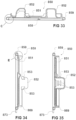
- the sealing closure 850 is of unitary construction of planar sheet material, being a single component with the features described above formed in the sheet.
- the sealing closure 850 is resiliently deformable and flexible and may be manufactured from any suitable material, such as a rubber and/or silicone material for example.
- the material, and dimensions of the sealing features may be selected such the sealing closure 850 engages the humidification chamber and deforms sufficiently to form a sealing engagement with the humidification chamber and/or the humidification compartment 22, where required.
- the plugs 852 may resilient deform as they are pushed into the fill apertures 120 to sealingly engage therewith.
- a sealing closure in accordance with one or more aspects of the above disclosure may provide one or more advantages over prior art arrangements.
- the sealing closure may assist in reducing or preventing spillage from the humidification chamber during filling and/or carrying of the humidification chamber.
- use of a hinged sealing closure may help to reduce condensation dripping from the closure into the chamber at the end of therapy.
Landscapes
- Health & Medical Sciences (AREA)
- Life Sciences & Earth Sciences (AREA)
- General Health & Medical Sciences (AREA)
- Engineering & Computer Science (AREA)
- Anesthesiology (AREA)
- Biomedical Technology (AREA)
- Heart & Thoracic Surgery (AREA)
- Hematology (AREA)
- Emergency Medicine (AREA)
- Pulmonology (AREA)
- Public Health (AREA)
- Animal Behavior & Ethology (AREA)
- Veterinary Medicine (AREA)
- Air Humidification (AREA)
- Devices For Medical Bathing And Washing (AREA)
- Ventilation (AREA)
- Investigating Or Analysing Biological Materials (AREA)
- Accommodation For Nursing Or Treatment Tables (AREA)
Applications Claiming Priority (2)
| Application Number | Priority Date | Filing Date | Title |
|---|---|---|---|
| US201662330662P | 2016-05-02 | 2016-05-02 | |
| PCT/NZ2017/050047 WO2017192051A1 (en) | 2016-05-02 | 2017-04-27 | Humidification chamber and chamber seal for a respiratory assistance apparatus |
Publications (3)
| Publication Number | Publication Date |
|---|---|
| EP3452159A1 EP3452159A1 (en) | 2019-03-13 |
| EP3452159A4 EP3452159A4 (en) | 2020-01-01 |
| EP3452159B1 true EP3452159B1 (en) | 2025-04-09 |
Family
ID=60203067
Family Applications (1)
| Application Number | Title | Priority Date | Filing Date |
|---|---|---|---|
| EP17792936.1A Active EP3452159B1 (en) | 2016-05-02 | 2017-04-27 | Humidification chamber for humidifying gases |
Country Status (8)
| Country | Link |
|---|---|
| US (3) | US11135393B2 (enExample) |
| EP (1) | EP3452159B1 (enExample) |
| JP (3) | JP7291482B2 (enExample) |
| CN (3) | CN109152907B (enExample) |
| AU (3) | AU2017261121B2 (enExample) |
| CA (1) | CA3020293A1 (enExample) |
| SG (2) | SG10202010888YA (enExample) |
| WO (1) | WO2017192051A1 (enExample) |
Families Citing this family (12)
| Publication number | Priority date | Publication date | Assignee | Title |
|---|---|---|---|---|
| CA2883336A1 (en) | 2012-09-07 | 2014-03-13 | Fisher & Paykel Healthcare Limited | Humidification chamber for a respiratory assistance apparatus |
| SG10202010888YA (en) | 2016-05-02 | 2020-12-30 | Fisher & Paykel Healthcare Ltd | Humidification chamber and chamber seal for a respiratory assistance apparatus |
| US11376392B2 (en) * | 2018-04-24 | 2022-07-05 | ResMed Pty Ltd | Tub for use in a humidifier |
| EP3586897A1 (en) * | 2018-06-29 | 2020-01-01 | Koninklijke Philips N.V. | Humidifier for a system for providing a flow of breathable gas |
| CN112546379B (zh) | 2018-10-26 | 2025-08-05 | 北京瑞迈特医疗科技股份有限公司 | 呼吸通气设备 |
| WO2020096468A1 (en) * | 2018-11-09 | 2020-05-14 | Fisher & Paykel Healthcare Limited | Humidification apparatus |
| CN110368568B (zh) * | 2019-08-16 | 2020-11-06 | 山东大学 | 一种大蒜素呼吸治疗仪 |
| TWI785276B (zh) * | 2019-09-27 | 2022-12-01 | 雃博股份有限公司 | 呼吸系統 |
| EP4081285B1 (en) * | 2019-12-24 | 2025-10-08 | ResMed Pty Ltd | Apparatus for humidifying a respiratory gas |
| CN115996774A (zh) * | 2020-09-08 | 2023-04-21 | 瑞思迈私人有限公司 | 与便携式cpap装置一起使用的湿化平台 |
| US20230075277A1 (en) * | 2021-08-26 | 2023-03-09 | ResMed Pty Ltd | Air preheater for humidification tub |
| CN118949206B (zh) * | 2024-09-18 | 2025-01-24 | 上海莹普露科技有限公司 | 一种具有智能流量控制功能的氧气输送系统及氧气供应设备 |
Family Cites Families (78)
| Publication number | Priority date | Publication date | Assignee | Title |
|---|---|---|---|---|
| US3005591A (en) * | 1961-06-28 | 1961-10-24 | Oster Mfg Co John | Atomizing type portable humidifier |
| US4028444A (en) * | 1974-03-25 | 1977-06-07 | Chemetron Corporation | Humidifier and automatic control system therefor |
| US4203027A (en) | 1977-03-07 | 1980-05-13 | Fisher & Paykel Limited | Electrically heated humidifying apparatus |
| US4152379A (en) | 1977-05-26 | 1979-05-01 | Airco, Inc. | Anesthesia humidifier |
| US4261353A (en) * | 1979-08-20 | 1981-04-14 | Bourns Medical Systems, Inc. | Humidifier filler |
| US4303601A (en) | 1980-03-31 | 1981-12-01 | Baxter Travenol Laboratories, Inc. | Ventilator humidifier |
| JPS6174549A (ja) | 1984-09-20 | 1986-04-16 | Oozeki Syuzo Kk | 飼料の製造法 |
| JPH0417490Y2 (enExample) | 1984-10-19 | 1992-04-20 | ||
| US4676237A (en) | 1985-01-29 | 1987-06-30 | Boutade Worldwide Investments Nv | Inhaler device |
| US5527513A (en) * | 1994-04-08 | 1996-06-18 | Becton Dickinson And Company | Collection assembly |
| JP3630772B2 (ja) * | 1994-07-15 | 2005-03-23 | 株式会社日本触媒 | 放射性薬液封入容器用輸送容器 |
| US5564415A (en) | 1995-06-07 | 1996-10-15 | Lifecare International, Inc. | Humidifier for a ventilator |
| DK0773172T3 (da) | 1995-11-07 | 2000-11-06 | Nestle Sa | Hængslet lukke for en beholder |
| DE19630466C2 (de) | 1996-07-27 | 1998-05-07 | Nikolaus Netzer | Vorrichtung zur Gaszufuhr bei Schlafapnoe |
| JP3060967B2 (ja) | 1996-10-16 | 2000-07-10 | タイガー魔法瓶株式会社 | 加湿器 |
| US5943473A (en) | 1997-05-29 | 1999-08-24 | Levine; Walter | Heated cartridge humidifier |
| JPH11347126A (ja) | 1998-06-05 | 1999-12-21 | Sumitomo Bakelite Co Ltd | 医療用酸素濃縮気体供給装置 |
| US6398197B1 (en) | 1999-05-10 | 2002-06-04 | Fisher & Paykel Limited | Water chamber |
| DE29909611U1 (de) | 1999-06-02 | 1999-09-02 | Hoffrichter, Helmut, Dipl.-Ing., 19057 Schwerin | Anordnung für einen beheizbaren Atemluftbefeuchter |
| AUPQ339099A0 (en) | 1999-10-13 | 1999-11-04 | Resmed Limited | A humidifier |
| DE10049869A1 (de) | 2000-10-10 | 2002-04-11 | Weinmann G Geraete Med | Vorrichtung zur Beatmung sowie Verfahren zur Steuerung |
| EP1359963B1 (en) | 2001-02-16 | 2013-07-17 | ResMed Limited | Air pressure signal monitoring in apparatus for treating sleep disordered breathing |
| JP2002298832A (ja) * | 2001-03-30 | 2002-10-11 | Matsushita Electric Ind Co Ltd | 密閉型電池およびその注液孔の封止方法 |
| US6994083B2 (en) | 2001-12-21 | 2006-02-07 | Trudell Medical International | Nebulizer apparatus and method |
| DE10163800A1 (de) | 2001-12-22 | 2003-07-03 | Heptec Gmbh | Verdampfer für Beatmungsgeräte sowie Verfahren zum Verdampfen |
| DE10226160B4 (de) | 2002-06-12 | 2009-06-18 | Hoffrichter Gmbh | Luftbefeuchter für ein Beatmungsgerät |
| JP4436758B2 (ja) | 2002-09-17 | 2010-03-24 | フィッシャー アンド ペイケル ヘルスケア リミテッド | 給湿気体を供給する装置 |
| JP4242639B2 (ja) | 2002-12-13 | 2009-03-25 | テルモ株式会社 | 加湿器 |
| ATE517649T1 (de) * | 2003-06-20 | 2011-08-15 | Resmed Ltd | Atemgas-gerät mit befeuchter |
| AU2003903139A0 (en) * | 2003-06-20 | 2003-07-03 | Resmed Limited | Breathable gas apparatus with humidifier |
| EP1656173B1 (en) | 2003-08-20 | 2015-12-30 | Fisher & Paykel Healthcare Limited | Water chamber for humidifier |
| DE202004004115U1 (de) | 2004-03-15 | 2004-07-22 | Seleon Gmbh | Luftbefeuchter für Beatmungsgeräte, Vorratsbehälterbaugruppe und Boden für solche Luftbefeuchter |
| US7413173B2 (en) | 2004-09-10 | 2008-08-19 | Ric Investments, Llc | Molded water chamber base plate for use in a humidifier and ventilator assembly |
| DE102006034028B4 (de) * | 2005-08-01 | 2025-07-10 | Löwenstein Medical Technology S.A. | Vorrichtung zur Beatmung |
| EP1924312B1 (en) | 2005-08-15 | 2016-06-29 | ResMed Limited | Humidifier tub for cpap device |
| NZ564886A (en) * | 2005-08-15 | 2011-02-25 | Resmed Ltd | Humidifier for CPAP device with tub base plate forced into engagement with heater plate by cradle retaining structure |
| US8522782B2 (en) | 2005-09-12 | 2013-09-03 | Mergenet Medical, Inc. | High flow therapy device utilizing a non-sealing respiratory interface and related methods |
| US7677246B2 (en) | 2005-09-23 | 2010-03-16 | Ric Investments, Llc | Modular pressure support system |
| CA2768869A1 (en) * | 2005-10-21 | 2007-04-26 | Compumedics Medical Innovation Pty Ltd | Apparatus for delivery of pressurised gas |
| US7913985B2 (en) * | 2006-03-09 | 2011-03-29 | Invacare Corporation | Cap |
| US20070235466A1 (en) | 2006-04-07 | 2007-10-11 | Fulscher Ryan L | Portable dispenser |
| US7802739B2 (en) | 2006-06-15 | 2010-09-28 | Scorvo Sean K | Manually operable drain device |
| CN102921087B (zh) | 2006-11-06 | 2016-10-05 | 菲舍尔和佩克尔保健有限公司 | 集成的加湿室和盖 |
| AU2008258257A1 (en) | 2007-06-04 | 2008-12-11 | Compumedics Medical Innovation Pty Ltd | Water reservoir baffle |
| EP3893600B1 (en) | 2007-06-05 | 2025-08-27 | ResMed Pty Ltd | Electrical heater with particular application to humification and fluid warming |
| US8365726B2 (en) | 2007-06-07 | 2013-02-05 | Resmed Limited | Tub for humidifier |
| US8550075B2 (en) | 2007-06-28 | 2013-10-08 | Resmed Limited | Removable and/or replaceable humidifier |
| DE102007037458B4 (de) | 2007-08-08 | 2010-01-14 | Dräger Medical AG & Co. KG | Beatmungsanfeuchter |
| JP2009062081A (ja) * | 2007-09-07 | 2009-03-26 | News Chef株式会社 | 電子レンジ調理用容器 |
| US20100006505A1 (en) | 2008-07-10 | 2010-01-14 | Terryll Riley Smith | Filter with iodinated resin and filter life indicator |
| AU2016201698A1 (en) * | 2008-09-17 | 2016-04-07 | Resmed Limited | Humidification of Respiratory Gases |
| NZ590924A (en) | 2008-09-17 | 2013-08-30 | Resmed Ltd | Humidification of respiratory gases |
| EP2415445A3 (en) | 2008-09-29 | 2015-07-08 | Draeger Medical Systems, Inc. | Warming therapy device including modular humidification system |
| US9737682B2 (en) | 2009-09-17 | 2017-08-22 | Resmed Limited | Humidification of respiratory gases |
| JP5066155B2 (ja) | 2009-10-14 | 2012-11-07 | パナソニック株式会社 | 浄水装置 |
| US8347909B2 (en) * | 2009-11-11 | 2013-01-08 | Carefusion 2200, Inc. | Float valve system for a respiratory humidification system |
| CN102711892B (zh) | 2009-12-28 | 2015-05-06 | 皇家飞利浦电子股份有限公司 | 压力支持系统中的湿度控制 |
| JP3159974U (ja) * | 2010-02-11 | 2010-06-10 | 株式会社二友 | 飲料用容器の蓋 |
| US20110245413A1 (en) | 2010-03-31 | 2011-10-06 | Sumitomo Chemical Company, Limited | Liquid-crystalline polymer composition and molded article thereof |
| NZ628024A (en) | 2010-11-15 | 2016-02-26 | ResMed Humidification Technologies GmbH | Methods and devices in the field of treatment with medical gases |
| JP3167708U (ja) | 2011-02-22 | 2011-05-12 | 有限会社上川製作所 | 卵調理装置 |
| US8985560B2 (en) | 2011-06-09 | 2015-03-24 | FLO EZ Technologies | Oxygen humidifier |
| DE11005292T1 (de) | 2011-06-29 | 2013-07-25 | Healthc'air | Behälter für Gerät zur Atmungsunterstützung |
| US10213573B2 (en) | 2011-12-22 | 2019-02-26 | Resmed Limited | Humidifiers for respiratory apparatus |
| CN102600540B (zh) | 2012-04-12 | 2014-10-22 | 石家庄诺利达医疗器械有限公司 | 带储液器的氧气湿化瓶 |
| CA2778016C (en) | 2012-05-23 | 2018-06-19 | Canplas Industries Ltd. | Solids containment device for use within or in association with hydromechanical grease interceptor |
| JP3178227U (ja) | 2012-06-25 | 2012-09-06 | スケーター株式会社 | 弁当箱 |
| CA2883336A1 (en) | 2012-09-07 | 2014-03-13 | Fisher & Paykel Healthcare Limited | Humidification chamber for a respiratory assistance apparatus |
| US9861778B2 (en) * | 2013-03-15 | 2018-01-09 | Resmed Limited | Humidifier reservoir |
| EP4082594B1 (en) | 2013-03-15 | 2025-08-06 | ResMed Pty Ltd | Water reservoir and respiratory pressure device |
| WO2014207730A2 (en) | 2013-06-28 | 2014-12-31 | Koninklijke Philips N.V. | Humidifier assembly and method of providing moisture to supplied gas in a pressure support system. |
| EP2837399B1 (en) | 2013-08-13 | 2016-08-17 | Apex Medical Corp. | Liquid container for gas humidification and liquid storage device |
| US9155858B2 (en) | 2013-08-20 | 2015-10-13 | Apex Medical Corp. | Liquid container for gas humidification and liquid storage device |
| FR3010318A1 (fr) | 2013-09-12 | 2015-03-13 | Air Liquide Medical Systems | Cuve a liquide pour humidificateur de gaz medical |
| CN103800981B (zh) * | 2014-01-08 | 2017-01-11 | 北京怡和嘉业医疗科技有限公司 | 用于呼吸机的加湿器以及包含其的呼吸机 |
| US10037902B2 (en) | 2015-03-27 | 2018-07-31 | SCREEN Holdings Co., Ltd. | Substrate processing device and substrate processing method |
| SG10202010888YA (en) | 2016-05-02 | 2020-12-30 | Fisher & Paykel Healthcare Ltd | Humidification chamber and chamber seal for a respiratory assistance apparatus |
| USD838364S1 (en) * | 2017-11-01 | 2019-01-15 | Fisher & Paykel Healthcare Limited | Humidification chamber seal |
-
2017
- 2017-04-27 SG SG10202010888YA patent/SG10202010888YA/en unknown
- 2017-04-27 SG SG11201808886XA patent/SG11201808886XA/en unknown
- 2017-04-27 CA CA3020293A patent/CA3020293A1/en active Pending
- 2017-04-27 US US16/096,245 patent/US11135393B2/en active Active
- 2017-04-27 JP JP2018557359A patent/JP7291482B2/ja active Active
- 2017-04-27 CN CN201780026999.9A patent/CN109152907B/zh active Active
- 2017-04-27 WO PCT/NZ2017/050047 patent/WO2017192051A1/en not_active Ceased
- 2017-04-27 CN CN202210131369.0A patent/CN114522319A/zh active Pending
- 2017-04-27 AU AU2017261121A patent/AU2017261121B2/en active Active
- 2017-04-27 CN CN202210150589.8A patent/CN114534044B/zh active Active
- 2017-04-27 EP EP17792936.1A patent/EP3452159B1/en active Active
-
2021
- 2021-08-25 US US17/445,901 patent/US12070555B2/en active Active
- 2021-12-15 AU AU2021286331A patent/AU2021286331B2/en active Active
-
2022
- 2022-05-18 JP JP2022081920A patent/JP7459171B2/ja active Active
-
2024
- 2024-03-12 JP JP2024038217A patent/JP2024069410A/ja active Pending
- 2024-06-28 US US18/759,734 patent/US20240416066A1/en active Pending
- 2024-08-19 AU AU2024208798A patent/AU2024208798A1/en active Pending
Also Published As
| Publication number | Publication date |
|---|---|
| CN114522319A (zh) | 2022-05-24 |
| JP7291482B2 (ja) | 2023-06-15 |
| WO2017192051A1 (en) | 2017-11-09 |
| SG10202010888YA (en) | 2020-12-30 |
| AU2021286331A1 (en) | 2022-01-20 |
| US12070555B2 (en) | 2024-08-27 |
| JP2024069410A (ja) | 2024-05-21 |
| EP3452159A1 (en) | 2019-03-13 |
| JP7459171B2 (ja) | 2024-04-01 |
| US20240416066A1 (en) | 2024-12-19 |
| AU2017261121B2 (en) | 2022-02-24 |
| CN109152907B (zh) | 2022-03-08 |
| EP3452159A4 (en) | 2020-01-01 |
| JP2019514576A (ja) | 2019-06-06 |
| JP2022110112A (ja) | 2022-07-28 |
| CA3020293A1 (en) | 2017-11-09 |
| CN114534044A (zh) | 2022-05-27 |
| US20190134343A1 (en) | 2019-05-09 |
| US11135393B2 (en) | 2021-10-05 |
| CN114534044B (zh) | 2025-11-18 |
| AU2024208798A1 (en) | 2024-09-05 |
| SG11201808886XA (en) | 2018-11-29 |
| US20220008680A1 (en) | 2022-01-13 |
| AU2021286331B2 (en) | 2024-06-13 |
| CN109152907A (zh) | 2019-01-04 |
| AU2017261121A1 (en) | 2018-10-25 |
Similar Documents
| Publication | Publication Date | Title |
|---|---|---|
| AU2023201815B2 (en) | Humidification chamber for a respiratory assistance apparatus | |
| AU2021286331B2 (en) | Humidification chamber and chamber seal for a respiratory assistance apparatus | |
| HK1230989B (en) | Humidification chamber for a respiratory assistance apparatus | |
| HK1212639B (en) | Humidification chamber for a respiratory assistance apparatus | |
| HK1230989A1 (en) | Humidification chamber for a respiratory assistance apparatus |
Legal Events
| Date | Code | Title | Description |
|---|---|---|---|
| STAA | Information on the status of an ep patent application or granted ep patent |
Free format text: STATUS: THE INTERNATIONAL PUBLICATION HAS BEEN MADE |
|
| PUAI | Public reference made under article 153(3) epc to a published international application that has entered the european phase |
Free format text: ORIGINAL CODE: 0009012 |
|
| STAA | Information on the status of an ep patent application or granted ep patent |
Free format text: STATUS: REQUEST FOR EXAMINATION WAS MADE |
|
| 17P | Request for examination filed |
Effective date: 20181017 |
|
| AK | Designated contracting states |
Kind code of ref document: A1 Designated state(s): AL AT BE BG CH CY CZ DE DK EE ES FI FR GB GR HR HU IE IS IT LI LT LU LV MC MK MT NL NO PL PT RO RS SE SI SK SM TR |
|
| AX | Request for extension of the european patent |
Extension state: BA ME |
|
| DAV | Request for validation of the european patent (deleted) | ||
| DAX | Request for extension of the european patent (deleted) | ||
| A4 | Supplementary search report drawn up and despatched |
Effective date: 20191128 |
|
| RIC1 | Information provided on ipc code assigned before grant |
Ipc: A61M 16/16 20060101AFI20191122BHEP Ipc: A61M 16/00 20060101ALI20191122BHEP Ipc: A61M 16/10 20060101ALI20191122BHEP |
|
| STAA | Information on the status of an ep patent application or granted ep patent |
Free format text: STATUS: EXAMINATION IS IN PROGRESS |
|
| 17Q | First examination report despatched |
Effective date: 20220510 |
|
| P01 | Opt-out of the competence of the unified patent court (upc) registered |
Effective date: 20230526 |
|
| GRAP | Despatch of communication of intention to grant a patent |
Free format text: ORIGINAL CODE: EPIDOSNIGR1 |
|
| STAA | Information on the status of an ep patent application or granted ep patent |
Free format text: STATUS: GRANT OF PATENT IS INTENDED |
|
| INTG | Intention to grant announced |
Effective date: 20241030 |
|
| RIN1 | Information on inventor provided before grant (corrected) |
Inventor name: LETTON, ANDREW MARTIN |
|
| GRAS | Grant fee paid |
Free format text: ORIGINAL CODE: EPIDOSNIGR3 |
|
| GRAA | (expected) grant |
Free format text: ORIGINAL CODE: 0009210 |
|
| STAA | Information on the status of an ep patent application or granted ep patent |
Free format text: STATUS: THE PATENT HAS BEEN GRANTED |
|
| AK | Designated contracting states |
Kind code of ref document: B1 Designated state(s): AL AT BE BG CH CY CZ DE DK EE ES FI FR GB GR HR HU IE IS IT LI LT LU LV MC MK MT NL NO PL PT RO RS SE SI SK SM TR |
|
| REG | Reference to a national code |
Ref country code: GB Ref legal event code: FG4D |
|
| REG | Reference to a national code |
Ref country code: CH Ref legal event code: EP |
|
| REG | Reference to a national code |
Ref country code: DE Ref legal event code: R096 Ref document number: 602017088827 Country of ref document: DE |
|
| REG | Reference to a national code |
Ref country code: IE Ref legal event code: FG4D |
|
| PGFP | Annual fee paid to national office [announced via postgrant information from national office to epo] |
Ref country code: DE Payment date: 20250620 Year of fee payment: 9 |
|
| PGFP | Annual fee paid to national office [announced via postgrant information from national office to epo] |
Ref country code: GB Payment date: 20250619 Year of fee payment: 9 |
|
| PGFP | Annual fee paid to national office [announced via postgrant information from national office to epo] |
Ref country code: FR Payment date: 20250619 Year of fee payment: 9 |
|
| REG | Reference to a national code |
Ref country code: NL Ref legal event code: MP Effective date: 20250409 |
|
| PG25 | Lapsed in a contracting state [announced via postgrant information from national office to epo] |
Ref country code: NL Free format text: LAPSE BECAUSE OF FAILURE TO SUBMIT A TRANSLATION OF THE DESCRIPTION OR TO PAY THE FEE WITHIN THE PRESCRIBED TIME-LIMIT Effective date: 20250409 |
|
| REG | Reference to a national code |
Ref country code: AT Ref legal event code: MK05 Ref document number: 1783010 Country of ref document: AT Kind code of ref document: T Effective date: 20250409 |
|
| PG25 | Lapsed in a contracting state [announced via postgrant information from national office to epo] |
Ref country code: FI Free format text: LAPSE BECAUSE OF FAILURE TO SUBMIT A TRANSLATION OF THE DESCRIPTION OR TO PAY THE FEE WITHIN THE PRESCRIBED TIME-LIMIT Effective date: 20250409 Ref country code: ES Free format text: LAPSE BECAUSE OF FAILURE TO SUBMIT A TRANSLATION OF THE DESCRIPTION OR TO PAY THE FEE WITHIN THE PRESCRIBED TIME-LIMIT Effective date: 20250409 Ref country code: PT Free format text: LAPSE BECAUSE OF FAILURE TO SUBMIT A TRANSLATION OF THE DESCRIPTION OR TO PAY THE FEE WITHIN THE PRESCRIBED TIME-LIMIT Effective date: 20250811 |
|
| REG | Reference to a national code |
Ref country code: LT Ref legal event code: MG9D |
|
| PG25 | Lapsed in a contracting state [announced via postgrant information from national office to epo] |
Ref country code: GR Free format text: LAPSE BECAUSE OF FAILURE TO SUBMIT A TRANSLATION OF THE DESCRIPTION OR TO PAY THE FEE WITHIN THE PRESCRIBED TIME-LIMIT Effective date: 20250710 Ref country code: NO Free format text: LAPSE BECAUSE OF FAILURE TO SUBMIT A TRANSLATION OF THE DESCRIPTION OR TO PAY THE FEE WITHIN THE PRESCRIBED TIME-LIMIT Effective date: 20250709 |
|
| PG25 | Lapsed in a contracting state [announced via postgrant information from national office to epo] |
Ref country code: PL Free format text: LAPSE BECAUSE OF FAILURE TO SUBMIT A TRANSLATION OF THE DESCRIPTION OR TO PAY THE FEE WITHIN THE PRESCRIBED TIME-LIMIT Effective date: 20250409 |
|
| PGFP | Annual fee paid to national office [announced via postgrant information from national office to epo] |
Ref country code: IT Payment date: 20250630 Year of fee payment: 9 |
|
| PG25 | Lapsed in a contracting state [announced via postgrant information from national office to epo] |
Ref country code: BG Free format text: LAPSE BECAUSE OF FAILURE TO SUBMIT A TRANSLATION OF THE DESCRIPTION OR TO PAY THE FEE WITHIN THE PRESCRIBED TIME-LIMIT Effective date: 20250409 |
|
| PG25 | Lapsed in a contracting state [announced via postgrant information from national office to epo] |
Ref country code: HR Free format text: LAPSE BECAUSE OF FAILURE TO SUBMIT A TRANSLATION OF THE DESCRIPTION OR TO PAY THE FEE WITHIN THE PRESCRIBED TIME-LIMIT Effective date: 20250409 |
|
| PG25 | Lapsed in a contracting state [announced via postgrant information from national office to epo] |
Ref country code: AT Free format text: LAPSE BECAUSE OF FAILURE TO SUBMIT A TRANSLATION OF THE DESCRIPTION OR TO PAY THE FEE WITHIN THE PRESCRIBED TIME-LIMIT Effective date: 20250409 |
|
| PG25 | Lapsed in a contracting state [announced via postgrant information from national office to epo] |
Ref country code: RS Free format text: LAPSE BECAUSE OF FAILURE TO SUBMIT A TRANSLATION OF THE DESCRIPTION OR TO PAY THE FEE WITHIN THE PRESCRIBED TIME-LIMIT Effective date: 20250709 |
|
| PG25 | Lapsed in a contracting state [announced via postgrant information from national office to epo] |
Ref country code: IS Free format text: LAPSE BECAUSE OF FAILURE TO SUBMIT A TRANSLATION OF THE DESCRIPTION OR TO PAY THE FEE WITHIN THE PRESCRIBED TIME-LIMIT Effective date: 20250809 |
|
| PG25 | Lapsed in a contracting state [announced via postgrant information from national office to epo] |
Ref country code: LV Free format text: LAPSE BECAUSE OF FAILURE TO SUBMIT A TRANSLATION OF THE DESCRIPTION OR TO PAY THE FEE WITHIN THE PRESCRIBED TIME-LIMIT Effective date: 20250409 |
|
| REG | Reference to a national code |
Ref country code: CH Ref legal event code: H13 Free format text: ST27 STATUS EVENT CODE: U-0-0-H10-H13 (AS PROVIDED BY THE NATIONAL OFFICE) Effective date: 20251125 |
|
| PG25 | Lapsed in a contracting state [announced via postgrant information from national office to epo] |
Ref country code: LU Free format text: LAPSE BECAUSE OF NON-PAYMENT OF DUE FEES Effective date: 20250427 |
|
| PG25 | Lapsed in a contracting state [announced via postgrant information from national office to epo] |
Ref country code: DK Free format text: LAPSE BECAUSE OF FAILURE TO SUBMIT A TRANSLATION OF THE DESCRIPTION OR TO PAY THE FEE WITHIN THE PRESCRIBED TIME-LIMIT Effective date: 20250409 Ref country code: SM Free format text: LAPSE BECAUSE OF FAILURE TO SUBMIT A TRANSLATION OF THE DESCRIPTION OR TO PAY THE FEE WITHIN THE PRESCRIBED TIME-LIMIT Effective date: 20250409 |