EP1359963B1 - Air pressure signal monitoring in apparatus for treating sleep disordered breathing - Google Patents
Air pressure signal monitoring in apparatus for treating sleep disordered breathing Download PDFInfo
- Publication number
- EP1359963B1 EP1359963B1 EP02711641.7A EP02711641A EP1359963B1 EP 1359963 B1 EP1359963 B1 EP 1359963B1 EP 02711641 A EP02711641 A EP 02711641A EP 1359963 B1 EP1359963 B1 EP 1359963B1
- Authority
- EP
- European Patent Office
- Prior art keywords
- humidifier
- passage
- outlet
- inlet
- internal
- Prior art date
- Legal status (The legal status is an assumption and is not a legal conclusion. Google has not performed a legal analysis and makes no representation as to the accuracy of the status listed.)
- Expired - Lifetime
Links
- 238000012544 monitoring process Methods 0.000 title description 6
- 230000029058 respiratory gaseous exchange Effects 0.000 title description 2
- 238000010438 heat treatment Methods 0.000 claims description 19
- 239000007788 liquid Substances 0.000 claims description 15
- 239000002861 polymer material Substances 0.000 claims description 5
- 238000005259 measurement Methods 0.000 claims description 3
- 230000015556 catabolic process Effects 0.000 claims description 2
- 238000006731 degradation reaction Methods 0.000 claims description 2
- 238000004891 communication Methods 0.000 description 16
- 238000007789 sealing Methods 0.000 description 10
- XLYOFNOQVPJJNP-UHFFFAOYSA-N water Substances O XLYOFNOQVPJJNP-UHFFFAOYSA-N 0.000 description 9
- 230000002093 peripheral effect Effects 0.000 description 7
- 238000000034 method Methods 0.000 description 6
- 238000012937 correction Methods 0.000 description 4
- 238000004519 manufacturing process Methods 0.000 description 4
- 238000012806 monitoring device Methods 0.000 description 4
- 238000004140 cleaning Methods 0.000 description 3
- 238000004659 sterilization and disinfection Methods 0.000 description 3
- 230000008901 benefit Effects 0.000 description 2
- 238000010276 construction Methods 0.000 description 2
- 208000001797 obstructive sleep apnea Diseases 0.000 description 2
- 239000012858 resilient material Substances 0.000 description 2
- 230000001954 sterilising effect Effects 0.000 description 2
- 206010011409 Cross infection Diseases 0.000 description 1
- 206010029803 Nosocomial infection Diseases 0.000 description 1
- 206010041235 Snoring Diseases 0.000 description 1
- 239000000853 adhesive Substances 0.000 description 1
- 230000001070 adhesive effect Effects 0.000 description 1
- 230000000903 blocking effect Effects 0.000 description 1
- 230000003247 decreasing effect Effects 0.000 description 1
- 230000000593 degrading effect Effects 0.000 description 1
- 230000001419 dependent effect Effects 0.000 description 1
- 230000000249 desinfective effect Effects 0.000 description 1
- 239000012530 fluid Substances 0.000 description 1
- 230000005251 gamma ray Effects 0.000 description 1
- 238000009998 heat setting Methods 0.000 description 1
- 238000003780 insertion Methods 0.000 description 1
- 230000037431 insertion Effects 0.000 description 1
- 239000000463 material Substances 0.000 description 1
- 238000012986 modification Methods 0.000 description 1
- 230000004048 modification Effects 0.000 description 1
- 229920002492 poly(sulfone) Polymers 0.000 description 1
- 229920000642 polymer Polymers 0.000 description 1
- 230000000717 retained effect Effects 0.000 description 1
- 229920000260 silastic Polymers 0.000 description 1
- 229920002379 silicone rubber Polymers 0.000 description 1
- 239000004945 silicone rubber Substances 0.000 description 1
- 239000000126 substance Substances 0.000 description 1
- 238000002560 therapeutic procedure Methods 0.000 description 1
- 238000009423 ventilation Methods 0.000 description 1
Images


Classifications
-
- A—HUMAN NECESSITIES
- A61—MEDICAL OR VETERINARY SCIENCE; HYGIENE
- A61M—DEVICES FOR INTRODUCING MEDIA INTO, OR ONTO, THE BODY; DEVICES FOR TRANSDUCING BODY MEDIA OR FOR TAKING MEDIA FROM THE BODY; DEVICES FOR PRODUCING OR ENDING SLEEP OR STUPOR
- A61M16/00—Devices for influencing the respiratory system of patients by gas treatment, e.g. mouth-to-mouth respiration; Tracheal tubes
- A61M16/10—Preparation of respiratory gases or vapours
- A61M16/14—Preparation of respiratory gases or vapours by mixing different fluids, one of them being in a liquid phase
- A61M16/16—Devices to humidify the respiration air
-
- A—HUMAN NECESSITIES
- A61—MEDICAL OR VETERINARY SCIENCE; HYGIENE
- A61M—DEVICES FOR INTRODUCING MEDIA INTO, OR ONTO, THE BODY; DEVICES FOR TRANSDUCING BODY MEDIA OR FOR TAKING MEDIA FROM THE BODY; DEVICES FOR PRODUCING OR ENDING SLEEP OR STUPOR
- A61M16/00—Devices for influencing the respiratory system of patients by gas treatment, e.g. mouth-to-mouth respiration; Tracheal tubes
- A61M16/0057—Pumps therefor
- A61M16/0066—Blowers or centrifugal pumps
-
- A—HUMAN NECESSITIES
- A61—MEDICAL OR VETERINARY SCIENCE; HYGIENE
- A61M—DEVICES FOR INTRODUCING MEDIA INTO, OR ONTO, THE BODY; DEVICES FOR TRANSDUCING BODY MEDIA OR FOR TAKING MEDIA FROM THE BODY; DEVICES FOR PRODUCING OR ENDING SLEEP OR STUPOR
- A61M16/00—Devices for influencing the respiratory system of patients by gas treatment, e.g. mouth-to-mouth respiration; Tracheal tubes
- A61M16/0003—Accessories therefor, e.g. sensors, vibrators, negative pressure
- A61M2016/0015—Accessories therefor, e.g. sensors, vibrators, negative pressure inhalation detectors
- A61M2016/0018—Accessories therefor, e.g. sensors, vibrators, negative pressure inhalation detectors electrical
- A61M2016/0021—Accessories therefor, e.g. sensors, vibrators, negative pressure inhalation detectors electrical with a proportional output signal, e.g. from a thermistor
-
- A—HUMAN NECESSITIES
- A61—MEDICAL OR VETERINARY SCIENCE; HYGIENE
- A61M—DEVICES FOR INTRODUCING MEDIA INTO, OR ONTO, THE BODY; DEVICES FOR TRANSDUCING BODY MEDIA OR FOR TAKING MEDIA FROM THE BODY; DEVICES FOR PRODUCING OR ENDING SLEEP OR STUPOR
- A61M2205/00—General characteristics of the apparatus
- A61M2205/21—General characteristics of the apparatus insensitive to tilting or inclination, e.g. spill-over prevention
Definitions
- the present invention relates to a humidifier as defined in claim 1.
- US 4993411 is considered the closest prior art.
- Obstructive Sleep Apnea may be treated by the application of nasal Continuous Positive Airway Pressure (CPAP).
- CPAP treatment provides pressurized air or other breathable gas to the entrance of a patient's airways at a pressure elevated above atmospheric pressure. It is also known for the level of treatment pressure to vary from breath to breath in accordance with patient need, that form of CPAP being known as "automatically adjusting nasal CPAP treatment”.
- US 5,704,345 describes a method and apparatus for continuously adjusting the CPAP pressure while monitoring patient respiration air flow and pressure via a pressure sensor communicated with the supply conduit extending between the mask and blower.
- the pressure sensor is in communication with the supply conduit via an additional segment of conduit extending between the supply conduit and pressure sensor.
- a CPAP apparatus may include a blower 502 connected to a mask 504 via supply conduit 506 and a pressure transducer 508 is in communication with the mask 504 itself via a monitoring conduit 510.
- the pressure transducer 508 is located within the CPAP apparatus 500 and is in communication with a CPU 512.
- the CPU 512 is connected to the blower 502 in such a manner to be capable of controlling an output thereof based on parameters sensed by the pressure transducer 508.
- a pressure transducer 514 is incorporated into the mask 504 itself and is in communication with the CPU 512 via a wire 516.
- a microphone is connected to the mask and in communication with the CPU via a wire.
- Some of the embodiments described above and disclosed in US 5,704,345 and US 5,245,995 may utilize additional tubing or wiring to connect the monitoring device (e.g., pressure transducer and/or microphone) on the mask or supply conduit to the controller within the CPAP apparatus.
- the monitoring device e.g., pressure transducer and/or microphone
- the additional tubes or wires are difficult to manipulate and can tangle.
- embodiments incorporating a monitoring device into the mask itself are often uncomfortable for the users.
- CPAP apparatus embodiments utilize a monitoring device within the blower itself, such as schematically illustrated in Fig. 25 .
- the monitoring device 508 e.g., pressure transducer
- the CPU 512 may be communicated with the CPU 512 without necessitating use of superfluous lengths of additional tubing.
- signals measured in the blower 502 must be corrected with a corresponding correction factor for any changes which may occur in the signal's communication from the mask 504, along the supply conduit 506 to the blower 502.
- an accessory such as a humidifier indicated at 520 in Fig.
- the CPU 512 may not be able to correct for the added attenuation, for example, if the level of attenuation is variable, such as due to varying levels of liquid within the humidifier. Alternatively, the correction factor may need to be altered for use with an accessory such as a humidifier. However, continued correction for accessories may degrade the accuracy of the corrected value.
- an accessory such as a humidifier may be desirable, however.
- Some patients find treatment more comfortable if the air from the blower outlet is humidified, which can be achieved by placing a humidifier in between the blower and the supply conduit.
- the humidifier includes a chamber containing a volume of water, which water acts to humidify the breathable air flowing through the humidifier.
- the presence of the humidifier in the air flow path alters and may degrade the air pressure signal which can be detected by transducers in the blower.
- US 5,537,997 discloses using a second conduit 522 to connect a pressure transducer 508 inside the CPAP apparatus 500 to a point in the supply conduit 506 between the humidifier 520 and the mask 504.
- the second conduit 522 represents additional componentry which can be an inconvenience for the patient and the clinician administering use of the CPAP apparatus.
- the second conduit 522 extends externally of the humidifier 520. Such extra tubing may tangle easily and become disconnected. This is disadvantageous, since typical patients have poor dexterity and the pressure and/or snore signal is used to maintain the intended therapy.
- Apparatuses utilizing additional tubing are also disadvantageous, as cleaning and disinfection may be difficult. Disinfection prevents cross-infection of patients using a shared blower.
- FIGs. 28 and 29 Another attempt to diminish signal attenuation is schematically illustrated in Figs. 28 and 29 and are disclosed in US Patent Application Ser. No. 09/099,665
- the humidifier can be removed and replaced with appropriate tubing and/or a conduit Fig. 29 shows the humidifier after its removal, with the appropriate tubing/conduit in its place.
- the pressure transducer in Fig. 28 is between the humidifier and the mask, which avoids routing the signal through the humidifier.
- a humidifier including a first humidifier part, a second humidifier part connectable with the first humidifier part, and a sealing gasket disposed between the first and second humidifier parts.
- the second humidifier part is configured to hold a volume of liquid therein and the first and second humidifier parts and the sealing gasket define first and second internal passages within the humidifier.
- the first passage is disposed so as to be exposed to a surface of the volume of liquid and the second passage is isolated from at least one of the first passage and the surface of the volume of liquid.
- the second passage is configured to communicated with a pressure and/or sound sensing device.
- a pressure signal may be detected within the isolated second passage without degrading the signal by attenuation within the first passage.
- first and second humidifier parts may be separable from one another in a manner such that walls of the first and second internal passages may be substantially entirely exposed.
- first and second humidifier parts may be separated so as to substantially entirely expose the interiors thereof in order to easily clean and disinfect the interiors.
- a portion of an internal surface of the first humidifier part may define at least one internal wall of the second internal passage.
- the first humidifier part may include a top wall, a peripherally extending side wall extending downwardly from the top wall, and an internal wall structure extending downwardly from the top wall generally parallel to and inwardly spaced from the peripherally extending side wall.
- the internal wall structure, portions of the top wall, and portions of the peripherally extending side walls may define corresponding internal walls of the internal passage.
- a portion of a surface of the sealing member may define a corresponding internal wall of the internal passage.
- the first humidifier part may include first and second inlet tubes and an outlet tube, the first inlet tube and outlet tube may be communicated with the first internal passage, and the second inlet tube and the outlet tube may be communicated with the second internal passage.
- the outlet tube may extend from the internal wall structure of the first humidifier part in such a manner to be communicated with the first internal passage to outside of the humidifier and the second internal passage may be communicated with the outlet tube via at least one aperture formed in the outlet tube.
- the at least one aperture may be provided by a pair of apertures.
- the first inlet tube may extend from the internal wall structure of the first humidifier part in such a manner to be communicated with the first internal passage to outside of the humidifier, and the second inlet tube may extend from the peripherally extending side wall of the first humidifier part in such a manner to be communicated with the second internal passage to the aperture within the outlet tube.
- the second inlet tube may be coaxial with and surround the first inlet tube.
- the first and second humidifier parts may be formed from a relatively rigid polymer material and the sealing gasket may be formed from a relatively resilient material.
- the humidifier may include a heater configured to raise a temperature of the volume of liquid within the humidifier.
- a CPAP apparatus is discussed, the CPAP apparatus including a humidifier of the embodiment described above.
- a method of determining pressure within a conduit supplying breathable gas from a CPAP apparatus to a patient mask includes providing a humidifier with first and second internal passages therein.
- the first passage is disposed within the humidifier so as to be exposed to a surface of a volume of liquid present within the humidifier and the second passage is isolated from the first passage.
- the method includes supplying the breathable gas to a first inlet tube of the humidifier in communication with the first internal passage so that breathable gas flowing therethrough is humidified by contact with the volume of liquid and is communicated with an outlet tube of the humidifier.
- the method includes providing an aperture within the outlet tube in communication with the second internal passage and measuring a pressure within the second internal passage to determine pressure within the outlet tube.
- Fig. 1 shows one contemplated embodiment of a humidifier 10 according to the present invention.
- the humidifier 10 includes an inlet 12 and an outlet 14, both being communicated with an interior of the humidifier 10.
- the humidifier inlet 12 is adapted for detachable connection to an output of a CPAP or NIPPV (Non-invasive Positive Pressure Ventilation) apparatus (not shown), which includes a blower for providing a supply of pressurized breathable gas to the humidifier 10.
- CPAP or NIPPV Non-invasive Positive Pressure Ventilation
- the outlet 14 is connectable to an outlet conduit (not shown) leading to and communicated with a patient, e.g., via a mask, and a monitoring conduit in communication with a pressure and/or sound sensing device (e.g., pressure transducer, microphone, etc.) within the CPAP or NIPPV apparatus.
- Air from the blower enters the inlet 12 and collects moisture through contact with the water within the humidifier 10, before continuing on to the outlet 14 and to the patient.
- the humidifier 10 includes a first humidifier part, or top cover 20 and a second humidifier part, or base 24, which are held together, for example, with a pair of sliding retaining clips 74.
- top cover 20 and base 24 may alternatively be secured to one another by, for example, having a snap-fit configuration, or use of other suitable fastening arrangements. Additionally, the top cover 20 may be formed with a recess 110 therein, discussed further below.
- the humidifier 10 includes a gasket 22 between the top cover 20 and base 24.
- the top cover 20 may be formed from a relatively rigid polymer material, such as polysulfone (for example, grade UDEL P1700, manufactured by BP Amoco Polymers) and includes the inlet 12 and the outlet 14.
- the gasket 22 may be formed of a relatively resilient material, such as silicone rubber (for example, SILASTIC 94-595-HC, manufactured by Dow Coming), and is divided into first and second sections 26 and 28 by a channel structure 30.
- the first section 26 may include a first vertically extending aperture 32.
- the second section 28 may include a plurality of second vertically extending apertures 34, which are separated from each other by ribs 36.
- the gasket 22 may include a stealing flange 40 formed about a periphery thereof.
- the base 24 may be formed from a relatively rigid polymer material, such as that used to form the top cover 20, and includes a receptacle 42 formed therewithin, a bottom wall 44, side walls 46 extending upwardly from the bottom wall 44, and a ledge portion 48.
- the base 24 may also include a removable bridge structure 50.
- an interior of the top cover 20 may include a divider wall structure 38 that is positioned corresponding to the channel structure 30 of the gasket 22.
- the interior of the top cover 20 may also be formed with an internal wall structure 56, discussed below.
- the humidifier inlet 12 includes a pair of concentric tubes, an inner tube 16 and an outer tube 18.
- Fig. 4 illustrates a general arrangement of the inlet 12 and outlet 14 relative to the top cover 20.
- the inlet 12 and outlet 14 are disposed on opposite sides of the top cover 20 and at opposite ends thereof.
- the inlet 12 and outlet 14 may be formed to extend generally parallel to one another.
- the inlet 12 and outlet 14 may alternatively be formed in any other relative arrangement.
- the top cover 20 includes a top wall 52, side walls 54 extending generally downwardly from the top wall 52, and the internal wall structure 56 also extending downwardly from the top wall 52.
- the internal wall structure 56 is generally parallel to and spaced inwardly from the side walls 54 to define a space 58 therebetween. Referring to Fig.
- the inner tube 16 of the inlet 12 extends through the space 58 and provides an opening 64 within the internal wall structure 56 so as to be communicated with the interior of the humidifier 10.
- the outer tube 18 may be coaxial with and may surround the inner tube 16.
- the outer tube 18 provides an opening 66 within the side wall 54 and communicates with the space 58.
- the inlet 12 may be provided with a pair of inlet tubes, which communicate with the interior of the humidifier 10 and space 58, respectively, that are not concentric with one another.
- the inlet tubes may be arranged in a parallel, side-by-side manner, or any other suitable manner.
- the inlet tubes may be integrally formed, mechanically fastened to one another, or completely separate components.
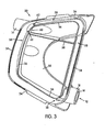
- the humidifier outlet 14 extends through the space 58 and provides an opening 60 within the internal wall structure 56.
- At least one aperture 62 is formed in the outlet tube 14 in a location between the side walls 54 and the internal wall structure 56, and is thus in communication with the space 58
- the gasket 22 is formed with a ledge receiving channel 68, which is defined on an outer side thereof by sealing flange 40.
- the ledge receiving channel 68 engages an exterior side of the ledge portion 48.
- the channel 68 also includes a plurality of sealing lips 70 that are configured to resiliently engage an interior surface of the ledge portion 48. Engagement of the flange 40 and lips 70 provides a resilient sealing connection between the gasket 22 and base 24.
- the bridge structure 50 serves to intermediately support the gasket 22. In particular, a downwardly facing surface of the channel structure 30 is vertically supported on an upwardly facing surface of the bridge structure 50.
- the gasket 22 is attached to the base 24, such that the ledge portion 48 is received within the flange 40.
- the top cover 20 is brought into engagement with the gasket 22, such that the internal wall structure 56 is received within a wall receiving channel 72 in the gasket 22.
- the internal wall structure 56 is engaged within the channel 72, thereby forming a resilient sealing connection with the gasket 22 and effectively enclosing space 58.
- the dividing wall structure 38 is received within the channel 30.
- the top cover 20 is then secured to the base 24, e.g., via sliding clips 74 on either side of the top cover 20, to ensure that the top cover 20 and base 24 remain together when the air within the humidifier is at a higher pressure than ambient pressure.
- Fig. 9 is a top view of the assembled humidifier 10.
- Figs. 10 and 11 are sectional views of the assembled humidifier 10 shown in Fig. 9 .
- an upwardly facing surface of the first section 26 of the gasket 22, a portion of the top wall 52, the divider wall structure 38, and portions of the internal wall structure 56 together define an upper chamber 76.
- the receptacle 42 of the base 24 together with a downwardly facing surface of the gasket 22 define a lower chamber 78.
- the upper chamber 76 is in communication with the inner tube 16 of the inlet 12 and the lower chamber 78 is in communication with the outlet 14 via the second apertures 34.
- the upper chamber 76 and the lower chamber 78 are in communication with each other via the first aperture 32. As shown in Fig. 11 , the space 58 is thus sealed by the gasket 22 to form an internal passage 80.
- the internal passage 80 is thus defined by cooperating surfaces of the top wall 52, side walls 54, gasket 22, and the internal wall structure 56.
- a predetermined maximum volume of water is poured into the receptacle 42 of the base 24, e.g., after removing the top cover 20 and the sealing gasket 22.
- the top cover 20 and the sealing gasket 22 are reattached to the base 24 after filling the receptacle 42.
- the volume of water 82 is held in the lower chamber 78.
- Air from the blower enters via the inner tube 16 of the inlet 12 and travels along the upper chamber 76 and into the first aperture 32. The air enters the lower chamber 78 where it is humidified by contact with the water, before exiting through apertures 34 in the gasket 22, and then out through outlet 14.
- the inlet tube 16, the first chamber 76, the aperture 32, the second chamber 78, the second apertures 34, and the outlet 14 effectively define an internal fluid passage, indicated at 99 in Fig. 12 , by which the breathable gas flows through the humidifier 10.
- the outer tube 18 is connected to a monitoring conduit in the NIPPV or CPAP apparatus for communication with a sensing device (e.g., pressure transducer, microphone, etc.) in the NIPPV or CPAP apparatus.
- a sensing device e.g., pressure transducer, microphone, etc.
- the aperture 62 ( Fig. 3 ) and the internal passage 80 ( Figs. 10 and 11 ) thus provide communication between the outlet 143 and the sensing device, which allows for monitoring of parameters of the flow of breathable gas between the mask and outlet 14, such as pressure and/or noise levels thereof.
- a correction factor which allows for a degree of signal attenuation within the supply conduit between the mask and outlet 14 may be used to estimate an actual signal level at the mask based on the level of the parameter sensed at outlet 14 and the flow delivered by the flow generator.
- the sensing device is associated with the NIPPV or CPAP apparatus blower for increasing or decreasing the output of the blower to the humidifier, as required.
- the parameter of the breathable gas flow at the humidifier outlet 16 during use can be monitored and the blower output can be adjusted as required.
- the humidifier outlet can be monitored without signal attenuation from the volume of water within the humidifier and/or the internal configuration of the humidifier and without inconvenient extra components.
- the at least one aperture 62 may be provided by a pair or more of apertures in the outlet tube 14 to decrease the likelihood of a water droplet from the humid air blocking a single aperture.
- the humidifier 10 is formed with the upper and lower chambers 76 and 78 to provide spill protection for the humidifier 10 as described in the co-pending applications incorporated above, as well as co-pending application WO-A-02/066106 , entitled “A Humidifier", filed on even date herewith
- a particular advantage of the preferred embodiment is convenience and usability. Patients, who may have poor dexterity, and clinicians are not burdened with manipulating small tubing. Further, cleaning and disinfection are also easier, because substantially the entire interior of the internal passage 80 is exposed when the humidifier is opened ( i.e ., when top cover 20 and gasket 22 are separated from each other). It is contemplated that materials for construction of the top cover 20, the gasket 22 and the base 24 may be chosen so as to enable various disinfecting or sterilizing methods to be used such as steam autoclaving, chemical cleaning and gamma ray sterilizing.
- the integral nature of the internal passage 80 significantly reduces componentry of the humidifier, which reduces manufacturing costs of the humidifier. This is particularly relevant when the top cover 20, gasket 22, and base 24 are formed from molded polymer materials, such as described above.
- the humidifier also provides for relatively simplistic assembly and disassembly. The ease of assembly provides further manufacturing cost savings, since there is very little time involved in assembling the components of the humidifier. Prior art humidifiers, which require use of mechanical fasteners, adhesives, connection of fittings and/or additional tubing may have substantially increased manufacturing costs. The ease of assembly and disassembly may also be advantageous for end users, such as patients and clinicians who regularly disassemble and assemble the humidifier, such as to fill and/or clean it, as discussed above.
- the humidifier 10 has a generally trapezoidal shape. It is contemplated that the humidifier 10 may also be configured with any other suitable shape, such as rectangular or semi-circular. It is also contemplated that the humidifier 10 may have any suitable dimensions. For example, the humidifier 10 may be configured with a height of about 9 cm, a width of 14 cm to 18 cm and a depth of about 12 cm.
- the outlet 14 may have an inner diameter of about 2 cm.
- the apertures 62 in the outlet 14 may have a diameter of about 2 mm.
- the inlet 14 may have an inner diameter of about 1.8 cm and the outer tube 18 may have an inner diameter of about 3 cm.
- the passage 80 may have an approximately rectangular section with a height of about 1 cm to 3 cm.
- the outlet 14 is connectable with an outlet conduit having a patient mask at one end.
- the passage 80 may be in communication with the humidifier outlet 14 at the patient mask via a third conduit, rather than through apertures 62.
- the third conduit can be integral with the outlet conduit or separate thereto.
- the third conduit may be internal or external of the outlet conduit.
- the present invention can be used in a humidifier which does not include the gasket 22.
- the passage 80 may be formed by having the internal protrusion 56 extending from the top wall 52 to the bottom wall 42 of the base 24.
- one of the internal walls of the passage 80 can be formed by a curved wall of the top cover, rather than the top and side wall(s) thereof.
- the internal protrusion can be L-shaped and attached to a humidifier wall to form the passage with the gasket.
- the passage 80 does not have to extend about the entire periphery of the humidifier 10 and can only extend about at least part thereof.
- the humidifier 10 may be used as a retrofit or add-on component for a CPAP apparatus.
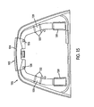
- an adapter or a connecting structure 100 ( Fig. 13 ) that is configured to connect between the NIPPV or CPAP apparatus and the humidifier 10.
- the connecting structure 100 includes a housing 102 that provides a generally horizontally extending receptacle 104 within which the humidifier 10 may be disposed.
- the housing 102 provides a base portion 106 that is configured to support the humidifier 10 thereon and a retaining portion 108 configured to secure the humidifier 10 in position.
- a retaining portion 108 configured to secure the humidifier 10 in position.
- the retaining portion 108 extends generally parallel to the base portion 106 and is spaced above the base portion 106.
- the humidifier 10 may be formed with the recess 110 ( Fig. 1 ) that is open and of a complimentary shape to receive the retaining portion 108 therein.
- a forward portion of the base portion 106 may include generally upwardly open recesses 134, which will be discussed further below.
- a humidifier may include a securing mechanism 122.
- the securing mechanism 122 includes a resiliently biased pull member 124 that is formed with one or more locking lugs 126 extending generally downwardly therefrom.
- the pull member 124 is disposed at a forward end (assuming the rearward end of the humidifier 120 is adjacent the connecting structure 100) of the humidifier 120 and is resiliently biased by a pair of resilient legs 128. Rearward portions of the legs 128 are relatively securely retained within corresponding pocket structures 130 provided on a bottom side of the humidifier 120.
- Ribs 132 extend downwardly from the bottom side of the humidifier 120 and engage an intermediary portion of the legs 128 to define a space between the resilient legs 128 and the bottom side of the humidifier 120. In this manner, the pull member 124 is biased generally downwardly by the resilient legs 128, but may be manually moved (e.g., pulled) upward against a resilient bias of the legs 128.
- the base portion 106 may include the generally upwardly open lug receiving recesses 134 ( Fig. 14 ) within which the lugs 126 may be disposed when the humidifier 120 is disposed within the receptacle 104.
- the legs 128 resiliently bias the lugs 126 into recesses 134.
- the lugs 126 and recesses 134 thereby secure the humidifier 120 within the receptacle 104.
- the pull member 124 is pulled upwardly to withdraw the lugs 126 from the recesses 134.
- the humidifier 120 may then be pulled generally horizontally out of the receptacle 104.
- Fig. 16 shows a rearward side of the connecting structure 100.
- the rearward side of the connecting structure 100 provides a retaining mechanism 140 to secure the connecting structure 100 to the CPAP apparatus.
- the retaining mechanism 140 may include a series of apertures 142 within the rearward portion of the housing 102.
- the apertures 142 may receive therein, for example, prongs or tabs (not shown) provided by the NIPPV or CPAP apparatus.
- a locking member 144 may be provided that is resiliently biased toward a position that partially encloses the respective aperture 142.
- Fig. 16 shows a rearward side of the connecting structure 100.
- the rearward side of the connecting structure 100 provides a retaining mechanism 140 to secure the connecting structure 100 to the CPAP apparatus.
- the retaining mechanism 140 may include a series of apertures 142 within the rearward portion of the housing 102.
- the apertures 142 may receive therein, for example, prongs or tabs (not shown) provided by the NIPPV
- a button structure 146 may be coupled to the locking members 144, such that manual movement of the button structure 146 moves the locking members 144 out of their biased positions to substantially fully open the apertures 142. It is contemplated that the tabs or prongs on the CPAP apparatus are provided with a groove therein such that when positioned within the apertures 142, the locking members 144 engage within respective grooves to thereby securely and detachably retain the connecting structure 100 to the CPAP apparatus.
- the housing 102 of the connecting structure 100 may be provided with an opening 148 that allows the inlet 12 of the humidifier to extend therethrough so as to be connected to the CPAP apparatus.
- the connecting structure 150 may include a heater 152.
- the connecting structure 150 may include a housing 154 that provides a base portion 156 and retaining portion 158, similar to the housing 102 described above.
- the retaining portion 158 may include a controller such as a knob or other selecting device 160 thereon to control a heat setting of the heater 152.
- the controller 160 may include a display device, such as an LCD screen.
- the base portion 156 may include a heating element 162 thereon.
- the heating element 162 may be in the form of a substantially flat plate-like resistance heater, which heat generated thereby may be directly controlled by the controller 160.
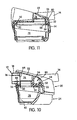
- the humidifier 170 is disposed within a receptacle 172 provided by the housing 154. It is contemplated that the humidifier 170 has the same basic construction as the humidifiers 10 and 120 described above. However, the humidifier 170 may include a heating plate 174 to facilitate heating of the liquid contained therein. In particular, an opening 176 is provided within a bottom wall 178 of the humidifier 170. The heating plate 174 is shaped to fit within the opening 176, as shown in Fig. 20 . As shown in more detail in Fig. 21 , the heating plate 174 includes an upstanding peripheral wall 180 which includes an outwardly extending peripheral lip 182.
- a resilient seal member 184 is disposed about an outer periphery of the peripheral wall 180 in contact with the peripheral lip 182.
- a ring-like retaining member 186 may be press fit onto the peripheral wall 180 to retain the seal 184 in position on the peripheral wall 180.
- the retaining member 186 includes an outwardly extending flange structure 188.
- the seal 184 is disposed between the peripheral lip 182 and flange structure 188. It is contemplated that the retaining member 186 may be press fit onto the heating plate 174, as described above, or may be formed in one piece therewith.
- the bottom wall 178 of the humidifier 170 is formed with an annular upstanding flange 190 which receives the heating plate 174.
- the flange 190 may be slightly tapered inwardly in the upward direction to ease insertion of the heating plate 174. As shown, the flange 190 may include a generally horizontally extending lip structure 192 that vertically retains the heating plate 174.
- a bottom surface of the heating plate 174 is in contact with an upper surface of the heating element 162.
- a heat generated by the heating element 162 is conductively transferred to the heating plate 174.
- the liquid within the humidifier 170 is exposed to an upper surface of the heating plate 174 and conducts heat therefrom. It is contemplated that a temperature of the liquid within the humidifier 170 may be controlled by manipulation of the controller 160.
- the heating element 162 may be upwardly resiliently biased to ensure adequate contact between the heating element 162 and the heating plate 174.
- a rearward portion of the connecting structure 150 may include a plurality of generally outwardly extending contact elements 194. It is contemplated that the contact element 194 may communicate with a power supply within the CPAP apparatus and/or a controller and/or sensors. In this manner, power may be delivered to the heater 152 directly from the CPAP apparatus. Additionally, a controller within the CPAP apparatus itself may control the heater 152. Furthermore, it is contemplated that sensors within the CPAP apparatus may monitor a heat output of the heater 152. Moreover, it may be possible for a CPAP apparatus to automatically adjust a heat output of the heater 152 based on a measured temperature thereof or of the water within the humidifier or of the breathable air exiting the humidifier.
Landscapes
- Health & Medical Sciences (AREA)
- Emergency Medicine (AREA)
- Pulmonology (AREA)
- Engineering & Computer Science (AREA)
- Anesthesiology (AREA)
- Biomedical Technology (AREA)
- Heart & Thoracic Surgery (AREA)
- Hematology (AREA)
- Life Sciences & Earth Sciences (AREA)
- Animal Behavior & Ethology (AREA)
- General Health & Medical Sciences (AREA)
- Public Health (AREA)
- Veterinary Medicine (AREA)
- Air Humidification (AREA)
Description
- The present invention relates to a humidifier as defined in claim 1.
US 4993411 is considered the closest prior art. - Obstructive Sleep Apnea (OSA) may be treated by the application of nasal Continuous Positive Airway Pressure (CPAP). CPAP treatment provides pressurized air or other breathable gas to the entrance of a patient's airways at a pressure elevated above atmospheric pressure. It is also known for the level of treatment pressure to vary from breath to breath in accordance with patient need, that form of CPAP being known as "automatically adjusting nasal CPAP treatment".
US 5,704,345 describes a method and apparatus for continuously adjusting the CPAP pressure while monitoring patient respiration air flow and pressure via a pressure sensor communicated with the supply conduit extending between the mask and blower. In particular, the pressure sensor is in communication with the supply conduit via an additional segment of conduit extending between the supply conduit and pressure sensor. - Alternatively, as illustrated schematically in
Fig. 23 , a CPAP apparatus, indicated at 500, may include ablower 502 connected to amask 504 viasupply conduit 506 and apressure transducer 508 is in communication with themask 504 itself via amonitoring conduit 510. Thepressure transducer 508 is located within theCPAP apparatus 500 and is in communication with aCPU 512. TheCPU 512 is connected to theblower 502 in such a manner to be capable of controlling an output thereof based on parameters sensed by thepressure transducer 508. - In one embodiment of
US 5,245,995 , illustrated schematically inFig. 24 , apressure transducer 514 is incorporated into themask 504 itself and is in communication with theCPU 512 via awire 516. In another embodiment ofUS 5,245,995 , a microphone is connected to the mask and in communication with the CPU via a wire. - Some of the embodiments described above and disclosed in
US 5,704,345 andUS 5,245,995 may utilize additional tubing or wiring to connect the monitoring device (e.g., pressure transducer and/or microphone) on the mask or supply conduit to the controller within the CPAP apparatus. These arrangements are disadvantageous, however, since the additional tubes or wires are difficult to manipulate and can tangle. Additionally, embodiments incorporating a monitoring device into the mask itself are often uncomfortable for the users. - Other CPAP apparatus embodiments utilize a monitoring device within the blower itself, such as schematically illustrated in
Fig. 25 . Due to the relative proximity between theblower 502 andCPU 512, the monitoring device 508 (e.g., pressure transducer) may be communicated with theCPU 512 without necessitating use of superfluous lengths of additional tubing. However, signals measured in theblower 502 must be corrected with a corresponding correction factor for any changes which may occur in the signal's communication from themask 504, along thesupply conduit 506 to theblower 502. For example, when using an accessory such as a humidifier indicated at 520 inFig. 26 , which may behave as a muffler attenuating the AC component of the pressure signal, theCPU 512 may not be able to correct for the added attenuation, for example, if the level of attenuation is variable, such as due to varying levels of liquid within the humidifier. Alternatively, the correction factor may need to be altered for use with an accessory such as a humidifier. However, continued correction for accessories may degrade the accuracy of the corrected value. - The use of an accessory such as a humidifier may be desirable, however. Some patients find treatment more comfortable if the air from the blower outlet is humidified, which can be achieved by placing a humidifier in between the blower and the supply conduit. The humidifier includes a chamber containing a volume of water, which water acts to humidify the breathable air flowing through the humidifier. However as discussed above, the presence of the humidifier in the air flow path alters and may degrade the air pressure signal which can be detected by transducers in the blower.
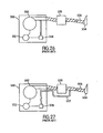
- One embodiment of
US 5,537,997 , schematically illustrated inFig. 27 , discloses using asecond conduit 522 to connect apressure transducer 508 inside theCPAP apparatus 500 to a point in thesupply conduit 506 between thehumidifier 520 and themask 504. However, thesecond conduit 522 represents additional componentry which can be an inconvenience for the patient and the clinician administering use of the CPAP apparatus. InUS 5,537,997 , thesecond conduit 522 extends externally of thehumidifier 520. Such extra tubing may tangle easily and become disconnected. This is disadvantageous, since typical patients have poor dexterity and the pressure and/or snore signal is used to maintain the intended therapy. - Apparatuses utilizing additional tubing are also disadvantageous, as cleaning and disinfection may be difficult. Disinfection prevents cross-infection of patients using a shared blower.
- Another attempt to diminish signal attenuation is schematically illustrated in
Figs. 28 and 29 and are disclosed inUS Patent Application Ser. No. 09/099,665 In the embodiment ofFigures 28-29 , the humidifier can be removed and replaced with appropriate tubing and/or a conduitFig. 29 shows the humidifier after its removal, with the appropriate tubing/conduit in its place. Like he embodiment ofFig. 27 , the pressure transducer inFig. 28 is between the humidifier and the mask, which avoids routing the signal through the humidifier. - It is one aspect of the present invention to substantially overcome or at least ameliorate the above disadvantages or at least provide a useful alternative.
- It is another aspect to provide a humidifier for a CPAP apparatus with first and second passages, one of which avoids the degradation of measurement signals typically incurred due to attenuation within the humidifier.
- It is another aspect to provide a humidifier for a CPAP apparatus with first and second passages, wherein the first and second passages are formed integrally with the humidifier.
- It is yet another aspect to provide a humidifier for a CPAP apparatus which has separable componentry that separates to substantially entirely expose the interiors of the components.
- It is another aspect to provide a humidifier for a CPAP apparatus that is relatively easier to manufacture than prior art humidifiers.
- It is another aspect to provide a humidifier for a CPAP apparatus that is relatively easier to assemble than prior art humidifiers.
- It is another aspect to provide a humidifier for a CPAP apparatus that is relatively easier to disassemble than prior art humidifiers.
- The object(s) underlying the present invention is/are solved by the combination of features according to the independent claim while the dependent claims refer to preferred embodiments according to the present invention..
- A humidifier is discussed, the humidifier including a first humidifier part, a second humidifier part connectable with the first humidifier part, and a sealing gasket disposed between the first and second humidifier parts. The second humidifier part is configured to hold a volume of liquid therein and the first and second humidifier parts and the sealing gasket define first and second internal passages within the humidifier. The first passage is disposed so as to be exposed to a surface of the volume of liquid and the second passage is isolated from at least one of the first passage and the surface of the volume of liquid. The second passage is configured to communicated with a pressure and/or sound sensing device.
- In this manner, a pressure signal may be detected within the isolated second passage without degrading the signal by attenuation within the first passage.
- It is contemplated that the first and second humidifier parts may be separable from one another in a manner such that walls of the first and second internal passages may be substantially entirely exposed.
- In this manner, the first and second humidifier parts may be separated so as to substantially entirely expose the interiors thereof in order to easily clean and disinfect the interiors.
- A portion of an internal surface of the first humidifier part may define at least one internal wall of the second internal passage.
- The first humidifier part may include a top wall, a peripherally extending side wall extending downwardly from the top wall, and an internal wall structure extending downwardly from the top wall generally parallel to and inwardly spaced from the peripherally extending side wall. The internal wall structure, portions of the top wall, and portions of the peripherally extending side walls may define corresponding internal walls of the internal passage.
- A portion of a surface of the sealing member may define a corresponding internal wall of the internal passage.
- The first humidifier part may include first and second inlet tubes and an outlet tube, the first inlet tube and outlet tube may be communicated with the first internal passage, and the second inlet tube and the outlet tube may be communicated with the second internal passage.
- The outlet tube may extend from the internal wall structure of the first humidifier part in such a manner to be communicated with the first internal passage to outside of the humidifier and the second internal passage may be communicated with the outlet tube via at least one aperture formed in the outlet tube.
- The at least one aperture may be provided by a pair of apertures.
- The first inlet tube may extend from the internal wall structure of the first humidifier part in such a manner to be communicated with the first internal passage to outside of the humidifier, and the second inlet tube may extend from the peripherally extending side wall of the first humidifier part in such a manner to be communicated with the second internal passage to the aperture within the outlet tube.
- The second inlet tube may be coaxial with and surround the first inlet tube.
- The first and second humidifier parts may be formed from a relatively rigid polymer material and the sealing gasket may be formed from a relatively resilient material.
- It is also contemplated that the humidifier may include a heater configured to raise a temperature of the volume of liquid within the humidifier.
- A CPAP apparatus is discussed, the CPAP apparatus including a humidifier of the embodiment described above.
- A method of determining pressure within a conduit supplying breathable gas from a CPAP apparatus to a patient mask is discussed. The method includes providing a humidifier with first and second internal passages therein. The first passage is disposed within the humidifier so as to be exposed to a surface of a volume of liquid present within the humidifier and the second passage is isolated from the first passage. The method includes supplying the breathable gas to a first inlet tube of the humidifier in communication with the first internal passage so that breathable gas flowing therethrough is humidified by contact with the volume of liquid and is communicated with an outlet tube of the humidifier. Furthermore, the method includes providing an aperture within the outlet tube in communication with the second internal passage and measuring a pressure within the second internal passage to determine pressure within the outlet tube.
- Although certain embodiments of the invention are illustrated and described herein as having certain features, one skilled in the art would recognize that alternative embodiments of the invention could be provided based on at least one or more features, either individually or in combination, of the illustrated and described embodiments.
- The benefits of the present invention will be readily appreciated and understood from consideration of the following detailed description of embodiments of this invention, when taken with the accompanying drawings, wherein:
-
Fig. 1 is a perspective view of a humidifier according to one embodiment of the present invention; -
Fig. 2 is an exploded perspective view of the humidifier shown inFig. 1 ; -
Fig. 3 is a bottom perspective view of a top cover of the humidifier shown inFig. 1 ; -
Fig. 4 is a top view of the top cover of the humidifier shown inFig. 1 ; -
Fig. 5 is a cross-sectional view through line 5-5 ofFig. 4 ; -
Fig. 6 is a cross sectional view through line 6-6 ofFig. 4 ; -
Fig. 7 is a cross-sectional view through line 7-7 ofFig. 4 ; -
Fig. 8 is a front perspective partial sectional view of the assembled humidifier shown inFig. 1 ; -
Fig. 9 is a top view of the assembled humidifier shown inFig. 1 : -
Fig. 10 is a cross-sectional view through line 10-10 ofFig. 9 ; -
Fig. 11 is a cross-sectional view through line 11-11 ofFig. 9 ; -
Fig. 12 is a perspective view of the humidifier schematically showing the direction of travel of breathable gas from the blower through the humidifier; -
Fig. 13 is a perspective view of a humidifier and connecting structure according to another embodiment of the present invention; -
Fig. 14 is a perspective view of the connecting structure shown inFig. 13 ; -
Fig. 15 is a bottom view of the humidifier shown inFig. 13 ; -
Fig. 16 is a rear perspective view of the humidifier and connecting structure shown inFig. 13 ; -
Fig. 17 is a bottom perspective view of the connecting structure shown inFig. 13 ; -
Fig. 18 is a perspective view of a humidifier and heater according to another embodiment of the present invention; -
Fig. 19 is a perspective view of the heater shown inFig. 18 ; -
Fig. 20 is a bottom view of the humidifier shown inFig. 18 ; -
Fig. 21 is a cross-sectional view taken along line 23-23 inFig. 20 ; -
Fig. 22 is a rear perspective view of the humidifier and heater shown inFig. 18 ; -
Figs. 23-27 are schematic views of prior art CPAP apparatuses; and -
Figs. 28-29 are schematic views of related art CPAP apparatuses. -
Fig. 1 shows one contemplated embodiment of ahumidifier 10 according to the present invention. Thehumidifier 10 includes aninlet 12 and anoutlet 14, both being communicated with an interior of thehumidifier 10. Thehumidifier inlet 12 is adapted for detachable connection to an output of a CPAP or NIPPV (Non-invasive Positive Pressure Ventilation) apparatus (not shown), which includes a blower for providing a supply of pressurized breathable gas to thehumidifier 10. Theoutlet 14 is connectable to an outlet conduit (not shown) leading to and communicated with a patient, e.g., via a mask, and a monitoring conduit in communication with a pressure and/or sound sensing device (e.g., pressure transducer, microphone, etc.) within the CPAP or NIPPV apparatus. Air from the blower enters theinlet 12 and collects moisture through contact with the water within thehumidifier 10, before continuing on to theoutlet 14 and to the patient. Thehumidifier 10 includes a first humidifier part, ortop cover 20 and a second humidifier part, orbase 24, which are held together, for example, with a pair of sliding retaining clips 74. It is contemplated that thetop cover 20 andbase 24 may alternatively be secured to one another by, for example, having a snap-fit configuration, or use of other suitable fastening arrangements. Additionally, thetop cover 20 may be formed with arecess 110 therein, discussed further below. - As shown in
Fig. 2 , thehumidifier 10 includes agasket 22 between thetop cover 20 andbase 24. Thetop cover 20 may be formed from a relatively rigid polymer material, such as polysulfone (for example, grade UDEL P1700, manufactured by BP Amoco Polymers) and includes theinlet 12 and theoutlet 14. Thegasket 22 may be formed of a relatively resilient material, such as silicone rubber (for example, SILASTIC 94-595-HC, manufactured by Dow Coming), and is divided into first andsecond sections channel structure 30. Thefirst section 26 may include a first vertically extendingaperture 32. Thesecond section 28 may include a plurality of second vertically extendingapertures 34, which are separated from each other byribs 36. Thegasket 22 may include a stealingflange 40 formed about a periphery thereof. - It is contemplated that the base 24 may be formed from a relatively rigid polymer material, such as that used to form the
top cover 20, and includes areceptacle 42 formed therewithin, abottom wall 44,side walls 46 extending upwardly from thebottom wall 44, and aledge portion 48. The base 24 may also include aremovable bridge structure 50. - As shown in
Fig. 3 , an interior of thetop cover 20 may include adivider wall structure 38 that is positioned corresponding to thechannel structure 30 of thegasket 22. The interior of thetop cover 20 may also be formed with aninternal wall structure 56, discussed below. As also shown inFig. 3 , thehumidifier inlet 12 includes a pair of concentric tubes, aninner tube 16 and anouter tube 18. -
Fig. 4 illustrates a general arrangement of theinlet 12 andoutlet 14 relative to thetop cover 20. As shown, theinlet 12 andoutlet 14 are disposed on opposite sides of thetop cover 20 and at opposite ends thereof. Also, theinlet 12 andoutlet 14 may be formed to extend generally parallel to one another. However, theinlet 12 andoutlet 14 may alternatively be formed in any other relative arrangement. Thetop cover 20 includes atop wall 52,side walls 54 extending generally downwardly from thetop wall 52, and theinternal wall structure 56 also extending downwardly from thetop wall 52. As shown inFigs. 5 and 6 , theinternal wall structure 56 is generally parallel to and spaced inwardly from theside walls 54 to define aspace 58 therebetween. Referring toFig. 5 , theinner tube 16 of theinlet 12 extends through thespace 58 and provides anopening 64 within theinternal wall structure 56 so as to be communicated with the interior of thehumidifier 10. Theouter tube 18 may be coaxial with and may surround theinner tube 16. Theouter tube 18 provides anopening 66 within theside wall 54 and communicates with thespace 58. In lieu of theconcentric tubes inlet 12 may be provided with a pair of inlet tubes, which communicate with the interior of thehumidifier 10 andspace 58, respectively, that are not concentric with one another. For example, it is contemplated that the inlet tubes may be arranged in a parallel, side-by-side manner, or any other suitable manner. It is also contemplated that the inlet tubes may be integrally formed, mechanically fastened to one another, or completely separate components. As shown inFig. 7 , thehumidifier outlet 14 extends through thespace 58 and provides anopening 60 within theinternal wall structure 56. At least oneaperture 62 is formed in theoutlet tube 14 in a location between theside walls 54 and theinternal wall structure 56, and is thus in communication with thespace 58 - As shown in
Fig. 8 , thegasket 22 is formed with aledge receiving channel 68, which is defined on an outer side thereof by sealingflange 40. Theledge receiving channel 68 engages an exterior side of theledge portion 48. Thechannel 68 also includes a plurality of sealinglips 70 that are configured to resiliently engage an interior surface of theledge portion 48. Engagement of theflange 40 andlips 70 provides a resilient sealing connection between thegasket 22 andbase 24. As also shown, thebridge structure 50 serves to intermediately support thegasket 22. In particular, a downwardly facing surface of thechannel structure 30 is vertically supported on an upwardly facing surface of thebridge structure 50. - To assemble the
humidifier 10, thegasket 22 is attached to thebase 24, such that theledge portion 48 is received within theflange 40. Thetop cover 20 is brought into engagement with thegasket 22, such that theinternal wall structure 56 is received within awall receiving channel 72 in thegasket 22. Theinternal wall structure 56 is engaged within thechannel 72, thereby forming a resilient sealing connection with thegasket 22 and effectively enclosingspace 58. Additionally, the dividingwall structure 38 is received within thechannel 30. As discussed above and shown inFig. 1 , thetop cover 20 is then secured to thebase 24, e.g., via slidingclips 74 on either side of thetop cover 20, to ensure that thetop cover 20 andbase 24 remain together when the air within the humidifier is at a higher pressure than ambient pressure. -
Fig. 9 is a top view of the assembledhumidifier 10.Figs. 10 and 11 are sectional views of the assembledhumidifier 10 shown inFig. 9 . As shown inFig. 10 , an upwardly facing surface of thefirst section 26 of thegasket 22, a portion of thetop wall 52, thedivider wall structure 38, and portions of theinternal wall structure 56 together define anupper chamber 76. Thereceptacle 42 of the base 24 together with a downwardly facing surface of thegasket 22 define alower chamber 78. Referring back toFig. 8 , theupper chamber 76 is in communication with theinner tube 16 of theinlet 12 and thelower chamber 78 is in communication with theoutlet 14 via thesecond apertures 34. Theupper chamber 76 and thelower chamber 78 are in communication with each other via thefirst aperture 32. As shown inFig. 11 , thespace 58 is thus sealed by thegasket 22 to form aninternal passage 80. Theinternal passage 80 is thus defined by cooperating surfaces of thetop wall 52,side walls 54,gasket 22, and theinternal wall structure 56. - In use, a predetermined maximum volume of water, indicated at 82 in
Fig. 12 , is poured into thereceptacle 42 of thebase 24, e.g., after removing thetop cover 20 and the sealinggasket 22. Thetop cover 20 and the sealinggasket 22 are reattached to the base 24 after filling thereceptacle 42. In this manner, the volume ofwater 82 is held in thelower chamber 78. Air from the blower enters via theinner tube 16 of theinlet 12 and travels along theupper chamber 76 and into thefirst aperture 32. The air enters thelower chamber 78 where it is humidified by contact with the water, before exiting throughapertures 34 in thegasket 22, and then out throughoutlet 14. It is contemplated that theinlet tube 16, thefirst chamber 76, theaperture 32, thesecond chamber 78, thesecond apertures 34, and theoutlet 14 effectively define an internal fluid passage, indicated at 99 inFig. 12 , by which the breathable gas flows through thehumidifier 10. - The
outer tube 18 is connected to a monitoring conduit in the NIPPV or CPAP apparatus for communication with a sensing device (e.g., pressure transducer, microphone, etc.) in the NIPPV or CPAP apparatus. The aperture 62 (Fig. 3 ) and the internal passage 80 (Figs. 10 and 11 ) thus provide communication between the outlet 143 and the sensing device, which allows for monitoring of parameters of the flow of breathable gas between the mask andoutlet 14, such as pressure and/or noise levels thereof. A correction factor which allows for a degree of signal attenuation within the supply conduit between the mask andoutlet 14 may be used to estimate an actual signal level at the mask based on the level of the parameter sensed atoutlet 14 and the flow delivered by the flow generator. The sensing device is associated with the NIPPV or CPAP apparatus blower for increasing or decreasing the output of the blower to the humidifier, as required. Thus, the parameter of the breathable gas flow at thehumidifier outlet 16 during use can be monitored and the blower output can be adjusted as required. Additionally, the humidifier outlet can be monitored without signal attenuation from the volume of water within the humidifier and/or the internal configuration of the humidifier and without inconvenient extra components. - It is contemplated that the at least one
aperture 62 may be provided by a pair or more of apertures in theoutlet tube 14 to decrease the likelihood of a water droplet from the humid air blocking a single aperture. Thehumidifier 10 is formed with the upper andlower chambers humidifier 10 as described in the co-pending applications incorporated above, as well as co-pending applicationWO-A-02/066106 - A particular advantage of the preferred embodiment is convenience and usability. Patients, who may have poor dexterity, and clinicians are not burdened with manipulating small tubing. Further, cleaning and disinfection are also easier, because substantially the entire interior of the
internal passage 80 is exposed when the humidifier is opened (i.e., whentop cover 20 andgasket 22 are separated from each other). It is contemplated that materials for construction of thetop cover 20, thegasket 22 and the base 24 may be chosen so as to enable various disinfecting or sterilizing methods to be used such as steam autoclaving, chemical cleaning and gamma ray sterilizing. - Additionally, the integral nature of the
internal passage 80 significantly reduces componentry of the humidifier, which reduces manufacturing costs of the humidifier. This is particularly relevant when thetop cover 20,gasket 22, andbase 24 are formed from molded polymer materials, such as described above. The humidifier also provides for relatively simplistic assembly and disassembly. The ease of assembly provides further manufacturing cost savings, since there is very little time involved in assembling the components of the humidifier. Prior art humidifiers, which require use of mechanical fasteners, adhesives, connection of fittings and/or additional tubing may have substantially increased manufacturing costs. The ease of assembly and disassembly may also be advantageous for end users, such as patients and clinicians who regularly disassemble and assemble the humidifier, such as to fill and/or clean it, as discussed above. - In the illustrated embodiment, the
humidifier 10 has a generally trapezoidal shape. It is contemplated that thehumidifier 10 may also be configured with any other suitable shape, such as rectangular or semi-circular. It is also contemplated that thehumidifier 10 may have any suitable dimensions. For example, thehumidifier 10 may be configured with a height of about 9 cm, a width of 14 cm to 18 cm and a depth of about 12 cm. Theoutlet 14 may have an inner diameter of about 2 cm. Theapertures 62 in theoutlet 14 may have a diameter of about 2 mm. Theinlet 14 may have an inner diameter of about 1.8 cm and theouter tube 18 may have an inner diameter of about 3 cm. Thepassage 80 may have an approximately rectangular section with a height of about 1 cm to 3 cm. - As mentioned, the
outlet 14 is connectable with an outlet conduit having a patient mask at one end. In an alternative embodiment, thepassage 80 may be in communication with thehumidifier outlet 14 at the patient mask via a third conduit, rather than throughapertures 62. The third conduit can be integral with the outlet conduit or separate thereto. The third conduit may be internal or external of the outlet conduit. - Although preferred forms of the present invention have been described, it will be apparent to persons skilled in the art that modifications to the above embodiments can be made. For example, the present invention can be used in a humidifier which does not include the
gasket 22. In such an embodiment, thepassage 80 may be formed by having theinternal protrusion 56 extending from thetop wall 52 to thebottom wall 42 of thebase 24. In another alternative embodiment, one of the internal walls of thepassage 80 can be formed by a curved wall of the top cover, rather than the top and side wall(s) thereof. As a further alternative, the internal protrusion can be L-shaped and attached to a humidifier wall to form the passage with the gasket. Also, thepassage 80 does not have to extend about the entire periphery of thehumidifier 10 and can only extend about at least part thereof. - It is contemplated that the
humidifier 10 may be used as a retrofit or add-on component for a CPAP apparatus. To facilitate this usage, it may be preferable to provide an adapter or a connecting structure 100 (Fig. 13 ) that is configured to connect between the NIPPV or CPAP apparatus and thehumidifier 10. As shown inFig. 13 , the connectingstructure 100 includes ahousing 102 that provides a generally horizontally extendingreceptacle 104 within which thehumidifier 10 may be disposed. Thehousing 102 provides abase portion 106 that is configured to support thehumidifier 10 thereon and a retainingportion 108 configured to secure thehumidifier 10 in position. As shown inFig. 14 , the retainingportion 108 extends generally parallel to thebase portion 106 and is spaced above thebase portion 106. As discussed above, thehumidifier 10 may be formed with the recess 110 (Fig. 1 ) that is open and of a complimentary shape to receive the retainingportion 108 therein. A forward portion of thebase portion 106 may include generally upwardlyopen recesses 134, which will be discussed further below. - To facilitate connection of the
humidifier 10 to the connectingstructure 100, it is contemplated that another embodiment of a humidifier, indicated at 120 inFig. 15 , may include asecuring mechanism 122. As shown, thesecuring mechanism 122 includes a resiliently biased pull member 124 that is formed with one or more locking lugs 126 extending generally downwardly therefrom. The pull member 124 is disposed at a forward end (assuming the rearward end of thehumidifier 120 is adjacent the connecting structure 100) of thehumidifier 120 and is resiliently biased by a pair ofresilient legs 128. Rearward portions of thelegs 128 are relatively securely retained within correspondingpocket structures 130 provided on a bottom side of thehumidifier 120.Ribs 132 extend downwardly from the bottom side of thehumidifier 120 and engage an intermediary portion of thelegs 128 to define a space between theresilient legs 128 and the bottom side of thehumidifier 120. In this manner, the pull member 124 is biased generally downwardly by theresilient legs 128, but may be manually moved (e.g., pulled) upward against a resilient bias of thelegs 128. - As discussed above, the
base portion 106 may include the generally upwardly open lug receiving recesses 134 (Fig. 14 ) within which thelugs 126 may be disposed when thehumidifier 120 is disposed within thereceptacle 104. As thehumidifier 120 is inserted withinreceptacle 104, thelegs 128 resiliently bias thelugs 126 intorecesses 134. Thelugs 126 and recesses 134 thereby secure thehumidifier 120 within thereceptacle 104. To remove thehumidifier 120 from thereceptacle 104, the pull member 124 is pulled upwardly to withdraw thelugs 126 from therecesses 134. Thehumidifier 120 may then be pulled generally horizontally out of thereceptacle 104. -
Fig. 16 shows a rearward side of the connectingstructure 100. The rearward side of the connectingstructure 100 provides aretaining mechanism 140 to secure the connectingstructure 100 to the CPAP apparatus. Theretaining mechanism 140 may include a series ofapertures 142 within the rearward portion of thehousing 102. Theapertures 142 may receive therein, for example, prongs or tabs (not shown) provided by the NIPPV or CPAP apparatus. As shown inFig. 17 , within eachaperture 142, a lockingmember 144 may be provided that is resiliently biased toward a position that partially encloses therespective aperture 142. As also shown inFig. 17 , abutton structure 146 may be coupled to the lockingmembers 144, such that manual movement of thebutton structure 146 moves the lockingmembers 144 out of their biased positions to substantially fully open theapertures 142. It is contemplated that the tabs or prongs on the CPAP apparatus are provided with a groove therein such that when positioned within theapertures 142, the lockingmembers 144 engage within respective grooves to thereby securely and detachably retain the connectingstructure 100 to the CPAP apparatus. - Referring back to
Fig. 16 , thehousing 102 of the connectingstructure 100 may be provided with anopening 148 that allows theinlet 12 of the humidifier to extend therethrough so as to be connected to the CPAP apparatus. - As discussed previously, in certain circumstances, it may be desirable to provide heated humid air to the respirator mask. Accordingly, another embodiment of the connecting structure, indicated at 150 in
Fig. 18 , may include aheater 152. The connectingstructure 150 may include ahousing 154 that provides abase portion 156 and retainingportion 158, similar to thehousing 102 described above. As shown inFig. 18 , the retainingportion 158 may include a controller such as a knob or other selectingdevice 160 thereon to control a heat setting of theheater 152. It is also contemplated that thecontroller 160 may include a display device, such as an LCD screen. - As shown in
Fig. 19 , thebase portion 156 may include aheating element 162 thereon. Theheating element 162 may be in the form of a substantially flat plate-like resistance heater, which heat generated thereby may be directly controlled by thecontroller 160. - As shown in
Fig. 20 , another embodiment of the humidifier is indicated at 170. Thehumidifier 170 is disposed within areceptacle 172 provided by thehousing 154. It is contemplated that thehumidifier 170 has the same basic construction as thehumidifiers humidifier 170 may include aheating plate 174 to facilitate heating of the liquid contained therein. In particular, anopening 176 is provided within abottom wall 178 of thehumidifier 170. Theheating plate 174 is shaped to fit within theopening 176, as shown inFig. 20 . As shown in more detail inFig. 21 , theheating plate 174 includes an upstandingperipheral wall 180 which includes an outwardly extendingperipheral lip 182. Aresilient seal member 184 is disposed about an outer periphery of theperipheral wall 180 in contact with theperipheral lip 182. A ring-like retaining member 186 may be press fit onto theperipheral wall 180 to retain theseal 184 in position on theperipheral wall 180. The retainingmember 186 includes an outwardly extendingflange structure 188. Theseal 184 is disposed between theperipheral lip 182 andflange structure 188. It is contemplated that the retainingmember 186 may be press fit onto theheating plate 174, as described above, or may be formed in one piece therewith. Thebottom wall 178 of thehumidifier 170 is formed with an annularupstanding flange 190 which receives theheating plate 174. It is contemplated that theflange 190 may be slightly tapered inwardly in the upward direction to ease insertion of theheating plate 174. As shown, theflange 190 may include a generally horizontally extendinglip structure 192 that vertically retains theheating plate 174. - Referring to
Figs. 19-21 , with thehumidifier 170 in position within thereceptacle 172, a bottom surface of theheating plate 174 is in contact with an upper surface of theheating element 162. In this manner, a heat generated by theheating element 162 is conductively transferred to theheating plate 174. The liquid within thehumidifier 170 is exposed to an upper surface of theheating plate 174 and conducts heat therefrom. It is contemplated that a temperature of the liquid within thehumidifier 170 may be controlled by manipulation of thecontroller 160. - It is also contemplated that the
heating element 162 may be upwardly resiliently biased to ensure adequate contact between theheating element 162 and theheating plate 174. - As shown in
Fig. 22 , a rearward portion of the connectingstructure 150 may include a plurality of generally outwardly extendingcontact elements 194. It is contemplated that thecontact element 194 may communicate with a power supply within the CPAP apparatus and/or a controller and/or sensors. In this manner, power may be delivered to theheater 152 directly from the CPAP apparatus. Additionally, a controller within the CPAP apparatus itself may control theheater 152. Furthermore, it is contemplated that sensors within the CPAP apparatus may monitor a heat output of theheater 152. Moreover, it may be possible for a CPAP apparatus to automatically adjust a heat output of theheater 152 based on a measured temperature thereof or of the water within the humidifier or of the breathable air exiting the humidifier.
Claims (12)
- A humidifier (10) comprising:a first humidifier part (20);a second humidifier part (24) connectable with the first humidifier part (20);the second humidifier part (24) being configured to hold a volume of liquid therein; and,first and second internal passages (99, 80) within the humidifier (10);the first passage (99) extending from an inlet, through a receptacle (42) of the second humidifier part configured to hold the volume of liquid, and to an outlet;the second passage (80) extending from a second inlet to the outlet;the first passage (99) being disposed so as to be exposed to a surface of said volume of liquid when held in the second humidifier part (24);the second passage (80) being configured to be able to communicate with a pressure and/or sound sensing device arranged to obtain measurement signals of the flow of breathable gas at the outlet; and,the second passage (80) being isolated from a surface of a said volume of liquid when held in the second humidifier part (24) so as to avoid degradation of the measurement signals.
- A humidifier (10) according to claim 1, wherein the first and second humidifier parts (20, 24) are separable from one another.
- A humidifier (10) according to claim 1 or 2, wherein a portion of an internal surface of the first humidifier part (20) defines at least one internal wall of the second internal passage (80).
- A humidifier (10) according to any of claims I to 3, wherein the first humidifier part (20) includes first and second inlet tubes (16, 18) and the outlet tube (14), the first inlet tube (16) and outlet tube (14) being communicated with the first internal passage (99), and the second inlet tube (18) and the outlet tube (14) being communicated with the second internal passage (80).
- A humidifier (10) according to claim 4, wherein the outlet tube (14) is communicated with the first internal passage (99) to outside of the humidifier (10), and the second internal passage (80) is communicated with the outlet tube (14) via at least one aperture (62) formed in the outlet tube (14).
- A humidifier (10) according to claim 4, wherein the second inlet tube (18) is coaxial with and surrounds the first inlet tube (16).
- A humidifier (10) according to any of claims 1 to 6, wherein at least a portion of the first and second humidifier parts (20, 24) are formed from a relatively rigid polymer material.
- A humidifier (10) according to any of claims I to 7, comprising a heater (152) configured to raise a temperature of a volume of liquid within the humidifier (10).
- A humidifier (10) according to any of claims 1 to 3, comprising first and second inlet portions directed to the first and second internal passages, respectively.
- A humidifier (10) according to claim 9, wherein the first and second inlet portions are coaxial.
- A humidifier (10) according to any of claims 1 to 10, wherein the second humidifier part includes a heating plate along a bottom wall thereof.
- A CPAP apparatus including a humidifier according to any of claims 1-11.
Applications Claiming Priority (5)
| Application Number | Priority Date | Filing Date | Title |
|---|---|---|---|
| AUPP311701 | 2001-02-16 | ||
| AUPR3117A AUPR311701A0 (en) | 2001-02-16 | 2001-02-16 | Humidifier with spill protection |
| AUPP728701 | 2001-08-27 | ||
| AUPR7287A AUPR728701A0 (en) | 2001-08-27 | 2001-08-27 | Air pressure signal monitoring in apparatus for treating sleep disordered breathing |
| PCT/AU2002/000156 WO2002066107A1 (en) | 2001-02-16 | 2002-02-14 | Air pressure signal monitoring in apparatus for treating sleep disordered breathing |
Publications (3)
| Publication Number | Publication Date |
|---|---|
| EP1359963A1 EP1359963A1 (en) | 2003-11-12 |
| EP1359963A4 EP1359963A4 (en) | 2005-05-04 |
| EP1359963B1 true EP1359963B1 (en) | 2013-07-17 |
Family
ID=25646582
Family Applications (1)
| Application Number | Title | Priority Date | Filing Date |
|---|---|---|---|
| EP02711641.7A Expired - Lifetime EP1359963B1 (en) | 2001-02-16 | 2002-02-14 | Air pressure signal monitoring in apparatus for treating sleep disordered breathing |
Country Status (7)
| Country | Link |
|---|---|
| US (2) | US7137388B2 (en) |
| EP (1) | EP1359963B1 (en) |
| JP (1) | JP2004524088A (en) |
| CN (1) | CN1304068C (en) |
| HK (1) | HK1065265A1 (en) |
| NZ (1) | NZ527089A (en) |
| WO (1) | WO2002066107A1 (en) |
Families Citing this family (92)
| Publication number | Priority date | Publication date | Assignee | Title |
|---|---|---|---|---|
| AU6570600A (en) | 1999-08-05 | 2001-03-05 | Map Medizin-Technologie Gmbh | Device for supplying a respiratory gas, humidifying device, respiratory gas tube, and connecting device therefor |
| CN1301761C (en) * | 2001-02-16 | 2007-02-28 | 雷斯梅德有限公司 | Humidifier with structure to prevent backflow of liquid through humidifier inlet |
| NZ527089A (en) * | 2001-02-16 | 2005-09-30 | Resmed Ltd | Air pressure signal monitoring in apparatus for treating sleep disordered breathing |
| WO2004043528A1 (en) * | 2002-11-12 | 2004-05-27 | Fisher & Paykel Healthcare Limited | Breathing assistance apparatus |
| DE10322431B4 (en) * | 2003-05-19 | 2021-07-01 | Löwenstein Medical Technology S.A. | Method for supplying breathing gas and device for ventilation |
| AU2003903139A0 (en) * | 2003-06-20 | 2003-07-03 | Resmed Limited | Breathable gas apparatus with humidifier |
| NZ596207A (en) * | 2003-06-20 | 2013-05-31 | Resmed Ltd | Blower with one of lid and chassis made of metal and plastic composite |
| AU2014246586B2 (en) * | 2003-06-20 | 2016-06-09 | ResMed Pty Ltd | Pap Device with Noise Reducing Enclosure |
| US7350519B2 (en) * | 2003-12-29 | 2008-04-01 | Timothy Alan Duncan | Method and apparatus for delivering an additive with a CPAP machine |
| NZ553013A (en) * | 2004-08-10 | 2010-12-24 | Resmed Ltd | Method and apparatus for humidification of breathable gas with profiled varying humidity setting delivery |
| FR2875138B1 (en) | 2004-09-15 | 2008-07-11 | Mallinckrodt Dev France Sa | CONTROL METHOD FOR A HEATING HUMIDIFIER |
| WO2006125252A1 (en) | 2005-05-23 | 2006-11-30 | Resmed Limited | Connector system for an apparatus that delivers breathable gas to a patient |
| NZ586325A (en) * | 2005-08-15 | 2012-01-12 | Resmed Ltd | Adapter in form of tube to connect between fan and humidifier to allow for misalignment |
| JP2009504278A (en) | 2005-08-15 | 2009-02-05 | レスメド・リミテッド | Humidifier tank for CPAP equipment |
| WO2007019628A1 (en) * | 2005-08-15 | 2007-02-22 | Resmed Ltd | Low cost cpap flow generator and humidifier assembly |
| WO2007019627A1 (en) | 2005-08-15 | 2007-02-22 | Resmed Ltd | Compliant coupling or adaptor |
| US7677246B2 (en) | 2005-09-23 | 2010-03-16 | Ric Investments, Llc | Modular pressure support system |
| US8701662B2 (en) | 2005-09-27 | 2014-04-22 | Ric Investments, Llc | Humidifier with back-flow prevention valve |
| US8997740B2 (en) | 2005-09-27 | 2015-04-07 | Ric Investments, Llc | Humidifier with back-flow prevention valve |
| CN101309716B (en) * | 2005-09-30 | 2013-03-20 | 纽约大学 | System and method for diagnosis and treatment of a breathing pattern of a patient |
| BRPI0617296A2 (en) * | 2005-10-21 | 2013-02-26 | Compumedics Ltd | pressurized gas delivery apparatus |
| CA2641821C (en) | 2006-02-16 | 2017-10-10 | Imthera Medical, Inc. | An rfid-based apparatus, system, and method for therapeutic treatment of a patient |
| US20070272239A1 (en) * | 2006-04-24 | 2007-11-29 | Acoba, L.L.C. | Dual chamber humidifier |
| DE102007026565A1 (en) | 2006-06-09 | 2007-12-27 | ResMed Ltd., Bella Vista | Accessory devices for portable positive airway device and method of use thereof |
| RU2009110767A (en) * | 2006-08-25 | 2010-09-27 | Фишер Энд Пейкел Хелткэа Лимитед (Nz) | HUMIDIFIER WITH INTERNAL HEATING ELEMENT AND HEATER PLATE |
| EP3884985B1 (en) | 2006-11-06 | 2023-06-07 | Fisher & Paykel Healthcare Limited | Assisted breathing unit |
| CN101220988B (en) * | 2007-01-12 | 2010-09-29 | 雃博股份有限公司 | Warming disk assembly of respiration therapeutic equipment |
| JP5468747B2 (en) | 2007-06-05 | 2014-04-09 | レスメド・モーター・テクノロジーズ・インコーポレーテッド | Blower with bearing tube |
| US8365726B2 (en) | 2007-06-07 | 2013-02-05 | Resmed Limited | Tub for humidifier |
| DE102007033404B3 (en) * | 2007-07-18 | 2008-06-12 | Dräger Medical AG & Co. KG | Supply device for respiratory gas has a respiratory gas module with inlet and outlet channels as well as valves, a blower module and a plug-in coupling device |
| US8333195B2 (en) * | 2007-07-18 | 2012-12-18 | Vapotherm, Inc. | System and method for delivering a heated and humidified gas |
| USD798437S1 (en) | 2007-07-30 | 2017-09-26 | Fisher & Paykel Healthcare Limited | Breathing apparatus |
| US8905023B2 (en) | 2007-10-05 | 2014-12-09 | Vapotherm, Inc. | Hyperthermic humidification system |
| WO2009048580A1 (en) | 2007-10-09 | 2009-04-16 | Imthera Medical, Inc. | Apparatus, system, and method for selective stimulation |
| AU2008319519A1 (en) * | 2007-10-30 | 2009-05-07 | Fisher & Paykel Healthcare Limited | Fan unit with bypass vent holes |
| WO2009103111A1 (en) * | 2008-02-19 | 2009-08-27 | Charles Rupert Russell-Smith | Patient's breathing detection and monitoring |
| US9505164B2 (en) | 2009-12-30 | 2016-11-29 | Schauenburg Technology Se | Tapered helically reinforced hose and its manufacture |
| DE102008022663B4 (en) | 2008-05-07 | 2012-10-31 | Schauenburg Hose Technology Gmbh | Stretch hose |
| EP3053623B1 (en) | 2008-06-05 | 2019-08-14 | ResMed Pty Ltd | Treatment of respiratory conditions |
| CN109481813B (en) | 2008-09-17 | 2022-01-11 | 瑞思迈私人有限公司 | A case and humidifier for inserting into humidifier chamber |
| CA2738479C (en) | 2008-10-09 | 2017-11-28 | Imthera Medical, Inc. | Method of stimulating a hypoglossal nerve for controlling the position of a patient's tongue |
| US9964238B2 (en) | 2009-01-15 | 2018-05-08 | Globalmed, Inc. | Stretch hose and hose production method |
| BRPI1005839B8 (en) * | 2009-02-13 | 2021-06-22 | Koninklijke Philips Electronics Nv | pressure support device adapted to produce a flow of respiratory gas to administer to a patient and method for operating the pressure support device |
| US20100242961A1 (en) * | 2009-03-31 | 2010-09-30 | Nellcor Puritan Bennett Llc | Systems and methods for preventing water damage in a breathing assistance system |
| US20100300446A1 (en) * | 2009-05-26 | 2010-12-02 | Nellcor Puritan Bennett Llc | Systems and methods for protecting components of a breathing assistance system |
| US8931481B2 (en) | 2009-06-04 | 2015-01-13 | Redmed Limited | Flow generator chassis assembly with suspension seal |
| EP2317150B1 (en) * | 2009-10-29 | 2019-12-18 | ResMed Pty Ltd | Patient ventilation device and components thereof |
| KR20120101650A (en) | 2009-11-10 | 2012-09-14 | 임테라 메디칼, 인코포레이티드 | System for stimulating a hypoglossal nerve for controlling the position of a patient's tongue |
| GB2489183B (en) | 2009-12-23 | 2016-06-08 | Fisher & Paykel Healthcare Ltd | Improvements relating to systems for laparoscopic surgery |
| DE112010005006T5 (en) | 2009-12-23 | 2012-11-15 | Fisher & Paykel Healthcare Ltd. | Humidified gas supply device and method for its control |
| US9616194B2 (en) | 2011-06-22 | 2017-04-11 | Breathe Technologies, Inc. | Ventilation mask with integrated piloted exhalation valve and method of ventilating a patient using the same |
| US9038634B2 (en) | 2011-06-22 | 2015-05-26 | Breathe Technologies, Inc. | Ventilation mask with integrated piloted exhalation valve |
| US8839791B2 (en) | 2011-06-22 | 2014-09-23 | Breathe Technologies, Inc. | Ventilation mask with integrated piloted exhalation valve |
| DE11005292T1 (en) * | 2011-06-29 | 2013-07-25 | Healthc'air | Container for respiratory support device |
| DE102011054136A1 (en) * | 2011-10-01 | 2013-04-04 | Hamilton Bonaduz Ag | humidifier |
| US10213573B2 (en) | 2011-12-22 | 2019-02-26 | Resmed Limited | Humidifiers for respiratory apparatus |
| IN2014MN02052A (en) | 2012-03-15 | 2015-08-14 | Fisher & Paykel Healthcare Ltd | |
| AU2013253097B2 (en) * | 2012-04-27 | 2018-11-08 | Fisher & Paykel Healthcare Limited | Usability features for respiratory humidification system |
| USD732158S1 (en) | 2012-08-08 | 2015-06-16 | Fisher & Paykel Healthcare Limited | Breathing assistance apparatus |
| EP2703034B1 (en) * | 2012-08-28 | 2017-05-17 | Löwenstein Medical Technology S.A. | Device for the humidification of respiratory gas |
| JP6599231B2 (en) | 2012-09-07 | 2019-10-30 | フィッシャー アンド ペイケル ヘルスケア リミテッド | Humidification chamber for respiratory assistance device |
| US9878121B2 (en) | 2013-03-13 | 2018-01-30 | Breathe Technologies, Inc. | Ventilation mask with heat and moisture exchange device |
| US9861778B2 (en) | 2013-03-15 | 2018-01-09 | Resmed Limited | Humidifier reservoir |
| EP4082594A1 (en) | 2013-03-15 | 2022-11-02 | ResMed Pty Ltd | Water reservoir and respiratory pressure device |
| US9737680B2 (en) * | 2013-09-03 | 2017-08-22 | Apex Medical Corp. | Humidifier for respiratory apparatus |
| GB2580554B (en) | 2013-09-13 | 2020-12-30 | Fisher & Paykel Healthcare Ltd | Connections for humidification system |
| AU2014319043B2 (en) | 2013-09-13 | 2020-01-30 | Fisher And Paykel Healthcare Limited | Humidification system |
| CN114392436A (en) | 2013-12-17 | 2022-04-26 | 瑞思迈私人有限公司 | Respiratory pressure therapy system |
| CN110947066B (en) | 2013-12-20 | 2023-07-18 | 费雪派克医疗保健有限公司 | Humidification system connection |
| WO2015119515A1 (en) | 2014-02-07 | 2015-08-13 | Fisher & Paykel Healthcare Limited | Respiratory humidification system |
| TWM481735U (en) * | 2014-03-14 | 2014-07-11 | Lead Data Inc | Humidifier and breathing apparatus using the same |
| WO2015167347A1 (en) | 2014-05-02 | 2015-11-05 | Fisher & Paykel Healthcare Limited | Gas humidification arrangement |
| CN106535976B (en) | 2014-05-13 | 2019-04-05 | 费雪派克医疗保健有限公司 | Availability aspect for breathing humidification system |
| US11324911B2 (en) | 2014-06-03 | 2022-05-10 | Fisher & Paykel Healthcare Limited | Flow mixers for respiratory therapy systems |
| US11278689B2 (en) | 2014-11-17 | 2022-03-22 | Fisher & Paykel Healthcare Limited | Humidification of respiratory gases |
| US10596345B2 (en) | 2014-12-31 | 2020-03-24 | Vapotherm, Inc. | Systems and methods for humidity control |
| US10398871B2 (en) | 2015-03-31 | 2019-09-03 | Vapotherm, Inc. | Systems and methods for patient-proximate vapor transfer for respiratory therapy |
| EP3452159A4 (en) * | 2016-05-02 | 2020-01-01 | Fisher&Paykel Healthcare Limited | Humidification chamber and chamber seal for a respiratory assistance apparatus |
| WO2018071812A1 (en) | 2016-10-14 | 2018-04-19 | Vapotherm, Inc. | Systems and methods for high velocity nasal insufflation |
| WO2018081272A1 (en) | 2016-10-26 | 2018-05-03 | Teleflex Medical Incorporated | System and method for on-demand near-patient humidification |
| EP4063811A1 (en) | 2016-12-07 | 2022-09-28 | Fisher & Paykel Healthcare Limited | Seal/cover for use with a sensing arrangement of a medical device |
| US11400247B2 (en) | 2016-12-22 | 2022-08-02 | Fisher & Paykel Healthcare Limited | Breathing assistance apparatus |
| EP3597249B1 (en) | 2017-01-30 | 2023-02-15 | GlobalMed, Inc. | Heated respiratory hose assembly |
| US11338105B2 (en) | 2018-03-27 | 2022-05-24 | Globalmed, Inc. | Respiratory humidification device |
| CA3099788A1 (en) | 2018-05-14 | 2019-11-21 | Covidien Lp | Systems and methods for ventilation humidification |
| CN112546379A (en) | 2018-10-26 | 2021-03-26 | 北京怡和嘉业医疗科技股份有限公司 | Respiratory ventilation apparatus |
| JPWO2020217798A1 (en) * | 2019-04-23 | 2021-12-23 | 株式会社村田製作所 | CPAP device |
| USD957620S1 (en) | 2019-10-02 | 2022-07-12 | Fisher & Paykel Healthcare Limited | Liquid chamber |
| US12064562B2 (en) | 2020-03-12 | 2024-08-20 | Vapotherm, Inc. | Respiratory therapy unit with non-contact sensing and control |
| WO2021205913A1 (en) | 2020-04-08 | 2021-10-14 | 株式会社村田製作所 | Humidifier |
| JP2023551785A (en) * | 2020-11-03 | 2023-12-13 | レスメド・プロプライエタリー・リミテッド | respiratory pressure therapy device |
| USD1041027S1 (en) * | 2022-09-16 | 2024-09-03 | Nanotronics Health, LLC. | Positive airway pressure device |
Family Cites Families (33)
| Publication number | Priority date | Publication date | Assignee | Title |
|---|---|---|---|---|
| US4657713A (en) * | 1983-05-19 | 1987-04-14 | Intertech Resources Inc. | Heated respiratory therapy humidifier |
| US4753758A (en) * | 1983-05-19 | 1988-06-28 | Intertech Resources Inc. | Respiratory humidifier |
| NZ221689A (en) * | 1987-09-07 | 1990-09-26 | Fisher & Paykel | Humidifier: float in gas chamber controls water inlet |
| US4921642A (en) * | 1987-12-03 | 1990-05-01 | Puritan-Bennett Corporation | Humidifier module for use in a gas humidification assembly |
| US4906417A (en) * | 1988-02-08 | 1990-03-06 | Associated Mills Inc. | Humidifier |
| US4993411A (en) * | 1990-04-06 | 1991-02-19 | Medway | Ultrasonic oxygen humidifier |
| DE69223723T2 (en) * | 1991-10-04 | 1998-04-16 | Fisher & Paykel | humidifier |
| US5231979A (en) * | 1992-02-14 | 1993-08-03 | Puritan-Bennett Corporation | Humidifier for CPAP device |
| JP3433397B2 (en) * | 1992-09-23 | 2003-08-04 | フィッシャー アンド ペイケル アプライアンシーズ リミテッド | Float valve device and humidifier for breathing |
| US5537997A (en) * | 1995-01-26 | 1996-07-23 | Respironics, Inc. | Sleep apnea treatment apparatus and passive humidifier for use therewith |
| US5598837A (en) * | 1995-06-06 | 1997-02-04 | Respironics, Inc. | Passive humidifier for positive airway pressure devices |
| US5564415A (en) * | 1995-06-07 | 1996-10-15 | Lifecare International, Inc. | Humidifier for a ventilator |
| AUPN344095A0 (en) | 1995-06-08 | 1995-07-06 | Rescare Limited | A humidifier |
| US6131571A (en) * | 1997-04-30 | 2000-10-17 | University Of Florida | Ventilation apparatus and anesthesia delivery system |
| US5943473A (en) * | 1997-05-29 | 1999-08-24 | Levine; Walter | Heated cartridge humidifier |
| AUPO742297A0 (en) | 1997-06-18 | 1997-07-10 | Resmed Limited | An apparatus for supplying breathable gas |
| US5916493A (en) * | 1997-08-12 | 1999-06-29 | Pegasus Research Corporation | Humidifier system |
| US6279574B1 (en) * | 1998-12-04 | 2001-08-28 | Bunnell, Incorporated | Variable flow and pressure ventilation system |
| US6435180B1 (en) * | 1999-07-01 | 2002-08-20 | J&M Distributors Limited | Method and apparatus for delivering humidified air to a face mask |
| AU6570600A (en) * | 1999-08-05 | 2001-03-05 | Map Medizin-Technologie Gmbh | Device for supplying a respiratory gas, humidifying device, respiratory gas tube, and connecting device therefor |
| AUPQ339099A0 (en) * | 1999-10-13 | 1999-11-04 | Resmed Limited | A humidifier |
| USD454393S1 (en) * | 2000-07-14 | 2002-03-12 | Resmed Limited | Flow generator |
| AU2001287176A1 (en) | 2000-08-14 | 2002-02-25 | Taga Medical Technologies, Inc. | Cpap humidifier |
| US6718974B1 (en) * | 2000-10-06 | 2004-04-13 | Mallinckrodt, Inc. | CPAP humidifier having sliding access door |
| CN1301761C (en) | 2001-02-16 | 2007-02-28 | 雷斯梅德有限公司 | Humidifier with structure to prevent backflow of liquid through humidifier inlet |
| NZ527089A (en) * | 2001-02-16 | 2005-09-30 | Resmed Ltd | Air pressure signal monitoring in apparatus for treating sleep disordered breathing |
| USD468017S1 (en) * | 2001-08-16 | 2002-12-31 | Airsep Corporation | Portable oxygen supply apparatus |
| USD487311S1 (en) * | 2001-08-27 | 2004-03-02 | Resmed Limited | Air delivery device |
| AU147335S (en) * | 2001-08-27 | 2002-04-17 | Resmed Ltd | An air delivery device |
| AU147283S (en) * | 2001-08-27 | 2002-04-05 | Resmed Ltd | An air delivery device |
| US6874771B2 (en) * | 2002-08-09 | 2005-04-05 | Kaz, Inc. | Humidifier with a heating disc |
| USD493884S1 (en) * | 2003-05-30 | 2004-08-03 | Resmed Limited | Flow generator casing with humidifier |
| USD493520S1 (en) * | 2003-05-30 | 2004-07-27 | Resmed Limited | Flow generator casing |
-
2002
- 2002-02-14 NZ NZ527089A patent/NZ527089A/en not_active IP Right Cessation
- 2002-02-14 JP JP2002565665A patent/JP2004524088A/en active Pending
- 2002-02-14 US US10/467,304 patent/US7137388B2/en not_active Expired - Fee Related
- 2002-02-14 CN CNB028049306A patent/CN1304068C/en not_active Expired - Fee Related
- 2002-02-14 WO PCT/AU2002/000156 patent/WO2002066107A1/en active IP Right Grant
- 2002-02-14 EP EP02711641.7A patent/EP1359963B1/en not_active Expired - Lifetime
-
2004
- 2004-10-20 HK HK04108176A patent/HK1065265A1/en not_active IP Right Cessation
-
2006
- 2006-06-21 US US11/471,620 patent/US20060237005A1/en not_active Abandoned
Also Published As
| Publication number | Publication date |
|---|---|
| NZ527089A (en) | 2005-09-30 |
| WO2002066107A1 (en) | 2002-08-29 |
| HK1065265A1 (en) | 2005-02-18 |
| US7137388B2 (en) | 2006-11-21 |
| US20040055597A1 (en) | 2004-03-25 |
| EP1359963A1 (en) | 2003-11-12 |
| CN1491123A (en) | 2004-04-21 |
| JP2004524088A (en) | 2004-08-12 |
| EP1359963A4 (en) | 2005-05-04 |
| US20060237005A1 (en) | 2006-10-26 |
| CN1304068C (en) | 2007-03-14 |
Similar Documents
| Publication | Publication Date | Title |
|---|---|---|
| EP1359963B1 (en) | Air pressure signal monitoring in apparatus for treating sleep disordered breathing | |
| USRE48095E1 (en) | Humidifier with structure to prevent backflow of liquid through the humidifier inlet | |
| US11458270B2 (en) | High flow therapy device utilizing a non-sealing respiratory interface and related methods | |
| EP1558322B1 (en) | System for sensing the delivery of gases to a patient | |
| AU2004261138C1 (en) | Device for supplying a respiratory gas with integrated humidifier | |
| US20230022107A1 (en) | Alarm for respiratory therapy system | |
| US20220331548A1 (en) | Methods and systems for controlling oxygen delivery in a flow therapy apparatus | |
| TWI842770B (en) | Breathing assistance apparatus and/or components thereof | |
| AU2002231456B2 (en) | Air pressure signal monitoring in apparatus for treating sleep disordered breathing | |
| AU2002231456A1 (en) | Air pressure signal monitoring in apparatus for treating sleep disordered breathing | |
| TW202337390A (en) | Measurement device and system for breathing assistance apparatus and/or performing diagnostics |
Legal Events
| Date | Code | Title | Description |
|---|---|---|---|
| PUAI | Public reference made under article 153(3) epc to a published international application that has entered the european phase |
Free format text: ORIGINAL CODE: 0009012 |
|
| 17P | Request for examination filed |
Effective date: 20030630 |
|
| AK | Designated contracting states |
Kind code of ref document: A1 Designated state(s): AT BE CH CY DE DK ES FI FR GB GR IE IT LI LU MC NL PT SE TR |
|
| AX | Request for extension of the european patent |
Extension state: AL LT LV MK RO SI |
|
| A4 | Supplementary search report drawn up and despatched |
Effective date: 20050321 |
|
| 17Q | First examination report despatched |
Effective date: 20051005 |
|
| 17Q | First examination report despatched |
Effective date: 20051005 |
|
| RAP1 | Party data changed (applicant data changed or rights of an application transferred) |
Owner name: RESMED LIMITED |
|
| GRAP | Despatch of communication of intention to grant a patent |
Free format text: ORIGINAL CODE: EPIDOSNIGR1 |
|
| GRAS | Grant fee paid |
Free format text: ORIGINAL CODE: EPIDOSNIGR3 |
|
| GRAA | (expected) grant |
Free format text: ORIGINAL CODE: 0009210 |
|
| AK | Designated contracting states |
Kind code of ref document: B1 Designated state(s): AT BE CH CY DE DK ES FI FR GB GR IE IT LI LU MC NL PT SE TR |
|
| REG | Reference to a national code |
Ref country code: GB Ref legal event code: FG4D |
|
| REG | Reference to a national code |
Ref country code: CH Ref legal event code: EP |
|
| REG | Reference to a national code |
Ref country code: SE Ref legal event code: TRGR |
|
| REG | Reference to a national code |
Ref country code: IE Ref legal event code: FG4D |
|
| REG | Reference to a national code |
Ref country code: CH Ref legal event code: NV Representative=s name: VOSSIUS AND PARTNER, CH Ref country code: AT Ref legal event code: REF Ref document number: 621775 Country of ref document: AT Kind code of ref document: T Effective date: 20130815 |
|
| REG | Reference to a national code |
Ref country code: DE Ref legal event code: R096 Ref document number: 60245250 Country of ref document: DE Effective date: 20130905 |
|
| REG | Reference to a national code |
Ref country code: AT Ref legal event code: MK05 Ref document number: 621775 Country of ref document: AT Kind code of ref document: T Effective date: 20130717 |
|
| REG | Reference to a national code |
Ref country code: NL Ref legal event code: VDEP Effective date: 20130717 |
|
| PG25 | Lapsed in a contracting state [announced via postgrant information from national office to epo] |
Ref country code: CY Free format text: LAPSE BECAUSE OF FAILURE TO SUBMIT A TRANSLATION OF THE DESCRIPTION OR TO PAY THE FEE WITHIN THE PRESCRIBED TIME-LIMIT Effective date: 20130619 Ref country code: BE Free format text: LAPSE BECAUSE OF FAILURE TO SUBMIT A TRANSLATION OF THE DESCRIPTION OR TO PAY THE FEE WITHIN THE PRESCRIBED TIME-LIMIT Effective date: 20130717 Ref country code: PT Free format text: LAPSE BECAUSE OF FAILURE TO SUBMIT A TRANSLATION OF THE DESCRIPTION OR TO PAY THE FEE WITHIN THE PRESCRIBED TIME-LIMIT Effective date: 20131118 Ref country code: AT Free format text: LAPSE BECAUSE OF FAILURE TO SUBMIT A TRANSLATION OF THE DESCRIPTION OR TO PAY THE FEE WITHIN THE PRESCRIBED TIME-LIMIT Effective date: 20130717 |
|
| PG25 | Lapsed in a contracting state [announced via postgrant information from national office to epo] |
Ref country code: NL Free format text: LAPSE BECAUSE OF FAILURE TO SUBMIT A TRANSLATION OF THE DESCRIPTION OR TO PAY THE FEE WITHIN THE PRESCRIBED TIME-LIMIT Effective date: 20130717 Ref country code: FI Free format text: LAPSE BECAUSE OF FAILURE TO SUBMIT A TRANSLATION OF THE DESCRIPTION OR TO PAY THE FEE WITHIN THE PRESCRIBED TIME-LIMIT Effective date: 20130717 Ref country code: ES Free format text: LAPSE BECAUSE OF FAILURE TO SUBMIT A TRANSLATION OF THE DESCRIPTION OR TO PAY THE FEE WITHIN THE PRESCRIBED TIME-LIMIT Effective date: 20131028 Ref country code: GR Free format text: LAPSE BECAUSE OF FAILURE TO SUBMIT A TRANSLATION OF THE DESCRIPTION OR TO PAY THE FEE WITHIN THE PRESCRIBED TIME-LIMIT Effective date: 20131018 |
|
| PG25 | Lapsed in a contracting state [announced via postgrant information from national office to epo] |
Ref country code: CY Free format text: LAPSE BECAUSE OF FAILURE TO SUBMIT A TRANSLATION OF THE DESCRIPTION OR TO PAY THE FEE WITHIN THE PRESCRIBED TIME-LIMIT Effective date: 20130717 |
|
| PG25 | Lapsed in a contracting state [announced via postgrant information from national office to epo] |
Ref country code: DK Free format text: LAPSE BECAUSE OF FAILURE TO SUBMIT A TRANSLATION OF THE DESCRIPTION OR TO PAY THE FEE WITHIN THE PRESCRIBED TIME-LIMIT Effective date: 20130717 |
|
| PLBE | No opposition filed within time limit |
Free format text: ORIGINAL CODE: 0009261 |
|
| STAA | Information on the status of an ep patent application or granted ep patent |
Free format text: STATUS: NO OPPOSITION FILED WITHIN TIME LIMIT |
|
| PG25 | Lapsed in a contracting state [announced via postgrant information from national office to epo] |
Ref country code: IT Free format text: LAPSE BECAUSE OF FAILURE TO SUBMIT A TRANSLATION OF THE DESCRIPTION OR TO PAY THE FEE WITHIN THE PRESCRIBED TIME-LIMIT Effective date: 20130717 |
|
| 26N | No opposition filed |
Effective date: 20140422 |
|
| REG | Reference to a national code |
Ref country code: DE Ref legal event code: R097 Ref document number: 60245250 Country of ref document: DE Effective date: 20140422 |
|
| PG25 | Lapsed in a contracting state [announced via postgrant information from national office to epo] |
Ref country code: MC Free format text: LAPSE BECAUSE OF FAILURE TO SUBMIT A TRANSLATION OF THE DESCRIPTION OR TO PAY THE FEE WITHIN THE PRESCRIBED TIME-LIMIT Effective date: 20130717 Ref country code: LU Free format text: LAPSE BECAUSE OF FAILURE TO SUBMIT A TRANSLATION OF THE DESCRIPTION OR TO PAY THE FEE WITHIN THE PRESCRIBED TIME-LIMIT Effective date: 20140214 |
|
| REG | Reference to a national code |
Ref country code: IE Ref legal event code: MM4A |
|
| PG25 | Lapsed in a contracting state [announced via postgrant information from national office to epo] |
Ref country code: IE Free format text: LAPSE BECAUSE OF NON-PAYMENT OF DUE FEES Effective date: 20140214 |
|
| REG | Reference to a national code |
Ref country code: FR Ref legal event code: PLFP Year of fee payment: 14 |
|
| REG | Reference to a national code |
Ref country code: FR Ref legal event code: PLFP Year of fee payment: 15 |
|
| PGFP | Annual fee paid to national office [announced via postgrant information from national office to epo] |
Ref country code: CH Payment date: 20160211 Year of fee payment: 15 |
|
| PGFP | Annual fee paid to national office [announced via postgrant information from national office to epo] |
Ref country code: SE Payment date: 20160211 Year of fee payment: 15 |
|
| REG | Reference to a national code |
Ref country code: CH Ref legal event code: PFA Owner name: RESMED LIMITED, AU Free format text: FORMER OWNER: RESMED LIMITED, AU |
|
| PG25 | Lapsed in a contracting state [announced via postgrant information from national office to epo] |
Ref country code: TR Free format text: LAPSE BECAUSE OF FAILURE TO SUBMIT A TRANSLATION OF THE DESCRIPTION OR TO PAY THE FEE WITHIN THE PRESCRIBED TIME-LIMIT Effective date: 20130717 |
|
| REG | Reference to a national code |
Ref country code: FR Ref legal event code: PLFP Year of fee payment: 16 |
|
| REG | Reference to a national code |
Ref country code: CH Ref legal event code: PL |
|
| REG | Reference to a national code |
Ref country code: SE Ref legal event code: EUG |
|
| PG25 | Lapsed in a contracting state [announced via postgrant information from national office to epo] |
Ref country code: LI Free format text: LAPSE BECAUSE OF NON-PAYMENT OF DUE FEES Effective date: 20170228 Ref country code: CH Free format text: LAPSE BECAUSE OF NON-PAYMENT OF DUE FEES Effective date: 20170228 |
|
| PG25 | Lapsed in a contracting state [announced via postgrant information from national office to epo] |
Ref country code: SE Free format text: LAPSE BECAUSE OF NON-PAYMENT OF DUE FEES Effective date: 20170215 |
|
| REG | Reference to a national code |
Ref country code: FR Ref legal event code: PLFP Year of fee payment: 17 |
|
| PGFP | Annual fee paid to national office [announced via postgrant information from national office to epo] |
Ref country code: DE Payment date: 20180130 Year of fee payment: 17 Ref country code: GB Payment date: 20180214 Year of fee payment: 17 |
|
| PGFP | Annual fee paid to national office [announced via postgrant information from national office to epo] |
Ref country code: FR Payment date: 20180111 Year of fee payment: 17 |
|
| REG | Reference to a national code |
Ref country code: DE Ref legal event code: R119 Ref document number: 60245250 Country of ref document: DE |
|
| GBPC | Gb: european patent ceased through non-payment of renewal fee |
Effective date: 20190214 |
|
| PG25 | Lapsed in a contracting state [announced via postgrant information from national office to epo] |
Ref country code: DE Free format text: LAPSE BECAUSE OF NON-PAYMENT OF DUE FEES Effective date: 20190903 Ref country code: GB Free format text: LAPSE BECAUSE OF NON-PAYMENT OF DUE FEES Effective date: 20190214 |
|
| PG25 | Lapsed in a contracting state [announced via postgrant information from national office to epo] |
Ref country code: FR Free format text: LAPSE BECAUSE OF NON-PAYMENT OF DUE FEES Effective date: 20190228 |