JP6599231B2 - Humidification chamber for respiratory assistance device - Google Patents
Humidification chamber for respiratory assistance device Download PDFInfo
- Publication number
- JP6599231B2 JP6599231B2 JP2015531035A JP2015531035A JP6599231B2 JP 6599231 B2 JP6599231 B2 JP 6599231B2 JP 2015531035 A JP2015531035 A JP 2015531035A JP 2015531035 A JP2015531035 A JP 2015531035A JP 6599231 B2 JP6599231 B2 JP 6599231B2
- Authority
- JP
- Japan
- Prior art keywords
- lid
- humidification chamber
- gas
- clip
- aquarium
- Prior art date
- Legal status (The legal status is an assumption and is not a legal conclusion. Google has not performed a legal analysis and makes no representation as to the accuracy of the status listed.)
- Active
Links
Images


Classifications
-
- A—HUMAN NECESSITIES
- A61—MEDICAL OR VETERINARY SCIENCE; HYGIENE
- A61M—DEVICES FOR INTRODUCING MEDIA INTO, OR ONTO, THE BODY; DEVICES FOR TRANSDUCING BODY MEDIA OR FOR TAKING MEDIA FROM THE BODY; DEVICES FOR PRODUCING OR ENDING SLEEP OR STUPOR
- A61M16/00—Devices for influencing the respiratory system of patients by gas treatment, e.g. mouth-to-mouth respiration; Tracheal tubes
- A61M16/10—Preparation of respiratory gases or vapours
- A61M16/14—Preparation of respiratory gases or vapours by mixing different fluids, one of them being in a liquid phase
- A61M16/16—Devices to humidify the respiration air
-
- A—HUMAN NECESSITIES
- A61—MEDICAL OR VETERINARY SCIENCE; HYGIENE
- A61M—DEVICES FOR INTRODUCING MEDIA INTO, OR ONTO, THE BODY; DEVICES FOR TRANSDUCING BODY MEDIA OR FOR TAKING MEDIA FROM THE BODY; DEVICES FOR PRODUCING OR ENDING SLEEP OR STUPOR
- A61M16/00—Devices for influencing the respiratory system of patients by gas treatment, e.g. mouth-to-mouth respiration; Tracheal tubes
- A61M16/0057—Pumps therefor
- A61M16/0066—Blowers or centrifugal pumps
-
- A—HUMAN NECESSITIES
- A61—MEDICAL OR VETERINARY SCIENCE; HYGIENE
- A61M—DEVICES FOR INTRODUCING MEDIA INTO, OR ONTO, THE BODY; DEVICES FOR TRANSDUCING BODY MEDIA OR FOR TAKING MEDIA FROM THE BODY; DEVICES FOR PRODUCING OR ENDING SLEEP OR STUPOR
- A61M16/00—Devices for influencing the respiratory system of patients by gas treatment, e.g. mouth-to-mouth respiration; Tracheal tubes
- A61M16/10—Preparation of respiratory gases or vapours
- A61M16/1075—Preparation of respiratory gases or vapours by influencing the temperature
- A61M16/109—Preparation of respiratory gases or vapours by influencing the temperature the humidifying liquid or the beneficial agent
-
- A—HUMAN NECESSITIES
- A61—MEDICAL OR VETERINARY SCIENCE; HYGIENE
- A61M—DEVICES FOR INTRODUCING MEDIA INTO, OR ONTO, THE BODY; DEVICES FOR TRANSDUCING BODY MEDIA OR FOR TAKING MEDIA FROM THE BODY; DEVICES FOR PRODUCING OR ENDING SLEEP OR STUPOR
- A61M2205/00—General characteristics of the apparatus
- A61M2205/12—General characteristics of the apparatus with interchangeable cassettes forming partially or totally the fluid circuit
- A61M2205/123—General characteristics of the apparatus with interchangeable cassettes forming partially or totally the fluid circuit with incorporated reservoirs
-
- A—HUMAN NECESSITIES
- A61—MEDICAL OR VETERINARY SCIENCE; HYGIENE
- A61M—DEVICES FOR INTRODUCING MEDIA INTO, OR ONTO, THE BODY; DEVICES FOR TRANSDUCING BODY MEDIA OR FOR TAKING MEDIA FROM THE BODY; DEVICES FOR PRODUCING OR ENDING SLEEP OR STUPOR
- A61M2205/00—General characteristics of the apparatus
- A61M2205/36—General characteristics of the apparatus related to heating or cooling
- A61M2205/3653—General characteristics of the apparatus related to heating or cooling by Joule effect, i.e. electric resistance
-
- A—HUMAN NECESSITIES
- A61—MEDICAL OR VETERINARY SCIENCE; HYGIENE
- A61M—DEVICES FOR INTRODUCING MEDIA INTO, OR ONTO, THE BODY; DEVICES FOR TRANSDUCING BODY MEDIA OR FOR TAKING MEDIA FROM THE BODY; DEVICES FOR PRODUCING OR ENDING SLEEP OR STUPOR
- A61M2206/00—Characteristics of a physical parameter; associated device therefor
- A61M2206/10—Flow characteristics
- A61M2206/14—Static flow deviators in tubes disturbing laminar flow in tubes, e.g. archimedes screws
Description
本発明は、治療を目的として使用者に加湿ガスのストリームを供給する呼気補助装置のための加湿チャンバに関する。呼吸補助装置は、呼吸療法のためのガスの供給を必要とする患者または使用者に呼吸補助を提供でき、この療法は、例えば、ただしこれらに限定されないが、加湿および/またはフロー療法や、CPAP療法、Bi−PAP療法、OPAP療法を含むがこれらに限定されない陽圧呼吸(PAP)療法であり、閉塞型睡眠時無呼吸(OSA)、いびき、または慢性閉塞性肺疾患(COPD)等の病気の治療に一般的に用いられる。 The present invention relates to a humidification chamber for an exhalation assist device that supplies a stream of humidified gas to a user for therapeutic purposes. The respiratory assistance device can provide respiratory assistance to a patient or user in need of a supply of gas for respiratory therapy, including, but not limited to, humidification and / or flow therapy, CPAP Positive pressure breathing (PAP) therapy, including but not limited to therapy, Bi-PAP therapy, OPAP therapy, and diseases such as obstructive sleep apnea (OSA), snoring, or chronic obstructive pulmonary disease (COPD) Commonly used in the treatment of
治療を目的として患者に加湿加温ガスの流れを供給するための呼吸補助装置またはシステムは、当業界でよく知られている。この種の治療を提供するシステムは一般に、ガスをガス源から加湿チャンバに運ぶ構造、例えばブロワ(コンプレッサ、補助呼吸ユニット、ファンユニット、フロージェネレータまたは圧力発生器とも呼ばれる)を有する。加湿チャンバ内でガスが熱水の上、または加温加湿された空気の中を通過すると、水蒸気で飽和する。すると、加温加湿ガスは加湿チャンバから、柔軟なガス導管と使用者用インタフェースを含む患者用インタフェースを介して下流の使用者または患者に送達される。 Respiratory assist devices or systems for providing a flow of humidified warm gas to a patient for therapeutic purposes are well known in the art. Systems that provide this type of therapy generally have a structure that carries gas from a gas source to a humidification chamber, such as a blower (also referred to as a compressor, auxiliary breathing unit, fan unit, flow generator, or pressure generator). As the gas passes over hot water or in warm and humidified air in the humidification chamber, it saturates with water vapor. The heated humidified gas is then delivered from the humidification chamber to a downstream user or patient via a patient interface including a flexible gas conduit and a user interface.
図1は、加湿加温ガスを患者に送達するための既知のあるタイプの呼吸補助システム1の概略図を示す。システム1は、ブロワユニット3と加湿ユニット4を含む筐体2を含む。動作時に、大気5がブロワユニット3の中に引き込まれる。ブロワユニット3は加圧空気またはガスのストリームを発生させ、これが加湿チャンバ8の入口7へと送達される。加湿チャンバ8は水を含み、加温パッド9によって温められる。加湿加温ガスのストリーム10は図のように、加湿チャンバの出口11を通って加湿チャンバから出て、柔軟なホースまたはガス導管13と使用者用インタフェース14を介して患者または使用者12へと送達される。ブロワユニットと加湿ユニットは一般に、一連のコネクタおよび/または導管を介して接続され、ガスがブロワユニットから加湿チャンバへと通過できるようになっている。
FIG. 1 shows a schematic diagram of one known type of respiratory assistance system 1 for delivering humidified warm gas to a patient. The system 1 includes a housing 2 that includes a blower unit 3 and a
図1に示される使用者用インタフェース14は、使用者12の鼻を覆う鼻用マスクである。しかしながら、この種のシステムでは、口と鼻を覆うマスク、フルフェイスマスク、鼻カニューレ、またはその他のあらゆる適当な使用者用インタフェースを図の鼻用マスクの代わりに使用できる点に留意するべきである。口だけのインタフェース、すなわち口用マスクもまた使用できる。また、導管の患者または使用者側の端は、気管切開装置または気管内挿管装置に接続することもできる。
The
加湿チャンバ8は一般に、水の塊で満たすことのできる剛性プラスチックの受容体または容器を含む。1つの既知の形態では、加湿チャンバの基底は円形の熱伝導性金属加温板を含み、これは加湿チャンバの基底に設けられた相補的な開口部の中に、加温板の周縁に沿ってプラスチック基底をオーバーモールドすることによって固定される。オーバーモールドにより、加温板の周縁とそれを取り囲む加湿チャンバのプラスチック基底面の間の接合面において密閉部が形成される。使用中、加温板は、その上に加湿チャンバが載せられる加温パッドまたは加温ベースと接触し、チャンバ内の水の塊を伝導により温める。加温板をプラスチック製チャンバの基底に結合するためのオーバーモールド成形は複雑な製造工程で、制御しにくいことがある。
The
本明細書において、特許明細書、その他の外部文献、またはその他の情報源に言及している場合、これは一般に本発明の特徴を説明するための内容を提供することを目的としている。特に別段のことわりがないかぎり、かかる外部文献への言及は、かかる文献またはかかる情報源が何れかの法域において先行技術である、または当業界の通常の一般的知識の一部を成すと認めているとは解釈されないものとする。 In this specification, references to patent specifications, other external literature, or other sources of information are generally intended to provide content for describing the features of the present invention. Unless specifically stated otherwise, references to such external documents acknowledge that such documents or such sources are prior art in any jurisdiction or form part of the general general knowledge of the industry. It is not interpreted as being.
本発明の目的は、改良された加湿チャンバを提供すること、または少なくとも一般の人々に有益な選択肢を提供することである。 It is an object of the present invention to provide an improved humidification chamber or at least provide a useful option for the general public.
第一の態様において、本発明は広い意味においてガスを加湿するための加湿チャンバにあり、これは水の塊を受けるように構成された水槽と、水槽を受けるための開放窩洞を画定する受け皿と、水槽を囲い込み、加湿チャンバの内部空間を画定するために受け皿にヒンジ結合される蓋であって、水槽が蓋によって閉じられる閉位置と水槽が開く開位置との間で移動可能な蓋と、蓋を閉位置に固定するための1つまたは複数の操作可能クリップと、加湿チャンバの内部空間へとガスの流れを受けるためのガス入口と、そこを通って加湿ガスの流れが加湿チャンバの内部空間から出るガス出口と、を含む。 In a first aspect, the present invention is in a broad sense a humidification chamber for humidifying a gas, which is a water tank configured to receive a mass of water, and a pan that defines an open cavity for receiving the water tank. A lid hinged to the tray to enclose the aquarium and define the interior space of the humidification chamber, the lid being movable between a closed position where the aquarium is closed by the lid and an open position where the aquarium opens; One or more operable clips for securing the lid in a closed position; a gas inlet for receiving a flow of gas into the interior space of the humidification chamber; and a flow of humidified gas therethrough for the interior of the humidification chamber And a gas outlet exiting the space.
1つの形態において、蓋と受け皿は剛性プラスチックで形成されてもよい。例えば、蓋と受け皿は、リビングヒンジによってヒンジ結合されてもよく、1つの部品として一体に形成される。 In one form, the lid and the saucer may be formed of rigid plastic. For example, lid and pan may be hinged by a living hinge are formed integrally in one piece.
1つの形態において、水槽は熱伝導性材料、例えば、ただしこれに限定されないが、金属で形成されてもよい。 In one form, the aquarium may be formed of a thermally conductive material, such as, but not limited to, a metal.
1つの形態において、水槽は基底面と、基底から上方に延びる周壁により画定されてもよく、受け皿は相補的な基底面および上方に延びる周壁を含み、受け皿の周壁は受け皿の周辺に沿って不連続であり、受け皿内に保持される水槽の周壁の1つまたは複数の部分が露出する。このような形態では、熱伝達接触面が水槽の基底面から突出してもよく、受け皿には相補的な、位置整合する開口部が設けられてもよく、ここを通って水槽の接触面が延びて、それが受け皿の基底面の下面を越えて突出する。 In one form, the aquarium may be defined by a base surface and a peripheral wall extending upwardly from the base, the saucer including a complementary base surface and an upwardly extending peripheral wall, the peripheral wall of the saucer being not along the periphery of the saucer. One or more portions of the peripheral wall of the aquarium that are continuous and held in the tray are exposed. In such a configuration, the heat transfer contact surface may protrude from the basal plane of the aquarium, and the receptacle may be provided with a complementary, aligned opening through which the aquarium contact surface extends. And it protrudes beyond the bottom surface of the base of the tray.
1つの形態において、水槽はスライド係合によって受け皿内に取り外し可能に受けられてもよい。 In one form, the aquarium may be removably received in the tray by slide engagement.
1つの実施形態において、ガス入口とガス出口が蓋のそれぞれ反対側に設けられる。このような形態では、蓋は、蓋の中央領域において蓋の下側から下方に延びる垂直流れ面を含んでいてもよい。 In one embodiment, a gas inlet and a gas outlet are provided on opposite sides of the lid. In such a configuration, the lid may include a vertical flow surface extending downwardly from below the lid in the central region of the lid.
1つの形態において、ガス入口は入口導管に連結されてもよく、これはガス入口の入口端と加湿チャンバの内部空間の上側中央領域に、またはその付近に配置され、垂直流れ面の第一の側の面に隣接する出口端との間に延び、それによって入ってくるガスの流れが加湿チャンバの内部空間に、その上側中央領域において進入する。これに加えて、反転湾曲傾斜面の形態の流れ誘導形成部が入口導管の出口端と垂直流れ面の第一の側の面の間に配置されてもよい。 In one form, the gas inlet may be connected to an inlet conduit, which is located at or near the inlet end of the gas inlet and the upper central region of the interior space of the humidification chamber, and the first of the vertical flow surfaces. It extends between the outlet face adjacent to the side face, whereby the incoming gas flow enters the interior space of the humidification chamber in its upper central region. In addition, a flow guide formation in the form of an inverted curved ramp may be arranged between the outlet end of the inlet conduit and the first side surface of the vertical flow surface.
1つの形態において、ガス出口は出口導管に連結されてもよく、これは加湿チャンバの内部空間の上側中央領域に、またはその付近に配置され、垂直流れ面の第二の側に隣接する入口端とガス出口の出口端との間に延びる。 In one form, the gas outlet may be connected to an outlet conduit, which is located in or near the upper central region of the interior space of the humidification chamber and is adjacent to the second side of the vertical flow surface. And the outlet end of the gas outlet.
1つの形態において、蓋は、1つまたは複数の給水用開口部と、蓋の下面から支持され、加湿チャンバの内部空間の視野の中へと延びて、給水用開口部を通じて直接見えるタブ部材を含む、関連する最高水位表示器を含む少なくとも1つの給水用開口部と、を含んでいてもよい。 In one form, the lid includes one or more water supply openings and a tab member that is supported from the underside of the lid and extends into a view of the interior space of the humidification chamber and is directly visible through the water supply opening. And at least one water supply opening including an associated high water level indicator.
1つの形態において、加湿チャンバの全体的形状は、間に側壁が延びる前および後端壁によって画定され、これらの壁は蓋の上面と受け皿の基底面の間に延び、蓋は加湿チャンバの後端において受け皿にヒンジ結合され、少なくとも1つの操作可能クリップが加湿チャンバの前端に設けられる。 In one form, the overall shape of the humidification chamber is defined by front and rear end walls between which the sidewalls extend, these walls extending between the top surface of the lid and the base surface of the saucer, with the lid behind the humidification chamber. At the end is hinged to the pan and at least one operable clip is provided at the front end of the humidification chamber.
1つの形態において、チャンバは、トーションクリップの形態で提供される少なくとも1つの操作可能クリップを含んでいてもよく、これは蓋または受け皿の何れかに取り付けられ、それぞれ受け皿または蓋の何れかに設けられた留め具と係合するように構成される。例えば、少なくとも1つの操作可能クリップが設けられ、これは蓋または受け皿にヒンジ結合され、それぞれ受け皿または蓋の何れかに設けられた留め具と係合するように構成される。 In one form, the chamber may include at least one operable clip provided in the form of a torsion clip, which is attached to either the lid or the saucer and is provided on either the saucer or the lid, respectively. Configured to engage with the secured fastener. For example, at least one operable clip is provided, which is hinged to the lid or pan and is configured to engage a fastener provided on either the pan or lid, respectively.
第二の態様において、本発明は広い意味でガスを加湿するための加湿チャンバにあり、これは、水の塊を受けるように構成された水槽と、水槽を囲い込み、加湿チャンバの内部空間を画定するために水槽にヒンジ結合される蓋であって、水槽が蓋によって閉じられる閉位置と水槽が開く開位置との間で移動可能な蓋と、蓋を閉位置に固定するための1つまたは複数の操作可能クリップと、加湿チャンバの内部空間へとガスの流れを受けるためのガス入口と、そこを通って加湿ガスの流れが加湿チャンバの内部空間から出るガス出口と、を含む。 In a second aspect, the invention broadly resides in a humidification chamber for humidifying a gas, which encloses the aquarium configured to receive a mass of water and defines an interior space of the humidification chamber. A lid hinged to the aquarium, wherein the lid is movable between a closed position where the aquarium is closed by the lid and an open position where the aquarium opens, and one or more for fixing the lid in the closed position A plurality of operable clips, a gas inlet for receiving a gas flow into the interior space of the humidification chamber, and a gas outlet through which the flow of humidified gas exits the interior space of the humidification chamber.
1つの形態において、蓋は剛性プラスチックから形成されてもよい。例えば、水槽は剛性プラスチックで形成されてもよく、基底面と、基底から上方に延びる周壁と、を含んでいてもよく、基底面は加温板を含む。1つの形態において、加温板は水槽の基底面の開口部の内部にオーバーモールドによって固定されてもよい。1つの構成において、加温板の周辺連結面は基底面の周辺係合部分の中に、水槽の開口部の周囲で、オーバーモールドによって固定されてもよく、それによって係合部分の厚さが残りの基底面の厚さより厚くなる。例えば、係合部分は、加温板の連結面より上の上側部分と連結面より下の下側部分を含んでいてもよく、上側部分は少なくとも残りの基底面と同じ厚さである。例えば、加温板は金属製であってもよい。 In one form, the lid may be formed from a rigid plastic. For example, the water tank may be formed of a rigid plastic, and may include a base surface and a peripheral wall extending upward from the base, and the base surface includes a heating plate. In one form, a heating board may be fixed to the inside of the opening part of the base face of a water tank by overmolding. In one configuration, the peripheral connecting surface of the warming plate may be secured by overmolding in the peripheral engaging portion of the base surface, around the opening of the aquarium, thereby increasing the thickness of the engaging portion. It becomes thicker than the thickness of the remaining basal plane. For example, the engaging portion may include an upper portion above the connecting surface of the heating plate and a lower portion below the connecting surface, and the upper portion is at least as thick as the remaining base surface. For example, the heating plate may be made of metal.
1つの形態において、水槽は、水槽の壁の内面周辺に沿った段差形成部をさらに含んでいてもよく、この段差形成部は、水槽の基底面より上の、最高給水線表示器に対応する高さに形成される。 In one embodiment, the aquarium may further include a step forming portion along the periphery of the inner surface of the aquarium wall, the step forming portion corresponding to the highest water supply indicator above the basal plane of the aquarium. Formed to a height.
1つの形態において、水槽の基底面はドーム状であってもよく、それによってこれが加温板により画定される中心頂点に向かって外側に湾曲する。 In one form, the basal plane of the aquarium may be domed so that it curves outwardly toward the central apex defined by the warming plate.
1つの形態において、水槽の周壁は1つまたは複数の補強領域を含んでいてもよい。例えば、周壁の補強領域は、畝と溝を交互に有する波形表面を含んでいてもよい。 In one form, the peripheral wall of the aquarium may include one or more reinforcing regions. For example, the reinforcing region of the peripheral wall may include a corrugated surface having alternating ridges and grooves.
1つの形態において、蓋と水槽はリビングヒンジによってヒンジ結合されてもよく、1つの部品として一体に形成される。 In one embodiment, the lid and the water tank may be hinged by a living hinge are formed integrally in one piece.
1つの形態において、ガス入口とガス出口は蓋のそれぞれ反対側に設けられてもよい。このような形態において、蓋は蓋の中央領域において蓋の下面から下方に延びる垂直流れ面を含んでいてもよい。1つの構成において、垂直流れ面は、1対のサイドバッフルをさらに含んでいてもよく、その各々は垂直流れ面のそれぞれの側端から、蓋の、ガス入口を含む側に向かって延びる。 In one form, the gas inlet and the gas outlet may be provided on opposite sides of the lid. In such a configuration, the lid may include a vertical flow surface extending downwardly from the lower surface of the lid in the central region of the lid. In one configuration, the vertical flow surface may further include a pair of side baffles, each extending from a respective side end of the vertical flow surface toward the side of the lid that includes the gas inlet.
1つの形態において、ガス入口は入口導管に連結されてもよく、これはガス入口の入口端と加湿チャンバの内部空間の上側中央領域に、またはその付近に配置され、垂直流れ面の第一の側の面に隣接する出口端との間に延び、それによって入ってくるガスの流れが加湿チャンバの内部空間に、その上側中央領域において進入する。これに加えて、反転湾曲傾斜面の形態の流れ誘導形成部が入口導管の出口端と垂直流れ面の第一の側の面の間に配置されてもよい。 In one form, the gas inlet may be connected to an inlet conduit, which is located at or near the inlet end of the gas inlet and the upper central region of the interior space of the humidification chamber, and the first of the vertical flow surfaces. It extends between the outlet face adjacent to the side face, whereby the incoming gas flow enters the interior space of the humidification chamber in its upper central region. In addition, a flow guide formation in the form of an inverted curved ramp may be arranged between the outlet end of the inlet conduit and the first side surface of the vertical flow surface.
1つの形態において、ガス出口は出口導管に連結されてもよく、これは加湿チャンバの内部空間の上側中央領域に、またはその付近に配置され、垂直流れ面の第二の側に隣接する入口端とガス出口の出口端との間に延びる。 In one form, the gas outlet may be connected to an outlet conduit, which is located in or near the upper central region of the interior space of the humidification chamber and is adjacent to the second side of the vertical flow surface. And the outlet end of the gas outlet.
1つの形態において、蓋のガス出口は、ガス出口の周辺に沿って係合面を含んでいてもよく、これは外側に傾斜し、それによって係合面の上側部分は係合面の下側部分より蓋から外側にずれている。 In one form, the gas outlet of the lid may include an engagement surface along the periphery of the gas outlet, which is inclined outwardly so that the upper portion of the engagement surface is below the engagement surface. It is shifted from the lid to the outside.
1つの形態において、蓋は、1つまたは複数の給水用開口部と、蓋の下面から支持され、加湿チャンバの内部空間の視野の中へと延びて、給水用開口部を通じて直接見えるタブ部材を含む、関連する最高水位表示器を含む少なくとも1つの給水用開口部と、を含んでいてもよい。 In one form, the lid includes one or more water supply openings and a tab member that is supported from the underside of the lid and extends into a view of the interior space of the humidification chamber and is directly visible through the water supply opening. And at least one water supply opening including an associated high water level indicator.
1.1つの形態において、加湿チャンバの全体的形状は、間に側壁が延びる前および端壁によって画定され、これらの壁は蓋の上面と水槽の基底面の間に延び、蓋は加湿チャンバの後端において水槽にヒンジ結合され、少なくとも1つの操作可能クリップが加湿チャンバの前端に設けられる。 1. In one form, the overall shape of the humidification chamber is defined by front and end walls extending between the side walls, which extend between the top surface of the lid and the bottom surface of the aquarium, the lid being the At the rear end is hinged to the aquarium and at least one operable clip is provided at the front end of the humidification chamber.
1つの形態において、チャンバは、トーションクリップの形態で提供される少なくとも1つの操作可能クリップを含んでいてもよく、これは蓋または水槽の何れかに取り付けられ、それぞれ水槽または蓋の何れかに設けられた留め具と係合するように構成される。例えば、少なくとも1つの操作可能クリップが設けられ、これは蓋または水槽にヒンジ結合され、それぞれ水槽または蓋の何れかに設けられた留め具と係合するように構成される。 In one form, the chamber may include at least one operable clip provided in the form of a torsion clip, which is attached to either the lid or the aquarium and is provided on either the aquarium or the lid, respectively. Configured to engage with the secured fastener. For example, at least one operable clip is provided that is hinged to the lid or aquarium and is configured to engage a fastener provided on either the aquarium or the lid, respectively.
1つの形態において、加湿チャンバは、蓋と水槽の間に、加湿チャンバの周辺に沿ってシール材をさらに含んでいてもよく、これは閉位置にある時に加湿チャンバを密閉する。 In one form, the humidification chamber may further include a sealant along the periphery of the humidification chamber between the lid and the aquarium, which seals the humidification chamber when in the closed position.
第三の態様において、本発明は広い意味において加温加湿ガスのストリームを提供するように構成された呼吸補助装置にあり、これは、ガスの供給を受けるように構成された装置ガス入口と、ガス供給から加圧ガスのストリームを生成するように構成されるブロワと、加圧ガスのストリームを加温加湿するように構成された加湿器と、加温加湿ガスのストリームのための装置ガス出口と、呼吸装置を通ってガス入口からブロワユニットおよび加湿ユニットを通り、ガス出口に至るガスのストリームのための流路と、を含み、加湿器は密閉可能な加湿コンパートメントを含み、これは本発明の第一または第二の態様の何れかによる取り外し可能な加湿チャンバを受け、保持するように構成される。 In a third aspect, the present invention resides in a broad sense in a respiratory aid configured to provide a stream of warm humidified gas, comprising a device gas inlet configured to receive a supply of gas; A blower configured to generate a stream of pressurized gas from a gas supply, a humidifier configured to warm and humidify the stream of pressurized gas, and a device gas outlet for the stream of heated humidified gas And a flow path for the gas stream from the gas inlet through the breather and through the blower and humidifier units to the gas outlet, the humidifier includes a sealable humidification compartment, which is Configured to receive and hold a removable humidification chamber according to any of the first or second aspects.
1つの形態において、加湿コンパートメントは、加湿チャンバを取り外せる開位置と加湿コンパートメント内の加湿チャンバを密閉する閉位置の間で移動可能な蓋を含んでいてもよい。 In one form, the humidification compartment may include a lid that is movable between an open position in which the humidification chamber can be removed and a closed position that seals the humidification chamber in the humidification compartment.
1つの形態において、加湿コンパートメントは、流路に接続され、ブロワからの加圧ガスのストリームを受け取り、加圧された加湿コンパートメントを作るガス入口と、流路の装置ガス出口に接続されたガス出口と、を含んでいてもよい。 In one form, the humidification compartment is connected to the flow path, receives a stream of pressurized gas from the blower, creates a pressurized humidified compartment, and a gas outlet connected to the apparatus gas outlet of the flow path And may be included.
1つの形態において、加湿チャンバのガス入口は、加湿コンパートメント内で開き、加圧された加湿コンパートメント内から入ってくるガスの流れを受け取ってもよい。 In one form, the gas inlet of the humidification chamber may open within the humidification compartment and receive an incoming gas stream from within the pressurized humidification compartment.
1つの形態において、加湿コンパートメントのガス出口は加湿チャンバのガス出口に密閉状態で接続されてもよい。 In one form, the humidification compartment gas outlet may be hermetically connected to the humidification chamber gas outlet.
1つの形態において、加湿コンパートメントは加温パッドを含んでいてもよく、その上に加湿チャンバが載る。 In one form, the humidification compartment may include a heating pad on which the humidification chamber rests.
1つの形態において、装置は1つの筐体内に収容されてもよい。 In one form, the device may be housed in a single housing.
1つの形態において、装置はCPAP呼吸装置であってもよい。 In one form, the device may be a CPAP respiratory device.
本発明の第三の態様の加湿チャンバは、本発明の第一と第二の態様の何れかに関して述べた特徴の何れの1つまたは複数を有していてもよい。 The humidification chamber of the third aspect of the present invention may have any one or more of the features described with respect to any of the first and second aspects of the present invention.
本明細書および特許請求の範囲の中で使用される「〜を含む(comprising)」という用語は、「少なくとも一部として〜からなる(consisting at least in part of)」を意味する。本明細書および特許請求の範囲の中の、「〜を含む(comprising)」を含む各記述を解釈する際、その用語に続く特徴以外の特徴もまた存在するかもしれない。これに関係する用語(comprise,comprises)も同じように解釈する。 As used herein in the specification and in the claims, the term “comprising” means “consisting at least in part of”. In interpreting each description in the specification and claims that includes “comprising”, features other than the features that follow the term may also be present. Related terms (comprise, comprises) are interpreted in the same way.
本願で開示される数の範囲(例えば、1〜10)への言及は、その範囲内のすべての有理数(例えば、1、1.1、2、3、3.9、4、5、6.5、7、8、9、10)およびその範囲内のすべての有理数の範囲(例えば、2〜8、1.5〜5.5、3.1〜4.7)への言及も含むものとし、したがって、本願で明確に開示されているすべての範囲のすべての部分的な範囲はこれによって明確に開示される。これらは、明確に意図されたものの例にすぎず、最小数値と最大数値の間の数値のあらゆる可能な組合せが本願において同様の方法で明記されていると考えるものとする。 References to a number range (eg, 1-10) disclosed herein are all rational numbers within the range (eg, 1, 1.1, 2, 3, 3.9, 4, 5, 6. 5, 7, 8, 9, 10) and all rational ranges within that range (eg 2-8, 1.5-5.5, 3.1-4.7) Accordingly, all sub-ranges of all ranges explicitly disclosed in this application are hereby expressly disclosed. These are merely examples of what is specifically intended, and all possible combinations of numbers between the minimum and maximum values are considered to be specified in a similar manner herein.
本願で使用されるかぎり、「および/または」という用語は「および」、または「または」、またはその両方を意味する。 As used herein, the term “and / or” means “and” or “or” or both.
本願で使用されるかぎり、名詞の後の「s」はその名詞の複数形および/または単数形を意味する。 As used herein, “s” after a noun means the plural and / or singular of that noun.
本発明は以上の中にあり、また以下の説明の中で単に例として提供される構成も想定される。 The present invention is in the foregoing, and configurations that are provided merely as examples in the following description are envisioned.
本発明の好ましい実施形態を単に例として、図面を参照しながら説明する。 Preferred embodiments of the invention will now be described, by way of example only, with reference to the drawings.
本発明は、呼吸療法、例えば、ただしこれに限定されないが、CPAP療法のために使用者または患者に加温加湿呼吸ガスの流れまたはストリームを供給する呼吸補助装置(呼吸装置)のための加湿チャンバに関する。 The present invention relates to a humidification chamber for a breathing assist device (breathing apparatus) that provides a flow or stream of warmed humidified breathing gas to a user or patient for respiratory therapy, such as but not limited to CPAP therapy. About.
これに関して、図2は、本発明の加湿チャンバをその中で利用できる呼吸装置20の一般的な概略的構成の例を示しているが、これは加湿チャンバの用途を限定しようとするものではない。呼吸装置20は、加湿ユニットまたは加湿コンパートメント22を含み、これは使用中、取り外し可能な加湿チャンバ24を受け、保持する。この実施形態において、加湿コンパートメント22は呼吸装置の筐体内に形成されてもよく、蓋を有する開放可能なコンパートメントであってもよいため、クリーニングまたは給水のために加湿コンパートメント22の中の加湿チャンバ24にアクセスして、取り外すことができる。一般に、加湿コンパートメント22は、蓋が閉じられると密閉され、および/または加圧される。加湿チャンバ24は26に示されるように水の塊で満たされ、チャンバ24は加温パッドまたは加温ベース28の上に載る。当業界で知られているように、加温パッド28は使用中、電源投入され、加湿チャンバ24内の水26を、その少なくとも一部が熱伝導性の加湿チャンバ24の基底を通じた熱伝達によって温める。
In this regard, FIG. 2 shows an example of a general schematic configuration of a
呼吸装置20はブロワ30を含み、これは空気またはその他の治療ガスを入口32から吸引し、ブロワの出口において加圧ガスストリーム34を生成する。ブロワ30の出口は、加湿コンパートメント22の入口36へと延びる接続導管38を介して加湿コンパートメント22の入口36に流体接続される。加湿コンパートメントは、閉鎖されると密閉されるため、入口36に入るガスストリーム34はコンパートメントを加圧し、ガスが加湿チャンバ24のガス入口37に流れ込む。代替的実施形態においては、コンパートメント22とチャンバ24の入口36、37はコネクタまたはその他の密閉構成により密閉状態で接続されてもよい。
The
加圧ガスストリームは加湿チャンバ24を通り、加湿チャンバのガス出口40から出る。この実施形態において、チャンバ24のガス出口40は図のように、加湿コンパートメント22の出口41に密閉状態に接続され、またはそれと密閉状態で係合する。当然のことながら、代替的実施形態では、コンパートメント22とチャンバ24の出口40、41はコネクタによって密閉状態で接続されなくても、またはそれ以外に密閉状態に係合しなくてもよい。図の実施形態においては、加湿コンパートメント22の出口41は、患者42に送達するために、コネクタおよび/または導管を介して患者用インタフェースに流体接続されている。患者用インタフェースは一般に、一方の端で呼吸装置20の主要ガス出口に、他方の端で使用者用インタフェース46に連結された柔軟なガス導管44を含む。
The pressurized gas stream passes through the
以下の実施形態において、加湿チャンバ24は一般に、呼吸装置20の筐体内に形成された、相補的な、取り囲まれた密閉可能な加湿コンパートメント22の中に受けられ、保持される。しかしなから、当然のことながら、他の実施形態においては、加湿チャンバ24はその代わりに、開放した、または露出したコンパートメントの中または加温パッド28を含む支持台の上に受けられ、保持されてもよく、チャンバのガス入口が導管および/またはコネクタによってブロワの出口に接続され、チャンバのガス出口は導管および/またはコネクタによって直接または間接的に患者用インタフェースに接続される。
In the following embodiments, the
加湿チャンバの第一の実施形態−蓋を有する不連続型受け皿
図3〜20を参照して、第一の実施形態の加湿チャンバ50をさらに詳しく説明する。前述のように、加湿チャンバ50は、呼吸装置の筐体内に提供された相補的な加湿コンパートメント(図示せず)の中に受けられ、保持されるように構成される。一般に、コンパートメントは加温ベースまたは加温パッドを含み、その上に加熱チャンバが載る。加湿コンパートメントには開放可能な蓋を介してアクセスし、加熱チャンバ50を挿入し、また例えばクリーニングおよび/または補給のために必要に応じて取り外すことができる。
First Embodiment of Humidification Chamber—Discontinuous Dish with Lid The
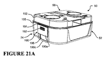
図3に示されるように、加湿チャンバまたはチャンバアセンブリ50は52で概して示される受け皿、すなわち下側部品を含み、これは相補的な大きさと寸法の水槽または容器54を受け、保持するような形状である。上側部品、すなわち蓋56は受け皿52にヒンジ結合され、蓋が水槽54を受け皿52内にしっかりと保持する閉位置(図3に示される)と蓋が受け皿52から離れるように旋回されて、水槽54を例えばクリーニング、補給または交換のために受け皿から取り外すことができる開位置(例えば、図14参照)の間で移動可能である。後で説明するように、蓋は導管および/または流れ面とガイドの構成の形態の整流装置を含んでいてもよく、チャンバ内の入口と出口の間のガスストリームの流路を制御する。
As shown in FIG. 3, the humidification chamber or
この実施形態において、受け皿52と蓋56は射出成形またはその他によって剛性プラスチックから形成されてもよい。一般に、受け皿52、蓋56、およびこれら2つの構成要素間の蝶着手段は1つの部品として相互に一体に形成されるが、他の実施形態においては、蓋と受け皿は別の部分として形成され、その後、1つまたは複数のヒンジによってヒンジ結合されてもよい。蓋および/または受け皿は、設計上の要求事項に応じて、実質的に透明であっても、または不透明として形成されてもよい。水槽またはチャンバベース54は剛性の熱伝導性材料から形成され、一般的には、例えばアルミニウム、ステンレススチールまたはその他の適当な材料等のシート金属からプレス加工または成形されてもよく、または例えばダイキャスティングによって形成できる。
In this embodiment, the
当然のことながら、代替的実施形態において、受け皿52、蓋56、水槽54は他の材料から、または他の方法で形成することもできる。例えば、受け皿52と蓋56は、真空成形によって形成できる。受け皿および/または蓋はまた、金属から、例えばシートメタルからプレス加工され、またはダイキャスティングから形成されてもよい。代替的実施形態においては、水槽はその代わりに、熱伝導性プラスチックから形成することもでもできる。
Of course, in alternative embodiments, the
加湿チャンバの形状
この実施形態において、加湿チャンバ50の全体的な形状は、図4の平面図に示されるように実質的に長方形である。加湿チャンバ50は、第一の端58と第二の端60とそれらの間に延びる第一の側62と第二の側64によって画定される。この説明では、第一の端58を加湿チャンバの後端と考え、第二の端60を前端と考える。第一の側62は、それがブロワからの加圧ガスストリームが加湿チャンバに入る時に通る入口を含むため、加湿チャンバの入口側と考えてもよい。第二の側64は、それが加湿チャンバから出る加湿されたガスストリームのための出口を含むため、加湿チャンバの出口側と考えてもよい。当然のことながら、チャンバの別の説明の中では、内容に応じて、端を側として、またその逆として考えることができる。
Humidification Chamber Shape In this embodiment, the overall shape of the
この実施形態において、端58、60と側62、64を結合する角部は66で概して示されるように湾曲され、または丸みが付けられているが、これは重要ではなく、角部は直角の角部でも、またはその他のどのような輪郭形状であってもよい。この実施形態において、前端60と入口側62を結合する角部66aは残りの角部より大きいが、これは重要ではない。当然のことながら、他の実施形態においては、加湿チャンバアセンブリは、円形またはその他を含むどのような所望の形状または輪郭で形成されてもよく、同じ構築および構成原理が一般的に当てはまる。
In this embodiment, the corners joining the
受け皿
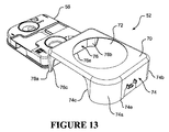
受け皿52は水槽54を受け、保持するように構成され、これは、相補的な形状とわずかにより小さい寸法を有し、それによって受け皿により形成される開放窩洞の中に滑り入れることができる。水槽54と受け皿52の間の適合のきつさは様々であってもよい。いくつかの実施形態では、これは摩擦嵌めでぴったりとしていてもよく、他の実施形態では、これは緩くフィットして、水槽を受け皿に容易にスライド式に出し入れできてもよく、好ましくはその際、使用者が部品の組立または解除のために加える力または圧力が不要か、または最小限となる。チャンバが閉じられていると、受け皿は水槽をしっかりと正確に蓋に当たるように保持するように機能する。特に、受け皿は一般に、水槽をチャンバの開口全体の周囲で蓋に当たるように保持し、蓋と水槽の間の水の飛散を防止/最小化する。受け皿はまた、水槽を所定の位置に保持することと、その一方で蓋をヒンジ結合することの2つの機能を有し、蓋と水槽を位置整合された状態に保ち、これによって使用者はチャンバを閉じる時に蓋と水槽を位置整合させなくてよい。
図13を参照すると、この実施形態において、受け皿52は基底または底面70を含み、その上に水槽54の基底または底面が載る。受け皿52の基底70はまた、中央開口部72を含み、これによって呼吸装置の加温ベースまたは加温パッドが熱伝達のために水槽54の基底の一部と接触し、水槽54内の水の塊を温めるが、これについては後でさらに詳しく説明する。受け皿52は不連続の周壁を有し、これは、この実施形態においては、基底70の周辺から上方に延びる少なくとも1対の対向する壁の形態であって、開放受容窩洞を有する受け皿状の形成部を形成する。この実施形態において、受け皿52は前壁74と後壁76を含み、これらは基底70から上方に延びる。端壁形成部74、76は受け皿のそれぞれ前端と後端の各々に沿って延び、受け皿52の角部周辺の少なくとも一部に沿って延び、各端壁形成部は中央平坦部分を含み、これは中央平坦部分のそれぞれの端の各々において74a、74bおよび76a、76bとして示される湾曲角部へと延びる。
Referring to FIG. 13, in this embodiment, the
この実施形態において、端壁形成部74、76は各々、受け皿の角部領域全体に沿って延び、受け皿のそれぞれの側に沿って終了した後、相互に接合し、それによって受け皿に開放した側壁形成部が提供されて、受け皿52の中に保持された水槽54が露出する。例えば、図6は受け皿52の入口側を示しており、前端壁74と後端壁76が受け皿のそれぞれの角部74a、76aに沿って、および受け皿の側に沿って延び、各々、受け皿の上縁から基底70へと下方に延びる傾斜のついた湾曲縁74c、76cで終了する。当然のことながら、終了する縁74c、76cは必ずしも湾曲した輪郭で斜めに下降する必要はなく、希望に応じて、受け皿の代替的な形態においては、急峻な垂直の縁であってもよい。同様に、図7に示される受け皿の反対の出口側にも同様の構成が提供される。出口側では、端壁74と76もまた、それぞれの角部74b、76bに沿って延び、受け皿の上縁から基底へと下方に延びる傾斜した湾曲縁74d、76dで終了する。
In this embodiment, the end
受け皿52は、少なくとも水槽の対向する端壁と、さらに水槽54の角部分に沿って水槽54を包含する。図6と7に示されるように、この実施形態では、受け皿の周壁は不連続であり、受け皿の壁が水槽54の周壁全体を完全にまたは連続的に包囲せず、または取り囲まず、それによって水槽の壁の一部または複数の部分が露出したままとなる(受け皿により覆われない)。この実施形態において、受け皿の壁は受け皿の各々の側で不連続であり、それによって水槽54の側壁の大部分が露出している(すなわち、受け皿の壁により覆われていない)。例えば、この実施形態において、対向する端壁74、76は受け皿の側の、それぞれの終端の、またはその付近の縁で終了する。当然のことながら、各々の側の端壁74、76が終了する縁間のずれまたは距離は、希望に応じて水槽の側壁の露出する部分を大きく、または少なくするように様々であってもよい。例えば、端壁の何れかまたは両方が、壁の中央に、またはその付近に、またはより壁の角部分の付近で終了してもよい。
The
使用中、受け皿は断熱バリアまたは面を提供し、例えば補給またはクリーニングのためにチャンバを呼吸装置から取り外した後に、使用者は加熱チャンバのそこを掴み、または持ってもよい。これによって使用者は加熱された熱伝導性の水槽に直接触れずに済み、それによってやけどや不快感が回避される。これに加えて、水槽を受け皿から取り外せることにより、両方の部品を十分にクリーニングできる。 In use, the pan provides an insulating barrier or surface, for example, after removing the chamber from the breathing apparatus for refilling or cleaning, the user may grab or hold it in the heating chamber. This saves the user from touching the heated, thermally conductive water tank directly, thereby avoiding burns and discomfort. In addition to this, both parts can be sufficiently cleaned by removing the water tank from the receiving pan.
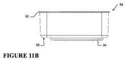
水槽
図11A〜11Cを参照すると、水槽54が単独で示されている。前述のように、水槽54は一般に、シートメタルまたはこれに類するもので形成され、液体、例えば水の塊を保持するための受容部または容器として機能する。図のように、水槽54は受け皿と相補的な形状を有し、それによって水槽54は、たとえは摩擦嵌めによるスライド式係合により、受け皿52の中にぴったりと受けられてもよい。
Water Tank Referring to FIGS. 11A-11C, a
この実施形態において、水槽54は実質的に長方形であり、基底または基底面80を有し、そこから上方に延びる周壁が延びる。特に、水槽54は前端壁82と後端壁84と、端壁間に延びる第一の側壁86と第二の側壁88を含む。端壁と側壁を結合する角壁部分90は好ましくは、図4に関して前述した受け皿の全体的な平面図の形状と相補的な、同様の曲率または半径で湾曲し、または丸みが付けられている。図のように、角部の1つ90aはそれ以外の角部より半径が大きく、受け皿の、より大きい角部66aと相補的である。この構成によって水槽は1つの向きでしか受け皿の中に受けられず、使用者がチャンバと加湿コンパートメントの入口と出口が相互に正しく位置整合されるように部品を組み立てるのを助ける。当然のことながら、水槽、受け皿、蓋は、90°の直角の角部を含めたその他の何れの輪郭の角部を有していてもよく、角部の輪郭は角部ごとに均一でも不均一でもよい。
In this embodiment, the
図11Bを参照すると、周壁の上縁には連続的な、外側に延びるリップ、フランジまたはリム92が設けられる。この実施形態において、リップ92は周壁の上縁において垂直周壁から実質的に水平に、または横方向に外側に延びる。周縁リップ92は任意選択である。設けられた場合、これは受け皿52の端壁74、76の上縁74e、76e(図13と14参照)と係合し、これに当接し、またはその上に載るように構成され、これは例えば図10の断面図において、より見やすい。
Referring to FIG. 11B, the upper edge of the peripheral wall is provided with a continuous, outwardly extending lip, flange or
水槽54には熱伝導接触面または部分94が設けられ、これは基底面80の下面から突出する。接触面94は好ましくは、水槽の残りの部分と一体に形成される。例えば、接触面94は基底面80から押し出されてもよい。この実施形態において、接触面94は円形であり、直径は受け皿52の規定面70に設けられた中央開口部72(図13参照)と実質的に相補的である。特に、水槽54の接触面94は受け皿52の相補的な開口部72と実質的に位置整合され、基底面80の残りの部分に関して、それが開口部72から出て、図6に示されるように受け皿52の規定面70の下面より下に突出するような深さである。加湿チャンバ50が呼吸装置の相補的な加湿コンパートメントの中に挿入されると、水槽54の突出する接触面94はコンパートメント内の加温ベースまたはパッドの上に載り、またはそれと当接し、加温ベースまたはパッドは相補的な大きさと形状であるが、これは重要ではない。すると、加温ベースからの熱が、当然のことながら、熱伝導性(例えば金属)の接触面94を通じて水槽内の水の塊に伝導によって伝えられる。
The
代替的実施形態において、接触面は必ずしも水槽の基底面80の残りの部分より突出している必要はない。例えば、1つの代替的実施形態において、基底面80は平らで、接触面94と同一平面であってもよく、加温ベースまたはパッドは、それが受け皿の開口部72を通って突出して、水槽54の基底面80と係合または接触するような形状であってもよい。別の代替的実施形態において、接触面94は水槽の基底面80の残りの下面に関して窪んでいてもよく、すなわち、それは上方に、水槽の中へと突出する。このような実施形態では、再び、相補的な加温ベースまたはパッドが、受け皿の開口部72を通って突出し、水槽54の基底の窪んだ接触面によって作られる凹部または窩洞に係合できるような高さと形状で構成されてもよい。
In an alternative embodiment, the contact surface need not protrude beyond the rest of the
上記の実施形態において、接触面とこれに関連する構成要素は円形の接触面と加温パッドに関して説明するが、当然のことながら、接触面の他の何れの代替的な形状も利用可能であり、これには正方形、長方形またはその他のあらゆる適当な形状が含まれる。 In the above embodiment, the contact surface and associated components are described with respect to a circular contact surface and a heating pad, but it should be understood that any other alternative shape of the contact surface can be used. This includes squares, rectangles or any other suitable shape.
蓋
図3と4を参照すると、加湿チャンバ50の蓋56は、平面で見た時(図4参照)、受け皿52と水槽54の形状に実質的に対応する。この実施形態において、蓋は主要本体部分100を含み、これは加湿チャンバの上面または上部を形成し、その全体的形状は実質的に長方形であり、受け皿52と水槽54の外形に対応する丸みの付けられた角部を有する。主要部分100から周壁が下方に延びる。例えば、図18において最もよくわかるように、主要部分の各端に前端壁102と後端壁104が設けられている。これに加えて、第一の側壁106と第二の側壁108が主要本体部分100の側に沿って、前および後端壁102、104間に延びる。第一の側壁106は加湿チャンバの入口側にあり、第二の側壁108は加湿チャンバの出口側にある。丸みの付けられた角壁部分110もまた設けられ、これは側壁と端壁を結合して、実質的に水平に延びる主要本体部分100から垂直に下方に延びる周壁全体を形成する。
Lids Referring to FIGS. 3 and 4, the
この実施形態においては、周辺レッジまたはフランジ105(図10と18参照)が蓋の全周に沿って設けられる。レッジ105はこの実施形態において、周壁から外側に実質的に水平方向に延びているが、代替案として、斜めのレッジを使用してもよい。レッジは蓋56の周辺垂直壁の下縁107に向かって、ただしそこからずらして設けられる。使用中、蓋のレッジ105の下面は、水槽54の縁92の上面と当接または係合するように構成される。この実施形態において、蓋56の、レッジ105の下の下側周壁部分91の外面は、図10に示されるように、水槽の、縁92の下の上側周壁部分93の隣接内面から幾分かの隙間を有する(すなわち、少量だけずれている)。これによって蓋は、使用者が大きな力を加えることなく、水槽と係合し、外れる。この実施形態において、蓋の下側周壁部分91は、それが蓋と水槽の間で水が飛散するのを防止するという点で水ガードまたはシールドとして機能し、これに加えて、使用者がチャンバを閉じる際に蓋と水槽の位置整合を助ける。当然のことながら、他の実施形態は、よりきつい摩擦嵌め用に構成してもよく、これによって蓋の下側周壁部分91は水槽の上側周壁部分93と当接または接触する。
In this embodiment, a peripheral ledge or flange 105 (see FIGS. 10 and 18) is provided along the entire circumference of the lid. In this embodiment, the
給水穴
図3と4を参照すると、蓋56には1つまたは複数の給水口または穴が設けられ、そこを通じて、加湿チャンバの水槽54への給水または補給のために水を注ぐことができる。この実施形態において、120で概して示されている2つの同じ給水穴が設けられ、一方は蓋の前端に、またはその付近に、もう一方は蓋の後端に、またはその付近に設けられているが、給水穴の位置はこの構成と異なっていてもよい。この実施形態において、各給水穴はじょうご状の形成部により提供され、これは蓋の主要本体部分100から加湿チャンバの内部へと延びる。例えば、各給水穴120には円錐台形の形成部122が提供され、これは蓋の主要本体部分100と同一平面の第一の端を有し、直径が徐々に減少しながら加湿チャンバの中へと下方に延び、この場合は円形である給水口の縁124に対応する第二の端で終了する。当然のことながら、給水穴のじょうご状の形成部は任意選択であるが、チャンバへの給水中に飛散したり、こぼれたりするのを減少させるのに役立つ。代替的実施形態において、給水穴は単純に、主要本体部分の中に形成された、円形またはその他の開口部で、このような案内用のじょうご状の形成部を全く持たなくてもよい。
Water Holes Referring to FIGS. 3 and 4, the
この実施形態において、各給水穴120には1つまたは複数の同心の円形の隆起した密閉リブ121または給水穴の周辺に沿って延びる突出部が設けられる。これらの密閉リブ121は蓋と一体に形成されても、蓋に取り付けられてもよい。密閉リブ121は、剛性または硬質プラスチックで形成されてもよく、それによって柔らかいシール材がリブと密閉状態で係合して、給水穴を閉じることができる。例えば、柔らかいシール材は、使用中にチャンバがその中に配置される加湿コンパートメントの蓋に設けられてもよい。代替的実施形態において、リブ121は柔らかいオーバーモールド成形されたプラスチックまたはゴムまたはシリコンであってもよく、加湿コンパートメントの蓋に設けられた硬い面または形成部と密閉状態で係合し、呼吸装置内で使用される時に給水穴を閉じる。
In this embodiment, each
水位表示器
図18を参照すると、加湿チャンバ50は少なくとも1つの水位表示器を含み、これは、少なくとも水位が最高水位に近付いていることを示す表示を使用者に提供するように構成される。この実施形態において、水位表示器130は各給水口120のために設けられ、タブ型水位表示器130の形態であり、これは蓋から支持され、加湿チャンバの内部空間内へと下方に、特に水槽54によって画定される領域の中へと延びるタブまたは部材を含む。この実施形態において、各水位表示器130は実質的に垂直に延びる支持部材132を含み、これは給水用開口部の縁124の下面から下方に延び、内側に延びるタブ部分または部材134で終了し、これはその給水用開口部に関連する、実質的に垂直な注水経路領域または視野内へと延びる。特に、タブ部分134は、使用者が上から給水用開口部の中央を直接見た時に実質的に見え、すなわち、給水用開口部から見たチャンバ内部の視野の中に配置される。この実施形態において、垂直支持部材132とタブ部分134の間の角度は鈍角であり、タブ部分134は垂直に延びる支持部材132から下向きの勾配で延びる。図4と18に示されているように、各タブ部分130には最高水位表示形成部138が設けられる。この実施形態において最高水位表示形成部138は、タブ部分134の何れかの側から外側に延びる三角形の形成部として提供されているが、当然のことながら、他のあらゆる形態の表示器も利用でき、これには印刷された表示手段、マークまたは指標、例えば印刷された線またはその他が含まれる。タブ部分134は水平に関して下降勾配または傾斜を有するため、使用者には、水槽に給水している時および水位がタブ部分134と接触して上昇を始めた時に、最高水位に近付いているとの警告が提供される。しかしながら、当然のことながら、代替的実施形態においては、タブ部分134は実質的に水平であってもよく、それによってタブ部分134と垂直支持部材132の間が90°、すなわち直角となり、このような実施形態において、使用者には水がタブと接触した直後に水槽への最高水位までの給水が警告される。当然のことながら、タブ部分134の下降勾配または傾斜が大きいほど、使用者には、タブ上の水位が最高水位表示形成部138に次第に近づくのが見えるため、最高水位給水量に近付いているとの警告がより多く提供される。
Water Level Indicator Referring to FIG. 18, the
別の説明として、給水用開口部120に関連する視野区域は、使用者が給水用開口部の中央のまっすぐ上にいる時に見えるチャンバ内部の可視領域である。例えば、図20を参照すると、視野区域は、給水用開口部120の縁124から下方に延びる仮想の円筒形ゾーンと考えることができ、これは加湿チャンバの図20の断面図の矢印BB間に示されている。図のように、最高水位表示形成部138を含むタブ部分134は、給水用開口部120の視野区域の中へと延びるように構成される。これは、水位表示器が給水用開口部を通じて直接見ることができ、使用者にとって、同じ穴から給水中に同時に見えることを意味する。
As another explanation, the viewing area associated with the
蓋の入口
蓋56にはガス入口が設けられ、そこを通って、呼吸装置のブロワにより生成された加圧ガスストリームが加湿チャンバ50の内部へと流入する。図3〜6を参照すると、ガス入口140は加湿チャンバ50の入口側62に設けられている。図6に示されるように、ガス入口140は、この場合は長方形であるが円形またはそれ以外のあらゆる他の形状であってもよい開口部の形態で、蓋56の入口側周壁106に設けられる。この実施形態において、ガス入口140は周壁106に沿って中央に設けられているが、この位置は様々であってもよい。図18を参照すると、この実施形態において、入口開口部140にはこれに関連する入口通路または導管142が設けられ、これは入口のガスの流れのストリームを蓋の中央区域または領域へと誘導し、または方向付け、その後、導管142を出て加湿チャンバの内部へと出るようにする。この実施形態において、入口導管142は、壁106の入口開口部にある第一の端142aと蓋の中央区域の付近にある第二の端142bの間に延びる。中空の入口導管142は、入口開口部140の形状に対応する断面形状を有し、蓋52の垂直周壁106から実質的に水平方向に内側に延びる。入口導管142は蓋の中央区域へと延びて、呼吸装置がその通常の直立した動作時の向きから偶然傾き、または転倒した場合のブロワまたは装置への水の逆流を最小化または減少させるのを助ける。
この実施形態において、ガス入口140と入口導管142は、蓋の上部に、またはその付近に配置されている。しかしながら、代替的実施形態においては、蓋はより高い周壁を有し、より深くてもよく、入口140と導管142は蓋の上部から離れた位置にずらしても、例えば蓋の底部に、またはその付近に配置されてもよい。このような構成によって、蓋の入口より上に、チャンバが傾いている時に水がたまるための空間ができ、入口から水が逆流する可能性を低減させうる。
In this embodiment, the
入口導管142の出口において、入口導管から出るガスストリームを方向付けるための流れ誘導形成部144が設けられる。この実施形態において、流れ誘導形成部144は湾曲した下向きの傾斜面の形態であり、これは入口導管142の出口端142bにおいて蓋の主要本体部分100で、またはその付近で始まり、蓋の主要本体部分100から下方に延びる垂直流れパネル146の第一の面146bで終了する。この構成により、入ってくるガスストリームの一部が加湿チャンバの入口壁に向かって戻り、そこで加湿されてから再び流れパネル146の側端146eを通過して加湿チャンバの出口に向かって循環する。この構成はまた、空気の流れを水の表面へと直接方向付けて、水から流入ガスへの水分の吸収を増大させるのを助ける。垂直流れ面146は、入口導管142の出口端142bからずれている。
A
図20は、垂直流れパネル146の第一の面146bを示す。この実施形態において、垂直流れパネル146、すなわち整流装置の幅(W)は、加湿チャンバの、前端60から後端58までの全長より短いが、好ましくは、入口導管142の幅(W1)より広い。この実施形態において、垂直流れパネルの高さ(H)は、その下端146aが少なくとも入口導管142の下端142aより下まで延び、一般に少なくとも、タブ型水位表示器の表示形成部138により示される水平な最高水位線より下までさらに延びる、というものである。この実施形態において、垂直流れ面146の下端146aは、最高水位表示形成部138と水槽54の下側基底面80の間に位置付けられるが、代替的実施形態においては、実質的に水槽54の基底面80まで延びていてもよい。好ましくは、垂直流れパネル146の高さは、その下端146aが、少なくとも最高水位線に到達している量の水については、水槽54の水の表面の中まで、またはそれを通って延びる、というものであり、より好ましくは、下端146aが少なくとも最高水位線に到達していない量の水について、およびさらにより好ましくはあらゆる量の水について、水の表面の中まで延びるように構成される(すなわち、下端146aは実質的に水槽の基底面まで延びる)。一般に、流れパネルの高さは、それが水の表面の中に、入口導管142を出たガスが下端146aの下を通過して、出口導管142へと直接通過するのを防止するのに十分な深さだけ突出または貫通するように構成され、それによってガスは強制的に流れパネルの周囲に流れ、ガスがチャンバ内で、チャンバを出る前に水蒸気に曝されながら通過する経路が増大する。流れパネルの高さが低すぎて、ガスが流れパネルの下から直接出口へと流れることができた場合、その結果として流路が短縮され、加湿が低下し、また、ガスストリームが流れパネルの下から戻る時に、ガスストリームが出口導管152の中に水を吹き込み、または飛び散らせることにもなりうる。
FIG. 20 shows the
蓋の出口
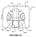
図4と7を参照すると、ガス出口150が加湿チャンバのガス入口140とは反対側に設けられている。この実施形態において、ガス出口150は、加湿チャンバの蓋56の出口側周壁108に設けられ、ガス入口140と同様に、加湿チャンバの前端と後端に関して中央に配置されているが、これは重要ではない。ガス出口150は実質的に長方形の、周壁108を通って延びる開口部を含むが、その代わりに円形またはそれ以外の他の形状の開口部も利用できる。加湿チャンバ内でガスが加温加湿されると、ガスストリームはガス出口150を通って加湿チャンバから出る。
4 and 7, a
図12と19を参照すると、この実施形態では、ガス出口150が出口導管152を含み、これは加湿チャンバの蓋の中央区域または領域へと、周壁108に関して水平または垂直方向に延びる。特に、出口導管152は、壁108の中のガス出口150の開口部にある第一の端152aから延び、蓋56の内部へと延び、第二の端152bで終了する。この実施形態において、出口導管152の第二の端152bは垂直流れパネル146の第二の面146cと当接または係合している。出口導管152の第二の端152bには、またはその付近には、1つまたは複数の入口開口部が設けられ、加湿チャンバ内のガスはそこを通って導管152に入ってもよく、ガス出口150を通って加湿チャンバを出てもよい。この実施形態では、出口導管152は実質的に長方形であり、その長さに沿って延びる下側壁152cと上側壁152dおよび左側壁152eと右側壁152fを有する。この実施形態において、2つの主要入口開口部154aと154bは入口導管の第二の端152bに、またはその付近において、側壁152eと152fの各々に設けられ、それによって入口は蓋の前端または後端の何れかに向かって開放する。この実施形態において、入口開口部154a、154bは実質的に長方形であるが、円形またはそれ以外であってもよい。図7、12、19に示されているように、垂直壁形成部155a、155bは、それぞれの入口開口部154a、154bの各々の領域内で導管の下側壁152cから上方に延びる。壁形成部155a、155bは、水の飛散バリアとして機能し、ガスストリームを、開口部のすぐ下の水の表面から直接開口部に移動するのではなく、開口部154a、154bに入る前に壁の周囲で上昇させるように構成される。この構成によって、水がガスストリームに捕捉され、または運ばれ(特に流速が速い場合)、出口導管152に入る可能性が低下する。当然のことながら、入口導管152は必ずしも垂直流れパネル146と接触するまで延びている必要はなく、その代わりに、垂直流れパネル146と蓋の側壁108の間のある位置で終了してもよい。
Referring to FIGS. 12 and 19, in this embodiment, the
蓋の入口と出口の接続
前述のように、ガス入口140とガス出口150は、加湿を最大限にするために加湿チャンバ内に所望のガス流路を構築するための、関係する導管142と152を有するが、当然のことながら、これらの導管は重要ではない。代替的実施形態においては、ガス入口140とガス出口150は単純に、側壁の開口部であって、加湿チャンバの内部へと延びる導管がなくてもよい。
Lid Inlet and Outlet Connections As noted above, the
入口および出口導管142、152が設けられている場合、当然のことながら、これらは必ずしもそれぞれ反対側から中央に、それぞれの周壁に対して垂直にチャンバの蓋に入る必要はない。導管は蓋の角部に配置されてもよく、どのような所望の角度でチャンバ内に入ってもよい。これに加えて、導管は必ずしもまっすぐな導管である必要はなく、まっすぐ以外でもよく、1つまたは複数の屈曲または曲りを含んでいてもよい。
If inlet and
当然のことながら、加湿チャンバのガス入口140とガス出口150は、呼吸装置のガス流路へと様々な方法で接続されてもよい。当然のことながら、ガス入口140はガス流路に、ブロワを出るガス流路に連結された1つまたは複数の導管、コネクタ、および/またはガスケットによって、密閉された、または密閉されていない構成で連結または流体接続されてもよい。同様に、ガス出口150はどのような適当な方法で連結されてもよく、例えば、コネクタ、導管および/またはガスケットを含むどのような適当な方法でも、密閉された、または密閉されていない構成で、呼吸装置のガス出口につながるガス流路に連結されてもよく、このガス出口が今度は、前述のように、患者用インタフェース、例えば柔軟なガス送達導管および使用者用インタフェースに接続される。
Of course, the
この実施形態において、図2に関して上述したように、チャンバはブロワ出口に流体接続されたガス入口と、一般的に患者用インタフェースに連結された、またはそれに接続可能な呼吸装置の主要ガス出口に流体接続されたガス出口を含む密閉可能な加湿コンパートメントの中に保持される。この実施形態において、チャンバのガス入口140はコンパートメントの入口に密閉状態で接続されるのではなく、密閉されたコンパートメントに入る加圧ガスに対して開放している。その代わりに、チャンバの入口とコンパートメントの間には密閉された接続を利用してもよい。この実施形態では、チャンバのガス出口150は好ましくは、ガスケットまたはその他の密閉された接続構成を介して、加湿コンパートメントのガス出口に密閉状態で接続または連結されるか、または少なくとも相互に密接して位置整合されて、チャンバを迂回して直接コンパートメントの出口に向かうガスを最少化する。
In this embodiment, as described above with respect to FIG. 2, the chamber is fluidly connected to the gas inlet fluidly connected to the blower outlet and to the main gas outlet of the breathing apparatus generally connected to or connectable to the patient interface. Retained in a sealable humidified compartment containing a connected gas outlet. In this embodiment, the
ヒンジとクリップ
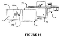
前述のように、蓋56は受け皿52にヒンジで連結または接続され、これらは蓋が受け皿から離れるように旋回して、水槽54を受け皿から外すことのできる(または、蓋を開けて水槽に給水し、またはこれをクリーニングすることのできる)開位置と、蓋が旋回されて受け皿と係合し、水槽が蓋と受け皿の間に囲い込まれ、固定される閉位置の間で移動可能である。この実施形態において、蓋56はチャンバの後端にあるヒンジの周囲で、閉位置、すなわち図3に示される状態と開位置、すなわち例えば図13〜16に示される状態の間で旋回する。
Hinges and Clips As previously mentioned, the
この実施形態において、1つまたは複数のヒンジが加湿チャンバの後端に配置され、これらは蓋56を受け皿52にヒンジ結合するように構成されている。図8、15、16を参照すると、この実施形態では、1つの長いリビングヒンジ160が加湿チャンバの後端の、蓋56と受け皿54の間の一部に沿って延びている。特に、リビングヒンジ160は薄い柔軟なプラスチックヒンジであり、受け皿の後壁76の上縁76eの一部と蓋56の後端のレッジ105の一部と一体に形成され、その間に連結される。しかしながら、当然のことながら、2つまたはそれ以上のヒンジを加湿チャンバの後端に沿って、蓋と受け皿の間に設けてもよく、ヒンジは必ずしも一体形成されたリビングヒンジである必要はなく、別々に形成され、蓋と受け皿に固定されるヒンジまたは蝶着機構であってもよい。
In this embodiment, one or more hinges are located at the rear end of the humidification chamber and are configured to hingedly join the
加湿チャンバを閉状態に固定するために、1つまたは複数の操作可能クリップまたはクリップ機構が提供され、加湿チャンバを閉位置に固定するためのラッチまたはロック位置と、蓋が受け皿から旋回して開位置または構成へと旋回できるラッチ解除またはロック解除位置との間で操作可能である。 To secure the humidification chamber in the closed state, one or more operable clips or clip mechanisms are provided, the latch or lock position for securing the humidification chamber in the closed position, and the lid pivoting open from the pan. It is operable between an unlatched or unlocked position that can pivot to a position or configuration.
図9と17を参照すると、この実施形態において、1つの操作可能クリップ170が蓋56に提供または固定されており、これは受け皿52に設けられた相補的な留め具172との係合位置と非係合位置との間で弾性的に移動可能である。特に、クリップ170は蓋56の前壁102の中央位置に設けられる。図17を参照すると、この実施形態において、操作可能クリップ170はトーションクリップの形態であり、受け皿52に設けられた相補的な留め具172に関して係合および非係合位置間で移動可能である。クリップ170は、使用者がクリップを非係合位置にするように移動または旋回させる時に押すことのできる使用者接触部分174と、係合開口部176aを含む係合タブ部分176を含む。使用中、留め具172は、受け皿の前壁74から突出する突起または係合形成部であり、クリップと位置整合して、クリップがラッチまたはロック位置にある時にクリップ170の係合開口部176aと係合し、それによって蓋56を受け皿52に固定する。
Referring to FIGS. 9 and 17, in this embodiment, one
図のように、クリップ170は蓋56にねじれ部材178a、178bを介して取り付けられ、これらはクリップの各々の側から、係合タブ部分176の端と使用者接触部分174の間に延びる。ねじれ部材178a、178bは長手方向に位置整合し、旋回軸DDを画定し、その周囲でクリップ170が蓋56に関して、図のような休止(係合、ラッチ)位置と、蓋を受け皿から釈放できるラッチ解除または係合解除位置の間で旋回または回転できる。図のように、使用者接触部分174は蓋の前壁102の付近に配置され、その一方で係合タブ部分176はレッジ105と蓋56の下端の下に下方に延びる。ねじれ部材178a、178bの各々は、前壁102に設けられたそれぞれの支持用支柱180a、180bとクリップ170の側面の間に延びる。この実施形態において、ねじれ部材178a、178bは実質的に円筒形であり(ただし、正方形、長方形またはそれ以外のように、その長さに沿った断面形状は異なっていてもよい)、その長手方向軸の周囲で小さな角度でよじれ、または曲り、それによってクリップが旋回軸DDの周囲で旋回または回転できるようにする。図のように、クリップ170はねじれ部材178a、178bによってその休止位置に、またはそれに向かって付勢される。
As shown, the
使用中、蓋56が開位置から閉位置に移動されると、係合タブ176の先端が留め具172のカム面172a(図14参照)と係合し、それによってクリップが蓋の前壁102から外側に、図17に示される方向Fへと旋回する。蓋56が受け皿52と完全に係合すると、留め具172は係合タブ部分176の係合開口部176aとスナップ式に完全に係合し、それによってクリップがその休止位置へと戻って、ばね状に返り、蓋を受け皿にしっかりと引っ掛け、この時、使用者はクリップを操作してそれを開口部と係合させる必要がない。クリップ機構を解除して、加熱チャンバを開けことができるようにするには、使用者は単純に使用者接触部分174を押して、それを図のように方向Eへと蓋の前壁102に向かって移動させる。これによって係合タブが再び旋回軸DDの周囲で前壁から遠ざかるように方向Fへと回転し、係合開口部176aが相補的な留め具172から外れ、それによって蓋56は受け皿52から完全に旋回して開いた状態となる。使用者が使用者接触部分174に加えている圧力を解除すると、クリップは、加湿チャンバが閉じられた時に、再びラッチ状態にできる休止位置へと戻る。
In use, when the
図17に示されるように、蓋の前壁102には、チャンバの前壁の、使用者接触部分174の背後に2つの限界突起182が設けられ、これらは使用者がクリップを回しすぎないように、または捻りすぎないようにし、クリップ機構の破損を防止する役割を果たす。図14を参照すると、ガイド形成部184が任意選択によって留め具172のそれぞれの側に設けられ、これらは受け皿52の前壁74から突出する。使用中、ガイド形成部184は、係合位置にある時、クリップの係合タブ部分176がガイド形成部184間に適合できるのに十分な距離だけ離して設置される。
As shown in FIG. 17, the
図の実施形態においては、クリップ170が蓋に、留め具172が受け皿に取り付けられているが、当然のことながら、希望に応じてこれを逆転させて、クリップを受け皿に、留め具を蓋に固定してもよい。
In the illustrated embodiment, the
当然のことながら、加湿チャンバの蓋56を受け皿52に固定するために、他の様々な代替的なクリップ構成または機構を利用してもよい。2つまたはそれ以上の操作可能クリップまたはラッチを、必要に応じて、加熱チャンバの周辺に沿って1つまたは複数の壁に設けてもよい。各種のクリップ機構のその他の例を、加熱チャンバの代替的な実施形態に関して以下に説明するが、当然のことながら、かかるクリップ機構は加湿チャンバのこの第一の実施形態にも利用できる。
It will be appreciated that various other alternative clip configurations or mechanisms may be utilized to secure the
シーリング
図10を参照すると、この実施形態においては、加湿チャンバの周辺の蓋56と水槽54の間には柔軟なシール材(例えば、シリコンまたはゴム、またはそれ以外)が設けられていない。加湿チャンバが閉じられた時にクリップ機構により生成される圧力は、蓋56と水槽54の間の接合面におけるガスおよび/または水の漏出を減少させ、または最少化にするのに十分であると考えられる。また、呼吸装置の加湿コンパートメント内に配置された時に、追加の下方の圧力が蓋54に加わるかもしれない。例えば、加湿コンパートメントの蓋は、加湿チャンバの蓋56を押し下げ、またはこれと係合し、それによって蓋56に下方の力をかけて、よりしっかりと閉じた状態にするように構成されてもよい。チャンバは加圧された加湿コンパートメント内に配置されるため、チャンバの外と中との圧力差は無視できるか、ゼロに近い。このような実質的な中立圧力差によって、空気の流れが蓋と水槽の間の接合面または周辺境界を介してチャンバ内に出入りする傾向が減少し、したがって、一般的にシール材が不要となる。
Sealing Referring to FIG. 10, in this embodiment, no flexible sealing material (eg, silicon or rubber, or otherwise) is provided between the
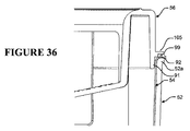
しかしながら、当然のことながら、代替的実施形態においては、1つまたは複数の柔軟なシール材を加湿チャンバ周辺に沿って蓋56と水槽54の間に設置することにより、水槽と蓋の間の接合面において加湿チャンバからガスおよび/または水が漏れる可能性をさらに最小化してもよい。例えば、周辺柔軟シール材は、水槽54の縁92または蓋56の下端107またはレッジ105の何れか、または両方にも取り付けてよい。図36を参照すると、1つの考えうる密閉チャンバ構成が示されており、周辺凹部または溝が蓋のレッジ105の下面に、チャンバ周辺全体に沿って設けられ、シール材、例えばシリコンまたはゴムのOリングまたはこれに類するものが溝の中に取り付けられ、または配置されて、チャンバが閉じられた時に水槽の縁92と密閉状態で係合する。
However, it will be appreciated that in an alternative embodiment, one or more flexible seals are placed between the
代替的なクリップ機構
前述のように、加湿チャンバ50の蓋56を受け皿52に固定するために、各種の代替的なクリップ機構を使用してもよい。ここで、いくつかの代替的な種類のクリップ機構を単に例として説明するが、当然のことながら、これらの例は限定的とは意図されない。
Alternative Clip Mechanisms As described above, various alternative clip mechanisms may be used to secure the
第一の代替的クリップ機構
図21A〜21Cを参照すると、第一の代替的クリップ機構は、191で示されるリビングヒンジを介して蓋56の前端壁に回転可能に連結されたクリップ190を含む。図のように、クリップ190は蓋56のレッジ105にヒンジ結合される。この実施形態において、クリップ190は主要平坦タブ部分190aを含み、これは受け皿52の前壁に設けられた相補的な形状の留め具または突出形成部192と係合するように構成された中央係合開口部190bを含む。クリップ190は下方に延びるつまみまたは把持部190cをさらに含む。この実施形態において、指用つまみ190cは薄いプラスチックの柔軟なU字形部材の形態であり、これは主要タブ部分190aの下端から延びる。特に、つまみは主要タブ部分190aの下端の両側から下方に延びる第一と第二の脚部193を含み、これらは横木部材194により結合され、把持用開口部198を提供する。指用つまみ部分190cはクリップの主要タブ部分190aと1つの部品として一体に形成されるか、あるいは別々に形成して、クリップに取り付けられ、または固定されてもよい。
First Alternative Clip Mechanism Referring to FIGS. 21A-21C, the first alternative clip mechanism includes a
図のように、指用つまみ部分は好ましくは、それに対応する主要タブ部分190aより薄く、曲げることができ、または柔軟である。この実施形態において、指用つまみ部分190cは、実質的に受け皿52の底面に向かって、またはそこまで延び、使用者が指を掛け、または把持しやすくなる。この構成によればまた、使用者は、自分の指のより多くの部分、及び/または複数の指を把持用開口部198に入れることによって、指先で起こして負荷のほとんどを、第一関節を通じて加えるのではなく、腕の力を使ってクリップを引くことができる。これに加えて、図21Cに示されるように、受け皿52の前壁には凹部195が設けられてもよく、これはつまみ190cと位置整合し、それによって使用者の指がつまみ190cに届き、これを把持することができる。この実施形態において、留め具形成部192は、三角形の断面を有する長い形成部を含む。特に、正面の、下方に角度の付いた前側カム面192aが受け皿の前壁74から延び、実質的に水平な係合面192bが形成部の下面に設けられる。係合面192bの前端にはまた隆条部または突出リップが設けられ、これは下方に延びて、クリップを留め具形成部192と係合状態に保持するのを助ける。
As shown, the finger grip portion is preferably thinner, bendable or flexible than the corresponding
使用中、使用者はクリップ190をそのリビングヒンジの周囲で押し、または旋回させて留め具形成部192と係合させ、図21Aに示されるラッチ位置にする。クリップ機構を解除するには、使用者は1本または複数の指を使ってクリップのつまみ部分190c(または使用者の好みに応じて主要タブ部190aそのもの)に、受け皿の前壁から遠ざかる方向の力を加え、クリップを係合形成部192から外し、それによってクリップおよびそれによって蓋56を受け皿52から外す。
In use, the user pushes or pivots clip 190 around its living hinge to engage
第二の代替的クリップ機構
図22Aを参照すると、第二の代替的クリップ200が示されている。クリップ200は主要タブ部分201を含み、これは、第一の代替的クリップ190と同様に、リビングヒンジ202を介して蓋56の前壁102のレッジ105に一体に連結される。前述のように、リビングヒンジ202はプラスチックの厚さを薄くした部分から形成され、柔軟であり、それによってクリップ200を蓋56に関して旋回できる。第一の代替的クリップ190の係合用開口部190bと異なり、第二の代替的クリップ200には突出する係合形成部203が設けられ、これは受け皿の前壁に設けられた相補的な留め具形成部または開口部(図示せず)と係合するように構成される。
Second Alternative Clip Mechanism Referring to FIG. 22A, a second
第三の代替的クリップ機構
図22Bを参照すると、第三の代替的な種類のクリップ機構が示されている。第三の代替的な種類のクリップ210は第一の代替的クリップ190と同様であり、ヒンジ結合されたタブ211を含み、これは受け皿の前壁に設けられた留め具形成部212と係合するように構成された係合用開口部を有する。この実施形態では、タブ211に延長つまみは設けられていない。
Third Alternative Clip Mechanism Referring to FIG. 22B, a third alternative type of clip mechanism is shown. A third alternative type of
第四の代替的クリップ機構
図23Aと23Bを参照すると、第四の代替的な種類のクリップ機構が示されている。第四の代替的な種類のクリップ290は第一の代替的クリップ190と同様であり、同様の参照番号は同様の特徴を示す。クリップ290は延長つまみを持たないヒンジ結合されたタブを含む。むしろ、タブは、蓋にヒンジ結合された垂直方向の第一の上側部分291と、上側部分から斜めに離れるように延びる、より大きい下側傾斜部分292を有する。上側部分291は、前述のように、受け皿の前壁の留め具形成部192と係合するための係合用開口部を提供する。図の係合位置においては、タブの下側傾斜部分292は外側に、すなわち受け皿52の壁から離れるように傾斜し、それによって下側傾斜部分292と前壁の凹部195の間に把持用の凹部またはアクセス空洞が形成され、使用者は希望に応じてタブを掴み、引いて、クリップを外すことができる。
Fourth Alternative Clip Mechanism Referring to FIGS. 23A and 23B, a fourth alternative type of clip mechanism is shown. The fourth alternative type of
代替的な水位表示器
当然のことながら、使用者が、水槽に最高水位線まで給水したことを識別するのを助けるために、他の様々な水位表示器を使用でき、そのいくつかの非限定的な例をここで例として説明する。
Alternative water level indicators Naturally, various other water level indicators can be used, some of which are non-limiting, to help the user identify that the tank has been filled up to the maximum water level. A specific example will now be described by way of example.
第一の代替的水位表示器
図24Aと24Bを参照すると、第一の代替的水位表示器220が示されており、これは前述のタブ型水位表示器130の変化形である。同様の参照番号は類似の構成要素と特徴を示す。この変化形においては、追加の垂直支柱または部材221が蓋56の下面から下方に延び、タブ134の終端と結合して、水位表示器を補強し、タブの角度を保持する。
First Alternative Water Level Indicator Referring to FIGS. 24A and 24B, a first alternative
第二の代替的水位表示器
図25と26を参照すると、第二の代替案の水位表示器230が示されている。水位表示器230は円錐形水位表示器であり、中空の円筒形形成部231を含み、これは蓋の上側主要部分から下方に延び、233で概して示されるような少なくとも最高水位線を示す表示手段又は標識を含む円錐端部232で終了する。水位表示器は、透明プラスチック等の透明材料から形成される。円錐部分232の急峻さは、それらが最高水位線に接近する時に使用者が得る警告の量を変えるために様々であってもよい。角度が急峻であるほど、より少ない警告が提供される、より浅い円錐より多くの警告が提供される。この実施形態において、蓋56には234で概して示される1つの給水用開口部が設けられている。
Second Alternative Water Level Indicator Referring to FIGS. 25 and 26, a second alternative
第三の代替的水位表示器
これに加えて、またはその代わりに、他の実施形態において、水位表示線(複数の場合もある)は水槽の周壁の内面に、例えば線を表面に印刷することによって、またはそれ以外に水槽の壁内面に線をプレス加工または形成することによって設けられてもよい。このような水位表示線は、蓋が開いている時に見え、それによって水を水槽の最高水位線まで水槽内に直接注ぐことができる。このような実施形態において、蓋の別の給水穴を省くことができる。
Third alternative water level indicator In addition or alternatively, in other embodiments, the water level indicator line (s) may be printed on the inner surface of the peripheral wall of the aquarium, eg on the surface. Or otherwise may be provided by pressing or forming lines on the inner surface of the aquarium wall. Such a water level indicator line is visible when the lid is open, so that water can be poured directly into the aquarium up to the maximum water level line of the aquarium. In such an embodiment, another water supply hole in the lid can be omitted.
ここで、各種の他の加湿チャンバの実施形態を説明するが、同様の参照番号は同じ、または同等の構成要素または特徴を示す。当然のことながら、各種の実施形態の特徴と構成要素を置き換え、および/または組み合わせて、別の変化形の実施形態を創出してもよい。 Various other humidification chamber embodiments will now be described, where like reference numbers indicate the same or equivalent components or features. Of course, the features and components of the various embodiments may be replaced and / or combined to create other variations of the embodiments.
第二の実施形態の加湿チャンバ−連続型受け皿を使用
図27A〜27Cを参照して、第二の実施形態の加湿チャンバ300を説明する。加湿チャンバ300は第一の実施形態と実質的に同様である。図のように、蓋56は第一の実施形態と実質的に同様であるが、これは前壁に異なるクリップ機構310を含む。この実施形態において、クリップ310はU字形部材であり、これは前壁に取り付けられ、図27BのIIで示される軸の周囲である程度曲がる。図27Aに示されように、クリップ310は留め具形成部312としっかりと係合する。図27Cを参照すると、留め具形成部は、実質的に三角形の断面を有する長い形成部を含む。特に、傾斜した前側カム面314が前壁から下方および外側に延び、実質的に水平の係合面316が前側カム面314の下端から前壁に戻る。U字形クリップ310は2つの垂直脚部318を含み、これらは蓋から下方に延びて、横木部材320によって結合される。使用中、横木部材320は、蓋が受け皿352と係合すると留め具形成部312のカム面314と係合し、最終的に係合面316と完全に係合するようにスナップ式に嵌り、またはロックされる。
Humidification chamber of the second embodiment-using a continuous tray The
他の態様に関して、第二の実施形態の加湿チャンバ300は第一の実施形態と実質的に同様であり、前述の種類の金属製水槽を受けるプラスチックの受け皿352とヒンジ結合されたプラスチックの蓋56を含む。第二の実施形態の加湿チャンバ300の主な違いは、受け皿が水槽の周壁の周囲で実質的に連続しており、それが水槽周壁面の全体を実質的に包含し、取り囲むようになっている点である。
In other respects, the
第三の実施形態の加湿チャンバ−オーバーモールドによる加温板を使用
概要
図28A〜28Tを参照しながら、第三の実施形態の加湿チャンバ400についてより詳しく説明する。加湿チャンバ400は全体的形状において前述の実施形態と同様であり、適用可能な同様の特徴は同様の図面参照番号で表される。当然のことながら、同様の特徴に関する上述の実施形態の説明は、変化形や代替案を含め、この実施形態にも当てはまるため、繰り返さない。以下の説明は、第三の実施形態の前述の実施形態との違いに焦点を当てる。
Overview of Use of Heating Plate by Humidification Chamber-Overmold of Third Embodiment The
第三の実施形態の加湿チャンバ400の主な違いは、これが2部式のチャンバアセンブリであり、前述の実施形態のように3部式のチャンバアセンブリではない点である。「2部式」および「3部式」アセンブリという語句は、アセンブリの主要構成部品の数を指すものであり、これらが一体に形成されているか、またはそれ以外に相互に接続、連結または組み立てられているかを問わない。特に、前述の実施形態は、3部式チャンバアセンブリに関し、これは、上側部品(蓋−部品1)を含み、それが下側部品(受け皿−部品2)に関して開閉するようにヒンジ結合され、部品2は別の水槽(部品3)を釈放可能に受け、保持する。これに対して、この第三の実施形態の加湿チャンバ400は2部式アセンブリであり、蓋456(部品1)の形態の上側部品を含み、これは一方の側において、その基底面に熱伝導性の金属加温板を含む水槽452(部品2)の形態の下側部品にヒンジ結合される。
The main difference of the
この実施形態において、蓋456と水槽452(金属製の加温板を除く)は、前述の実施形態の蓋と受け皿の形成と同様の方法で、剛性プラスチックから射出成形、真空成形または、他の適当な生産工程によって形成される。一般に、蓋456、水槽452、および蓋と水槽の間の蝶着部160は1つの部品として相互に一体に形成されるが、代替的な実施形態においては、蓋と水槽は別の部品として形成されて、その後1つまたは複数の別々の蝶着構成要素またはアセンブリを介してヒンジ結合されてもよい。水槽および/または蓋は、設計上の要求事項に応じて、実質的に透明であっても、または不透明に形成されてもよい。
In this embodiment, the
前述の実施形態と同様に、加湿チャンバ400は、蓋456が水槽452に固定されて、閉じたチャンバを作る閉位置(例えば、図28Aと28Bに示される)と、蓋456がヒンジ160の周囲で水槽から遠ざかるように移動または回転されて、アクセスのためにチャンバを開く、図28Lから28Nに示されるような開位置または状態の間で操作可能または移動可能である。1つまたは複数の操作可能クリップ290またはラッチが加湿チャンバの前端に設けられ、前述のように、加湿チャンバを呼吸装置内に挿入し、動作できる状態の閉位置に固定またはロックする。
Similar to the previous embodiment, the
水槽
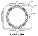
図28A、28B、28L、28Mを参照すると、水槽452は基底面470を含み、そこから基底面の周囲に沿って直立の側壁が延びる。図のように、水槽はそれぞれ加湿チャンバの前端と後端の前壁474と後壁476と、それぞれ加湿チャンバのガス入口側とガス出口側に沿って延びる第一の側壁475と第二の側壁477を含む。
Water Tank Referring to FIGS. 28A, 28B, 28L, 28M,
図28D、28E、28Fを参照すると、壁の1つまたは複数または壁の一部には、壁面の曲りまた変形に抵抗するように構成された補強形状が設けられていてもよい。この実施形態において、側壁475、477の各々には、それぞれ補強部分または領域478、479が設けられ、これらは溝と畝が交互にある波形または起伏のある表面形状を含む。この実施形態において、溝と畝は垂直の向きを有するが、当然のことながら、代替案においては希望に応じて水平方向も利用できる。この実施形態において、補強、すなわち波形部分の側壁の厚さは実質的に均一であり、畝と溝および畝と溝の間の遷移区間は、図28Dからわかるように、実質的に同様の壁圧である。代替的実施形態において、補強領域の側壁の厚さは不均一であってもよい。この実施形態において、波形領域の各々の高さは、図28Eと28Fに示されるように、側壁上で、基底面から水槽の端または縁の下の中間地点まで延びているが、当然のことながら、波形領域は基底面より上の地点から始まっていてもよく、あるいは、希望に応じて、波形領域は側壁の高さ全体に延びていてもよい。代替的な補強形状においては、垂直または水平方向のいずれかを問わず、離間された補強用の畝またはリブを側壁の1つまたは複数の部分の、内面または外面またはその両方に設けてもよい。このような実施形態において、畝またはリブによって、畝またはリブの領域で壁の厚さが増大する。他の代替的実施形態において、曲りおよび/または変形を防止または最小化するために、水槽の側壁の上側周縁から、またはそこにおいて外側に延びる、または突出する周辺レッジ、リップまたはリムによって水槽452の側壁を硬化または補強してもよい。リムは、例えば図36において92または52aで示される種類または形状であってもよく、すなわち、側壁の上側周縁に沿って一体に形成される。補強リムは、側壁の補強領域と組み合わせて、または補強領域に代わる代替案として提供されてもよい。
Referring to FIGS. 28D, 28E, 28F, one or more of the walls or a portion of the wall may be provided with a reinforcing shape configured to resist bending or deformation of the wall. In this embodiment, each of the
図28E〜28Hの側面図を参照すると、この実施形態において、加湿チャンバ400は凸状またはドーム型の基底面470を含み、これは次に詳しく説明する中央加温板によって画定される頂点に向かって外側に湾曲し、または丸みが付けられている。代替的実施形態において、基底面470は実質的に平坦であってもよい。
Referring to the side views of FIGS. 28E-28H, in this embodiment, the
図28D、28L、28Mを参照すると、水槽452の基底面470には、中央に配置された金属製または熱伝導性加温板494が設けられている。この実施形態において、加温板494は円形で、プラスチック水槽452の基底面470の中央に設けられた相補的な円形の開口部にオーバーモールドによって結合または固定される。加温板は、剛性の熱伝導性材料で形成されてもよく、一般に、シートメタル、例えばアルミニウム、ステンレススチールまたはその他の適当な材料からブレス加工または成形され、例えばダイキャスティングによって形成できる。この実施形態において、加温板494と水槽の基底面470の相補的な開口部は円形であるが、当然のことながら、その形状は様々であって、正方形、長方形または他のあらゆる任意の形状を含む、他の何れの代替的形状の一体的加温板面を提供してもよい。この実施形態において、加温板494はオーバーモールド工程の前は実質的に平坦であるが、オーバーモールド工程の後には、周囲のドーム型基底面からの圧縮力を受けて、わずかに外側に向かうドーム型または凸状形状を有していてもよい。加温板の係合面がわずかに外側に凸状になる原因となる圧縮力または付勢力は、加温板が時間の経過により内側に変形する可能性を低減させるか、これに抵抗するが、変形によって内側にへこんだ係合面として使用すると、加温板と、加湿コンパートメント内でそれが載る加温パッドとの接触表面積が減少し、それによってこの構成の熱伝導率が低下するであろう。
Referring to FIGS. 28D, 28L, and 28M, the
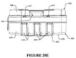
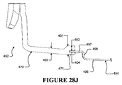
この実施形態において、加温板494には円形主要接触面495が設けられ、これは水槽452の、それを取り囲むプラスチック基底面470から突出し、それを越えて延び、チャンバが加湿コンパートメントの底の相補的な形状の加熱パッドの上に載った時に十分な係合と熱伝導を促進するように構成される。この実施形態において、加温板はさらに、主要接触表面部分495の周辺に沿って延びる直立または実質的に垂直な壁部分496と、加温板の周辺に沿って壁部分496の上部から外側に延びる、実質的に水平な外側周辺連結面またはレッジ部分497を含む。図のように、主要接触面部分495と外側連結レッジ497は実質的に平行な平面内に延びるが、垂直壁部分496の高さだけ相互に縦方向にずれている。図のように、基底面470の中央開口部の周辺に沿って周囲のプラスチックにオーバーモールドにより連結または固定されるのは、加温板494の連結レッジ497である。特に、基底面470の中央開口部の周辺に沿った基底面材料の係合部分471は、加温板494の、その周辺全体に沿った連結レッジ497の少なくとも一部にオーバーモールドされる。
In this embodiment, the warming
図28Jを参照すると、この実施形態において、オーバーモールド工程は、基底面の係合部分471が基底面の残りの部分に関して厚さが変化するように構成される。この実施形態において、加温板494の連結レッジ497の少なくとも一部にオーバーモールドされる係合部分471の全体的厚さ401は、水槽の残りの基底面470の厚さ402より厚い。この構成は、成形後に基底面470のプラスチックを加温板の連結レッジ497から離れるように浮き上がる量を減らすのに役立ち、これが今度は、金属の加温板とプラスチックの基底面の間の遷移接合領域で硬水の沈着物が進入する量を減少させる。1つの構成において、係合部分471の、加温板494の連結レッジ497より上の上側部分の厚さ403は、残りの基底面の厚さ402と同等か、または少なくとも同じで、上側部分が連結レッジ497の浮き上がりを減少させ、または最小化する。図のように、この実施形態において、係合部分471の、連結レッジ497より下の下側部分の厚さ404は、基底面470の係合部分471の上側部分の厚さ403より薄い厚さであってもよい。代替的実施形態において、係合面の下側部分の厚さ404はまた、残りの基底面の厚さ402と同等または、少なくとも同じ厚さであり、連結レッジ〜の下側部分の浮き上がりを減少させ、または最小化する。
Referring to FIG. 28J, in this embodiment, the overmolding process is configured such that the basal
当然のことながら、代替的実施形態において、加温板は実質的に平坦な円形の板であってもよく、これが基底面の中央開口部の中にオーバーモールドによって固定され、前述のように突出するのではなく、基底面の残りの部分と実質的に平らとなる。 Of course, in an alternative embodiment, the warming plate may be a substantially flat circular plate that is secured by overmolding in the central opening in the basal plane and protrudes as described above. Rather, it is substantially flat with the rest of the basal plane.
図28Lを参照すると、この実施形態において、水槽452にはまた、連続する水平の段差形成部472が設けられ、これは側壁内面の周辺に沿って延びる。段差形成部は、内周に沿って水槽の基底面から均一な高さだけずれている。段差形成部は側壁と一体に形成され、図28Iに示されるように、傾斜した段差の形態であってもよい。この構成において、段差形成部472は基底面からの、最高水位線に対応する高さに配置される。チャンバの蓋が開位置にある時、使用者は、給水穴を使用する代わりの選択肢として、水槽に水を段差形成部の高さまで注入してもよい。
Referring to FIG. 28L, in this embodiment, the
蓋
第三の実施形態の加湿チャンバ400の蓋456は、前述の実施形態の蓋56と実質的に同様であるが、いくつかの主要な相違点があり、これについて以下に説明する。これも当然のことながら、第三の実施形態の加湿チャンバはまた、前述のものと同じ蓋56を使用することもできる。
Lid The
図28C、28I、28Lを参照すると、この実施形態において、蓋456には図24Aと24Bに関して前述した種類のタブ型水位表示器220が設けられている。特に、タブ型水位表示器220は傾斜タブ134を含み、これは給水開口部120の下に、各端において直立支持部材132、221によって吊り上げられている。この実施形態において、最高(maximum)を意味する標識「MAX」が図28Lに示されるようにタブ部分134の下面に裏返しに印刷される。少なくともタブ部分134は透明なプラスチックで形成され、それによって標識「MAX」は、給水穴120を通した見た時に使用者にとって正しく読むことのできるフォーマットで見える。
Referring to FIGS. 28C, 28I, 28L, in this embodiment, the
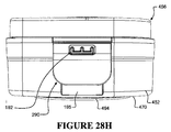
図28Eと28Cを参照すると、蓋456の入口側周壁106には1つまたは複数の突起407、例えば、周壁の表面から延びる隆起や隆条または形成部が設けられる。この実施形態において、突起407は蓋の中央入口開口部140の各側に設けられ、加湿コンパートメントの内側入口ガス側壁に設けられた、位置整合するレールと係合し、ここで、これについて説明する。図28Oを参照すると、加湿コンパートメント800の下側部分が示されており、これは加湿チャンバ400を受け、保持する相補的窩洞802を有する形状と寸法である。加湿コンパートメントの下側部分は、前述の種類の呼吸装置の筐体または本体の一部であってもよい。図2に関して前述したように、加湿コンパートメントは、加湿チャンバ400がこの窩洞内に取り付けられた時に、コンパートメントを密閉し、または囲い込む、開放可能な蓋をさらに含んでいてもよい。図のように、2つの垂直レール406が加湿コンパートメントの内壁面から、図2に関して前述した呼吸装置のブロワからのガスの流れを受けるガス入口804の両側で突出する。この実施形態において、各レール806はガス入口804の高さの、またはその付近の第一の上側端とコンパートメントの床面の、またはその付近の第二の下側端から延びる。この実施形態において、図28Oと28Tを参照すると、各レールは第一の短い開始傾斜部分806aを含み、これは壁面から外側に向かってテーパが付けられ、または傾斜し、その後、第二の、より長い戻り傾斜部分806bへと延び、これは再び内壁面に向かってテーパが付けられ、または傾斜する。動作中、加湿チャンバ400のガス入口側の突起407は、加湿コンパートメントの入口側にある係合レール806と位置整合する。加熱チャンバ400が加湿コンパートメントの中へと下ろされ、または挿入されると、突起407はそのそれぞれのレール806と当接または係合し、レールがチャンバ400を、コンパートメントの、図28Pに示されているガス出口808を含む反対の出口側壁に向かって付勢する。この構成は、チャンバが完全に挿入され、または取り付けられた時に、チャンバのガス出口をコンパートメントのガス出口808と密閉状態で係合または接続されるように付勢し、保持するのを助ける。この構成では、コンパートメントのガス出口808にシール材810が設けられ、これはガス出口808の周辺に沿って延びる。シール材は、例えばエラストマまたはゴムの構成要素またはインサートであってもよい。次に説明するように、この実施形態において、チャンバのガス出口150には係合面430が設けられ、これはガス出口808の周辺に沿ってシール材810と密閉状態で係合し、それによって出口間が密閉状態で接続される。代替的実施形態において、当然のことながら、シール材はチャンバのガス出口150に設けられてもよく、またはチャンバとコンパートメントの出口の両方が相補的なシール材を有していてもよい。
Referring to FIGS. 28E and 28C, the inlet side
図28F、28K、28P〜28Sを参照すると、第三の実施形態の加湿チャンバ400において、蓋456の出口側周壁108にあるガス出口150は、開口部150の周辺に沿って係合面または形成部430を含む。係合面430は、加湿チャンバ400がコンパートメント内に取り付けられた時に、加湿コンパートメント800のガス出口808のシール材810と密閉状態で係合するように構成される。この実施形態において、ガス出口150は実質的に長方形であり、したがって係合面430もまた実質的に長方形で、ガス出口150の上側および下側周辺に沿って延びる上側水平部分431と下側水平部分432と、ガス出口150の側方周辺部分に沿った側方垂直部分433、434を含む。この実施形態において、係合面430は、ガス出口150の周囲または周辺に沿って実質的に平坦であり、それによって加湿コンパートメント800のガス出口808に関連する相補的なシール材または出口面と密閉状態で係合してもよい。図の構成において、係合面430は好ましくは、垂直出口側周壁108に関して外側に傾斜し、または傾く。特に、図28Kにおいてより明瞭に示されているように、係合面430は、上側部分431が出口側周壁108から、下側部分432よりさらに外側にずれるように傾斜している。この構成において、係合面430は、その表面を横切って延びる水平軸の周囲で外側に傾きまたは旋回すると考えることができ、それによって係合面の上側部分は、蓋456の出口側周壁108から、係合面の下側部分または領域432より外側に突出し、またはずれるようになっている。当然のことながら、ガス出口と係合面が円形またはそれ以外の形状であっても、同じ原理が当てはまる。傾斜した係合面430は、加湿チャンバが相補的な加湿コンパートメント800の中に容易に受けられ、または挿入されるようにするのを支援し、チャンバのガス出口150と加湿コンパートメント800のガス出口808の間を密閉状態に係合または接続するのを助ける。
Referring to FIGS. 28F, 28K, and 28P to 28S, in the
図28Lを参照すると、蓋456の垂直流れパネル146が前述の実施形態に関して改良されている。この実施形態において、垂直パネルまたは面146はさらに、1対のバッフル部分または翼435を含み、これらは流れパネル146の側縁146に沿って、流れパネルの全高(H)にわたって延び、流れ偏向器またはガイドとして機能する。サイドバッフル435は流れパネル146の第一の側面146bから遠ざかるように、その側端の各々に沿って突出し、または延びる。特に、サイドバッフル435は流れ面146に実質的に垂直に延び、それによってこれらは蓋の入口側に向かって延びる。この構成では、垂直流れパネル146のサイドバッフル435の幅W2(流れパネルの表面に垂直方向に延びる)は、垂直流れパネルの全幅Wより実質的に小さい。使用中、サイドバッフル部分または面435は、入口導管142から出た流れが垂直流れパネルの側端146eの周囲で直接ガス出口導管152に向かって流れる、加湿が減少する経路をたどるのを最小化または防止するように構成される。サイドバッフル435は空気が加湿チャンバの入口側に向かって再び循環するように強制または促進し、ガスがチャンバから出る前にチャンバの一般的な空気流れ循環路を長くして、水分吸収を増大させる。前述のように、流れパネル146の高さ(H)は一般に、それが水の表面の中に、入口導管142から出たガスが下端146aの下を通り、出口導管152へと直接ショートカットするのを防止するのに十分な深さまで突出または貫通するように構成される。
Referring to FIG. 28L, the
ヒンジとクリップ
前述のように、上側部品、すなわち蓋456は下側部品、すなわち水槽452にヒンジで連結または接続され、これらが、蓋が水槽から離れるように旋回する(蓋を開けて水槽に給水し、またはクリーニングすることができる)開位置と、蓋が旋回して水槽と係合し、チャンバを閉じる閉位置の間で移動できるようになっている。この実施形態において、蓋456は水槽452に、前述の実施形態の蓋と受け皿の間のヒンジ結合と同様の方法でヒンジ結合される。特に、蓋456はチャンバの後方にあるヒンジの周囲で例えば、図28Aと28Bに示される閉位置または状態と、図28L〜28Nに示される開位置または状態の間で旋回可能である。図28A、28G、28Mに示されるように、この実施形態において、ヒンジは1つの長いリビングヒンジ160であり、これは加湿チャンバの後端の一部に沿って蓋456と水槽452の間に延び、前述の実施形態で上述した形態である。
Hinge and Clip As mentioned above, the upper part, i.e. the
加湿チャンバを閉状態に固定するために、1つまたは複数の操作可能クリップまたはクリップ機構が設けられ、チャンバを閉位置に固定するラッチまたはロック位置と、蓋456を水槽からと遠ざかって開位置または状態へと旋回させることのできるラッチ解除またはロック解除位置の間で操作可能である。図28B、28H、28M、28Nを参照すると、この実施形態において、加熱チャンバは、図23Aと23Bに関して説明した種類の1つの操作可能クリップ290と相補的な留め具形成部192を含む。特に、クリップ290は、蓋に旋回可能に取り付けられ、留め具192と係合するように移動可能で、チャンバをしっかりと閉じるか、留め具192から外れ、または釈放されて、チャンバを開けられるようにしてもよい。図28Hに示されるように、凹部195が水槽452の前壁の、クリップ290の付近に設けられ、使用者は希望に応じてタブを把持して引き、クリップを留め具形成部192から外すことができるようになっている。
To secure the humidification chamber in the closed state, one or more operable clips or clip mechanisms are provided, a latch or lock position that secures the chamber in the closed position, and a
シーリング
前述の実施形態と同様に、第三の実施形態のチャンバ400は必ずしも蓋456と水槽452の間で密閉される必要はない。しかしながら、希望に応じて、この実施形態に示されるように密閉されてもよい。図28Iを参照すると、蓋456のレッジ105には、周辺溝または凹部が設けられ、またはこれを形成し、図36の実施形態について説明された構成と同様に、シール材99が蓋の周辺に沿って溝の中に取り付けられる。図のように、シール材99はチャンバが閉じられた時に水槽452の周壁の上面またはリム461と係合して、チャンバを密閉する。他の構成では、図36に関して説明したその他の密閉構成を使用してもよい。
Sealing Similar to the previous embodiment, the
第四の実施形態の加湿チャンバ−スリーブを使用
図29Aと29Bを参照すると、第四の実施形態の加湿チャンバ500は第二の実施形態の加湿チャンバ300の変化形である。この実施形態において、蓋56は一方の端において、連続型受け皿にヒンジ結合されず、図のように水槽54の周壁全体を取り囲む、またはその周囲に延びる連続的周壁の形態のスリーブ552にヒンジ結合される。特に、スリーブ552は水槽の基底面54の全体を露出したままにする。スリーブ552は好ましくは、蓋56と同じ材料から形成され、好ましくはプラスチックまたは同様のものから射出成形される。554で示されるスリーブの高さは、希望に応じて様々であってもよい。この実施形態において、スリーブは実質的に水槽のリムの上縁から水槽の基底面まで延びるが、代替的実施形態においては、より薄く、上縁から周壁の途中までしか延びていなくてもよい。図29Bに示されるように、スリーブは、水槽54の上縁から外側に延びるリップまたはリム92によって、水槽54から浮き上がり、または滑って外れるのが防止される。それ以外は、加湿チャンバは前述の実施形態と実質的に同様であり、蓋をスリーブ552に後端(図示せず)に沿って連結するリビングヒンジと前方にクリップ機構560が設けられ、これは、この実施形態においては図21A〜21Cに関して説明した形態である。
Use of Humidification Chamber-Sleeve of Fourth Embodiment Referring to FIGS. 29A and 29B, the
第五の実施形態の加湿チャンバ−内部クリップを使用
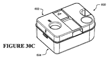
図30A〜30Cを参照すると、第五の実施形態の加湿チャンバ600(図30C参照)は、内部クリップを介して金属製水槽604(図30B参照)に釈放可能に連結されるプラスチックの蓋602を含む。プラスチックの蓋602は前述の実施形態の蓋と実質的に同様であるが、若干異なる水位表示器の構成を含む。特に、蓋の一方の端の付近の中央に配置された給水穴606と、蓋の反対の端の1つの角部の付近に配置された円錐水位表示器608がある。これに加えて、指掛け用凹部610が蓋の水位表示器側の端の中央に設けられる。蓋602の内部構造は、それ以外の点で、ガス入口、ガス出口、垂直流れ面の構成を含め、同様である。
Humidification Chamber of Fifth Embodiment—Use Internal Clip Referring to FIGS. 30A to 30C, the humidification chamber 600 (see FIG. 30C) of the fifth embodiment is connected to a metal water tank 604 (see FIG. 30B) via the internal clip. A
水槽604は全体が金属、例えばステンレススチール、アルミニウムまたはこれに類するものから形成される。任意選択により、プラスチックまたはその他の断熱材等の断熱材料のスリーブまたは受け皿を金属の水槽の外側周壁および/または下面に設けて、使用者が金属タブを持った時の手のやけどを防止してもよいが、使用者は、金属製の水槽を、蓋を介して、給水用開口部606と指掛け凹部610を例えば1本の指と親指で掴むことによって取り上げてもよい。
The
蓋602は水槽604にヒンジ結合されず、水槽から完全に取り外し可能である。蓋の各端にはクリップまたは係合突起612(一方の端のみ見える)が設けられ、これらは、水槽604の各端において、水槽の上縁に、またはその付近に設けられた相補的な凹部614と係合するように構成される。蓋602と水槽604を組み立てるには、使用者は蓋を押して、クリップ形成部612を相補的凹部614と係合させる必要がある。蓋を外すには、使用者はクリップ形成部612を凹部614から外すのに十分な力で、蓋を水槽から垂直方向に引く。
The
第六の実施形態の加湿チャンバ−ダクト付蓋を使用
図31A〜35を参照しながら、第六の実施形態の加湿チャンバ700を説明する。この実施形態はプラスチックの蓋702を含み、これは、第五の実施形態の加湿チャンバ600について上述した方法と同様に、相補的な形状の金属製水槽704に留め付けられる。図31Aは加湿チャンバの入口開口部706を示し、図31Bは加湿チャンバのガス出口708を示す。
Humidification chamber of sixth embodiment-using lid with duct
図32を参照すると、この実施形態において、水槽は金属またはその他の熱伝導材料で形成され、それが加温ベースに直接接触するか、その上に載るようになっている。係合用開口部710が水槽の各端に設けられ、蓋702に設けられた相補的な弾性クリップ730を受け、蓋を水槽に固定する。ガス入口706は水槽の1つの側の周壁の、水槽の上縁の角部の付近に設けられた開口部であるが、これは中央に、またはそれ以外に配置されてもよい。水槽の反対の側には、切欠きまたは凹部712が設けられ、その中に、蓋が水槽と係合して閉じられた、または組み立てられた状態の時に、蓋のガス出口708が入ってもよい。
Referring to FIG. 32, in this embodiment, the aquarium is made of metal or other heat conducting material so that it directly contacts or rests on the warming base.
図33〜35を参照すると、蓋702は上側枠部材714を含み、これは内部垂直壁718を介して下側枠部材716に連結される。内壁は、蓋の周辺に沿って枠部材714、716の縁から内側に引っ込められ、またはずれていて、水槽704と係合した時に蓋の内部の外周の実質的部分に沿って外周ガス流路が形成されるようになっている。ガスが入口706から外周通路に入ると、ガスは通路に沿って流れ、蓋の内壁718を通って形成される、一連の1つまたは複数の内側入口開口部720を介して加湿チャンバの内部空間に入る。この実施形態において、入口開口部720の大部分が入口側の壁に設けられているが、1つまたは複数の開口部が内壁の周囲面全体に沿って延びていてもよく、これは、見えないが、図35において720で示されるように、端壁と、出口に隣接して配置された反対側の壁を含む。それに加えて、またはその代わりに、入口開口部は蓋の周囲の少なくとも一部に沿って、下側枠部材716に設けることもできる。
33-35, the
図35を参照すると、蓋の、内部周壁718の内側の内面または下面には、各内側入口開口部720に関連する垂直流れ面722の構成が設けられ、これは入ってくるガスストリームを強制的に加湿チャンバの空間へと誘導し、加湿工程を促進する。ガス出口708は出口導管724を含み、これは開口部708から蓋の内部空間へと水平に延び、入口開口部726で終了し、それによって加湿ガスが出口導管724に入り、ガス出口708を通って加湿チャンバから出ることができる。図33を参照すると、蓋702の各端の中央には弾性ばねクリップ730が設けられ、これは水槽の相補的な係合用開口部710と係合して蓋を水槽に固定するように構成されたクリップ形成部732を含む。
Referring to FIG. 35, the inner or lower surface of the lid on the inner
実施形態
1.水の塊を受けるように構成された水槽と、水槽を受けるための開放窩洞を画定する受け皿と、水槽を囲い込み、加湿チャンバの内部空間を画定するために受け皿にヒンジ結合される蓋であって、水槽が蓋によって閉じられる閉位置と水槽が開く開位置との間で移動可能な蓋と、蓋を閉位置に固定するための1つまたは複数の操作可能クリップと、加湿チャンバの内部空間へとガスの流れを受けるためのガス入口と、そこを通って加湿ガスの流れが加湿チャンバの内部空間から出るガス出口と、を含む、ガスを加湿するための加湿チャンバ。
2.蓋と受け皿が剛性プラスチックで形成される、1項に記載の加湿チャンバ。
3.蓋と受け皿がリビングヒンジによってヒンジ結合され、1つの部品として一体に形成される、1項または2項に記載の加湿チャンバ。
4.水槽が熱伝導性材料で形成される、1項〜3項の何れか1項に記載の加湿チャンバ。
5.水槽が金属で形成される、4項に記載の加湿チャンバ。
6.水槽が基底面と、基底から上方に延びる周壁により画定され、受け皿が相補的な基底面および上方に延びる周壁を含み、受け皿の周壁が受け皿の周辺に沿って不連続であり、受け皿内に保持される水槽の周壁の1つまたは複数の部分が露出する、1項〜5項の何れか1項に記載の加湿チャンバ。
7.熱伝達接触面が水槽の基底面から突出し、受け皿には相補的な、位置整合する開口部が設けられ、ここを通って水槽の接触面が延び、それが受け皿の基底面の下面を越えて突出する、6項に記載の加湿チャンバ。
8.水槽がスライド係合によって受け皿内に取り外し可能に受けられる、1項〜7項の何れか1項に記載の加湿チャンバ。
9.ガス入口とガス出口が蓋のそれぞれ反対側に設けられる、1項〜8項の何れか1項に記載の加湿チャンバ。
10.蓋が、蓋の中央領域において蓋の下側から下方に延びる垂直流れ面を含む、9項に記載の加湿チャンバ。
11.ガス入口が入口導管に連結され、これがガス入口の入口端と加湿チャンバの内部空間の上側中央領域に、またはその付近に配置され、垂直流れ面の第一の側の面に隣接する出口端との間に延び、それによって入ってくるガスの流れが加湿チャンバの内部空間に、その上側中央領域において進入する、10項に記載の加湿チャンバ。
12.反転湾曲傾斜面の形態の流れ誘導形成部が入口導管の出口端と垂直流れ面の第一の側の面の間に配置される、11項に記載の加湿チャンバ。
13.ガス出口が出口導管に連結され、これが加湿チャンバの内部空間の上側中央領域に、またはその付近に配置され、垂直流れ面の第二の側に隣接する入口端とガス出口の出口端との間に延びる、11項または12項の何れか1項に記載の加湿チャンバ。
14.蓋が、1つまたは複数の給水用開口部と、蓋の下面から支持され、加湿チャンバの内部空間の視野の中へと延びて、給水用開口部を通じて直接見えるタブ部材を含む、関連する最高水位表示器を含む少なくとも1つの給水用開口部と、を含む、1項〜13項の何れか1項に記載の加湿チャンバ。
15.加湿チャンバの全体的形状が、間に側壁が延びる前および端壁によって画定され、これらの壁が蓋の上面と受け皿の基底面の間に延び、蓋が加湿チャンバの後端において受け皿にヒンジ結合され、少なくとも1つの操作可能クリップが加湿チャンバの前端に設けられる、1項〜14項の何れか1項に記載の加湿チャンバ。
16.少なくとも1つの操作可能クリップが、蓋または受け皿の何れかに取り付けられ、それぞれ受け皿または蓋の何れかに設けられた留め具と係合するように構成されるトーションクリップの形態で提供される、1項〜15項の何れか1項に記載の加湿チャンバ。
17.少なくとも1つの操作可能クリップが設けられ、これが蓋または受け皿にヒンジ結合され、それぞれ受け皿または蓋の何れかに設けられた留め具と係合するように構成される、1項〜15項の何れか1項に記載の加湿チャンバ。
18.水の塊を受けるように構成された水槽と、水槽を囲い込み、加湿チャンバの内部空間を画定するために水槽にヒンジ結合される蓋であって、水槽が蓋によって閉じられる閉位置と水槽が開く開位置との間で移動可能な蓋と、蓋を閉位置に固定するための1つまたは複数の操作可能クリップと、加湿チャンバの内部空間へとガスの流れを受けるためのガス入口と、そこを通って加湿ガスの流れが加湿チャンバの内部空間から出るガス出口と、を含む、ガスを加湿するための加湿チャンバ。
19.蓋が剛性プラスチックから形成される、18項に記載の加湿チャンバ。
20.水槽が剛性プラスチックで形成され、基底面と、基底から上方に延びる周壁と、を含み、基底面が加温板を含む、18項または19項に記載の加湿チャンバ。
21.加温板が水槽の基底面の開口部の内部にオーバーモールドによって固定される、20項に記載の加湿チャンバ。
22.加温板の周辺連結面が基底面の周辺係合部分の中に、水槽の開口部の周囲で、オーバーモールドによって固定され、それによって係合部分の厚さが残りの基底面の厚さより厚い、21項に記載の加湿チャンバ。
23.係合部分が、加温板の連結面より上の上側部分と連結面より下の下側部分を含み、上側部分が少なくとも残りの基底面と同じ厚さである、22項に記載の加湿チャンバ。
24.加温板が金属製である、20項〜23項の何れか1項に記載の加湿チャンバ。
25.水槽の壁の内面周辺に沿った段差形成部をさらに含み、段差形成部が、水槽の基底面より上の、最高給水線表示器に対応する高さに形成される、20項〜24項の何れか1項に記載の加湿チャンバ。
26.水槽の基底面がドーム状であり、それによってこれが加温板により画定される中心頂点に向かって外側に湾曲する、20項〜25項の何れか1項に記載の加湿チャンバ。
27.水槽の周壁が1つまたは複数の補強領域を含む、20項〜26項の何れか1項に記載の加湿チャンバ。
28.周壁の補強領域が、畝と溝を交互に有する波形表面を含む、27項に記載の加湿チャンバ。
29.蓋と水槽がリビングヒンジによってヒンジ結合され、1つの部品として一体に形成される、18項〜28項の何れか1項に記載の加湿チャンバ。
30.ガス入口とガス出口が蓋のそれぞれ反対側に設けられる、18項〜29項の何れか1項に記載の加湿チャンバ。
31.蓋が蓋の中央領域において蓋の下面から下方に延びる垂直流れ面を含む、30項に記載の加湿チャンバ。
32.垂直流れ面が、1対のサイドバッフルをさらに含み、その各々が垂直流れ面のそれぞれの側端から、蓋の、ガス入口を含む側に向かって延びる、31項に記載の加湿チャンバ。
33.ガス入口が、ガス入口の入口端と加湿チャンバの内部空間の上側中央領域に、またはその付近に配置され、垂直流れ面の第一の側の面に隣接する出口端との間に延びる入口導管に連結され、それによって入ってくるガスの流れが加湿チャンバの内部空間に、その上側中央領域において進入する、31項または32項に記載の加湿チャンバ。
34.反転湾曲傾斜面の形態の流れ誘導形成部が入口導管の出口端と垂直流れ面の第一の側の面の間に配置される、33項に記載の加湿チャンバ。
35.ガス出口が、加湿チャンバの内部空間の上側中央領域に、またはその付近に配置され、垂直流れ面の第二の側に隣接する入口端とガス出口の出口端との間に延びる出口導管に連結される、33項または34項に記載の加湿チャンバ。
36.蓋のガス出口が、ガス出口の周辺に沿って係合面を含み、これが外側に傾斜し、それによって係合面の上側部分が係合面の下側部分より蓋から外側にずれる、18項〜35項の何れか1項に記載の加湿チャンバ。
37.蓋が、1つまたは複数の給水用開口部と、蓋の下面から支持され、加湿チャンバの内部空間の視野の中へと延びて、給水用開口部を通じて直接見えるタブ部材を含む、関連する最高水位表示器を含む少なくとも1つの給水用開口部と、を含む、18項〜36項の何れか1項に記載の加湿チャンバ。
38.加湿チャンバの全体的形状が、間に側壁が延びる前および後端壁によって画定され、これらの壁は蓋の上面と水槽の基底面の間に延び、蓋は加湿チャンバの後端において水槽にヒンジ結合され、少なくとも1つの操作可能クリップが加湿チャンバの前端に設けられる、18項〜37項の何れか1項に記載の加湿チャンバ。
39.少なくとも1つの操作可能クリップが、蓋または水槽の何れかに取り付けられ、それぞれ水槽または蓋の何れかに設けられた留め具と係合するように構成されるトーションクリップの形態で提供される、18項〜38項の何れか1項に記載の加湿チャンバ。
40.蓋または水槽にヒンジ結合され、それぞれ水槽または蓋の何れかに設けられた留め具と係合するように構成される少なくとも1つの操作可能クリップが設けられる、18項〜39項の何れか1項に記載の加湿チャンバ。
41.蓋と水槽の間に、加湿チャンバの周辺に沿ってシール材をさらに含み、閉位置にある時にチャンバを密閉する、18項〜40項の何れか1項に記載の加湿チャンバ。
42.ガスの供給を受けるように構成された装置ガス入口と、ガス供給から加圧ガスのストリームを生成するように構成されるブロワと、加圧ガスのストリームを加温加湿するように構成された加湿器と、加温加湿ガスのストリームのための装置ガス出口と、呼吸装置を通ってガス入口からブロワユニットおよび加湿ユニットを通り、ガス出口に至るガスのストリームのための流路と、を含み、加湿器が、1項〜41項の何れか1項に記載の取り外し可能な加湿チャンバを受け、保持するように構成される密閉可能な加湿コンパートメントを含む、加温加湿ガスのストリームを提供するように構成される呼吸補助装置。
43.加湿コンパートメントが、加湿チャンバを取り外せる開位置と加湿コンパートメント内の加湿チャンバを密閉する閉位置の間で移動可能な蓋を含む、42項に記載の呼吸補助装置。
44.加湿コンパートメントが、流路に接続され、ブロワからの加圧ガスのストリームを受け取り、加圧された加湿コンパートメントを作るガス入口と、流路の装置ガス出口に接続されたガス出口と、を含む、42項または43項に記載の呼吸補助装置。
45.加湿チャンバのガス入口が加湿コンパートメント内で開き、加圧された加湿コンパートメント内から入ってくるガスの流れを受け取る、44項に記載の呼吸補助装置。
46.加湿コンパートメントのガス出口が加湿チャンバのガス出口に密閉状態で接続される、44項または45項に記載の呼吸補助装置。
47.加湿コンパートメントが加温パッドを含み、その上に加湿チャンバが載る、42項〜46項の何れか1項に記載の呼吸補助装置。
48.装置が1つの筐体内に収容される、42項〜47項の何れか1項に記載の呼吸補助装置。
49.装置がCPAP呼吸装置である、42項〜48項の何れか1項に記載の呼吸補助装置。
Embodiment 1. FIG. A water tank configured to receive a mass of water, a saucer defining an open cavity for receiving the water tank, and a lid that surrounds the water tank and is hinged to the saucer to define an interior space of the humidification chamber. A lid movable between a closed position in which the aquarium is closed by the lid and an open position in which the aquarium opens, one or more operable clips for securing the lid in the closed position, and into the interior space of the humidification chamber And a gas inlet for receiving a flow of gas, and a gas outlet through which the flow of humidified gas exits the interior space of the humidifying chamber.
2. The humidification chamber according to claim 1, wherein the lid and the tray are formed of rigid plastic.
3. Lid and pan are hinged by a living hinge are formed integrally in one piece, the humidification chamber according to item 1 or 2 wherein.
4). The humidification chamber according to any one of items 1 to 3, wherein the water tank is formed of a heat conductive material.
5. The humidification chamber according to
6). The aquarium is defined by a base surface and a peripheral wall extending upward from the base, and the saucer includes a complementary base surface and an upwardly extending peripheral wall, and the peripheral wall of the saucer is discontinuous along the periphery of the saucer and is held in the saucer The humidification chamber according to any one of claims 1 to 5, wherein one or more portions of the peripheral wall of the water tank to be exposed are exposed.
7). The heat transfer contact surface protrudes from the base of the aquarium and the tray is provided with a complementary, aligned opening through which the tank contact surface extends, beyond the bottom of the base of the tray. The humidification chamber according to claim 6, which protrudes.
8). The humidification chamber according to any one of claims 1 to 7, wherein the water tank is detachably received in the tray by sliding engagement.
9. The humidification chamber according to any one of 1 to 8, wherein a gas inlet and a gas outlet are provided on opposite sides of the lid, respectively.
10. The humidification chamber of
11. A gas inlet is connected to the inlet conduit, which is disposed at or near the inlet end of the gas inlet and the upper central region of the interior space of the humidification chamber and is adjacent to the first side surface of the vertical flow surface; The humidification chamber according to
12 12. A humidification chamber according to
13. A gas outlet is connected to the outlet conduit, which is located in or near the upper central region of the interior space of the humidification chamber and between the inlet end adjacent to the second side of the vertical flow surface and the outlet end of the
14 The lid includes one or more water supply openings and a tab member that is supported from the underside of the lid and extends into the field of view of the interior space of the humidification chamber and is directly visible through the water supply opening. 14. A humidification chamber according to any one of claims 1 to 13, comprising at least one water supply opening including a water level indicator.
15. The overall shape of the humidification chamber is defined by front and end walls extending between the side walls, which extend between the top surface of the lid and the base surface of the saucer, and the lid is hinged to the saucer at the rear end of the humidification chamber 15. The humidification chamber according to any one of claims 1 to 14, wherein at least one operable clip is provided at the front end of the humidification chamber.
16. At least one operable clip is provided in the form of a torsion clip attached to either the lid or the saucer and configured to engage a fastener provided on either the saucer or the lid, respectively. Item 16. The humidification chamber according to any one of Items 15 to 15.
17. 16. Any of paragraphs 1-15, wherein at least one operable clip is provided, which is hinged to the lid or tray and is configured to engage a fastener provided on either the tray or lid, respectively. The humidification chamber according to claim 1.
18. A water tank configured to receive a mass of water, and a lid hinged to the water tank to enclose the water tank and define an interior space of the humidification chamber, wherein the water tank is closed by the lid and the water tank opens A lid movable between the open position, one or more operable clips for securing the lid in the closed position, a gas inlet for receiving a gas flow into the interior space of the humidification chamber, and A humidification chamber for humidifying the gas, comprising a gas outlet through which a flow of humidified gas exits the interior space of the humidification chamber.
19. 19. A humidification chamber according to claim 18, wherein the lid is formed from rigid plastic.
20. 20. The humidification chamber according to item 18 or 19, wherein the water tank is formed of a rigid plastic, includes a base surface and a peripheral wall extending upward from the base, and the base surface includes a heating plate.
21. Item 21. The humidification chamber according to
22. The peripheral connecting surface of the heating plate is fixed by the overmold around the water tank opening in the peripheral engaging portion of the base surface, so that the thickness of the engaging portion is thicker than the thickness of the remaining base surface The humidification chamber according to claim 21.
23. 23. The humidification chamber according to
24. 24. The humidification chamber according to any one of
25. 24. The method according to
26. 26. A humidification chamber according to any one of
27. 27. The humidification chamber according to any one of
28. 28. The humidification chamber of claim 27, wherein the peripheral wall reinforcement region includes a corrugated surface having alternating ridges and grooves.
29. Lid and water tank is hinged by a living hinge are formed integrally in one piece, the humidification chamber as claimed in any one of item 18 to 28 wherein.
30. 30. The humidification chamber according to any one of items 18 to 29, wherein a gas inlet and a gas outlet are provided on opposite sides of the lid, respectively.
31. 31. The humidification chamber of
32. 32. The humidification chamber of claim 31, wherein the vertical flow surface further includes a pair of side baffles, each extending from a respective side edge of the vertical flow surface toward the side of the lid that includes the gas inlet.
33. An inlet conduit, wherein the gas inlet extends between the inlet end of the gas inlet and the outlet end adjacent to the first side surface of the vertical flow surface, located at or near the upper central region of the interior space of the humidification chamber Item 33. The humidification chamber according to
34. 34. A humidification chamber according to claim 33, wherein a flow guide formation in the form of an inverted curved ramp is disposed between the outlet end of the inlet conduit and the first side surface of the vertical flow surface.
35. A gas outlet is located at or near the upper central region of the interior space of the humidification chamber and is connected to an outlet conduit extending between the inlet end adjacent to the second side of the vertical flow surface and the outlet end of the gas outlet 35. A humidification chamber according to
36. The gas outlet of the lid includes an engagement surface along the periphery of the gas outlet, which is inclined outward, whereby the upper portion of the engagement surface is displaced outward from the lid from the lower portion of the engagement surface. 36. A humidification chamber according to any one of -35.
37. The lid includes one or more water supply openings and a tab member that is supported from the underside of the lid and extends into the field of view of the interior space of the humidification chamber and is directly visible through the water supply opening. 37. The humidification chamber according to any one of items 18 to 36, comprising at least one water supply opening including a water level indicator.
38. The overall shape of the humidification chamber is defined by front and rear end walls extending between the side walls, which extend between the top surface of the lid and the base of the aquarium, the lid hinged to the aquarium at the rear end of the
39. At least one operable clip is provided in the form of a torsion clip attached to either the lid or aquarium and configured to engage a fastener provided on either the aquarium or lid, respectively. 40. The humidification chamber according to any one of
40. 40. Any one of paragraphs 18-39, wherein at least one operable clip is provided that is hinged to the lid or aquarium and is configured to engage a fastener provided on either the aquarium or the lid, respectively. A humidification chamber as described in 1.
41. 41. The humidification chamber according to any one of items 18 to 40, further comprising a sealant between the lid and the water tank along the periphery of the humidification chamber, and sealing the chamber when in the closed position.
42. A device gas inlet configured to receive a gas supply, a blower configured to generate a stream of pressurized gas from the gas supply, and a humidifier configured to warm and humidify the stream of pressurized gas And a device gas outlet for the stream of warm humidified gas, and a flow path for the stream of gas through the breathing device, from the gas inlet through the blower unit and humidifier unit to the gas outlet, A humidifier provides a stream of warmed humidified gas comprising a sealable humidified compartment configured to receive and hold a removable humidified chamber according to any one of paragraphs 1-41. Respiratory device configured to.
43. 43. A respiratory assistance device according to 42, wherein the humidifying compartment includes a lid that is movable between an open position where the humidifying chamber can be removed and a closed position which seals the humidifying chamber within the humidifying compartment.
44. A humidification compartment is connected to the flow path and includes a gas inlet receiving a stream of pressurized gas from the blower and creating a pressurized humidified compartment; and a gas outlet connected to the apparatus gas outlet of the flow path. 44. A respiratory assistance device according to
45. 45. A respiratory assistance device according to
46. 46. A breathing assistance device according to
47. 47. A respiratory assistance device according to any one of
48. 48. The respiratory assistance device according to any one of
49. 49. A respiratory assistance device according to any one of
本発明の上記の説明は、その好ましい形態を含む。これらには、付属の特許請求の範囲により定義される本発明の範囲から逸脱することなく、変更を加えることができる。 The above description of the invention includes preferred forms thereof. These can be modified without departing from the scope of the invention as defined by the appended claims.
Claims (15)
水の塊を受けるように構成され、基底面に加温板を有する水槽と、
前記水槽に前記加湿チャンバの後端において、前記水槽に対して軸周りに離脱することなく回転できるように1つまたは複数のヒンジ又は蝶着機構によって結合され、前記水槽を囲い込み、前記加湿チャンバの内部空間を画定する蓋であって、前記水槽が前記蓋によって閉じられる閉位置と前記水槽が開く開位置との間で移動可能な蓋と、
前記蓋を前記閉位置に固定するための1つまたは複数の操作可能クリップであって、前記蓋又は前記水槽の何れかに設けられており、前記蓋又は前記水槽の何れかに設けられた相補的な留め具と係合するように構成された、少なくとも一つの操作可能なクリップと、
前記加湿チャンバの前記内部空間へとガスの流れを受けるための前記蓋のガス入口であって、加湿チャンバの前記内部空間内にまで延びる、関連する入口導管を有するガス入口と、
そこを通って加湿ガスの流れが前記加湿チャンバの前記内部空間から出る前記蓋のガス出口であって、加湿チャンバの前記内部空間にまで延びる、関連する出口導管を有するガス出口を含む加湿チャンバ。 In a humidification chamber for humidifying the gas,
A water tank configured to receive a mass of water and having a heating plate on the base surface;
At the rear end of the humidification chamber, the water tank is coupled to the water tank by one or more hinges or a hinge mechanism so as to be able to rotate without detaching about the axis . A lid defining an internal space, the lid being movable between a closed position where the water tank is closed by the lid and an open position where the water tank is opened;
One or more operable clips for securing the lid in the closed position, provided on either the lid or the aquarium and complementary provided on either the lid or the aquarium At least one operable clip configured to engage with a static fastener;
A gas inlet of the lid for receiving a gas flow into the interior space of the humidification chamber, the gas inlet having an associated inlet conduit extending into the interior space of the humidification chamber;
A humidification chamber comprising a gas outlet with an associated outlet conduit through which a flow of humidified gas exits the interior space of the humidification chamber and extends to the interior space of the humidification chamber.
請求項1に記載の加湿チャンバ。 The lid is formed of a rigid plastic and / or the heating plate is formed of a thermally conductive material;
The humidification chamber according to claim 1.
請求項1または2に記載の加湿チャンバ。 The water tank is formed of rigid plastic, the heating plate is formed of metal, and the bottom surface of the base surface of the water tank is formed of a part of the rigid plastic and an exposed metal part of the heating plate,
The humidification chamber according to claim 1 or 2.
請求項1乃至3の何れか1項に記載の加湿チャンバ。 The basal plane of the water tank overlaps with a part of the heating plate such that a part of the lower surface of the basal plane is insulated from the heating plate.
The humidification chamber according to any one of claims 1 to 3.
請求項1乃至4の何れか1項に記載の加湿チャンバ。 The inlet conduit of the gas inlet of the lid is configured to flow or direct a flow of gas to a central region of the lid;
The humidification chamber of any one of Claims 1 thru | or 4.
請求項1乃至5の何れか1項に記載の加湿チャンバ。 The gas inlet of the lid has an inlet opening provided in a wall of the lid, and the inlet conduit extends to an inlet end disposed in the inlet opening and an upper central region of the internal space of the humidification chamber. Arranged or extending between the outlet end towards the upper central region,
The humidification chamber of any one of Claims 1 thru | or 5.
請求項6に記載の加湿チャンバ。 A flow guide formation is provided at the outlet end of the inlet conduit for inducing a flow of gas exiting the inlet conduit;
The humidification chamber according to claim 6.
請求項6又は7に記載の加湿チャンバ。 A vertical flow surface configured to minimize gas flowing out of the inlet conduit toward the outlet conduit of the gas outlet is further provided at or toward the outlet end of the inlet conduit. ,
The humidification chamber according to claim 6 or 7.
請求項1乃至8の何れか1項に記載の加湿チャンバ。 The inlet conduit includes one or more bends;
The humidification chamber according to any one of claims 1 to 8.
請求項1乃至9の何れか1項に記載の加湿チャンバ。 The gas outlet of the lid has an outlet opening provided in a wall of the lid, and the outlet conduit is arranged in an upper central region of the internal space of the humidification chamber or an inlet toward the upper central region Extending between an end and an outlet end disposed in the outlet opening,
The humidification chamber of any one of Claims 1 thru | or 9.
請求項1乃至10の何れか1項に記載の加湿チャンバ。 The humidification chamber has a front end and a rear end, and the lid is hinged to the aquarium at the rear end of the humidification chamber, the at least one operable clip and a fastener complementary to the clip Is provided at the front end of the humidification chamber,
The humidification chamber according to any one of claims 1 to 10.
請求項1乃至11の何れか1項に記載の加湿チャンバ。 The at least one operable clip has an engagement opening, and the complementary fastener of the clip is a protrusion or formation that aligns with the clip, so that the clip secures the lid in the closed position. When the clip is in the engagement position, the protrusion or the forming portion is engaged with the engagement opening of the clip.
The humidification chamber of any one of Claims 1 thru | or 11.
請求項12に記載の加湿チャンバ。 The fastener forming portion pivots or outwards the corresponding operable clip before being snapped into full engagement with the corresponding operable clip and the complementary fastener. Having a cam surface configured to bend;
The humidification chamber according to claim 12.
請求項1乃至10の何れか1項に記載の加湿チャンバ。 The humidification chamber has a front end and a rear end, the lid is hinged to the water tank at the rear end of the humidification chamber, and one operable clip is provided at the front end of the lid, The clip is elastically movable between the engagement position and the release position, and a complementary fastener is provided at the front end of the water tank.
The humidification chamber according to any one of claims 1 to 10.
請求項1乃至14の何れか1項に記載の加湿チャンバ。 In order to seal the chamber in the closed position, a seal is provided between the lid and the aquarium,
The humidification chamber of any one of Claims 1 thru | or 14.
Applications Claiming Priority (3)
| Application Number | Priority Date | Filing Date | Title |
|---|---|---|---|
| US201261697980P | 2012-09-07 | 2012-09-07 | |
| US61/697,980 | 2012-09-07 | ||
| PCT/NZ2013/000166 WO2014038968A1 (en) | 2012-09-07 | 2013-09-09 | Humidification chamber for a respiratory assistance apparatus |
Related Child Applications (1)
| Application Number | Title | Priority Date | Filing Date |
|---|---|---|---|
| JP2017239648A Division JP6685271B2 (en) | 2012-09-07 | 2017-12-14 | Humidification chamber for respiratory aids |
Publications (3)
| Publication Number | Publication Date |
|---|---|
| JP2015529525A JP2015529525A (en) | 2015-10-08 |
| JP2015529525A5 JP2015529525A5 (en) | 2019-09-26 |
| JP6599231B2 true JP6599231B2 (en) | 2019-10-30 |
Family
ID=50237452
Family Applications (5)
| Application Number | Title | Priority Date | Filing Date |
|---|---|---|---|
| JP2015531035A Active JP6599231B2 (en) | 2012-09-07 | 2013-09-09 | Humidification chamber for respiratory assistance device |
| JP2017239648A Active JP6685271B2 (en) | 2012-09-07 | 2017-12-14 | Humidification chamber for respiratory aids |
| JP2019208154A Active JP7059241B2 (en) | 2012-09-07 | 2019-11-18 | Humidification chamber for breathing aids |
| JP2022065885A Pending JP2022095870A (en) | 2012-09-07 | 2022-04-12 | Humidification chamber for respiratory assistance apparatus |
| JP2023196935A Pending JP2024014990A (en) | 2012-09-07 | 2023-11-20 | Humidification chamber for breathing assistance equipment |
Family Applications After (4)
| Application Number | Title | Priority Date | Filing Date |
|---|---|---|---|
| JP2017239648A Active JP6685271B2 (en) | 2012-09-07 | 2017-12-14 | Humidification chamber for respiratory aids |
| JP2019208154A Active JP7059241B2 (en) | 2012-09-07 | 2019-11-18 | Humidification chamber for breathing aids |
| JP2022065885A Pending JP2022095870A (en) | 2012-09-07 | 2022-04-12 | Humidification chamber for respiratory assistance apparatus |
| JP2023196935A Pending JP2024014990A (en) | 2012-09-07 | 2023-11-20 | Humidification chamber for breathing assistance equipment |
Country Status (9)
| Country | Link |
|---|---|
| US (6) | US10004871B2 (en) |
| EP (3) | EP2892598B1 (en) |
| JP (5) | JP6599231B2 (en) |
| AU (11) | AU2013313726B2 (en) |
| CA (1) | CA2883336A1 (en) |
| DE (1) | DE202013012358U1 (en) |
| HK (1) | HK1212639A1 (en) |
| SG (4) | SG11201605569TA (en) |
| WO (1) | WO2014038968A1 (en) |
Families Citing this family (36)
| Publication number | Priority date | Publication date | Assignee | Title |
|---|---|---|---|---|
| CN101690385B (en) | 2007-06-05 | 2015-05-27 | 瑞思迈有限公司 | Electrical heater with particular application to humification and fluid warming |
| EP2178590B1 (en) | 2007-07-18 | 2021-04-21 | Vapotherm, Inc. | System for delivering a heated and humidified gas |
| US8905023B2 (en) | 2007-10-05 | 2014-12-09 | Vapotherm, Inc. | Hyperthermic humidification system |
| US9505164B2 (en) | 2009-12-30 | 2016-11-29 | Schauenburg Technology Se | Tapered helically reinforced hose and its manufacture |
| DE102008022663B4 (en) | 2008-05-07 | 2012-10-31 | Schauenburg Hose Technology Gmbh | Stretch hose |
| US9964238B2 (en) | 2009-01-15 | 2018-05-08 | Globalmed, Inc. | Stretch hose and hose production method |
| EP3708213B1 (en) * | 2012-03-15 | 2022-11-02 | ResMed Pty Ltd | Heating apparatus |
| SG11201605569TA (en) | 2012-09-07 | 2016-08-30 | Fisher & Paykel Healthcare Ltd | Humidification chamber for a respiratory assistance apparatus |
| US9861778B2 (en) | 2013-03-15 | 2018-01-09 | Resmed Limited | Humidifier reservoir |
| EP3881887B1 (en) * | 2013-03-15 | 2023-11-15 | ResMed Pty Ltd | Respiratory pressure therapy device |
| NZ630751A (en) * | 2014-05-01 | 2016-03-31 | ResMed Humidification Technologies GmbH | Humidifying chamber for humidifying breathable gas |
| CN104368072B (en) * | 2014-11-28 | 2016-11-23 | 江苏鱼跃信息系统有限公司 | There is the little area water tank of circulative convection structure |
| USD784515S1 (en) | 2015-09-25 | 2017-04-18 | Fisher & Paykel Healthcare Limited | Headgear |
| USD828917S1 (en) * | 2015-09-25 | 2018-09-18 | Fisher & Paykel Healthcare Limited | Vent diffuser |
| USD784516S1 (en) | 2015-09-25 | 2017-04-18 | Fisher & Paykel Healthcare Limited | Face mask frame |
| USD800895S1 (en) | 2015-09-25 | 2017-10-24 | Fisher & Paykel Healthcare Limited | Face mask cushion |
| EP3452159A4 (en) * | 2016-05-02 | 2020-01-01 | Fisher&Paykel Healthcare Limited | Humidification chamber and chamber seal for a respiratory assistance apparatus |
| SG11201811303VA (en) | 2016-07-01 | 2019-01-30 | Fisher & Paykel Healthcare Ltd | Improvements relating to a respiratory device |
| US10527464B2 (en) | 2016-08-18 | 2020-01-07 | Ford Global Technologies, Llc | Rotatable sensor cover |
| USD797646S1 (en) * | 2016-08-18 | 2017-09-19 | Ford Motor Company | Sensor cover |
| USD838231S1 (en) | 2016-08-18 | 2019-01-15 | Ford Motor Company | Sensor cover |
| USD838230S1 (en) | 2016-08-18 | 2019-01-15 | Ford Motor Company | Sensor cover |
| USD809995S1 (en) | 2016-08-18 | 2018-02-13 | Ford Motor Company | Sensor cover |
| US11400247B2 (en) * | 2016-12-22 | 2022-08-02 | Fisher & Paykel Healthcare Limited | Breathing assistance apparatus |
| EP3597249B1 (en) | 2017-01-30 | 2023-02-15 | GlobalMed, Inc. | Heated respiratory hose assembly |
| FR3066698A1 (en) * | 2017-05-24 | 2018-11-30 | Air Liquide Medical Systems | IMPROVED WATER TANK FOR A HEATING GAS HUMIDIFIER POWERED BY A MEDICAL FAN |
| USD838364S1 (en) * | 2017-11-01 | 2019-01-15 | Fisher & Paykel Healthcare Limited | Humidification chamber seal |
| US11338105B2 (en) | 2018-03-27 | 2022-05-24 | Globalmed, Inc. | Respiratory humidification device |
| EP3586694A1 (en) * | 2018-06-28 | 2020-01-01 | Koninklijke Philips N.V. | A drip tray cover and a drip tray for use in a drinks machine |
| CN112569439A (en) * | 2018-10-26 | 2021-03-30 | 北京怡和嘉业医疗科技股份有限公司 | Respiratory ventilation apparatus |
| EP3848080A4 (en) * | 2018-10-26 | 2021-11-17 | BMC (Tianjin) Medical Co., Ltd. | Water tank mounting structure for ventilation treatment apparatus and ventilation treatment apparatus |
| EP3897798A4 (en) * | 2018-12-18 | 2022-09-07 | ResMed Pty Ltd | Humidifier reservoir |
| USD894371S1 (en) | 2019-03-01 | 2020-08-25 | Guardian Technologies Llc | Mist inhaler |
| MX2021012582A (en) | 2019-04-17 | 2022-01-18 | ResMed Pty Ltd | Cpap system. |
| USD957620S1 (en) | 2019-10-02 | 2022-07-12 | Fisher & Paykel Healthcare Limited | Liquid chamber |
| JP7347657B2 (en) * | 2020-04-08 | 2023-09-20 | 株式会社村田製作所 | humidifier |
Family Cites Families (84)
| Publication number | Priority date | Publication date | Assignee | Title |
|---|---|---|---|---|
| JPS49124849U (en) * | 1973-02-16 | 1974-10-25 | ||
| US4028444A (en) | 1974-03-25 | 1977-06-07 | Chemetron Corporation | Humidifier and automatic control system therefor |
| US4012473A (en) * | 1975-07-16 | 1977-03-15 | Arbrook, Inc. | Nebulizer-humidifier |
| US4203027A (en) | 1977-03-07 | 1980-05-13 | Fisher & Paykel Limited | Electrically heated humidifying apparatus |
| US4152379A (en) | 1977-05-26 | 1979-05-01 | Airco, Inc. | Anesthesia humidifier |
| JPS5516202U (en) * | 1978-07-14 | 1980-02-01 | ||
| US4261353A (en) | 1979-08-20 | 1981-04-14 | Bourns Medical Systems, Inc. | Humidifier filler |
| US4303601A (en) * | 1980-03-31 | 1981-12-01 | Baxter Travenol Laboratories, Inc. | Ventilator humidifier |
| JPS6174549A (en) | 1984-09-20 | 1986-04-16 | Oozeki Syuzo Kk | Preparation of feed |
| JPH0417490Y2 (en) * | 1984-10-19 | 1992-04-20 | ||
| US4676237A (en) | 1985-01-29 | 1987-06-30 | Boutade Worldwide Investments Nv | Inhaler device |
| JP3167708B2 (en) | 1990-06-30 | 2001-05-21 | 川崎重工業株式会社 | Method and apparatus for recovering generated gas energy from high pressure metallurgical furnace |
| US5209225A (en) * | 1991-11-19 | 1993-05-11 | Glenn Joseph G | Flow through nebulizer |
| JP3178227B2 (en) | 1994-03-18 | 2001-06-18 | 三菱自動車工業株式会社 | Suspension structure |
| US5564415A (en) * | 1995-06-07 | 1996-10-15 | Lifecare International, Inc. | Humidifier for a ventilator |
| EP0773172B1 (en) * | 1995-11-07 | 2000-07-12 | Societe Des Produits Nestle S.A. | Hinged closure for a container |
| DE19630466C2 (en) | 1996-07-27 | 1998-05-07 | Nikolaus Netzer | Device for supplying gas for sleep apnea |
| JPH10115905A (en) * | 1996-10-09 | 1998-05-06 | Dainippon Printing Co Ltd | Container for photographic print, film cartridge, and index print |
| JP3060967B2 (en) | 1996-10-16 | 2000-07-10 | タイガー魔法瓶株式会社 | humidifier |
| US5943473A (en) * | 1997-05-29 | 1999-08-24 | Levine; Walter | Heated cartridge humidifier |
| JPH11347126A (en) | 1998-06-05 | 1999-12-21 | Sumitomo Bakelite Co Ltd | Medical device for supplying oxygen enriched gas |
| US6398197B1 (en) * | 1999-05-10 | 2002-06-04 | Fisher & Paykel Limited | Water chamber |
| DE29909611U1 (en) | 1999-06-02 | 1999-09-02 | Hoffrichter Helmut | Arrangement for a heatable humidifier |
| AUPQ339099A0 (en) * | 1999-10-13 | 1999-11-04 | Resmed Limited | A humidifier |
| DE10049869A1 (en) * | 2000-10-10 | 2002-04-11 | Weinmann G Geraete Med | Respiration apparatus has heating element in region of water tank for humidifying air supplied for breathing |
| JP3591462B2 (en) * | 2001-02-02 | 2004-11-17 | タイガー魔法瓶株式会社 | humidifier |
| US7137388B2 (en) * | 2001-02-16 | 2006-11-21 | Resmed Limited | Air pressure signal monitoring in apparatus for treating sleep disordered breathing |
| JP4883544B2 (en) | 2001-05-18 | 2012-02-22 | 日本クラウンコルク株式会社 | Container with hinge lid made of different materials |
| US6994083B2 (en) | 2001-12-21 | 2006-02-07 | Trudell Medical International | Nebulizer apparatus and method |
| DE10163800A1 (en) | 2001-12-22 | 2003-07-03 | Heptec Gmbh | Vaporizer for ventilators and vaporizing process |
| JP2003231541A (en) * | 2002-02-06 | 2003-08-19 | Minoru Industrial Co Ltd | Plastic molded container |
| DE10226160B4 (en) * | 2002-06-12 | 2009-06-18 | Hoffrichter Gmbh | Humidifier for a ventilator |
| EP3639879B1 (en) | 2002-09-17 | 2020-11-11 | Fisher & Paykel Healthcare Limited | Apparatus for delivering humidified gases |
| JP4242639B2 (en) * | 2002-12-13 | 2009-03-25 | テルモ株式会社 | humidifier |
| AU2003903139A0 (en) * | 2003-06-20 | 2003-07-03 | Resmed Limited | Breathable gas apparatus with humidifier |
| CA3081288C (en) | 2003-06-20 | 2022-10-18 | ResMed Pty Ltd | Breathable gas apparatus with humidifier |
| CA2535974C (en) | 2003-08-20 | 2011-10-18 | Fisher & Paykel Healthcare Limited | Water chamber for humidifier |
| DE202004004115U1 (en) | 2004-03-15 | 2004-07-22 | Seleon Gmbh | Air humidifier for respiratory devices comprises a housing which is shaped so that its storage space is fillable with water through an air opening |
| DE102004037698A1 (en) | 2004-08-02 | 2006-03-16 | Seleon Gmbh | Evaporator as well as evaporation process |
| US7413173B2 (en) * | 2004-09-10 | 2008-08-19 | Ric Investments, Llc | Molded water chamber base plate for use in a humidifier and ventilator assembly |
| US7428902B2 (en) | 2004-12-15 | 2008-09-30 | Newport Medical Instruments, Inc. | Humidifier system for artificial respiration |
| DE102006034028A1 (en) | 2005-08-01 | 2007-02-08 | Weinmann Geräte für Medizin GmbH + Co. KG | Artificial respiration e.g. CPAP respiration, apparatus for use in clinic, has respired air humidifier comprising upper part not separable from lower part, and air outlet disposed at preset angle with respect to air inlet |
| EP1924312B1 (en) * | 2005-08-15 | 2016-06-29 | ResMed Limited | Humidifier tub for cpap device |
| US8522782B2 (en) | 2005-09-12 | 2013-09-03 | Mergenet Medical, Inc. | High flow therapy device utilizing a non-sealing respiratory interface and related methods |
| US7677246B2 (en) * | 2005-09-23 | 2010-03-16 | Ric Investments, Llc | Modular pressure support system |
| US7913985B2 (en) | 2006-03-09 | 2011-03-29 | Invacare Corporation | Cap |
| US20070235466A1 (en) * | 2006-04-07 | 2007-10-11 | Fulscher Ryan L | Portable dispenser |
| US7802739B2 (en) | 2006-06-15 | 2010-09-28 | Scorvo Sean K | Manually operable drain device |
| CA2959267C (en) | 2006-11-06 | 2020-06-23 | Fisher & Paykel Healthcare Limited | Integrated humidifier chamber and lid |
| EP2152344A1 (en) * | 2007-06-04 | 2010-02-17 | Compumedics Medical Innovation Pty Ltd | Water reservoir baffle |
| CN101690385B (en) * | 2007-06-05 | 2015-05-27 | 瑞思迈有限公司 | Electrical heater with particular application to humification and fluid warming |
| US8365726B2 (en) | 2007-06-07 | 2013-02-05 | Resmed Limited | Tub for humidifier |
| US8550075B2 (en) * | 2007-06-28 | 2013-10-08 | Resmed Limited | Removable and/or replaceable humidifier |
| DE102007037458B4 (en) * | 2007-08-08 | 2010-01-14 | Dräger Medical AG & Co. KG | respiratory humidifier |
| US20090301474A1 (en) * | 2008-06-05 | 2009-12-10 | Neil Alex Korneff | Heat and moisture exchange unit with resistance indicator |
| US20090301477A1 (en) * | 2008-06-05 | 2009-12-10 | Brian William Pierro | Heat and moisture exchange unit with check valve |
| BRPI0915883A2 (en) | 2008-07-10 | 2015-11-03 | Water Security Corp | iodinated resin filter and filter life indicator |
| NZ590924A (en) * | 2008-09-17 | 2013-08-30 | Resmed Ltd | Humidification of respiratory gases |
| EP2415445A3 (en) * | 2008-09-29 | 2015-07-08 | Draeger Medical Systems, Inc. | Warming therapy device including modular humidification system |
| USD627044S1 (en) * | 2009-03-05 | 2010-11-09 | Resmed Limited | Humidifier tub for humidifier for positive airway pressure delivery device |
| US9737682B2 (en) * | 2009-09-17 | 2017-08-22 | Resmed Limited | Humidification of respiratory gases |
| JP5066155B2 (en) | 2009-10-14 | 2012-11-07 | パナソニック株式会社 | Water purifier |
| US9302068B2 (en) * | 2009-12-28 | 2016-04-05 | Koninklijke Philips N.V. | Humidity control in a pressure support system |
| US20110245413A1 (en) | 2010-03-31 | 2011-10-06 | Sumitomo Chemical Company, Limited | Liquid-crystalline polymer composition and molded article thereof |
| JP5516202B2 (en) | 2010-08-04 | 2014-06-11 | 富士通株式会社 | Data monitoring program, data monitoring apparatus and data monitoring system |
| US8800970B2 (en) | 2010-11-15 | 2014-08-12 | GRÜNDLER GmbH | Methods and devices in the field of treatment with medical gases |
| JP3167708U (en) | 2011-02-22 | 2011-05-12 | 有限会社上川製作所 | Egg cooking equipment |
| US8985560B2 (en) | 2011-06-09 | 2015-03-24 | FLO EZ Technologies | Oxygen humidifier |
| DE11005292T1 (en) * | 2011-06-29 | 2013-07-25 | Healthc'air | Container for respiratory support device |
| US10213573B2 (en) | 2011-12-22 | 2019-02-26 | Resmed Limited | Humidifiers for respiratory apparatus |
| CN102600540B (en) * | 2012-04-12 | 2014-10-22 | 石家庄诺利达医疗器械有限公司 | Oxygen humidifying bottle with liquid accumulator |
| CA2778016C (en) * | 2012-05-23 | 2018-06-19 | Canplas Industries Ltd. | Solids containment device for use within or in association with hydromechanical grease interceptor |
| JP3178227U (en) | 2012-06-25 | 2012-09-06 | スケーター株式会社 | Lunch box |
| SG11201605569TA (en) | 2012-09-07 | 2016-08-30 | Fisher & Paykel Healthcare Ltd | Humidification chamber for a respiratory assistance apparatus |
| US9861778B2 (en) | 2013-03-15 | 2018-01-09 | Resmed Limited | Humidifier reservoir |
| EP3881887B1 (en) | 2013-03-15 | 2023-11-15 | ResMed Pty Ltd | Respiratory pressure therapy device |
| EP3013401B1 (en) | 2013-06-28 | 2018-11-07 | Koninklijke Philips N.V. | Humidifier assembly and method of providing moisture to supplied gas in a pressure support system. |
| EP2837399B1 (en) | 2013-08-13 | 2016-08-17 | Apex Medical Corp. | Liquid container for gas humidification and liquid storage device |
| US9155858B2 (en) | 2013-08-20 | 2015-10-13 | Apex Medical Corp. | Liquid container for gas humidification and liquid storage device |
| FR3010318A1 (en) | 2013-09-12 | 2015-03-13 | Air Liquide Medical Systems | LIQUID TANK FOR MEDICAL GAS HUMIDIFIER |
| US10037902B2 (en) | 2015-03-27 | 2018-07-31 | SCREEN Holdings Co., Ltd. | Substrate processing device and substrate processing method |
| US10000487B2 (en) | 2015-11-20 | 2018-06-19 | Effector Therapeutics, Inc. | Heterocyclic compounds that inhibit the kinase activity of Mnk useful for treating various cancers |
| EP3452159A4 (en) | 2016-05-02 | 2020-01-01 | Fisher&Paykel Healthcare Limited | Humidification chamber and chamber seal for a respiratory assistance apparatus |
| USD838364S1 (en) | 2017-11-01 | 2019-01-15 | Fisher & Paykel Healthcare Limited | Humidification chamber seal |
-
2013
- 2013-09-09 SG SG11201605569TA patent/SG11201605569TA/en unknown
- 2013-09-09 SG SG10202009094SA patent/SG10202009094SA/en unknown
- 2013-09-09 CA CA2883336A patent/CA2883336A1/en active Pending
- 2013-09-09 SG SG10201701548TA patent/SG10201701548TA/en unknown
- 2013-09-09 SG SG10201801980RA patent/SG10201801980RA/en unknown
- 2013-09-09 EP EP13834722.4A patent/EP2892598B1/en active Active
- 2013-09-09 WO PCT/NZ2013/000166 patent/WO2014038968A1/en active Application Filing
- 2013-09-09 US US14/426,120 patent/US10004871B2/en active Active
- 2013-09-09 EP EP20214766.6A patent/EP3831433A1/en active Pending
- 2013-09-09 AU AU2013313726A patent/AU2013313726B2/en active Active
- 2013-09-09 JP JP2015531035A patent/JP6599231B2/en active Active
- 2013-09-09 DE DE202013012358.3U patent/DE202013012358U1/en not_active Expired - Lifetime
- 2013-09-09 EP EP16199496.7A patent/EP3153203B8/en active Active
-
2016
- 2016-01-15 HK HK16100454.1A patent/HK1212639A1/en unknown
- 2016-08-23 AU AU2016219577A patent/AU2016219577B2/en active Active
- 2016-12-15 US US15/381,009 patent/US10112028B2/en active Active
-
2017
- 2017-12-12 AU AU2017276169A patent/AU2017276169B2/en active Active
- 2017-12-14 JP JP2017239648A patent/JP6685271B2/en active Active
-
2018
- 2018-02-28 AU AU2018100264A patent/AU2018100264B4/en not_active Expired
- 2018-02-28 AU AU2018100263A patent/AU2018100263B4/en not_active Expired
- 2018-02-28 AU AU2018201435A patent/AU2018201435B2/en active Active
- 2018-02-28 AU AU2018100262A patent/AU2018100262B4/en not_active Expired
- 2018-02-28 AU AU2018100265A patent/AU2018100265B4/en not_active Expired
- 2018-04-16 US US15/954,392 patent/US10058673B1/en active Active
- 2018-08-06 US US16/056,279 patent/US11058846B2/en active Active
- 2018-08-10 US US16/101,334 patent/US10238829B2/en active Active
-
2019
- 2019-06-10 AU AU2019204038A patent/AU2019204038B2/en active Active
- 2019-11-18 JP JP2019208154A patent/JP7059241B2/en active Active
-
2021
- 2021-01-18 AU AU2021200272A patent/AU2021200272A1/en not_active Abandoned
- 2021-06-10 US US17/344,760 patent/US11904099B2/en active Active
-
2022
- 2022-04-12 JP JP2022065885A patent/JP2022095870A/en active Pending
-
2023
- 2023-03-23 AU AU2023201815A patent/AU2023201815A1/en active Pending
- 2023-11-20 JP JP2023196935A patent/JP2024014990A/en active Pending
Also Published As
Similar Documents
| Publication | Publication Date | Title |
|---|---|---|
| JP6599231B2 (en) | Humidification chamber for respiratory assistance device | |
| JP7291482B2 (en) | Humidified chambers and chamber seals for respiratory aids |
Legal Events
| Date | Code | Title | Description |
|---|---|---|---|
| A521 | Request for written amendment filed |
Free format text: JAPANESE INTERMEDIATE CODE: A523 Effective date: 20160909 |
|
| A621 | Written request for application examination |
Free format text: JAPANESE INTERMEDIATE CODE: A621 Effective date: 20160909 |
|
| A521 | Request for written amendment filed |
Free format text: JAPANESE INTERMEDIATE CODE: A523 Effective date: 20161129 |
|
| A871 | Explanation of circumstances concerning accelerated examination |
Free format text: JAPANESE INTERMEDIATE CODE: A871 Effective date: 20161129 |
|
| A521 | Request for written amendment filed |
Free format text: JAPANESE INTERMEDIATE CODE: A523 Effective date: 20161213 |
|
| A975 | Report on accelerated examination |
Free format text: JAPANESE INTERMEDIATE CODE: A971005 Effective date: 20161226 |
|
| A521 | Request for written amendment filed |
Free format text: JAPANESE INTERMEDIATE CODE: A523 Effective date: 20170106 |
|
| A131 | Notification of reasons for refusal |
Free format text: JAPANESE INTERMEDIATE CODE: A131 Effective date: 20170227 |
|
| RD04 | Notification of resignation of power of attorney |
Free format text: JAPANESE INTERMEDIATE CODE: A7424 Effective date: 20170418 |
|
| A521 | Request for written amendment filed |
Free format text: JAPANESE INTERMEDIATE CODE: A523 Effective date: 20170526 |
|
| A02 | Decision of refusal |
Free format text: JAPANESE INTERMEDIATE CODE: A02 Effective date: 20170814 |
|
| A521 | Request for written amendment filed |
Free format text: JAPANESE INTERMEDIATE CODE: A523 Effective date: 20171214 |
|
| A911 | Transfer to examiner for re-examination before appeal (zenchi) |
Free format text: JAPANESE INTERMEDIATE CODE: A911 Effective date: 20180126 |
|
| A912 | Re-examination (zenchi) completed and case transferred to appeal board |
Free format text: JAPANESE INTERMEDIATE CODE: A912 Effective date: 20180309 |
|
| A524 | Written submission of copy of amendment under article 19 pct |
Free format text: JAPANESE INTERMEDIATE CODE: A524 Effective date: 20190806 |
|
| A61 | First payment of annual fees (during grant procedure) |
Free format text: JAPANESE INTERMEDIATE CODE: A61 Effective date: 20191002 |
|
| R150 | Certificate of patent or registration of utility model |
Ref document number: 6599231 Country of ref document: JP Free format text: JAPANESE INTERMEDIATE CODE: R150 |
|
| RD04 | Notification of resignation of power of attorney |
Free format text: JAPANESE INTERMEDIATE CODE: R3D04 |
|
| R250 | Receipt of annual fees |
Free format text: JAPANESE INTERMEDIATE CODE: R250 |
|
| R250 | Receipt of annual fees |
Free format text: JAPANESE INTERMEDIATE CODE: R250 |