EP3451508B1 - Power terminal and motor including same - Google Patents
Power terminal and motor including same Download PDFInfo
- Publication number
- EP3451508B1 EP3451508B1 EP17789844.2A EP17789844A EP3451508B1 EP 3451508 B1 EP3451508 B1 EP 3451508B1 EP 17789844 A EP17789844 A EP 17789844A EP 3451508 B1 EP3451508 B1 EP 3451508B1
- Authority
- EP
- European Patent Office
- Prior art keywords
- disposed
- protrusion
- tooth
- insulator
- power terminal
- Prior art date
- Legal status (The legal status is an assumption and is not a legal conclusion. Google has not performed a legal analysis and makes no representation as to the accuracy of the status listed.)
- Active
Links
Images


Classifications
-
- H—ELECTRICITY
- H02—GENERATION; CONVERSION OR DISTRIBUTION OF ELECTRIC POWER
- H02K—DYNAMO-ELECTRIC MACHINES
- H02K3/00—Details of windings
- H02K3/46—Fastening of windings on the stator or rotor structure
- H02K3/52—Fastening salient pole windings or connections thereto
- H02K3/521—Fastening salient pole windings or connections thereto applicable to stators only
- H02K3/522—Fastening salient pole windings or connections thereto applicable to stators only for generally annular cores with salient poles
-
- H—ELECTRICITY
- H02—GENERATION; CONVERSION OR DISTRIBUTION OF ELECTRIC POWER
- H02K—DYNAMO-ELECTRIC MACHINES
- H02K1/00—Details of the magnetic circuit
- H02K1/06—Details of the magnetic circuit characterised by the shape, form or construction
- H02K1/22—Rotating parts of the magnetic circuit
- H02K1/24—Rotor cores with salient poles ; Variable reluctance rotors
-
- H—ELECTRICITY
- H02—GENERATION; CONVERSION OR DISTRIBUTION OF ELECTRIC POWER
- H02K—DYNAMO-ELECTRIC MACHINES
- H02K3/00—Details of windings
- H02K3/32—Windings characterised by the shape, form or construction of the insulation
- H02K3/34—Windings characterised by the shape, form or construction of the insulation between conductors or between conductor and core, e.g. slot insulation
-
- H—ELECTRICITY
- H02—GENERATION; CONVERSION OR DISTRIBUTION OF ELECTRIC POWER
- H02K—DYNAMO-ELECTRIC MACHINES
- H02K3/00—Details of windings
- H02K3/46—Fastening of windings on the stator or rotor structure
- H02K3/50—Fastening of winding heads, equalising connectors, or connections thereto
-
- H—ELECTRICITY
- H02—GENERATION; CONVERSION OR DISTRIBUTION OF ELECTRIC POWER
- H02K—DYNAMO-ELECTRIC MACHINES
- H02K5/00—Casings; Enclosures; Supports
- H02K5/04—Casings or enclosures characterised by the shape, form or construction thereof
- H02K5/22—Auxiliary parts of casings not covered by groups H02K5/06-H02K5/20, e.g. shaped to form connection boxes or terminal boxes
-
- H—ELECTRICITY
- H02—GENERATION; CONVERSION OR DISTRIBUTION OF ELECTRIC POWER
- H02K—DYNAMO-ELECTRIC MACHINES
- H02K1/00—Details of the magnetic circuit
- H02K1/06—Details of the magnetic circuit characterised by the shape, form or construction
- H02K1/12—Stationary parts of the magnetic circuit
- H02K1/16—Stator cores with slots for windings
- H02K1/165—Shape, form or location of the slots
-
- H—ELECTRICITY
- H02—GENERATION; CONVERSION OR DISTRIBUTION OF ELECTRIC POWER
- H02K—DYNAMO-ELECTRIC MACHINES
- H02K2201/00—Specific aspects not provided for in the other groups of this subclass relating to the magnetic circuits
- H02K2201/06—Magnetic cores, or permanent magnets characterised by their skew
-
- H—ELECTRICITY
- H02—GENERATION; CONVERSION OR DISTRIBUTION OF ELECTRIC POWER
- H02K—DYNAMO-ELECTRIC MACHINES
- H02K2203/00—Specific aspects not provided for in the other groups of this subclass relating to the windings
- H02K2203/09—Machines characterised by wiring elements other than wires, e.g. bus rings, for connecting the winding terminations
Definitions
- Embodiments relate to a power terminal and a motor including the same.
- US 2016/0036187 A1 discloses a power terminal .
- a motor generates rotating power through interaction with an electromagnetic force generated by a rotor including a plurality of magnets and a coil wound around a stator.
- the motor can include a shaft which is rotatably formed, a rotor coupled to the shaft, and a stator fixed to the inside of a housing.
- the stator is installed with a gap along a circumference of the rotor. Further, a coil forming a rotating magnetic field is wound around the stator.
- the coil causes electric interaction with the rotor to induce rotation of the rotor. Accordingly, when the rotor rotates, the shaft rotates.
- the stator used in the motor may include a stator core, an insulator, and the coil.
- the stator core may include a cylindrical-shaped main body made of a metal material, and a plurality of teeth may be formed to protrude from an outer circumferential surface of the main body.
- the coil can be wound around the tooth.
- an insulator may be disposed between the tooth and the coil.
- stator core Since the motor has recently been miniaturized and thus it is necessary for the stator core to be miniaturized and lightened, a case of forming a stator core by stacking thin metal plates at a predetermined thickness or a case of forming a cylindrical-shaped stator core by assembling T-shaped divided cores each having one tooth rather than a case of using the conventional stator core formed from one body is more common.
- a power terminal coupled to an end of the coil which is disposed to protrude may be disposed on the stator.
- the power terminal may have a pin disposed therein to be electrically connected to a power source.
- the power terminal and the pin are implemented in a separated structure, the power terminal and the pin may be separately manufactured and coupled to each other by a fusing method.
- WO 2014/018626 A1 discloses a buss bar assembly for electrically interconnecting phase leads extending from a plurality of individual coil winding assemblies.
- US 2004/0251766 A1 discloses a rotary electric machine.
- the present invention is directed to providing a power terminal with which a pin is integrally formed so that true position geometric tolerance is satisfied and productivity is improved through process simplification and a motor including the same.
- the present invention is directed to providing a power terminal capable of preventing generation of a vibration and noise according to rotation of a motor and securing structural stability when coupled to an insulator and a motor including the same.
- the invention is as defined in claim 1.
- the pin portion may include a power connection part disposed to be spaced apart from the body and a first connection part disposed between the body and the power connection part.
- An end of the power connection part may be formed in a cylindrical shape.
- a height (h1) of the coupling portion may be disposed to be greater than a height (h2) of the body with respect to a lower surface of the body.
- the present invention also provides a motor being defined in claim 5 and comprising inter alia the power terminal as defined in claim 1.
- the first protrusion and the second protrusion may be coupled to an insertion port formed in an upper part of an insulator of the stator.
- the stator may include a skew-type stator core having a cylindrical-shaped main body and including a plurality of teeth formed along a circumferential direction of the main body to protrude in a radial direction; an insulator disposed in the stator core; and a coil wound around the insulator, wherein the first protrusion and the second protrusion may be insertion-coupled to the insertion port formed in the insulator.
- the motor may further include a housing including a cylindrical-shaped housing main body disposed at the outside of the stator and a flange formed to protrude outward from an end of the housing main body, wherein the pin portion may pass through and be coupled to a through hole formed in the flange.
- a body, a pin portion, a first protrusion, and a second protrusion can be integrally formed to satisfy true position geometric tolerance and improve productivity through process simplification.
- a three-dimensional three point support structure by a first protrusion, a second protrusion, and the pin portion formed to protrude from the body of the power terminal can be implemented to prevent generation of a vibration and noise according to rotation of a motor and secure structural stability.
- a term “on” or “under” in a case in which one predetermined component is disclosed to be formed “on” or “under” the other component includes both a case in which the two components are directly in contact with each other and a case in which at least one other component is formed to be disposed between the two components. Further, the term “on” or “under” may also include terms “upward direction” and “downward direction” with respect to one component.
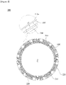
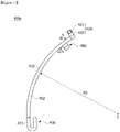
- FIG. 1 is a view illustrating a motor according to an embodiment
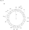
- FIG. 2 is an exploded perspective illustrating coupling of a stator and a power terminal according to the embodiment.
- a motor 1 includes a rotor 100, a stator 200, a shaft 300, and a plurality of terminals 400. Further, the motor 1 may also include a housing 500 to fix the terminal 400 installed on the stator 200.
- the terminal 400 is provided as a power terminal configured to apply power to a coil, and hereinafter, the terminal 400 is described as power terminal 400.
- the rotor 100 is disposed inside the stator 200.
- the rotor 100 is configured by coupling of a magnet 120 to a rotor core 110.
- the rotor 100 may be configured by inserting the magnet into a pocket provided in the rotor core 110.
- a sensing magnet configured to gain location information of the rotor 100 may be coupled to a plate and installed on the rotor 100, or a rotor location sensing means may be installed on the rotor 100.
- both ends of the shaft 300 may be rotatably supported by a bearing.
- the stator 200 is coupled to the housing 500, and the rotor 100 is disposed at the inside of the stator 200.
- the shaft 300 may be coupled to a center portion of the rotor 100.
- the coil is wound around the stator 200, and thus the stator 200 has a magnetic pole.
- the rotor 100 rotates due to a magnetic field formed by winding of the coil, and the shaft 300 rotates at the same time.
- the stator 200 may include a stator core 210, an insulator 220 disposed in the stator core 210, and a coil 230 wound around the insulator 220.
- the stator core 210 may include a main body 211 having a cylindrical shape and a plurality of teeth 212 formed to protrude in a radial direction along a circumferential direction of the main body 211 with respect to a virtual line which passes through a center C of the main body 211.
- the tooth 212 may include a first tooth 212a of which a cross-section has a T shape and a second tooth 212b of which a cross-section has an 1 shape.
- each of the first tooth 212a and the second tooth 212b may be disposed in the main body 211 to have a predetermined outer radius R1 with respect to a center C of the stator core 210.
- a width W1 of the first tooth 212a may be formed to be greater than a width W2 of the second tooth 212b. That is, since widths of the first tooth 212a and the second tooth 212b are different, a winding amount of the coil 230 wound around the first tooth 212a and a spaced distance between the first teeth 212a may be adjusted. Accordingly, a change of the magnetic field may be induced.
- the second tooth 212b may prevent contact between the coils 230 which are each wound around each of the first teeth 212a.
- the second tooth 212b may prevent the contact between the coils 230 e which are ach wound around each of the first teeth 212a.
- stator core 210 may be formed by stacking thin plate-shaped stator plates so that the plurality of teeth 212 may be formed to protrude in the radial direction.
- stator plates may be stacked to form the stator core 210.
- stator core 210 may be manufactured as a skew-type.
- the tooth 212 may be provided as the first tooth 212a having a T shape twisted at a predetermined angle and the second tooth 212b having an 1 shape twisted at the predetermined angle.
- the present invention is not limited thereto, and only one of the first tooth 212a and the second tooth 212b may be formed as the skew-type or only one of the first tooth 212a and the second tooth 212b may be disposed in the main body 211 as the skew-type.
- cogging torque of the stator core 210 formed in the skew-type may be minimized, and accordingly, noises and vibrations may be greatly reduced.
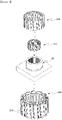
- the insulator 220 may be located at one area of the stator core 210 using an insert injection-molding method.
- the insulator 220 may be formed on an upper part, a lower part, and a side surface of the tooth 212. Accordingly, the tooth 212 may be insulated from the coil 230 by the insulator 220.
- the stator core 210 in which the plurality of teeth 212 are formed may be disposed in the mold 10, and the insulator 220 may be formed through the insert injection-molding method.
- the insulator 220 may be made of one material among resin, synthetic resins, rubber, and urethane and may also be injection-molded with a plurality of terminal members.
- stator core 210 since the stator core 210 is formed as the skew-type, the stator core 210 may be disposed in the mold 10 while rotating at a predetermined angle.
- an outer radius R2 of the insulator 220 formed through the insert injection-molding method may be formed to be smaller than the outer radius R1 of the tooth 212. Accordingly, a gap d may be formed between the tooth 212 and the insulator 220.
- the outer radius R1 of the tooth 212 may refer to a distance from the center C to an outer circumferential surface 213 of the tooth 212
- the outer radius R2 of the insulator 220 may refer to a distance from the center C to an outer circumferential surface 221 of the insulator 220.
- the gap d may be formed on each of the first tooth 212a and the second tooth 212b, and the gap d formed on the first tooth 212a is described with reference to FIGS. 6 to 9 .
- the insulator 220 may be formed by inserting resin or the like thereinto so that the gap d may be formed between the first tooth 212a and the insulator 220.
- the resin or the like when the resin or the like is inserted so that the outer radius R1 of the tooth 212 and the outer radius R2 of the insulator 220 are the same, since the resin or the like flows to the outer circumferential surface of the tooth 212 due to a gap between the mold 10 and the outer radius R1 of the tooth 212 and thus an unnecessary injection-molding product may be formed, in the embodiment, the resin or the like may be inserted to form the gap d.
- the gap d may be formed on the upper part and the lower part of the tooth 212. As shown in FIG. 8 , the gap d may be formed on an upper surface and a lower surface of the tooth 212.
- a structure of the mold 10 may be simplified, and generation of the unnecessary injection-molding product may be minimized.
- the outer radius R2 of the insulator 220 disposed on the side surface of the tooth 212 and the outer radius R1 of the tooth 212 may be even, and thus the unnecessary injection-molding product may be generated slightly.
- the gap d may be formed on the upper part and the lower part of the tooth 212 to minimize forming of the unnecessary injection-molding product.
- the gap d may be formed on not only the upper part and the lower part of the tooth 212 but also on the side surface 214 of the tooth 212.
- the structure of the mold 10 may be complicated, generation of an unnecessary injection-molding product formed on the outer circumferential surface 213 may be fundamentally prevented.
- the stator core 210 may be formed through the above-described stacking method. That is, the stator core 210 in which a skew is formed by a bonded stacking method may be formed, and the insulator 220 may be injection-molded in the stator core 210 in which the skew is formed to form the stator 200.
- the plurality of power terminals 400 disposed to apply power (not shown) to the coil 230 may be disposed on the insulator 220.
- the power terminal 400 includes a body 410, a pin portion 420, a coupling portion 430, and a first protrusion 440. Further, the power terminal 400 also includes a second protrusion 450.
- the body 410 may be formed to be curved toward to the outside to have a predetermined curvature radius R3.
- the body 410 may be formed in an arc shape.
- the body 410 may be disposed on the insulator 220 along the circumferential direction with respect to the center C.
- the pin portion 420 is formed to protrude upward from the body 410 and may be integrally formed with the body 410. That is, the pin portion 420 is formed to extend upward from one side of the body 410.
- the pin portion 420 includes a power connection part 421 disposed to be spaced apart from the body 410 and a first connection part 422 disposed between the body 410 and the power connection part 421.
- the power connection part 421 and the first connection part 422 may be integrally formed, and an end of the power connection part 421 may be formed in a cylindrical shape.
- the power connection part 421 may be formed in a triangular prism shape, a quadrangular pillar shape, or a polygonal pillar shape in consideration of electrical connection with the power.
- the pin portion 420 is disposed to be spaced apart toward the outside from an outer circumferential surface 411 of the body 410.
- the outside refers to an outside in the radial direction of the center C with respect to the body 410
- an inside refers to the inside in the radial direction of the center C with respect to the body 410.
- the pin portion 420 of the embodiment is disposed to be spaced apart toward the outside from the body 410. However, in a disposition relation between the pin portion 420 and the second protrusion 450, the pin portion 420 and the second protrusion 450 are disposed to be oppositely spaced apart from each other with respect to the body 410 for structural stability.
- the coupling portion 430 may be formed on one end of the body 410 to be coupled to an end of the coil 230. Further, the coupling portion 430 may be integrally formed with the body 410.
- the coupling portion 430 may be formed in a structure which comes into contact with, and is coupled to, the end of the coil 230.
- the coupling portion 430 may be formed to be bent in a shape which surrounds the end of the coil 230. That is, as shown in FIG. 2 , the coupling portion 430 may have a cross-section formed in a U shape. In this case, the coupling portion 430 may be formed by inwardly bending the one end of body 410.
- the coupling portion 430 may be formed to have a predetermined height difference h from the body 410.
- an upper surface 431 of the coupling portion 430 may be disposed to be higher than an upper surface 413 of the body 410. That is, as shown in FIGS. 12 , 15 , and 18, a height h1 of the coupling portion 430 may be disposed to be greater than a height h2 of the body 410 with respect to a lower surface 414 of the body 410.
- the end of the coil 230 may be easily coupled to the coupling portion 430.
- the first protrusion 440 and the second protrusion 450 are formed to protrude downward from the body 410.
- the first protrusion 440 and the second protrusion 450 are integrally formed with the body 410.
- first protrusion 440 and the second protrusion 450 are insertion-coupled to an insertion port 222 formed in the insulator 220.
- the second protrusion 450 is disposed to be spaced apart toward the inside from the body 410. As shown in FIGS. 11 and 14 , the second protrusion 450 are disposed to be spaced apart toward the inside from an inner circumferential surface 412 of the body 410.
- the second protrusion 450 may include a fitting part 451 disposed to be spaced apart from the body 410 and a second connection part 452 disposed between the body 410 and the fitting part 451.
- the second protrusion 450 is disposed to be spaced apart from the first protrusion 440 along a circumferential direction and is also disposed to be spaced apart from the body 410, vibrations and movement of the power terminal 400 in the circumferential direction or the radial direction are prevented. Accordingly, noise generation according to the vibrations of the power terminal 400 due to rotation of the motor 1 is prevented.
- the power terminal 400 may be formed in a various shapes.
- the power terminal 400 is classified into a first power terminal 400a, a second power terminal 400b, and a third power terminal 400c, which are embodiments thereof, to clarify a description of the various embodiments of the power terminal 400.
- the power terminal 400 disposed on the insulator 220 may be numerously disposed due to at least of one or a combination of the first power terminal 400a, the second power terminal 400b, and the third power terminal 400c.
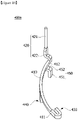
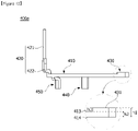
- FIG. 10 is a perspective view illustrating the first power terminal 400a according to the embodiment.
- FIG. 11 is a plan view illustrating the first power terminal 400a according to the embodiment.
- FIG. 12 is a side view in which the first power terminal 400a according to the embodiment is viewed from the radial direction.
- the pin portion 420 of the first power terminal 400a may be disposed on one end of the body 410.
- the coupling portion 430 may be disposed on the other end of the body 410.
- the coupling portion 430 may be formed by inwardly bending the one end of the body 410. Accordingly, the coupling portion 430 may be formed in a U shape from a top view.
- the height h1 of the coupling portion 430 may be disposed to be greater than the height h2 of the body 410 with respect to the lower surface 414 of the body 410.
- the pin portion 420 is disposed to be outwardly spaced apart from the outer circumferential surface 411 of the body 410 by a predetermined interval d1
- the second protrusion 450 is disposed to be inwardly spaced apart from the inner circumferential surface 412 of the body 410 at a predetermined interval d2.
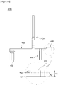
- FIG. 13 is a perspective view illustrating the second power terminal 400b according to another embodiment.
- FIG. 14 is a plan view illustrating the second power terminal 400b according to another embodiment.
- FIG. 15 is a side view in which the second power terminal 400b according to another embodiment is viewed from a radial direction.
- a coupling portion 430 of the second power terminal 400b may be disposed on one end of a body 410. Further, a pin portion 420 may be disposed between the one end and the other end of the body 410. In addition, a second protrusion 450 may be disposed on the other end of the body 410.
- the coupling portion 430 may be formed by inwardly bending the one end of the body 410. Accordingly, the coupling portion 430 may be formed in a U shape from a top view.
- a height h1 of the coupling portion 430 may be disposed to be greater than a height h2 of the body 410 with respect to a lower surface 414 of the body 410.
- the pin portion 420 is disposed to be outwardly spaced apart from an outer circumferential surface 411 of the body 410 at a predetermined interval d1
- the second protrusion 450 is disposed to be inwardly spaced apart from an inner circumferential surface 412 of the body 410 at a predetermined interval d2.
- the power terminal 400 may be disposed without limitation of a location, in which the end 231 of the coil 230 is exposed, to be coupled to the end of the coil 230.
- the housing 500 is disposed so that the power terminal 400 may be fixed to the stator 200.
- the housing 500 may include a cylindrical-shaped housing main body 510 and a flange 520 formed to protrude outward from an end of the housing main body 510.
- the housing main body 510 and the flange 520 may be integrally formed.
- the housing main body 510 may be disposed at the outside of the stator 200 to surround an outer circumferential surface of the stator 200.
- the flange 520 may be disposed on the stator 200 to press an upper part of the power terminal 400.
- the pin portion 420 of the power terminal 400 may be disposed to pass through the flange 520.
- a through hole 521 may be formed in the flange 520 to allow the pin portion 420 to pass therethrough and be coupled thereto.
- coupling of the pin portion 420 and the through hole 521 limits an assembly location of the housing 500 when the housing 500 is assembled.
- the housing 500 prevents the noise generation by preventing the vibrations of the power terminal 400 due to the rotation of the motor 1.
- the pin portion 420, the first protrusion 440, and the second protrusion 450 of the power terminal 400 are integrally formed with the body 410, and thus may be manufactured in one mold. Accordingly, a structure of the power terminal 400 may be simplified, and thus manufacturing and an assembly process of the power terminal 400 may be simplified.
- the power terminal 400 may satisfy true position geometric tolerance and improve size precision to increase the yield.
- the pin portion 420, the first protrusion 440, and the second protrusion 450 of the power terminal 400 may implement a three-dimensional three point support structure which is coupled to the insulator 220 and the housing 500 to prevent the generation of the vibrations and noises according to the rotation of the motor 1 and secure the structural stability.
Landscapes
- Engineering & Computer Science (AREA)
- Power Engineering (AREA)
- Insulation, Fastening Of Motor, Generator Windings (AREA)
- Motor Or Generator Frames (AREA)
- Iron Core Of Rotating Electric Machines (AREA)
- Windings For Motors And Generators (AREA)
Applications Claiming Priority (2)
| Application Number | Priority Date | Filing Date | Title |
|---|---|---|---|
| KR1020160051508A KR102697649B1 (ko) | 2016-04-27 | 2016-04-27 | 파워 터미널 및 이를 포함하는 모터 |
| PCT/KR2017/004221 WO2017188659A1 (ko) | 2016-04-27 | 2017-04-20 | 파워 터미널 및 이를 포함하는 모터 |
Publications (3)
| Publication Number | Publication Date |
|---|---|
| EP3451508A1 EP3451508A1 (en) | 2019-03-06 |
| EP3451508A4 EP3451508A4 (en) | 2019-12-25 |
| EP3451508B1 true EP3451508B1 (en) | 2023-01-18 |
Family
ID=60159870
Family Applications (1)
| Application Number | Title | Priority Date | Filing Date |
|---|---|---|---|
| EP17789844.2A Active EP3451508B1 (en) | 2016-04-27 | 2017-04-20 | Power terminal and motor including same |
Country Status (6)
| Country | Link |
|---|---|
| US (1) | US11152824B2 (enExample) |
| EP (1) | EP3451508B1 (enExample) |
| JP (1) | JP6991998B2 (enExample) |
| KR (1) | KR102697649B1 (enExample) |
| CN (1) | CN109075654B (enExample) |
| WO (1) | WO2017188659A1 (enExample) |
Families Citing this family (10)
| Publication number | Priority date | Publication date | Assignee | Title |
|---|---|---|---|---|
| US11196316B2 (en) * | 2017-03-31 | 2021-12-07 | Nidec Corporation | Motor and electric power steering apparatus |
| KR102547568B1 (ko) * | 2017-12-04 | 2023-06-26 | 엘지이노텍 주식회사 | 모터 |
| KR102656510B1 (ko) * | 2018-12-11 | 2024-04-12 | 엘지이노텍 주식회사 | 모터 |
| KR102740563B1 (ko) * | 2018-12-26 | 2024-12-11 | 엘지이노텍 주식회사 | 모터 |
| DE102020100963B4 (de) * | 2020-01-16 | 2024-03-28 | Audi Aktiengesellschaft | Elektrische Maschine und Kraftfahrzeug |
| JP7613116B2 (ja) * | 2021-01-13 | 2025-01-15 | 株式会社デンソー | ステータ及び回転電機 |
| KR102812228B1 (ko) * | 2021-01-25 | 2025-05-26 | 항저우 아오 케 메이 뤼 테크놀로지 컴퍼니 리미티드 | 유체 구동 장치 |
| EP4037158B1 (en) | 2021-02-02 | 2025-07-30 | Black & Decker, Inc. | Brushless motor including a nested bearing bridge |
| US20240429767A1 (en) * | 2021-11-08 | 2024-12-26 | Lg Innotek Co., Ltd. | Motor |
| KR102890457B1 (ko) * | 2023-12-29 | 2025-11-27 | 주식회사 엔엠씨 | 스테이터에 배치된 감속체를 포함하는 축방향 자속형 모터 |
Family Cites Families (17)
| Publication number | Priority date | Publication date | Assignee | Title |
|---|---|---|---|---|
| JPS6192134A (ja) | 1984-10-11 | 1986-05-10 | Matsushita Electric Ind Co Ltd | 電動機 |
| JP2802082B2 (ja) | 1988-10-28 | 1998-09-21 | 松下精工株式会社 | 電動機の固定子鉄心 |
| JP2583638Y2 (ja) | 1992-05-15 | 1998-10-27 | 日本精工株式会社 | インナーロータ型ブラシレスモータ |
| JP3791492B2 (ja) | 2002-12-25 | 2006-06-28 | 株式会社日立製作所 | 回転電機及び電動車両並びに樹脂のインサート成形方法 |
| JP2004336966A (ja) * | 2003-05-12 | 2004-11-25 | Mitsubishi Electric Corp | 回転電機 |
| JP2007318885A (ja) * | 2006-05-25 | 2007-12-06 | Mabuchi Motor Co Ltd | ブラシレスモータ |
| WO2009025144A1 (ja) * | 2007-08-17 | 2009-02-26 | Kabushiki Kaisha Yaskawa Denki | 固定子およびこれを用いた回転電機 |
| KR101173757B1 (ko) * | 2010-06-30 | 2012-08-13 | 뉴모텍(주) | 인쇄회로기판을 이용한 스테이터 코어의 코일의 결선 구조 |
| JP2012196018A (ja) | 2011-03-15 | 2012-10-11 | Toyota Auto Body Co Ltd | 三相モータの配線構造 |
| JP2013042633A (ja) | 2011-08-19 | 2013-02-28 | Nippon Densan Corp | モータ |
| JP5801216B2 (ja) * | 2012-02-06 | 2015-10-28 | 愛三工業株式会社 | モータ及び電動ポンプ |
| US20140028127A1 (en) * | 2012-07-25 | 2014-01-30 | Bradley Duane Chamberlin | Buss bar assembly having alignment and retention feature |
| JP2014093807A (ja) * | 2012-11-01 | 2014-05-19 | Aisan Ind Co Ltd | ステータ用端子 |
| JP6190599B2 (ja) * | 2013-03-08 | 2017-08-30 | Kyb株式会社 | バスバーユニットの製造方法 |
| JP6286129B2 (ja) * | 2013-03-08 | 2018-02-28 | Kyb株式会社 | バスバーユニット |
| JP6267907B2 (ja) * | 2013-09-26 | 2018-01-24 | 株式会社ミツバ | バスバーユニットおよびブラシレスモータ |
| JP6353723B2 (ja) * | 2014-07-10 | 2018-07-04 | Kyb株式会社 | バスバーユニット、これを備えた回転電機及びバスバーユニットの製造方法 |
-
2016
- 2016-04-27 KR KR1020160051508A patent/KR102697649B1/ko active Active
-
2017
- 2017-04-20 CN CN201780026246.8A patent/CN109075654B/zh active Active
- 2017-04-20 EP EP17789844.2A patent/EP3451508B1/en active Active
- 2017-04-20 WO PCT/KR2017/004221 patent/WO2017188659A1/ko not_active Ceased
- 2017-04-20 JP JP2018554465A patent/JP6991998B2/ja active Active
- 2017-04-20 US US16/096,567 patent/US11152824B2/en active Active
Also Published As
| Publication number | Publication date |
|---|---|
| WO2017188659A1 (ko) | 2017-11-02 |
| EP3451508A1 (en) | 2019-03-06 |
| CN109075654A (zh) | 2018-12-21 |
| JP6991998B2 (ja) | 2022-01-13 |
| KR20170122486A (ko) | 2017-11-06 |
| EP3451508A4 (en) | 2019-12-25 |
| US11152824B2 (en) | 2021-10-19 |
| JP2019516336A (ja) | 2019-06-13 |
| US20190140496A1 (en) | 2019-05-09 |
| CN109075654B (zh) | 2021-01-26 |
| KR102697649B1 (ko) | 2024-08-23 |
Similar Documents
| Publication | Publication Date | Title |
|---|---|---|
| EP3451508B1 (en) | Power terminal and motor including same | |
| US9000629B2 (en) | Stator segment and motor | |
| US9160217B2 (en) | Busbar unit and motor | |
| US11258321B2 (en) | Motor having rotor frame with magnet fixing jig holes | |
| EP3193428B1 (en) | Stator | |
| US20120286593A1 (en) | Stator and motor | |
| EP2947754B1 (en) | Electric motor, pump device using electric motor, and stator | |
| CN101494399A (zh) | 马达及具备该马达的马达一体型泵 | |
| CN109923765B (zh) | 盖组件和包括该盖组件的马达 | |
| EP4071973B1 (en) | Axial gap motor | |
| KR102809327B1 (ko) | 모터 및 스테이터 조립체 | |
| CN114902531A (zh) | 马达 | |
| WO2020067250A1 (ja) | ステータ、モータおよびステータの製造方法 | |
| JP2019054622A (ja) | ステータ、モータ、およびステータの製造方法 | |
| EP4203255A1 (en) | Motor with bidirectional terminals | |
| KR20210112753A (ko) | 로터 및 이를 포함하는 모터 | |
| US12362623B2 (en) | Cover and motor comprising same | |
| US12368342B2 (en) | Motor | |
| EP4318882A1 (en) | Motor | |
| US12294278B2 (en) | Motor | |
| KR20200064531A (ko) | 모터 | |
| KR102570251B1 (ko) | 스테이터 및 이를 포함하는 모터 | |
| KR20230083621A (ko) | 모터 | |
| KR102809429B1 (ko) | 로터 및 이를 포함하는 모터 | |
| KR102796036B1 (ko) | 모터 |
Legal Events
| Date | Code | Title | Description |
|---|---|---|---|
| STAA | Information on the status of an ep patent application or granted ep patent |
Free format text: STATUS: THE INTERNATIONAL PUBLICATION HAS BEEN MADE |
|
| PUAI | Public reference made under article 153(3) epc to a published international application that has entered the european phase |
Free format text: ORIGINAL CODE: 0009012 |
|
| STAA | Information on the status of an ep patent application or granted ep patent |
Free format text: STATUS: REQUEST FOR EXAMINATION WAS MADE |
|
| 17P | Request for examination filed |
Effective date: 20181010 |
|
| AK | Designated contracting states |
Kind code of ref document: A1 Designated state(s): AL AT BE BG CH CY CZ DE DK EE ES FI FR GB GR HR HU IE IS IT LI LT LU LV MC MK MT NL NO PL PT RO RS SE SI SK SM TR |
|
| AX | Request for extension of the european patent |
Extension state: BA ME |
|
| DAV | Request for validation of the european patent (deleted) | ||
| DAX | Request for extension of the european patent (deleted) | ||
| A4 | Supplementary search report drawn up and despatched |
Effective date: 20191121 |
|
| RIC1 | Information provided on ipc code assigned before grant |
Ipc: H02K 3/52 20060101ALI20191115BHEP Ipc: H02K 5/22 20060101AFI20191115BHEP Ipc: H02K 3/34 20060101ALI20191115BHEP Ipc: H02K 1/16 20060101ALN20191115BHEP Ipc: H02K 1/24 20060101ALI20191115BHEP |
|
| STAA | Information on the status of an ep patent application or granted ep patent |
Free format text: STATUS: EXAMINATION IS IN PROGRESS |
|
| 17Q | First examination report despatched |
Effective date: 20201207 |
|
| GRAP | Despatch of communication of intention to grant a patent |
Free format text: ORIGINAL CODE: EPIDOSNIGR1 |
|
| STAA | Information on the status of an ep patent application or granted ep patent |
Free format text: STATUS: GRANT OF PATENT IS INTENDED |
|
| RIC1 | Information provided on ipc code assigned before grant |
Ipc: H02K 1/16 20060101ALN20220831BHEP Ipc: H02K 3/52 20060101ALI20220831BHEP Ipc: H02K 3/34 20060101ALI20220831BHEP Ipc: H02K 1/24 20060101ALI20220831BHEP Ipc: H02K 5/22 20060101AFI20220831BHEP |
|
| INTG | Intention to grant announced |
Effective date: 20220926 |
|
| GRAS | Grant fee paid |
Free format text: ORIGINAL CODE: EPIDOSNIGR3 |
|
| GRAA | (expected) grant |
Free format text: ORIGINAL CODE: 0009210 |
|
| STAA | Information on the status of an ep patent application or granted ep patent |
Free format text: STATUS: THE PATENT HAS BEEN GRANTED |
|
| AK | Designated contracting states |
Kind code of ref document: B1 Designated state(s): AL AT BE BG CH CY CZ DE DK EE ES FI FR GB GR HR HU IE IS IT LI LT LU LV MC MK MT NL NO PL PT RO RS SE SI SK SM TR |
|
| REG | Reference to a national code |
Ref country code: GB Ref legal event code: FG4D |
|
| REG | Reference to a national code |
Ref country code: DE Ref legal event code: R096 Ref document number: 602017065601 Country of ref document: DE |
|
| REG | Reference to a national code |
Ref country code: CH Ref legal event code: EP |
|
| REG | Reference to a national code |
Ref country code: AT Ref legal event code: REF Ref document number: 1545215 Country of ref document: AT Kind code of ref document: T Effective date: 20230215 Ref country code: IE Ref legal event code: FG4D |
|
| REG | Reference to a national code |
Ref country code: LT Ref legal event code: MG9D |
|
| REG | Reference to a national code |
Ref country code: NL Ref legal event code: MP Effective date: 20230118 |
|
| REG | Reference to a national code |
Ref country code: AT Ref legal event code: MK05 Ref document number: 1545215 Country of ref document: AT Kind code of ref document: T Effective date: 20230118 |
|
| PG25 | Lapsed in a contracting state [announced via postgrant information from national office to epo] |
Ref country code: NL Free format text: LAPSE BECAUSE OF FAILURE TO SUBMIT A TRANSLATION OF THE DESCRIPTION OR TO PAY THE FEE WITHIN THE PRESCRIBED TIME-LIMIT Effective date: 20230118 |
|
| PG25 | Lapsed in a contracting state [announced via postgrant information from national office to epo] |
Ref country code: RS Free format text: LAPSE BECAUSE OF FAILURE TO SUBMIT A TRANSLATION OF THE DESCRIPTION OR TO PAY THE FEE WITHIN THE PRESCRIBED TIME-LIMIT Effective date: 20230118 Ref country code: PT Free format text: LAPSE BECAUSE OF FAILURE TO SUBMIT A TRANSLATION OF THE DESCRIPTION OR TO PAY THE FEE WITHIN THE PRESCRIBED TIME-LIMIT Effective date: 20230518 Ref country code: NO Free format text: LAPSE BECAUSE OF FAILURE TO SUBMIT A TRANSLATION OF THE DESCRIPTION OR TO PAY THE FEE WITHIN THE PRESCRIBED TIME-LIMIT Effective date: 20230418 Ref country code: LV Free format text: LAPSE BECAUSE OF FAILURE TO SUBMIT A TRANSLATION OF THE DESCRIPTION OR TO PAY THE FEE WITHIN THE PRESCRIBED TIME-LIMIT Effective date: 20230118 Ref country code: LT Free format text: LAPSE BECAUSE OF FAILURE TO SUBMIT A TRANSLATION OF THE DESCRIPTION OR TO PAY THE FEE WITHIN THE PRESCRIBED TIME-LIMIT Effective date: 20230118 Ref country code: HR Free format text: LAPSE BECAUSE OF FAILURE TO SUBMIT A TRANSLATION OF THE DESCRIPTION OR TO PAY THE FEE WITHIN THE PRESCRIBED TIME-LIMIT Effective date: 20230118 Ref country code: ES Free format text: LAPSE BECAUSE OF FAILURE TO SUBMIT A TRANSLATION OF THE DESCRIPTION OR TO PAY THE FEE WITHIN THE PRESCRIBED TIME-LIMIT Effective date: 20230118 Ref country code: AT Free format text: LAPSE BECAUSE OF FAILURE TO SUBMIT A TRANSLATION OF THE DESCRIPTION OR TO PAY THE FEE WITHIN THE PRESCRIBED TIME-LIMIT Effective date: 20230118 |
|
| PG25 | Lapsed in a contracting state [announced via postgrant information from national office to epo] |
Ref country code: SE Free format text: LAPSE BECAUSE OF FAILURE TO SUBMIT A TRANSLATION OF THE DESCRIPTION OR TO PAY THE FEE WITHIN THE PRESCRIBED TIME-LIMIT Effective date: 20230118 Ref country code: PL Free format text: LAPSE BECAUSE OF FAILURE TO SUBMIT A TRANSLATION OF THE DESCRIPTION OR TO PAY THE FEE WITHIN THE PRESCRIBED TIME-LIMIT Effective date: 20230118 Ref country code: IS Free format text: LAPSE BECAUSE OF FAILURE TO SUBMIT A TRANSLATION OF THE DESCRIPTION OR TO PAY THE FEE WITHIN THE PRESCRIBED TIME-LIMIT Effective date: 20230518 Ref country code: GR Free format text: LAPSE BECAUSE OF FAILURE TO SUBMIT A TRANSLATION OF THE DESCRIPTION OR TO PAY THE FEE WITHIN THE PRESCRIBED TIME-LIMIT Effective date: 20230419 Ref country code: FI Free format text: LAPSE BECAUSE OF FAILURE TO SUBMIT A TRANSLATION OF THE DESCRIPTION OR TO PAY THE FEE WITHIN THE PRESCRIBED TIME-LIMIT Effective date: 20230118 |
|
| REG | Reference to a national code |
Ref country code: DE Ref legal event code: R097 Ref document number: 602017065601 Country of ref document: DE |
|
| PG25 | Lapsed in a contracting state [announced via postgrant information from national office to epo] |
Ref country code: SM Free format text: LAPSE BECAUSE OF FAILURE TO SUBMIT A TRANSLATION OF THE DESCRIPTION OR TO PAY THE FEE WITHIN THE PRESCRIBED TIME-LIMIT Effective date: 20230118 Ref country code: RO Free format text: LAPSE BECAUSE OF FAILURE TO SUBMIT A TRANSLATION OF THE DESCRIPTION OR TO PAY THE FEE WITHIN THE PRESCRIBED TIME-LIMIT Effective date: 20230118 Ref country code: EE Free format text: LAPSE BECAUSE OF FAILURE TO SUBMIT A TRANSLATION OF THE DESCRIPTION OR TO PAY THE FEE WITHIN THE PRESCRIBED TIME-LIMIT Effective date: 20230118 Ref country code: DK Free format text: LAPSE BECAUSE OF FAILURE TO SUBMIT A TRANSLATION OF THE DESCRIPTION OR TO PAY THE FEE WITHIN THE PRESCRIBED TIME-LIMIT Effective date: 20230118 Ref country code: CZ Free format text: LAPSE BECAUSE OF FAILURE TO SUBMIT A TRANSLATION OF THE DESCRIPTION OR TO PAY THE FEE WITHIN THE PRESCRIBED TIME-LIMIT Effective date: 20230118 |
|
| PLBE | No opposition filed within time limit |
Free format text: ORIGINAL CODE: 0009261 |
|
| STAA | Information on the status of an ep patent application or granted ep patent |
Free format text: STATUS: NO OPPOSITION FILED WITHIN TIME LIMIT |
|
| PG25 | Lapsed in a contracting state [announced via postgrant information from national office to epo] |
Ref country code: SK Free format text: LAPSE BECAUSE OF FAILURE TO SUBMIT A TRANSLATION OF THE DESCRIPTION OR TO PAY THE FEE WITHIN THE PRESCRIBED TIME-LIMIT Effective date: 20230118 |
|
| REG | Reference to a national code |
Ref country code: CH Ref legal event code: PL |
|
| 26N | No opposition filed |
Effective date: 20231019 |
|
| GBPC | Gb: european patent ceased through non-payment of renewal fee |
Effective date: 20230420 |
|
| PG25 | Lapsed in a contracting state [announced via postgrant information from national office to epo] |
Ref country code: LU Free format text: LAPSE BECAUSE OF NON-PAYMENT OF DUE FEES Effective date: 20230420 |
|
| REG | Reference to a national code |
Ref country code: BE Ref legal event code: MM Effective date: 20230430 |
|
| PG25 | Lapsed in a contracting state [announced via postgrant information from national office to epo] |
Ref country code: MC Free format text: LAPSE BECAUSE OF FAILURE TO SUBMIT A TRANSLATION OF THE DESCRIPTION OR TO PAY THE FEE WITHIN THE PRESCRIBED TIME-LIMIT Effective date: 20230118 |
|
| PG25 | Lapsed in a contracting state [announced via postgrant information from national office to epo] |
Ref country code: GB Free format text: LAPSE BECAUSE OF NON-PAYMENT OF DUE FEES Effective date: 20230420 |
|
| PG25 | Lapsed in a contracting state [announced via postgrant information from national office to epo] |
Ref country code: SI Free format text: LAPSE BECAUSE OF FAILURE TO SUBMIT A TRANSLATION OF THE DESCRIPTION OR TO PAY THE FEE WITHIN THE PRESCRIBED TIME-LIMIT Effective date: 20230118 Ref country code: MC Free format text: LAPSE BECAUSE OF FAILURE TO SUBMIT A TRANSLATION OF THE DESCRIPTION OR TO PAY THE FEE WITHIN THE PRESCRIBED TIME-LIMIT Effective date: 20230118 Ref country code: LI Free format text: LAPSE BECAUSE OF NON-PAYMENT OF DUE FEES Effective date: 20230430 Ref country code: GB Free format text: LAPSE BECAUSE OF NON-PAYMENT OF DUE FEES Effective date: 20230420 Ref country code: CH Free format text: LAPSE BECAUSE OF NON-PAYMENT OF DUE FEES Effective date: 20230430 |
|
| REG | Reference to a national code |
Ref country code: IE Ref legal event code: MM4A |
|
| PG25 | Lapsed in a contracting state [announced via postgrant information from national office to epo] |
Ref country code: BE Free format text: LAPSE BECAUSE OF NON-PAYMENT OF DUE FEES Effective date: 20230430 |
|
| PG25 | Lapsed in a contracting state [announced via postgrant information from national office to epo] |
Ref country code: IE Free format text: LAPSE BECAUSE OF NON-PAYMENT OF DUE FEES Effective date: 20230420 |
|
| PG25 | Lapsed in a contracting state [announced via postgrant information from national office to epo] |
Ref country code: IE Free format text: LAPSE BECAUSE OF NON-PAYMENT OF DUE FEES Effective date: 20230420 |
|
| PG25 | Lapsed in a contracting state [announced via postgrant information from national office to epo] |
Ref country code: IT Free format text: LAPSE BECAUSE OF FAILURE TO SUBMIT A TRANSLATION OF THE DESCRIPTION OR TO PAY THE FEE WITHIN THE PRESCRIBED TIME-LIMIT Effective date: 20230118 |
|
| PG25 | Lapsed in a contracting state [announced via postgrant information from national office to epo] |
Ref country code: BG Free format text: LAPSE BECAUSE OF FAILURE TO SUBMIT A TRANSLATION OF THE DESCRIPTION OR TO PAY THE FEE WITHIN THE PRESCRIBED TIME-LIMIT Effective date: 20230118 |
|
| PG25 | Lapsed in a contracting state [announced via postgrant information from national office to epo] |
Ref country code: BG Free format text: LAPSE BECAUSE OF FAILURE TO SUBMIT A TRANSLATION OF THE DESCRIPTION OR TO PAY THE FEE WITHIN THE PRESCRIBED TIME-LIMIT Effective date: 20230118 |
|
| PGFP | Annual fee paid to national office [announced via postgrant information from national office to epo] |
Ref country code: FR Payment date: 20250321 Year of fee payment: 9 |
|
| PGFP | Annual fee paid to national office [announced via postgrant information from national office to epo] |
Ref country code: DE Payment date: 20250320 Year of fee payment: 9 |
|
| PG25 | Lapsed in a contracting state [announced via postgrant information from national office to epo] |
Ref country code: CY Free format text: LAPSE BECAUSE OF FAILURE TO SUBMIT A TRANSLATION OF THE DESCRIPTION OR TO PAY THE FEE WITHIN THE PRESCRIBED TIME-LIMIT; INVALID AB INITIO Effective date: 20170420 |
|
| PG25 | Lapsed in a contracting state [announced via postgrant information from national office to epo] |
Ref country code: HU Free format text: LAPSE BECAUSE OF FAILURE TO SUBMIT A TRANSLATION OF THE DESCRIPTION OR TO PAY THE FEE WITHIN THE PRESCRIBED TIME-LIMIT; INVALID AB INITIO Effective date: 20170420 |
|
| PG25 | Lapsed in a contracting state [announced via postgrant information from national office to epo] |
Ref country code: TR Free format text: LAPSE BECAUSE OF FAILURE TO SUBMIT A TRANSLATION OF THE DESCRIPTION OR TO PAY THE FEE WITHIN THE PRESCRIBED TIME-LIMIT Effective date: 20230118 |