EP3450834A1 - Beleuchtungs- und/oder signalisierungsvorrichtung für ein kraftfahrzeug - Google Patents
Beleuchtungs- und/oder signalisierungsvorrichtung für ein kraftfahrzeug Download PDFInfo
- Publication number
- EP3450834A1 EP3450834A1 EP18186236.8A EP18186236A EP3450834A1 EP 3450834 A1 EP3450834 A1 EP 3450834A1 EP 18186236 A EP18186236 A EP 18186236A EP 3450834 A1 EP3450834 A1 EP 3450834A1
- Authority
- EP
- European Patent Office
- Prior art keywords
- light
- light guide
- optical fiber
- optical
- windows
- Prior art date
- Legal status (The legal status is an assumption and is not a legal conclusion. Google has not performed a legal analysis and makes no representation as to the accuracy of the status listed.)
- Granted
Links
Images


Classifications
-
- F—MECHANICAL ENGINEERING; LIGHTING; HEATING; WEAPONS; BLASTING
- F21—LIGHTING
- F21S—NON-PORTABLE LIGHTING DEVICES; SYSTEMS THEREOF; VEHICLE LIGHTING DEVICES SPECIALLY ADAPTED FOR VEHICLE EXTERIORS
- F21S43/00—Signalling devices specially adapted for vehicle exteriors, e.g. brake lamps, direction indicator lights or reversing lights
- F21S43/20—Signalling devices specially adapted for vehicle exteriors, e.g. brake lamps, direction indicator lights or reversing lights characterised by refractors, transparent cover plates, light guides or filters
- F21S43/235—Light guides
- F21S43/236—Light guides characterised by the shape of the light guide
- F21S43/237—Light guides characterised by the shape of the light guide rod-shaped
-
- F—MECHANICAL ENGINEERING; LIGHTING; HEATING; WEAPONS; BLASTING
- F21—LIGHTING
- F21S—NON-PORTABLE LIGHTING DEVICES; SYSTEMS THEREOF; VEHICLE LIGHTING DEVICES SPECIALLY ADAPTED FOR VEHICLE EXTERIORS
- F21S41/00—Illuminating devices specially adapted for vehicle exteriors, e.g. headlamps
- F21S41/10—Illuminating devices specially adapted for vehicle exteriors, e.g. headlamps characterised by the light source
- F21S41/14—Illuminating devices specially adapted for vehicle exteriors, e.g. headlamps characterised by the light source characterised by the type of light source
- F21S41/141—Light emitting diodes [LED]
-
- B—PERFORMING OPERATIONS; TRANSPORTING
- B60—VEHICLES IN GENERAL
- B60Q—ARRANGEMENT OF SIGNALLING OR LIGHTING DEVICES, THE MOUNTING OR SUPPORTING THEREOF OR CIRCUITS THEREFOR, FOR VEHICLES IN GENERAL
- B60Q1/00—Arrangement of optical signalling or lighting devices, the mounting or supporting thereof or circuits therefor
-
- B—PERFORMING OPERATIONS; TRANSPORTING
- B60—VEHICLES IN GENERAL
- B60Q—ARRANGEMENT OF SIGNALLING OR LIGHTING DEVICES, THE MOUNTING OR SUPPORTING THEREOF OR CIRCUITS THEREFOR, FOR VEHICLES IN GENERAL
- B60Q1/00—Arrangement of optical signalling or lighting devices, the mounting or supporting thereof or circuits therefor
- B60Q1/0011—Arrangement of optical signalling or lighting devices, the mounting or supporting thereof or circuits therefor with light guides for distributing the light between several lighting or signalling devices
-
- B—PERFORMING OPERATIONS; TRANSPORTING
- B60—VEHICLES IN GENERAL
- B60Q—ARRANGEMENT OF SIGNALLING OR LIGHTING DEVICES, THE MOUNTING OR SUPPORTING THEREOF OR CIRCUITS THEREFOR, FOR VEHICLES IN GENERAL
- B60Q1/00—Arrangement of optical signalling or lighting devices, the mounting or supporting thereof or circuits therefor
- B60Q1/0029—Spatial arrangement
- B60Q1/0041—Spatial arrangement of several lamps in relation to each other
- B60Q1/0058—Stacked, i.e. one lamp located behind the other in the optical axis direction
-
- B—PERFORMING OPERATIONS; TRANSPORTING
- B60—VEHICLES IN GENERAL
- B60Q—ARRANGEMENT OF SIGNALLING OR LIGHTING DEVICES, THE MOUNTING OR SUPPORTING THEREOF OR CIRCUITS THEREFOR, FOR VEHICLES IN GENERAL
- B60Q1/00—Arrangement of optical signalling or lighting devices, the mounting or supporting thereof or circuits therefor
- B60Q1/26—Arrangement of optical signalling or lighting devices, the mounting or supporting thereof or circuits therefor the devices being primarily intended to indicate the vehicle, or parts thereof, or to give signals, to other traffic
- B60Q1/2607—Arrangement of optical signalling or lighting devices, the mounting or supporting thereof or circuits therefor the devices being primarily intended to indicate the vehicle, or parts thereof, or to give signals, to other traffic comprising at least two indicating lamps
-
- F—MECHANICAL ENGINEERING; LIGHTING; HEATING; WEAPONS; BLASTING
- F21—LIGHTING
- F21S—NON-PORTABLE LIGHTING DEVICES; SYSTEMS THEREOF; VEHICLE LIGHTING DEVICES SPECIALLY ADAPTED FOR VEHICLE EXTERIORS
- F21S41/00—Illuminating devices specially adapted for vehicle exteriors, e.g. headlamps
- F21S41/20—Illuminating devices specially adapted for vehicle exteriors, e.g. headlamps characterised by refractors, transparent cover plates, light guides or filters
- F21S41/24—Light guides
-
- F—MECHANICAL ENGINEERING; LIGHTING; HEATING; WEAPONS; BLASTING
- F21—LIGHTING
- F21S—NON-PORTABLE LIGHTING DEVICES; SYSTEMS THEREOF; VEHICLE LIGHTING DEVICES SPECIALLY ADAPTED FOR VEHICLE EXTERIORS
- F21S43/00—Signalling devices specially adapted for vehicle exteriors, e.g. brake lamps, direction indicator lights or reversing lights
- F21S43/10—Signalling devices specially adapted for vehicle exteriors, e.g. brake lamps, direction indicator lights or reversing lights characterised by the light source
- F21S43/13—Signalling devices specially adapted for vehicle exteriors, e.g. brake lamps, direction indicator lights or reversing lights characterised by the light source characterised by the type of light source
- F21S43/14—Light emitting diodes [LED]
-
- F—MECHANICAL ENGINEERING; LIGHTING; HEATING; WEAPONS; BLASTING
- F21—LIGHTING
- F21S—NON-PORTABLE LIGHTING DEVICES; SYSTEMS THEREOF; VEHICLE LIGHTING DEVICES SPECIALLY ADAPTED FOR VEHICLE EXTERIORS
- F21S43/00—Signalling devices specially adapted for vehicle exteriors, e.g. brake lamps, direction indicator lights or reversing lights
- F21S43/20—Signalling devices specially adapted for vehicle exteriors, e.g. brake lamps, direction indicator lights or reversing lights characterised by refractors, transparent cover plates, light guides or filters
- F21S43/235—Light guides
-
- F—MECHANICAL ENGINEERING; LIGHTING; HEATING; WEAPONS; BLASTING
- F21—LIGHTING
- F21S—NON-PORTABLE LIGHTING DEVICES; SYSTEMS THEREOF; VEHICLE LIGHTING DEVICES SPECIALLY ADAPTED FOR VEHICLE EXTERIORS
- F21S43/00—Signalling devices specially adapted for vehicle exteriors, e.g. brake lamps, direction indicator lights or reversing lights
- F21S43/20—Signalling devices specially adapted for vehicle exteriors, e.g. brake lamps, direction indicator lights or reversing lights characterised by refractors, transparent cover plates, light guides or filters
- F21S43/235—Light guides
- F21S43/242—Light guides characterised by the emission area
- F21S43/245—Light guides characterised by the emission area emitting light from one or more of its major surfaces
-
- F—MECHANICAL ENGINEERING; LIGHTING; HEATING; WEAPONS; BLASTING
- F21—LIGHTING
- F21S—NON-PORTABLE LIGHTING DEVICES; SYSTEMS THEREOF; VEHICLE LIGHTING DEVICES SPECIALLY ADAPTED FOR VEHICLE EXTERIORS
- F21S43/00—Signalling devices specially adapted for vehicle exteriors, e.g. brake lamps, direction indicator lights or reversing lights
- F21S43/20—Signalling devices specially adapted for vehicle exteriors, e.g. brake lamps, direction indicator lights or reversing lights characterised by refractors, transparent cover plates, light guides or filters
- F21S43/235—Light guides
- F21S43/249—Light guides with two or more light sources being coupled into the light guide
-
- F—MECHANICAL ENGINEERING; LIGHTING; HEATING; WEAPONS; BLASTING
- F21—LIGHTING
- F21S—NON-PORTABLE LIGHTING DEVICES; SYSTEMS THEREOF; VEHICLE LIGHTING DEVICES SPECIALLY ADAPTED FOR VEHICLE EXTERIORS
- F21S43/00—Signalling devices specially adapted for vehicle exteriors, e.g. brake lamps, direction indicator lights or reversing lights
- F21S43/20—Signalling devices specially adapted for vehicle exteriors, e.g. brake lamps, direction indicator lights or reversing lights characterised by refractors, transparent cover plates, light guides or filters
- F21S43/26—Refractors, transparent cover plates, light guides or filters not provided in groups F21S43/235 - F21S43/255
-
- F—MECHANICAL ENGINEERING; LIGHTING; HEATING; WEAPONS; BLASTING
- F21—LIGHTING
- F21S—NON-PORTABLE LIGHTING DEVICES; SYSTEMS THEREOF; VEHICLE LIGHTING DEVICES SPECIALLY ADAPTED FOR VEHICLE EXTERIORS
- F21S43/00—Signalling devices specially adapted for vehicle exteriors, e.g. brake lamps, direction indicator lights or reversing lights
- F21S43/20—Signalling devices specially adapted for vehicle exteriors, e.g. brake lamps, direction indicator lights or reversing lights characterised by refractors, transparent cover plates, light guides or filters
- F21S43/27—Attachment thereof
-
- F—MECHANICAL ENGINEERING; LIGHTING; HEATING; WEAPONS; BLASTING
- F21—LIGHTING
- F21S—NON-PORTABLE LIGHTING DEVICES; SYSTEMS THEREOF; VEHICLE LIGHTING DEVICES SPECIALLY ADAPTED FOR VEHICLE EXTERIORS
- F21S43/00—Signalling devices specially adapted for vehicle exteriors, e.g. brake lamps, direction indicator lights or reversing lights
- F21S43/50—Signalling devices specially adapted for vehicle exteriors, e.g. brake lamps, direction indicator lights or reversing lights characterised by aesthetic components not otherwise provided for, e.g. decorative trim, partition walls or covers
-
- G—PHYSICS
- G02—OPTICS
- G02B—OPTICAL ELEMENTS, SYSTEMS OR APPARATUS
- G02B6/00—Light guides; Structural details of arrangements comprising light guides and other optical elements, e.g. couplings
- G02B6/24—Coupling light guides
-
- G—PHYSICS
- G02—OPTICS
- G02B—OPTICAL ELEMENTS, SYSTEMS OR APPARATUS
- G02B6/00—Light guides; Structural details of arrangements comprising light guides and other optical elements, e.g. couplings
- G02B6/24—Coupling light guides
- G02B6/36—Mechanical coupling means
-
- G—PHYSICS
- G02—OPTICS
- G02B—OPTICAL ELEMENTS, SYSTEMS OR APPARATUS
- G02B6/00—Light guides; Structural details of arrangements comprising light guides and other optical elements, e.g. couplings
- G02B6/24—Coupling light guides
- G02B6/36—Mechanical coupling means
- G02B6/3628—Mechanical coupling means for mounting fibres to supporting carriers
- G02B6/3684—Mechanical coupling means for mounting fibres to supporting carriers characterised by the manufacturing process of surface profiling of the supporting carrier
- G02B6/3696—Mechanical coupling means for mounting fibres to supporting carriers characterised by the manufacturing process of surface profiling of the supporting carrier by moulding, e.g. injection moulding, casting, embossing, stamping, stenciling, printing, or with metallic mould insert manufacturing using LIGA or MIGA techniques
-
- F—MECHANICAL ENGINEERING; LIGHTING; HEATING; WEAPONS; BLASTING
- F21—LIGHTING
- F21W—INDEXING SCHEME ASSOCIATED WITH SUBCLASSES F21K, F21L, F21S and F21V, RELATING TO USES OR APPLICATIONS OF LIGHTING DEVICES OR SYSTEMS
- F21W2102/00—Exterior vehicle lighting devices for illuminating purposes
-
- F—MECHANICAL ENGINEERING; LIGHTING; HEATING; WEAPONS; BLASTING
- F21—LIGHTING
- F21W—INDEXING SCHEME ASSOCIATED WITH SUBCLASSES F21K, F21L, F21S and F21V, RELATING TO USES OR APPLICATIONS OF LIGHTING DEVICES OR SYSTEMS
- F21W2103/00—Exterior vehicle lighting devices for signalling purposes
-
- F—MECHANICAL ENGINEERING; LIGHTING; HEATING; WEAPONS; BLASTING
- F21—LIGHTING
- F21W—INDEXING SCHEME ASSOCIATED WITH SUBCLASSES F21K, F21L, F21S and F21V, RELATING TO USES OR APPLICATIONS OF LIGHTING DEVICES OR SYSTEMS
- F21W2107/00—Use or application of lighting devices on or in particular types of vehicles
- F21W2107/10—Use or application of lighting devices on or in particular types of vehicles for land vehicles
-
- F—MECHANICAL ENGINEERING; LIGHTING; HEATING; WEAPONS; BLASTING
- F21—LIGHTING
- F21Y—INDEXING SCHEME ASSOCIATED WITH SUBCLASSES F21K, F21L, F21S and F21V, RELATING TO THE FORM OR THE KIND OF THE LIGHT SOURCES OR OF THE COLOUR OF THE LIGHT EMITTED
- F21Y2115/00—Light-generating elements of semiconductor light sources
- F21Y2115/10—Light-emitting diodes [LED]
-
- G—PHYSICS
- G02—OPTICS
- G02B—OPTICAL ELEMENTS, SYSTEMS OR APPARATUS
- G02B6/00—Light guides; Structural details of arrangements comprising light guides and other optical elements, e.g. couplings
- G02B6/0001—Light guides; Structural details of arrangements comprising light guides and other optical elements, e.g. couplings specially adapted for lighting devices or systems
- G02B6/0011—Light guides; Structural details of arrangements comprising light guides and other optical elements, e.g. couplings specially adapted for lighting devices or systems the light guides being planar or of plate-like form
- G02B6/0033—Means for improving the coupling-out of light from the light guide
- G02B6/0035—Means for improving the coupling-out of light from the light guide provided on the surface of the light guide or in the bulk of it
- G02B6/0036—2-D arrangement of prisms, protrusions, indentations or roughened surfaces
-
- G—PHYSICS
- G02—OPTICS
- G02B—OPTICAL ELEMENTS, SYSTEMS OR APPARATUS
- G02B6/00—Light guides; Structural details of arrangements comprising light guides and other optical elements, e.g. couplings
- G02B6/0001—Light guides; Structural details of arrangements comprising light guides and other optical elements, e.g. couplings specially adapted for lighting devices or systems
- G02B6/0011—Light guides; Structural details of arrangements comprising light guides and other optical elements, e.g. couplings specially adapted for lighting devices or systems the light guides being planar or of plate-like form
- G02B6/0033—Means for improving the coupling-out of light from the light guide
- G02B6/0035—Means for improving the coupling-out of light from the light guide provided on the surface of the light guide or in the bulk of it
- G02B6/0045—Means for improving the coupling-out of light from the light guide provided on the surface of the light guide or in the bulk of it by shaping at least a portion of the light guide
-
- G—PHYSICS
- G02—OPTICS
- G02B—OPTICAL ELEMENTS, SYSTEMS OR APPARATUS
- G02B6/00—Light guides; Structural details of arrangements comprising light guides and other optical elements, e.g. couplings
- G02B6/0001—Light guides; Structural details of arrangements comprising light guides and other optical elements, e.g. couplings specially adapted for lighting devices or systems
- G02B6/0011—Light guides; Structural details of arrangements comprising light guides and other optical elements, e.g. couplings specially adapted for lighting devices or systems the light guides being planar or of plate-like form
- G02B6/0081—Mechanical or electrical aspects of the light guide and light source in the lighting device peculiar to the adaptation to planar light guides, e.g. concerning packaging
- G02B6/0095—Light guides as housings, housing portions, shelves, doors, tiles, windows, or the like
Definitions
- the invention relates to a lighting and / or signaling device for a motor vehicle, comprising at least two light guides with a Lichteinkoppelstelle and a decoupling, and at least one associated with the respective light guides light source, which feeds light into the respective light guide via the Lichteinkoppelstelle and a subsequent lead portion, wherein in the light guides fed light emerges by means arranged in the coupling-out of the respective light guide coupling elements via a light exit region in the coupling-out of the respective light guide to form a first light distribution.
- the invention relates to a motor vehicle headlight, which comprises at least one illumination and / or signaling device according to the invention.
- the state of the art describes inter alia the DE 10 2011121 058 A1 an indication of an energy storage of a vehicle, which display is shown with light sources of the vehicle, wherein the same light means a light function of the vehicle can be realized, which has no relation to the energy storage.
- a luminaire having a housing and a lens, behind which a luminous means is provided, and wherein the lens is divided into at least two separate translucent and spaced-apart light windows having the same or different lighting functions. Between these light windows an at least partially opaque area is present, wherein in the opaque area at least one additional translucent area is provided to implement a required by the legislative contiguous light window when the two light windows fulfill the same light function.
- optical fibers are formed as a one-piece optical fiber element, wherein at least one connecting web between the individual optical fibers is designed as a light trap element with at least one decoupling element to prevent a transgression of light fed into a light guide into another optical fiber by means of total optical reflection ,
- Such a lighting and / or signaling device can be provided, for example, for generating a flashing light distribution or Blinklichtfuntion, a low-beam distribution and / or as a charge level indicator of a vehicle, in particular an electric motor vehicle.
- the light guides and the at least one connecting web are formed from a material, preferably produced by means of one-component injection molding.
- the at least one connecting web can be arranged substantially in the region of the respective supply line sections and light coupling points of the optical waveguides or at the optical waveguide end of the respective optical waveguides.
- the device further comprises at least one partially translucent lens, which is arranged in the light exit direction after the optical fibers, wherein the lens at least two, at least partially transparent areas separated by an opaque area - called light windows in the further course - which are each associated with at least one of the at least two light guides and their Arrangement with respect to the respective light guide allows a second light distribution of the light emerging from the light exit region.
- At least partially translucent is meant that the light windows have a transmittance of less than 1 and thereby attenuate the light emerging from the light guide light or weaken in terms of transmittance - the same applies to "at least partial irradiation".
- a completely opaque or opaque medium would have a transmittance equal to zero or substantially equal to zero.
- media which leave the intensity of the transmitted light unchanged have a transmittance equal to one or substantially equal to one.
- optical fibers can be controlled independently of each other.
- the light sources which are assigned to the respective optical fibers, can be controlled independently of one another in order to realize a running light and / or a state of charge display.
- the light sources can also be dimmable.
- the lens was produced in one piece in a two-component injection molding process.
- the respective light windows of the lens extend up to and including the region of the light coupling-in point and of the feed line section of the respective light guide.
- At least one separating wall is arranged between the next adjacent light guides in order to prevent crosstalk of emitted light of a light guide into a next adjacent light guide.
- the light guide element is arranged in a support frame which has recesses for the corresponding light guides of the light guide element, the recesses of the respective light guide of the light guide element radiating and / or crosstalk of emitted light of a light guide in a next prevent adjacent light guide.
- At least one separating wall is arranged between the adjacent adjacent light windows, which makes it possible to prevent crosstalk of a light emitted by a light guide into a light window not assigned to this light guide.
- the light windows may have a varying wall thickness.
- the light windows have a wall thickness profile, wherein the wall thickness decreases in the direction of the light guide end of the respective light guide.
- the light windows may also be favorable if the light windows have a wall thickness profile, wherein the wall thickness increases in the direction of the light guide end of the respective light guide.
- a practice-oriented further development of the invention can provide that the decoupling elements are formed as prisms in the decoupling section of the respective optical waveguides of the optical waveguide element.
- the decoupling in the decoupling of the respective optical fiber have a size and / or distance profile.
- outcoupling elements are arranged in the feed line section of the respective light guide in order to enable the light emitted by the at least one light source to emerge away from the outcoupling section.
- the decoupling elements are formed in the supply line section of the respective optical fibers as cylindrically shaped grooves.
- the size or the dimensions of the decoupling elements in the supply line section of the respective optical waveguide along the respective optical fiber in the direction of the optical fiber end increase or decrease.
- the at least one light source of the respective light guide is designed as an LED.
- the at least one light source may also comprise a plurality of LEDs, wherein these LEDs may be independently controllable and / or dimmable.
- optical fibers may be controlled independently of one another.
- a diaphragm component with diaphragm sections may be arranged in the region of the light coupling-in point and the supply line section, wherein the diaphragm sections are designed to be partially translucent and are each assigned at least one light guide.
- the diaphragm sections may have a wall thickness course in the direction of the light guide end, with the wall thickness increasing or decreasing in the direction of the light guide end.
- the diaphragm component has at least one partition wall between adjacent diaphragm sections, in order to be able to penetrate through and / or Crosstalk of emitted light in the region of the light coupling point and the lead portion of a light guide to prevent a next adjacent light guide.
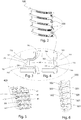
- Fig. 1 shows an exemplary embodiment of a device according to the invention, comprising five light guides 110,120,130,140,150, each with a Lichteinkoppelstelle 112,122, 132,142,152 , a Auskoppelabêt 114,124,134,144,154 and a light guide end 115,125,135,145,155 and the respective optical fibers 110,120,130,140,150, associated light source 111,121,131,141,151 which light in the respective light guide 110, 120,130,140,150 on the Lichteinkoppelstelle 112,122,132,142,152 and a subsequent feed section 113,123,133,143,153 can feed and in the example of Fig.
- decoupling elements 161 exits via a light exit area.
- the decoupling elements 161 of the decoupling sections 114, 124, 134, 144, 154 extend in the example shown in the figures over the entire outcoupling section 114, 124, 134, 114, 154 to the respective optical fiber end 115 , 125 , 135 , 145 , 155 , 155 , as shown by way of example in FIG Fig. 7 is shown on a light guide 110 , wherein a not extending over the entire coupling-out section 115,125,135,145,155 arrangement of the decoupling elements 161 is conceivable.
- decoupling elements 161 of the decoupling sections 114, 124, 134, 144, 154 may be formed as prisms, as in FIG Fig. 8 you can see.
- this opaque region adjoins this surface-expanding, such as the representation of the lens 200 in FIG Fig. 1 shows.
- partially translucent is meant that the light windows 201, 202, 203, 204, 205 have a transmittance of less than 1 in order to attenuate the light emerging from the light guide 110, 120, 130, 140, 150 or from the lead portion 113, 123, 133, 143, 154 .
- the light windows 201, 202, 203, 204, 205 preferably extend from the light guide end 115 , 125, 135, 145, 155 to the light coupling point 112, 122, 132, 142, 152 of the respective light guide 110 , 120, 130, 140, 150, essentially covering them, ie the respective light coupling point 112, 122, 132, 142, 152 is also illuminated by a light window 201 , 202, 203, 204, 205 in such a way that light from the light coupling point 112, 122, 132, 142, 152 or the subsequent feed line section 113, 123, 133, 143, 153 can be at least partially transmitted through the respective light window 201, 202, 203, 204, 205 .
- the lens 200 can be manufactured with the light windows 201, 202, 203, 204, 205 by means of a two-component injection molding process.
- the feed line section of light guides serves to mix the light in order to achieve homogeneous light extraction from the beginning of the coupling-out section or the light exit surface of an optical waveguide, wherein the light from the feed section is usually not coupled out and therefore generally has no outcoupling elements. Nevertheless, a perceptible amount of light can escape via the light coupling-in point and / or the supply line section and influence the light impression of the respective light windows 201, 202, 203, 204, 205 , this counteracting a homogeneous light impression per light window 201, 202, 203, 204, 205 .
- outcoupling elements 162 can be arranged in the respective supply section 113, 123, 133, 143, 155 , as in FIG FIGS. 7 and 8 shown.
- the supply line section of a light guide 201, 202, 203 , 204, 205 ensures thorough mixing of the light fed in
- the outcoupling elements 162 in the supply section 113, 123, 133, 143, 143 of the light guides 110, 120, 130, 140, 150 are designed in such a way that despite the deliberate decoupling of light in the supply section 113, 123, 133, 433, 154 Intermixing of the light is not significantly affected, so that the light prepared for the decoupling section 114,124, 134, 144, 154 in the sense of mixing undergoes substantially no significant losses or changes.
- the decoupling elements 162 of the feed line section 113, 123, 133, 143, 153 are formed in the form of cylindrical grooves, since such a shape has a less strongly directed emission characteristic than a prism commonly used for the decoupling of light, for example in the decoupling section 114,124,134,144,154 of Optical fiber 110,120,130,140,150 are arranged, as exemplified in FIGS. 7 and 8 shown.
- the distance between the individual output coupling elements 162 and their size or the radius of the cylindrical grooves can be the same.
- the distance between the individual outcoupling elements 162 of the supply line region can be selected such that it corresponds to the distance between the individual outcoupling elements 161 of the outcoupling section 114, 124, 134, 144, 154, for example the prisms.
- the size and / or the radius of the cylindrical grooves 162 and the depth of the grooves 162 in the lead section 113, 123 , 133, 143, 155 can be made to run, the dimensions such as size, Distance between the individual grooves, radius of the cylindrical grooves and / or depth along the light guide 110,120,130,140,150 in the direction of the light guide end 115,125,135,145,155 are designed to increase or decrease.
- the light windows may moreover have a non-uniform wall thickness, preferably a wall thickness profile.
- the wall thickness of the light windows 201, 202, 203, 204, 205 can increase or decrease in the direction of the light guide end 115, 125, 135, 145, 155 .
- the light exit direction of the light coupling- in point 112 , 122, 132, 142, 152 runs essentially parallel to the desired light exit direction of the coupling-out section 114, 124, 134, 144, 154, 154 of the light guides 110 , 120, 130, 140, 150 , as in FIG Fig. 1
- the wall thickness or the wall thickness profile of the light windows 201, 202, 203, 204, 205 can be matched to the light intensity of the respectively used light guides 110, 120, 130, 140, 150 or the corresponding light sources 111 , 121, 131, 141, 51, 51 .
- At least one separating wall can be arranged between the next adjacent light windows 201, 202, 203, 204, 205 , which makes it possible to cross-talk a light emitted by a light guide 110, 120, 130, 140, 150 into a light window 201, 202, 203, 204, 205 not assigned to this light guide to prevent.
- the homogeneous light impression of the individual light windows 201, 202, 203, 204, 205 can be improved, since only light of the light guide 110, 120, 130, 140, 150 assigned to the respective light window 201, 202, 203, 204, 205 forms the relevant light component for a desired light impression .
- a crosstalk of light of a light guide in a light guide 201, 202, 203, 204, 205 can between At least one partition wall to be arranged next adjacent optical fibers 110,120,130,140,150 , wherein the at least one partition both crosstalk between adjacent light windows 201, 202, 203, 204, 205 and prevents crosstalk between adjacent light guides.
- the individual light guides 110, 120, 130, 140, 150 arranged in an illumination and / or signaling device according to the invention can be embodied as a one-piece optical waveguide element 100 , as in FIG Fig. 2 illustrated, wherein at least one connecting web 300 between the individual optical fibers 110,120,130,140,150 as a light trap element with at least one decoupling element 310, 311, 312 is formed to to prevent a crossing of light coupled into or fed into an optical waveguide 110, 120, 130, 140, 150 into another optical waveguide 110, 120, 130, 140, 150 by means of total optical reflection, wherein preferably the outcoupling elements 310, 311, 312 decouple light directly to the front - in the light exit direction .
- the light guides 110, 120, 130, 140, 150 and the connecting webs 300 are formed from a material, preferably produced by means of one-component injection molding.
- the connecting webs 300 can essentially be arranged in the region of the respective supply line sections 113 , 123, 133, 143, 155 and light coupling points 112 , 122, 132, 142, 152 of the light guides 110, 120, 130, 140, 150 , as in FIG Fig. 2 shown.
- FIG 3 and 4 A detailed view of two exemplary connecting webs 300 with decoupling elements 310, 311, 312 is shown in FIG 3 and 4 shown.
- decoupling elements 310, 311, 312 include, among other things, defined deflection surfaces 311 with associated defined decoupling surfaces 312, as well as prisms 310, for example in the form of projecting serrations, which in turn may have defined decoupling surfaces.
- defined deflection surfaces are surfaces which are deliberately arranged to guide or direct the direction of a certain amount of light rays in the direction of a decoupling surface assigned to this defined deflection surface, wherein a defined deflection surface and its associated decoupling surface are arranged such that the deflected, determined amount of light rays orthogonally incident on the decoupling surface to enable efficient decoupling.
- Fig. 3 the illustrated, formed as a light trap connecting web 300 no direct connection in the sense of the shortest possible link between two exemplary optical fibers of the light guide element 100 , but is shaped to a certain extent as a bulge.
- the connecting web 300 or the light trap defined deflection 311 and 311 at least one associated defined decoupling surface 312 , wherein the defined deflection 311 and the associated decoupling surface 312 may be inclined 45 degrees to each other, so that light rays in the 45 degree angle the deflecting surface 311 are deflected by 90 degrees and can decouple from the decoupling surface 312 which is associated with this deflection surface 311 - in the example Fig. 3 essentially in the light exit direction of the light guides 110, 120, 130, 140, 150, which is illustrated by the exemplary, drawn beam paths 701, 703 .
- the light beams not decoupled by such a defined deflection surface 311 and its associated decoupling surface 312 can move through further deflections within the connecting web 300 , prisms 310 being arranged for this purpose, for example in the form of projecting serrations as further decoupling elements, as in FIG Fig. 3 is shown by an exemplary beam path 702 .
- different sizes of prisms 310 may be arranged on the connecting web.
- Fig. 4 shows another example of a connecting web 300, which is designed as a light trap.
- the connecting web 300 is a direct connection in the sense of the shortest possible connection between two exemplary optical fibers of the light guide element 100 , in which case two defined deflection 311 are arranged in the form of notches with respective decoupling surfaces 312 .
- Exemplary ray paths 704, 705 in FIG Fig. 4 illustrate the already mentioned above principle of the deflection surfaces 311 and the associated decoupling surfaces 312st
- These defined deflection surfaces 311 are arranged such that a direct optical connection between nearest adjacent optical fibers within the connecting web 300 in the sense of a straight light beam is not given.
- connecting webs 300 or light traps are also possible, whereby the number and choice of the decoupling elements 310, 311, 312 can also be matched to the geometry of the connecting webs 300 .
- At least one separating wall can be arranged between the next adjacent light windows 201, 202, 203, 204, 205 , which makes it possible to cross-talk a light emitted by a light guide 110, 120, 130, 140, 150 into a light window 201, 202, 203, 204, 205 not assigned to this light guide to prevent.
- the homogeneous light impression of the individual light windows 201, 202, 203, 204, 205 can be improved, since only light of the light guide 110, 120, 130, 140, 150 assigned to the respective light window 201, 202, 203, 204, 205 forms the relevant light component for a desired light impression .
- a crosstalk of light of a light guide in a light guide 201, 202, 203, 204, 205 can between At least one partition wall to be arranged next adjacent optical fibers 110,120,130,140,150 , wherein the at least one partition both crosstalk between adjacent light windows 201, 202, 203, 204, 205 and prevents crosstalk between adjacent light guides.
- Such a partition can be realized by various embodiments, as described in more detail below.
- the light guide element 100 can in a support frame 400, which has recesses 401 for the corresponding light guide of the light guide element 100 and exemplified in Fig. 5 can be arranged, wherein the recesses 402 of the respective light guide of the light guide element 100 can be performed in the support frame 400 such that a partition wall 410 is formed between the next adjacent light guides, wherein the respective partition walls 410 prevent transmission or crosstalk of emitted light of a light guide into a next adjacent light guide.
- the lens 200 may be arranged with respect to the support frame 400 such that the partitions 410 of the support frame 400 simultaneously also a transmission or crosstalk of emitted light of a light guide 110,120,130,140,150 in a this light guide 110,120,130,140,150 not associated light window 201, 202, 203, 204, 205, 206 prevent.
- the support frame 400 can also be designed so that the lead portions 113,123,133,143,153 and the Lichteinkoppelstellen 112,122,132, 142,152 not find in the recesses 401 place, such as the in Fig. 5 illustrated carrier frame 400, and thus a crosstalk of in a light guide 110,120, 130,140,150 coupled or fed light into an adjacent light guide 110, 120,130,140,150 can take place in these areas quite.
- a diaphragm component 500 with partitions 501 is arranged in the region of the supply line sections 113, 123, 133, 143, 153 and the light coupling points 112, 122, 132, 142, 152 or at least in the areas where no recesses 401 of the support frame 400 are provided for the respective light guides 110, 120, 130, 140, 150 .
- FIG Fig. 6 An exemplary diaphragm component is shown in FIG Fig. 6 illustrated, wherein the diaphragm member 500 alternative, at least partially transparent aperture portions 502 , which are each associated with a light guide 110,120,130,140,150 and a wall thickness curve , as described above, may have.
- the entire diaphragm component 500 is partially transparent.
- diaphragm sections 502 designed with a wall thickness profile can be used as an alternative to the light windows 201, 202, 203, 204, 205 having a wall thickness profile in order to produce a homogeneous light impression per light window 201, 202, 203, 204, 205 , whereby a combination of wall thickness profiles of the light windows 201, 202, 203, 204, 205 and the diaphragm sections 502 would also be conceivable.
- the light windows 201, 202, 203, 204, 205 may be colored, either uniformly in one color or in different colors, respectively.
- 161 Decoupling elements in the supply line section ... 162 Lens ... 200 Light windows ... 201, 202, 203, 204, 205 Connecting webs ... 300 Decoupling element light trap ... 310, 311, 312 Prisms ... 310 Deflection ... 311 Outcoupling ... 312 Support frames ... 400 Recess ... 401 Partition walls (support frame) ... 410 Iris component ... 500 Partitions ... 501 Shutter section ... 502 Beam paths ... 701, 702, 703, 704, 705
Landscapes
- Engineering & Computer Science (AREA)
- General Engineering & Computer Science (AREA)
- Physics & Mathematics (AREA)
- Optics & Photonics (AREA)
- Mechanical Engineering (AREA)
- Microelectronics & Electronic Packaging (AREA)
- General Physics & Mathematics (AREA)
- Optical Couplings Of Light Guides (AREA)
- Optical Communication System (AREA)
- Light Guides In General And Applications Therefor (AREA)
- Planar Illumination Modules (AREA)
- Non-Portable Lighting Devices Or Systems Thereof (AREA)
Abstract
Description
- Die Erfindung betrifft eine Beleuchtungs- und/ oder Signalisierungsvorrichtung für ein Kraftfahrzeug, umfassend zumindest zwei Lichtleiter mit einer Lichteinkoppelstelle und einem Auskoppelabschnitt, sowie zumindest eine den jeweiligen Lichtleitern zugeordnete Lichtquelle, welche Licht in die jeweiligen Lichtleiter über die Lichteinkoppelstelle und einem nachfolgenden Zuleitungsabschnitt einspeist, wobei in den Lichtleitern eingespeistes Licht mittels im Auskoppelabschnitt der jeweiligen Lichtleiter angeordnete Auskoppelelemente über einen Lichtaustrittsbereich im Auskoppelabschnitt der jeweiligen Lichtleiter zur Bildung einer ersten Lichtverteilung austritt.
- Weiters betrifft die Erfindung einen Kraftfahrzeugscheinwerfer, welcher zumindest eine erfindungsgemäße Beleuchtungs- und/ oder Signalisierungsvorrichtung umfasst.
- Da Elektrofahrzeuge, insbesondere elektrisch betriebene Kraftfahrzeuge, immer weitere Verbreitung finden, kann eine Information über den Zustand der noch verbleibenden elektrischen Energie eines solchen Kraftfahrzeuges von Bedeutung sein.
- Dies kann mit einfachen Mitteln auf einer Armaturenanzeige realisiert werden, wobei auch eine eigene Beleuchtungs- und/ oder Signalisierungsvorrichtung, welche außerhalb des Fahrzeugs angeordnet sein kann, möglich ist.
- Aus dem Stand der Technik beschreibt unter anderem die
DE 10 2011121 058 A1 eine Anzeige über einen Energiespeicher eines Fahrzeugs, welche Anzeige mit Leuchtmitteln des Fahrzeugs dargestellt wird, wobei mit denselben Leuchtmitteln eine Lichtfunktion des Fahrzeugs realisiert werden, welche keinen Bezug zu dem Energiespeicher aufweist. - Aus der
DE 10 2007 005 551 A1 ist eine Leuchte bekannt, wobei diese Leuchte ein Gehäuse und eine Lichtscheibe, hinter der ein Leuchtmittel vorgesehen ist, aufweist, und wobei die Lichtscheibe in mindestens zwei getrennte lichtdurchlässige und mit Abstand voneinander angeordnete Lichtfenster aufgeteilt ist, die gleiche oder unterschiedliche Leuchtfunktionen haben. Zwischen diesen Lichtfenstern ist ein wenigstens teilweise lichtundurchlässiger Bereich vorhanden, wobei im lichtundurchlässigen Bereich wenigstens ein zusätzlicher lichtdurchlässiger Bereich vorgesehen ist, um ein von dem Gesetzgeber gefordertes zusammenhängendes Lichtfenster umzusetzen, wenn die beiden Lichtfenster die gleiche Lichtfunktion erfüllen. - Es ist Aufgabe der Erfindung eine verbesserte Beleuchtungs- und/ oder Signalisierungsvorrichtung bereitzustellen.
- Diese Aufgabe wird dadurch gelöst, dass die Lichtleiter als einstückiges Lichtleiterelement ausgebildet sind, wobei zumindest ein Verbindungsteg zwischen den einzelnen Lichtleitern als Lichtfallenelement mit zumindest einem Auskoppelelement ausgebildet ist, um ein Übertreten von in einem Lichtleiter eingespeistes Licht in einen anderen Lichtleiter mittels optischer Totalreflexion zu verhindern.
- Dadurch wird eine Montagezeitverkürzung sowie eine Kostenreduktion ermöglicht.
- Eine solche Beleuchtungs- und/oder Signalisierungsvorrichtung kann beispielsweise zur Erzeugung einer Blinklichtverteilung bzw. Blinklichtfuntion, einer Abblendlichtverteilung und/oder als Ladestandsanzeige eines Fahrzeuges, insbesondere eines Elektrokraftfahrzeuges, vorgesehen sein.
- Mit Vorteil ist vorgesehen, wenn die Lichtleiter und der zumindest eine Verbindungssteg aus einem Werkstoff, vorzugsweise mittels Einkomponenten-Spritzgießverfahren hergestellt, gebildet sind.
- Vorteilhafterweise kann der zumindest eine Verbindungssteg im Wesentlichen im Bereich der jeweiligen Zuleitungsabschnitte und Lichteinkoppelstellen der Lichtleiter oder am Lichtleiterende der jeweiligen Lichtleiter angeordnet sein.
- Bei einer beispielhaften Ausführungsform kann vorgesehen sein, dass Vorrichtung ferner zumindest eine teilweise lichtdurchlässige Lichtscheibe umfasst, welche in Lichtaustrittsrichtung nach den Lichtleitern angeordnet ist, wobei die Lichtscheibe zumindest zwei durch einen opaken Bereich voneinander getrennte, zumindest teilweise lichtdurchlässige Bereiche - im weiteren Verlauf Lichtfenster genannt - aufweist, welche jeweils zumindest einem der zumindest zwei Lichtleiter zugeordnet sind und deren Anordnung in Bezug auf die jeweiligen Lichtleiter eine zweite Lichtverteilung des aus dem Lichtaustrittsbereich austretenden Lichts ermöglicht.
- Mit "zumindest teilweise lichtdurchlässig" ist gemeint, dass die Lichtfenster einen Transmissionsgrad kleiner 1 aufweisen und dadurch das von dem Lichtleiter austretende Licht abschwächen bzw. in Hinblick auf den Transmissionsgrad abschwächen - gleiches gilt für "zumindest teilweises Durchstrahlen".
- So hätte ein komplett lichtundurchlässiges bzw. opakes Medium einen Transmissionsgrad gleich Null bzw. im Wesentlichen gleich Null.
- Hingegen besitzen Medien, welche die Intensität des transmittierten Lichts unverändert lassen, einen Transmissionsgrad gleich Eins bzw. im Wesentlichen gleich Eins.
- Weiters kann es günstig sein, wenn die Lichtleiter voneinander unabhängig ansteuerbar sind.
- Damit ist vor allem gemeint, dass die Lichtquellen, welche den jeweiligen Lichtleitern zugeordnet sind, unabhängig voneinander ansteuerbar sind, um ein Lauflicht und/ oder eine Ladezustandsanzeige zu realisieren.
- Hierbei können die Lichtquellen auch dimmbar sein.
- Weiterhin kann es günstig sein, wenn die Lichtscheibe einstückig in einem Zweikomponenten-Spritzgießverfahren hergestellt wurde.
- Dadurch wird eine reale Montagezeitverkürzung der Beleuchtungs- und/ oder Signalisierungsvorrichtung ermöglicht.
- Ebenso wird durch die Reduktion der einzelnen Bauteile eine Kostenverminderung ermöglicht.
- Überdies wurden bei Rütteltests keine Abriebe zwischen den Lichtfenstern und den opaken Bereichen aufgrund der durch das Zweikomponenten-Spritzgießverfahren einstückig hergestellten Lichtscheibe festgestellt.
- Bei einer zweckmäßigen Ausgestaltung kann vorgesehen sein, dass sich die jeweiligen Lichtfenster der Lichtscheibe bis einschließlich dem Bereich der Lichteinkoppelstelle und des Zuleitungsabschnittes des jeweiligen Lichtleiters erstrecken.
- Es kann vorgesehen sein, dass zwischen nächst benachbarten Lichtleitern zumindest eine Trennwand angeordnet ist, um ein Übersprechen von emittiertem Licht eines Lichtleiters in einen nächst benachbarten Lichtleiter zu verhindern.
- Bei einer weitere Ausführungsform kann vorgesehen sein, dass das Lichtleiterelement in einem Tragerahmen, welcher Ausnehmungen für die entsprechenden Lichtleiter des Lichtleiterelements aufweist, angeordnet ist, wobei die Ausnehmungen der jeweiligen Lichtleiter des Lichtleiterelements ein Durchstrahlen und/ oder Übersprechen von emittiertem Licht eines Lichtleiters in einen nächst benachbarten Lichtleiter verhindern.
- Ferner kann vorgesehen sein, dass zwischen nächst benachbarten Lichtfenstern zumindest eine Trennwand angeordnet ist, welche ermöglicht, ein Übersprechen eines von einem Lichtleiter emittierten Lichts in ein diesem Lichtleiter nicht zugeordnetes Lichtfenster zu verhindern.
- Es kann vorteilhaft sein, wenn die Lichtfenster eine variierende Wandstärke aufweisen.
- Dabei kann es günstig sein, wenn die Lichtfenster einen Wandstärkenverlauf aufweisen, wobei die Wandstärke in Richtung Lichtleiterende des jeweiligen Lichtleiters abnimmt.
- Ebenso kann es günstig sein, wenn die Lichtfenster einen Wandstärkenverlauf aufweisen, wobei die Wandstärke in Richtung Lichtleiterende des jeweiligen Lichtleiters zunimmt.
- Eine praxisgerechte Weiterentwicklung der Erfindung kann vorsehen, dass die Auskoppelelemente im Auskoppelabschnitt der jeweiligen Lichtleiter des Lichtleiterelements als Prismen ausgebildet sind.
- Dabei kann vorgesehen sein, dass die Auskoppelelemente im Auskoppelabschnitte der jeweiligen Lichtleiter einen Größen- und/ oder Abstandsverlauf aufweisen.
- In einer weiteren praxisgerechten Ausführungsform der Erfindung kann vorgesehen sein, dass im Zuleitungsabschnitt der jeweiligen Lichtleiter Auskoppelelemente angeordnet sind, um ein Austreten des von der zumindest einen Lichtquelle eingespeisten Lichts abseits des Auskoppelabschnitts zu ermöglichen.
- Mit Vorteil kann hierbei vorgesehen sein, dass die Auskoppelelemente im Zuleitungsabschnitt der jeweiligen Lichtleiter als zylindrisch geformte Rillen ausgebildet sind.
- Vorteilhafterweise kann die Größe bzw. können die Dimensionen der Auskoppelelemente im Zuleitungsabschnitt der jeweiligen Lichtleiter entlang des jeweiligen Lichtleiters in Richtung Lichtleiterende zu- oder abnehmen.
- Weiters kann es vorteilhaft sein, wenn die zumindest eine Lichtquelle der jeweiligen Lichtleiter als LED ausgebildet ist.
- Es sei darauf hingewiesen, dass die zumindest eine Lichtquelle auch mehrere LEDs umfassen kann, wobei diese LEDs unabhängig voneinander ansteuerbar und/oder dimmbar sein können.
- Es kann günstig sein, wenn die Lichtleiter voneinander unabhängig ansteuerbar sind.
- Ebenso kann es günstig sein, wenn die Lichtquellen unabhängig voneinander dimmbar sind.
- Bei einer vorteilhaften Variante kann im Bereich der Lichteinkoppelstelle und des Zuleitungsabschnitts ein Blenden-Bauteil mit Blendenabschnitten angeordnet sein, wobei die Blendenabschnitte teilweise lichtdurchlässig ausgebildet sind und je zumindest einem Lichtleiter zugeordnet sind.
- Es kann zweckmäßig sein, wenn die Blendenabschnitte einen Wandstärkenverlauf in Richtung Lichtleiterende aufweist, wobei die Wandstärke in Richtung Lichtleiterende zu- oder abnimmt.
- Weiters kann es vorteilhaft sein, wenn das Blenden-Bauteil zwischen nächst benachbarten Blendenabschnitten zumindest eine Trennwand aufweist, um ein Durchstrahlen und/oder Übersprechen von emittiertem Licht im Bereich der Lichteinkoppelstelle und des Zuleitungsabschnitts eines Lichtleiters in einen nächst benachbarten Lichtleiter zu verhindern.
- Nachfolgend wird die Erfindung anhand von Zeichnungen näher erläutert. Hierbei zeigt:
-
Fig. 1 eine Explosionsansicht einer beispielhaften Beleuchtungs- und/ oder Signalisierungsvorrichtung nach der Erfindung, -
Fig. 2 ein beispielhaftes Lichtleiterelement, -
Fig. 3 und 4 jeweils eine Detailansicht eines beispielhaften Verbindungssteges des Lichtleiterelements ausFig. 2 , -
Fig. 5 einen Tragerahmen für das Lichtleiterelement, -
Fig. 6 ein beispielhaftes Blenden-Bauteil, -
Fig. 7 einen exemplarischen Lichtleiter mit einem Zuleitungs- und einem Auskoppelabschnitt, und -
Fig. 8 eine Detailansicht des Lichtleiters ausFig. 7 . -
Fig. 1 zeigt eine beispielhafte Ausführungsform einer erfindungsgemäßen Vorrichtung, umfassend fünf Lichtleiter 110,120,130,140,150, mit je einer Lichteinkoppelstelle 112,122, 132,142,152, einem Auskoppelabschnitt 114,124,134,144,154 und einem Lichtleiterende 115,125,135,145,155 sowie eine den jeweiligen Lichtleitern 110,120,130,140,150, zugeordnete Lichtquelle 111,121,131,141,151, welche Licht in den jeweiligen Lichtleiter 110, 120,130,140,150 über die Lichteinkoppelstelle 112,122,132,142,152 und einem nachfolgenden Zuleitungsabschnitt 113,123,133,143,153 einspeisen kann und in dem Beispiel ausFig. 1 als LED ausgeführt ist und unabhängig voneinander ansteuerbar und/ oder dimmbar sein können, wobei in den Lichtleitern 110,120,130,140,150 eingespeistes Licht mittels im Auskoppelabschnitt 114,124,134,144,154 angeordnete Auskoppelelemente 161 über einen Lichtaustrittsbereich austritt. - Die Auskoppelelemente 161 der Auskoppelabschnitte 114, 124, 134, 144,154 erstrecken sich in dem in den Figuren gezeigten Beispiel über den gesamten Auskoppelabschnitt 114,124, 134,144,154 bis zum jeweiligen Lichtleiterende 115,125,135,145,155, wie exemplarisch in
Fig. 7 an einem Lichtleiter 110 gezeigt ist, wobei eine sich nicht über den gesamten Auskoppelabschnitt 115,125,135,145,155 erstreckende Anordnung der Auskoppelelemente 161 denkbar ist. - Ferner können die Auskoppelelemente 161 der Auskoppelabschnitte 114,124,134,144,154 als Prismen ausgebildet sein, wie in
Fig. 8 zu sehen ist. - Weiters ist in
Fig. 1 eine in Richtung des von den Lichtleitern 110,120,130,140,150 emittierten Lichts - in weiterer Folge Lichtaustrittsrichtung genannt - nachgeschaltete Lichtscheibe 200 mit fünf durch einen opaken Bereich voneinander getrennte, teilweise lichtdurchlässige Bereiche - im weiteren Verlauf Lichtfenster 201, 202, 203, 204, 205 genannt, welche jeweils einem der Lichtleiter 110,120,130,140,150 zugeordnet sind, dargestellt, wobei die Anordnung der Lichtfenster 201, 202, 203, 204, 205 in Bezug auf die jeweiligen Lichtleiter 110,120,130,140,150 ein zumindest teilweises Durchstrahlen des aus dem Lichtaustrittsbereich der jeweiligen Lichtleiter 110,120,130,140,150 austretenden Lichts ermöglicht. - Dieser opake Bereich schließt bei einer flächenhaften Ausbildung der Lichtfenster an diesen flächenerweiternd an, wie die Darstellung der Lichtscheibe 200 in
Fig. 1 zeigt. - Mit "teilweise lichtdurchlässig" ist gemeint, dass die Lichtfenster 201, 202, 203, 204, 205 einen Transmissionsgrad kleiner 1 aufweisen, um das aus dem Lichtleiter 110,120,130,140,150 bzw. aus dem Zuleitungsabschnitt 113,123,133,143,153 austretende Licht abzuschwächen.
- Überdies erstrecken sich die Lichtfenster 201, 202, 203, 204, 205 vorzugsweise von dem Lichtleiterende 115,125,135,145,155 bis zur Lichteinkoppelstelle 112, 122,132, 142, 152 des jeweiligen Lichtleiters 110,120,130,140,150 und überdecken diese im Wesentlichen, d.h. auch die jeweilige Lichteinkoppelstelle 112,122,132,142,152 wird von einem Lichtfenster 201, 202, 203, 204, 205 derart überdeckt, dass Licht aus der Lichteinkoppelstelle 112,122,132, 142,152 bzw. dem nachfolgenden Zuleitungsabschnitt 113,123,133,143,153 durch das jeweilige Lichtfenster 201, 202, 203, 204, 205 zumindest teilweise durchstrahlen kann.
- Des Weiteren kann die Lichtscheibe 200 mit den Lichtfenstern 201, 202, 203, 204, 205mittels einem Zweikomponenten-Spritzgießverfahren hergestellt werden.
- Im Allgemeinen dient der Zuleitungsabschnitt von Lichtleitern zur Durchmischung des Lichts, um ab Beginn des Auskoppelabschnitts bzw. der Lichtaustrittsfläche eines Lichtleiters eine homogene Lichtauskopplung zu erreichen, wobei das Licht aus dem Zuleitungsabschnitt üblicherweise nicht ausgekoppelt wird und deshalb in der Regel keine Auskoppelelemente aufweist. Nichtsdestotrotz kann eine wahrnehmbare Lichtmenge über die Lichteinkoppelstelle und/oder dem Zuleitungsabschnitt austreten und den Leuchteindruck der jeweiligen Lichtfenster 201, 202, 203, 204, 205 beeinflussen, wobei dies einem homogenen Leuchteindruck je Lichtfenster 201, 202, 203, 204, 205 entgegensteht.
- Um gezielt Licht aus den Zuleitungsabschnitten 113,123,133,143,153 auszukoppeln und dadurch den einzelnen Lichtfenstern 201, 202, 203, 204, 205 einen homogeneren Leuchteindruck zu verleihen, können Auskoppelelemente 162 im jeweiligen Zuleitungsabschnitt 113,123,133,143,153 angeordnet sein, wie in
Fig. 7 und 8 gezeigt. - Da im Allgemeinen der Zuleitungsabschnitt eines Lichtleiters 201, 202, 203, 204, 205 für eine Durchmischung des eingespeisten Lichts sorgt, sind die Auskoppelelemente 162 im Zuleitungsabschnitt 113,123,133,143,153 der Lichtleiter 110,120,130,140,150 derart ausgeführt, dass trotz der gezielten Auskoppelung von Licht im Zuleitungsabschnitt 113, 123,133,143,153 die Durchmischung des Lichts nicht maßgeblich beeinflusst wird, sodass das für den Auskoppelabschnitt 114,124, 134, 144, 154 im Sinne der Durchmischung vorbereitete Licht im Wesentlichen keine maßgeblichen Verluste bzw. Veränderungen erfährt.
- Hierfür sind die Auskoppelelemente 162 des Zuleitungsabschnitts 113, 123, 133, 143, 153 in Form von zylindrischen Rillen ausgebildet, da eine solche Form eine weniger stark gerichtete Abstrahlcharakteristik aufweist als ein üblicherweise für die Auskoppelung von Licht verwendete Prismen, die beispielsweise im Auskoppelabschnitt 114,124,134,144,154 des Lichtleiters 110,120,130,140,150 angeordnet sind, wie exemplarisch in
Fig. 7 und 8 dargestellt. - Wenn die Auskoppelelemente 162 im Zuleitungsabschnitt 113,123,133,143,153 nur über einen kurzen Abschnitt entlang des Zuleitungsabschnitts 113,123,133,143,153 angeordnet werden, kann der Abstand zwischen den einzelnen Auskoppelelementen 162 und deren Größe bzw. der Radius der zylindrischen Rillen gleich verlaufen.
- In diesem Fall kann der Abstand zwischen den einzelnen Auskoppelelementen 162 des Zuleitungsbereichs so gewählt werden, dass er dem Abstand zwischen den einzelnen Auskoppelelementen 161 des Auskoppelabschnitts 114,124,134,144,154, beispielsweise der Prismen, entspricht.
- Bei einer Auskopplung des Lichts über einen längeren Abschnitt bzw. Bereich des Zuleitungsabschnitts 113,123,133,143,153, kann die Größe und/oder der Radius der zylindrischen Rillen 162 sowie die Tiefe der Rillen 162 in dem Zuleitungsabschnitt 113,123, 133,143,153 verlaufend ausgeführt werden, wobei die Dimensionen wie Größe, Abstand zwischen den einzelnen Rillen, Radius der zylindrischen Rillen und/oder Tiefe entlang des Lichtleiters 110,120,130,140,150 in Richtung Lichtleiterende 115,125,135,145,155 zu- oder abnehmend ausgeführt sind.
- Für eine verbesserte Homogenisierung des Leuchteindrucks der einzelnen Lichtfenster 201, 202, 203, 204, 205 können die Lichtfenster überdies eine nicht gleichbleibende Wandstärke, vorzugsweise einen Wandstärkenverlauf, aufweisen.
- Je nachdem welche Ausformung die Lichtleiter 110,120,130,140,150 im Bereich der Lichteinkoppelstelle 112,122,132,142,152 und dem Zuleitungsabschnitt 113,123,133,143, 153 im Bezug zur gewünschten Lichtaustrittsrichtung aufweisen, kann die Wandstärke der Lichtfenster 201, 202, 203, 204, 205 in Richtung Lichtleiterende 115,125,135,145,155 zu- oder abnehmen.
- Falls die Lichtaustrittsrichtung der Lichteinkoppelstelle 112,122,132,142,152 im Wesentlichen parallel zur gewünschten Lichtaustrittsrichtung des Auskoppelabschnitts 114, 124,134,144,154 der Lichtleiter 110,120,130,140,150 verläuft, wie in
Fig. 1 gezeigt, so kann es ratsam sein, den Wandstärkenverlauf der Lichtfenster 201, 202, 203, 204, 205 in Richtung Lichtleiterende 115,125,135,145,155 abnehmend zu gestalten. - Bei einer Lichtaustrittsrichtung der Lichteinkoppelstelle 112,122,132,142,152, die im Wesentlichen orthogonal zur gewünschten Lichtaustrittsrichtung des Auskoppelabschnitts 114,124,134,144,154 des Lichtleiters 110,120,130,140,150 verläuft, kann ein in Richtung Lichtleiterende 115,125,135,145,155 zunehmender Wandstärkenverlauf der Lichtfenster 201, 202, 203, 204, 205 wünschenswert sein.
- Grundsätzlich kann die Wandstärke bzw. der Wandstärkenverlauf der Lichtfenster 201, 202, 203, 204, 205 nach der Lichtstärke der jeweilig verwendeten Lichtleiter 110, 120,130, 140, 150 bzw. der entsprechenden Lichtquellen 111,121,131,141,151 abgestimmt sein.
- Des Weiteren kann zwischen nächst benachbarten Lichtfenstern 201, 202, 203, 204, 205zumindest eine Trennwand angeordnet sein, welche ermöglicht, ein Übersprechen eines von einem Lichtleiter 110,120,130,140,150 emittierten Lichts in ein diesem Lichtleiter nicht zugeordnetes Lichtfenster 201, 202, 203, 204, 205 zu verhindern.
- Dadurch kann der homogene Leuchteindruck der einzelnen Lichtfenster 201, 202, 203, 204, 205 verbessert werden, da ausschließlich Licht des dem jeweiligen Lichtfenster 201, 202, 203, 204, 205 zugeordneten Lichtleiters 110,120,130,140,150 den maßgeblichen Lichtanteil für einen gewünschten Leuchteindruck bildet.
- Um ein Übersprechen von emittierten Licht eines Lichtleiters 110,120,130,140,150 in einen nächst benachbarten Lichtleiter 110,120,130,140,150 und damit auch ein Übersprechen von Licht eines Lichtleiters in ein diesem Lichtleiter nicht zugeordnetes Lichtfenster 201, 202, 203, 204, 205 über einen nächst benachbarten Lichtleiter zu verhindern, kann zwischen nächst benachbarten Lichtleitern 110,120,130,140,150 zumindest eine Trennwand angeordnet sein, wobei die zumindest eine Trennwand sowohl ein Übersprechen zwischen benachbarten Lichtfenstern 201, 202, 203, 204, 205 als auch ein Übersprechen zwischen benachbarten Lichtleitern verhindert.
- Weiters können die einzelnen in einer erfindungsgemäßen Beleuchtungs- und/ oder Signalisierungsvorrichtung angeordneten Lichtleiter 110,120,130,140,150 als einstückiges Lichtleiterelement 100 ausgebildet sind, wie in
Fig. 2 dargestellt, wobei zumindest ein Verbindungssteg 300 zwischen den einzelnen Lichtleitern 110,120,130,140,150 als Lichtfallenelement mit zumindest einem Auskoppelelement 310, 311, 312 ausgebildet ist, um ein Übertreten von in einem Lichtleiter 110,120,130,140,150 eingekoppeltes bzw. eingespeistes Licht in einen anderen Lichtleiter 110,120,130,140,150 mittels optischer Totalreflexion zu verhindern, wobei vorzugsweise die Auskoppelelemente 310, 311, 312 Licht direkt nach vorne - in Lichtaustrittsrichtung - auskoppeln. - Die Lichtleiter 110, 120, 130,140, 150 sowie die Verbindungsstege 300 sind aus einem Werkstoff gebildet, vorzugsweise mittels Einkomponenten-Spritzgießverfahren hergestellt.
- Die Verbindungsstege 300 können im Wesentlichen im Bereich der jeweiligen Zuleitungsabschnitte 113,123,133,143,153 und Lichteinkoppelstellen 112,122,132,142,152 der Lichtleiter 110, 120,130, 140, 150 angeordnet sein, wie in
Fig. 2 gezeigt. - Eine Detailansicht zweier beispielhafter Verbindungsstege 300 mit Auskoppelelementen 310, 311, 312 ist in
Fig. 3 und 4 gezeigt. - Zu diesen Auskoppelelementen 310, 311, 312 zählen unter anderem definierte Umlenkflächen 311 mit zugeordneten definierten Auskoppelflächen 312, sowie Prismen 310, beispielsweise in Form von vorragenden Zacken, die wiederum definierte Auskoppelflächen aufweisen können.
- Da grundsätzlich das gesamte Lichtleiterelement 100 bzw. die Verbindungsstege 300 aufgrund des gewählten Materials Umlenkflächen sowie Auskoppelflächen beinhaltet bzw. jede Fläche in Bezug auf einen bestimmten Lichtstrahl unter einem bestimmten Winkel als Umlenkfläche oder Auskoppelfläche dienen kann, sind definierte Umlenkflächen solche Flächen, die bewusst angeordnet werden, um die Richtung einer bestimmten Menge an Lichtstrahlen in Richtung einer dieser definierten Umlenkfläche zugeordneten Auskoppelfläche zu führen bzw. zu lenken, wobei eine definierte Umlenkfläche und die ihr zugeordnete Auskoppelfläche derart angeordnet sind, dass die umgelenkte, bestimmte Menge an Lichtstrahlen orthogonal auf die Auskoppelfläche einfallen, um ein effizientes Auskoppeln zu ermöglichen.
- In
Fig. 3 weist der dargestellte, als Lichtfalle ausgebildete Verbindungssteg 300 keine direkte Verbindung im Sinne der kürzest möglichen Verbindungsstrecke zwischen zwei exemplarischen Lichtleitern des Lichtleiterelements 100 auf, sondern ist gewissermaßen als Ausbuchtung geformt. - Aufgrund dieser ausgebuchteten Form ist es möglich - im Vergleich zu einer direkten Verbindung im obigen Sinne - mehr Auskoppelelemente 310, 311, 312 anzuordnen und so die Effizienz der Lichtfalle zu erhöhen.
- Weiters weist der Verbindungssteg 300 bzw. die Lichtfalle definierte Umlenkflächen 311 und diesen Umlenkflächen 311 zumindest eine zugeordnete definierte Auskoppelfläche 312 auf, wobei die definierte Umlenkfläche 311 und die zugeordnete Auskoppelfläche 312 45 Grad zueinander geneigt sein können, sodass Lichtstrahlen, die im 45 Grad Winkel auf die Umlenkfläche 311 einfallen um 90 Grad umgelenkt werden und aus der Auskoppelfläche 312, die dieser Umlenkfläche 311 zugeordnet ist, auskoppeln können - in dem Beispiel aus
Fig. 3 im Wesentlichen in Lichtaustrittsrichtung der Lichtleiter 110,120,130,140,150, was durch die beispielhaften, eingezeichneten Strahlengänge 701, 703 dargestellt ist. - Die durch eine solche definierte Umlenkfläche 311 und der ihr zugeordneten Auskoppelfläche 312 nicht ausgekoppelten Lichtstrahlen können sich durch weitere Umlenkungen innerhalb des Verbindungssteges 300 fortbewegen, wobei für diese Zwecke Prismen 310 beispielweise in Form von vorragenden Zacken als weitere Auskoppelelemente angeordnet sind, wie in
Fig. 3 durch einen beispielhaften Strahlengang 702 dargestellt ist. - Es können beispielsweise verschiedene Größen von Prismen 310 an dem Verbindungssteg angeordnet sein.
-
Fig. 4 zeigt ein weiteres Beispiel eines Verbindungssteges 300, der als Lichtfalle ausgebildet ist. Hierbei stellt der Verbindungssteg 300 eine direkte Verbindung im Sinne der kürzest möglichen Verbindungsstrecke zwischen zwei exemplarischen Lichtleitern des Lichtleiterelements 100 dar, wobei in diesem Fall zwei definierte Umlenkflächen 311 in Form von Einkerbungen mit jeweiligen Auskoppelflächen 312 angeordnet sind. Beispielhafte Strahlengänge 704, 705 inFig. 4 illustrieren das bereits oben erwähnte Prinzip der Umlenkflächen 311 und den zugehörigen Auskoppelflächen 312. - Diese definierten Umlenkflächen 311 sind derart angeordnet, dass eine direkte optische Verbindung zwischen nächst benachbarten Lichtleitern innerhalb des Verbindungssteges 300 im Sinne eines geraden Lichtstrahls nicht gegeben ist.
- Es sei darauf hingewiesen, dass auch andere Ausformungen der Verbindungsstege 300 bzw. Lichtfallen möglich sind, wobei auch die Anzahl und Wahl der Auskoppelelemente 310, 311, 312 jeweils auf die Geometrie der Verbindungsstege 300 abgestimmt sein können.
- Des Weiteren kann zwischen nächst benachbarten Lichtfenstern 201, 202, 203, 204, 205 zumindest eine Trennwand angeordnet sein, welche ermöglicht, ein Übersprechen eines von einem Lichtleiter 110,120,130,140,150 emittierten Lichts in ein diesem Lichtleiter nicht zugeordnetes Lichtfenster 201, 202, 203, 204, 205 zu verhindern.
- Dadurch kann der homogene Leuchteindruck der einzelnen Lichtfenster 201, 202, 203, 204, 205 verbessert werden, da ausschließlich Licht des dem jeweiligen Lichtfenster 201, 202, 203, 204, 205 zugeordneten Lichtleiters 110,120,130,140,150 den maßgeblichen Lichtanteil für einen gewünschten Leuchteindruck bildet.
- Um ein Übersprechen von emittierten Licht eines Lichtleiters 110,120,130,140,150 in einen nächst benachbarten Lichtleiter 110,120,130,140,150 und damit auch ein Übersprechen von Licht eines Lichtleiters in ein diesem Lichtleiter nicht zugeordnetes Lichtfenster 201, 202, 203, 204, 205 über einen nächst benachbarten Lichtleiter zu verhindern, kann zwischen nächst benachbarten Lichtleitern 110,120,130,140,150 zumindest eine Trennwand angeordnet sein, wobei die zumindest eine Trennwand sowohl ein Übersprechen zwischen benachbarten Lichtfenstern 201, 202, 203, 204, 205 als auch ein Übersprechen zwischen benachbarten Lichtleitern verhindert.
- Eine solche Trennwand kann durch verschiedene Ausführungsformen realisiert werden, wie nachstehend näher beschrieben ist.
- Das Lichtleiterelement 100 kann in einem Tragerahmen 400, welcher Ausnehmungen 401 für die entsprechenden Lichtleiter des Lichtleiterelements 100 aufweist und beispielhaft in
Fig. 5 dargestellt ist, angeordnet sein, wobei die Ausnehmungen 402 der jeweiligen Lichtleiter des Lichtleiterelements 100 derart in dem Tragerahmen 400 ausgeführt sein können, dass zwischen nächst benachbarten Lichtleitern eine Trennwand 410 gebildet ist, wobei die jeweiligen Trennwände 410ein Durchstrahlen bzw. ein Übersprechen von emittiertem Licht eines Lichtleiters in einen nächst benachbarten Lichtleiter verhindern. - Ferner kann die Lichtscheibe 200 in Bezug auf den Tragerahmen 400 so angeordnet sein, dass die Trennwände 410 des Tragerahmens 400 gleichzeitig auch ein Durchstrahlen bzw. ein Übersprechen von emittiertem Licht eines Lichtleiters 110,120,130,140,150 in ein diesem Lichtleiter 110,120,130,140,150 nicht zugeordnetes Lichtfenster 201, 202, 203, 204, 205, 206 verhindern.
- Der Tragerahmen 400 kann jedoch auch dermaßen ausgeführt sein, dass die Zuleitungsabschnitte 113,123,133,143,153 sowie die Lichteinkoppelstellen 112,122,132, 142,152 nicht in den Ausnehmungen 401 Platz finden, wie beispielsweise der in
Fig. 5 dargestellte Tragerahmen 400, und somit ein Übersprechen von in einem Lichtleiter 110,120, 130,140,150 eingekoppeltes bzw. eingespeistes Licht in einen benachbarten Lichtleiter 110, 120,130,140,150 in diesen Bereichen durchaus stattfinden kann. - Zu diesem Zwecke kann vorgesehen sein, dass im Bereich der Zuleitungsabschnitte 113,123, 133,143,153 sowie den Lichteinkoppelstellen 112,122,132,142,152 oder zumindest in den Bereichen, bei denen keine Ausnehmungen 401 des Tragerahmens 400 für die jeweiligen Lichtleiter 110,120,130,140,150 vorgesehen sind, ein Blenden-Bauteil 500 mit Trennwänden 501 angeordnet ist.
- Ein beispielhaftes Blenden-Bauteil ist in
Fig. 6 dargestellt, wobei das Blenden-Bauteil 500 alternative, zumindest teilweise lichtdurchlässige Blendenabschnitte 502 aufweist, welche jeweils einem Lichtleiter 110,120,130,140,150 zugeordnet sind und einen Wandstärkenverlauf, wie weiter oben beschrieben, aufweisen können. - Es kann auch vorgesehen sein, dass das gesamte Blenden-Bauteil 500 teilweise lichtdurchlässig ausgebildet ist.
- Diese mit einem Wandstärkenverlauf ausgebildeten Blendenabschnitte 502 können als Alternative zu den mit einem Wandstärkenverlauf aufweisenden Lichtfenstern 201, 202, 203, 204, 205 eingesetzt werden, um einen homogenen Leuchteindruck je Lichtfenster 201, 202, 203, 204, 205 zu erzielen, wobei auch eine Kombination von Wandstärkenverläufen der Lichtfenster 201, 202, 203, 204, 205 und der Blendenabschnitte 502 denkbar wäre.
- Um etwaige Farbeffekte zu erzielen, können die Lichtfenster 201, 202, 203, 204, 205 farbig, entweder einheitlich in einer Farbe oder in jeweils unterschiedliche Farben, ausgestaltet sein.
- Gleiches gilt für die Blendenabschnitte 502 des Blenden-Bauteils 500.
BEZUGSZEICHENLISTE Gehäuse... 10 Gehäuseabdeckung... 20 Lichtleiterelement... 100 Lichtleiter... 110, 120, 130, 140, 150 Lichtquelle... 111, 121, 131, 141, 151 Lichteinkoppelstelle... 112, 122, 132, 142, 152 Zuleitungsabschnitt... 113, 123, 133, 143, 153 Auskoppelabschnitt... 114, 124, 134, 144, 154 Lichtleiterende... 115, 125, 135, 145, 155 Auskoppelelemente im Auskoppelabschnitt... 161 Auskoppelelemente im Zuleitungsabschnitt... 162 Lichtscheibe... 200 Lichtfenster... 201, 202, 203, 204, 205 Verbindungsstege... 300 Auskoppelelement Lichtfalle... 310, 311, 312 Prismen... 310 Umlenkfläche... 311 Auskoppelfläche... 312 Tragerahmen... 400 Ausnehmung... 401 Trennwände (Tragerahmen)... 410 Blenden-Bauteil... 500 Trennwände... 501 Blendenabschnitt... 502 Strahlengänge... 701, 702, 703, 704, 705
Claims (15)
- Beleuchtungs- und/oder Signalisierungsvorrichtung für ein Kraftfahrzeug, umfassend, zumindest zwei Lichtleiter (110,120,130,140,150) mit einer Lichteinkoppelstelle (112, 122, 132,142,152) und einem Auskoppelabschnitt (114,124,134,144,154), sowie zumindest eine den jeweiligen Lichtleitern zugeordnete Lichtquelle (111, 121, 131, 141, 151), welche Licht in die jeweiligen Lichtleiter (110,120,130,140, 150) über die Lichteinkoppelstelle und einem nachfolgenden Zuleitungsabschnitt (113, 123, 133, 143, 153) einspeist, wobei in den Lichtleitern eingespeistes Licht mittels im Auskoppelabschnitt der jeweiligen Lichtleiter angeordnete Auskoppelelemente (161) über einen Lichtaustrittsbereich im Auskoppelabschnitt der jeweiligen Lichtleiter zur Bildung einer ersten Lichtverteilung austritt,
dadurch gekennzeichnet, dass
die Lichtleiter (110,120, 130, 140, 150) als einstückiges Lichtleiterelement (100) ausgebildet sind, wobei zumindest ein Verbindungsteg (300) zwischen den einzelnen Lichtleitern als Lichtfallenelement mit zumindest einem Auskoppelelement (310, 311, 312) ausgebildet ist, um ein Übertreten von in einem Lichtleiter eingespeistes Licht in einen anderen Lichtleiter mittels optischer Totalreflexion zu verhindern. - Vorrichtung nach Anspruch 1, dadurch gekennzeichnet, dass die Lichtleiter (110, 120,130, 140,150) und der zumindest eine Verbindungssteg (300) aus einem Werkstoff, vorzugsweise mittels Einkomponenten-Spritzgießverfahren hergestellt, gebildet sind.
- Vorrichtung nach Anspruch 1 oder 2, dadurch gekennzeichnet, dass der zumindest eine Verbindungssteg (300) im Wesentlichen im Bereich der jeweiligen Zuleitungsabschnitte (113, 123,133,143,153) und Lichteinkoppelstellen (112, 122, 132, 142, 152) der Lichtleiter oder am Lichtleiterende (115, 125, 135, 145, 155) der jeweiligen Lichtleiter angeordnet ist.
- Vorrichtung nach einem der Ansprüche 1 bis 3, dadurch gekennzeichnet, dass Vorrichtung ferner zumindest eine teilweise lichtdurchlässige Lichtscheibe (200) umfasst, welche in Lichtaustrittsrichtung nach den Lichtleitern (110, 120, 130, 140, 150) angeordnet ist, wobei die Lichtscheibe (200) zumindest zwei durch einen opaken Bereich voneinander getrennte, zumindest teilweise lichtdurchlässige Bereiche - im weiteren Verlauf Lichtfenster (201, 202, 203, 204, 205) genannt - aufweist, welche jeweils zumindest einem der zumindest zwei Lichtleiter (110, 120, 130, 140, 150) zugeordnet sind und deren Anordnung in Bezug auf die jeweiligen Lichtleiter eine zweite Lichtverteilung des aus dem Lichtaustrittsbereich austretenden Lichts ermöglicht, wobei vorzugsweise sich die jeweiligen Lichtfenster (201, 202, 203, 204, 205) der Lichtscheibe (200) bis einschließlich dem Bereich der Lichteinkoppelstelle (112, 122, 132, 142, 152) und des Zuleitungsabschnittes (113, 123, 133, 143,153) des jeweiligen Lichtleiters erstrecken.
- Vorrichtung nach einem der Ansprüche 1 bis 4, dadurch gekennzeichnet, dass die Lichtleiter (110, 120, 130, 140, 150) voneinander unabhängig ansteuerbar sind.
- Vorrichtung nach einem der Ansprüche 1 bis 5, dadurch gekennzeichnet, dass zwischen nächst benachbarten Lichtleitern (110, 120, 130, 140, 150) zumindest eine Trennwand angeordnet ist, um ein Übersprechen von emittiertem Licht eines Lichtleiters in einen nächst benachbarten Lichtleiter zu verhindern.
- Vorrichtung nach einem der Ansprüche 1 bis 6, dadurch gekennzeichnet, dass das Lichtleiterelement (100) in einem Tragerahmen (400), welcher Ausnehmungen (401) für die entsprechenden Lichtleiter (110, 120, 130, 140, 150) des Lichtleiterelements (100) aufweist, angeordnet ist, wobei die Ausnehmungen (401) der jeweiligen Lichtleiter des Lichtleiterelements (100) ein Durchstrahlen und/ oder Übersprechen von emittiertem Licht eines Lichtleiters in einen nächst benachbarten Lichtleiter verhindern.
- Vorrichtung nach einem der Ansprüche 4 bis 7, dadurch gekennzeichnet, dass zwischen nächst benachbarten Lichtfenstern (201, 202, 203, 204, 205) zumindest eine Trennwand angeordnet ist, welche ermöglicht, ein Übersprechen eines von einem Lichtleiter emittierten Lichts in ein diesem Lichtleiter nicht zugeordnetes Lichtfenster (201, 202, 203, 204, 205) zu verhindern.
- Vorrichtung nach einem der Ansprüche 4 bis 8, dadurch gekennzeichnet, dass die Lichtfenster (201, 202, 203, 204, 205) eine variierende Wandstärke aufweisen, wobei vorzugsweise die Lichtfenster (201, 202, 203, 204, 205) einen Wandstärkenverlauf aufweisen, wobei die Wandstärke in Richtung Lichtleiterende (115, 125, 135, 145, 155) des jeweiligen Lichtleiters zu- oder abnimmt.
- Vorrichtung nach einem der Ansprüche 1 bis 9, dadurch gekennzeichnet, dass die Auskoppelelemente (161) im Auskoppelabschnitt (114,124,134,144,154) der jeweiligen Lichtleiter einen Größen- und/oder Abstandsverlauf aufweisen.
- Vorrichtung nach einem der Ansprüche 1 bis 10, dadurch gekennzeichnet, dass im Zuleitungsabschnitt (113, 123, 133, 143, 153) der jeweiligen Lichtleiter Auskoppelelemente (162) angeordnet sind, um ein Austreten des von der zumindest einen Lichtquelle (111, 121, 131,141,151) eingespeisten Lichts abseits der Auskoppelabschnitts zu ermöglichen, wobei vorzugsweise die Auskoppelelemente (162) im Zuleitungsabschnitt (113, 123, 133, 143, 153) der jeweiligen Lichtleiter als zylindrisch geformte Rillen ausgebildet sind, wobei vorzugsweise die Größe bzw. die Dimensionen der Auskoppelelemente (162) im Zuleitungsabschnitt (113, 123, 133, 143, 153) der jeweiligen Lichtleiter entlang des jeweiligen Lichtleiters in Richtung Lichtleiterende (115, 125, 135, 145, 155) zu- oder abnimmt.
- Vorrichtung nach einem der Ansprüche 1 bis 11, dadurch gekennzeichnet, dass die zumindest eine Lichtquelle (111, 121, 131, 141, 151) der jeweiligen Lichtleiter (110, 120, 130, 140,150) als LED ausgebildet ist.
- Vorrichtung nach einem der Ansprüche 1 bis 12, dadurch gekennzeichnet, dass die Lichtquellen (111, 121, 131, 141, 151) unabhängig voneinander dimmbar sind.
- Vorrichtung nach Anspruch 1 bis 13, dadurch gekennzeichnet, dass die Auskoppelelemente (310, 311, 312) des zumindest einen Verbindungsstegs (300) als Prismen (310) und/oder als definierte Umlenkflächen (311) mit zumindest einer der jeweiligen Umlenkfläche (311) zugeordneten Auskoppelfläche (312) ausgebildet sind.
- Kraftfahrzeugscheinwerfer, umfassend zumindest eine Beleuchtungs- und/ oder Signalisierungsvorrichtung gemäß einem der Ansprüche 1 bis 14.
Applications Claiming Priority (1)
| Application Number | Priority Date | Filing Date | Title |
|---|---|---|---|
| ATA50718/2017A AT520400B1 (de) | 2017-08-29 | 2017-08-29 | Beleuchtungs- und/oder signalisierungsvorrichtung für ein kraftfahrzeug |
Publications (2)
| Publication Number | Publication Date |
|---|---|
| EP3450834A1 true EP3450834A1 (de) | 2019-03-06 |
| EP3450834B1 EP3450834B1 (de) | 2023-09-06 |
Family
ID=63103786
Family Applications (1)
| Application Number | Title | Priority Date | Filing Date |
|---|---|---|---|
| EP18186236.8A Active EP3450834B1 (de) | 2017-08-29 | 2018-07-30 | Beleuchtungs- und/oder signalisierungsvorrichtung für ein kraftfahrzeug |
Country Status (3)
| Country | Link |
|---|---|
| EP (1) | EP3450834B1 (de) |
| CN (1) | CN109424909B (de) |
| AT (1) | AT520400B1 (de) |
Cited By (9)
| Publication number | Priority date | Publication date | Assignee | Title |
|---|---|---|---|---|
| CN114673962A (zh) * | 2022-03-31 | 2022-06-28 | 重庆长安新能源汽车科技有限公司 | 一种动态流水车灯和车辆 |
| WO2023006946A1 (en) * | 2021-07-30 | 2023-02-02 | Valeo Vision | Light guide assembly, vehicle lamp and vehicle |
| FR3127548A1 (fr) * | 2021-09-29 | 2023-03-31 | Psa Automobiles Sa | Bloc optique de véhicule à guide multiple de lumière |
| CN118463069A (zh) * | 2024-07-12 | 2024-08-09 | 浙江嘉利(丽水)工业股份有限公司 | 一种用于新能源汽车灯上的组合光导 |
| FR3145793A1 (fr) * | 2023-02-09 | 2024-08-16 | Psa Automobiles Sa | Bloc optique multifonctions et à écran à fonction antifuites, pour un véhicule |
| EP4330596A4 (de) * | 2021-04-26 | 2024-10-16 | Valeo Vision | Lichtleitervorrichtung, fahrzeuglampe und fahrzeug |
| WO2024246098A1 (fr) * | 2023-05-31 | 2024-12-05 | Valeo Vision | Dispositif lumineux pour véhicule automobile |
| WO2025114176A1 (en) * | 2023-11-28 | 2025-06-05 | Valeo Vision | Light guide element for a vehicle lamp, vehicle lamp and vehicle |
| EP4650223A1 (de) * | 2024-05-16 | 2025-11-19 | Motherson Innovations Deutschland GmbH | Eine leuchte für ein fahrzeug |
Families Citing this family (1)
| Publication number | Priority date | Publication date | Assignee | Title |
|---|---|---|---|---|
| CN112879862B (zh) * | 2019-11-29 | 2025-07-25 | 华域视觉科技(上海)有限公司 | 可控制发光间隔的车灯结构及汽车 |
Citations (10)
| Publication number | Priority date | Publication date | Assignee | Title |
|---|---|---|---|---|
| DE102004054732A1 (de) * | 2004-11-14 | 2006-05-24 | Fer Fahrzeugelektrik Gmbh | Lichtleiteranordung |
| DE102007010023A1 (de) * | 2006-03-03 | 2007-09-13 | Fer Fahrzeugelektrik Gmbh | Fahrzeugleuchte |
| DE102007005551A1 (de) * | 2007-01-25 | 2008-07-31 | Schefenacker Vision Systems Germany Gmbh | Leuchte für Fahrzeuge, vorzugsweise für Kraftfahrzeuge |
| EP2194311A2 (de) * | 2008-12-05 | 2010-06-09 | Koito Manufacturing Co., Ltd. | Fahrzeuglampe |
| EP2607777A1 (de) * | 2011-12-21 | 2013-06-26 | Automotive Lighting Italia S.p.A. A Socio Unico | Fahrzeugleuchte |
| US20140160778A1 (en) * | 2012-12-07 | 2014-06-12 | Koito Manufacturing Co., Ltd. | Vehicular lamp |
| FR3014787A1 (fr) * | 2013-12-12 | 2015-06-19 | Peugeot Citroen Automobiles Sa | Dipositif de signalisation lumineuse |
| US20150277027A1 (en) * | 2014-03-27 | 2015-10-01 | Koito Manufacturing Co., Ltd. | Vehicular lamp |
| EP3190332A1 (de) * | 2016-01-11 | 2017-07-12 | ZKW Group GmbH | Beleuchtungseinheit für ein kraftfahrzeug |
| EP3190333A1 (de) * | 2016-01-08 | 2017-07-12 | Peugeot Citroën Automobiles SA | Optischer beleuchtungs- und/oder signalisierungsblock für kraftfahrzeug, der eine opalglasblende umfasst |
Family Cites Families (8)
| Publication number | Priority date | Publication date | Assignee | Title |
|---|---|---|---|---|
| DE10036325A1 (de) * | 2000-07-26 | 2002-02-07 | Hella Kg Hueck & Co | Fahrzeugleuchte |
| DE202005014268U1 (de) * | 2005-09-09 | 2005-12-15 | Fer Fahrzeugelektrik Gmbh | Fahrzeugleuchte mit einer einstückigen Lichtleiter-Blenden-Einheit |
| DE102007010123A1 (de) * | 2007-02-28 | 2008-09-04 | Behr Gmbh & Co. Kg | Vorrichtung zur Ladeluftkühlung, System zur Turboaufladung und/oder Ladeluftkühlung, Verfahren zur Ladeluftkühlung |
| DE102010006348A1 (de) * | 2010-01-30 | 2011-08-04 | Hella KGaA Hueck & Co., 59557 | Beleuchtungsvorrichtung für Fahrzeuge |
| DE102012017596A1 (de) * | 2012-09-06 | 2014-03-06 | Volkswagen Aktiengesellschaft | Leuchteinrichtung für ein Fahrzeug |
| DE102012112152A1 (de) * | 2012-12-12 | 2014-06-12 | Dr. Ing. H.C. F. Porsche Aktiengesellschaft | Kraftfahrzeugrückleuchte |
| AT516259B1 (de) * | 2014-11-03 | 2016-04-15 | Zizala Lichtsysteme Gmbh | Lichtsystem für ein Kraftfahrzeug |
| CN204420816U (zh) * | 2015-03-11 | 2015-06-24 | 麦格纳(太仓)汽车科技有限公司 | 集转向指示及变道警示为一体的车用灯具 |
-
2017
- 2017-08-29 AT ATA50718/2017A patent/AT520400B1/de not_active IP Right Cessation
-
2018
- 2018-07-30 EP EP18186236.8A patent/EP3450834B1/de active Active
- 2018-08-29 CN CN201810994786.1A patent/CN109424909B/zh active Active
Patent Citations (10)
| Publication number | Priority date | Publication date | Assignee | Title |
|---|---|---|---|---|
| DE102004054732A1 (de) * | 2004-11-14 | 2006-05-24 | Fer Fahrzeugelektrik Gmbh | Lichtleiteranordung |
| DE102007010023A1 (de) * | 2006-03-03 | 2007-09-13 | Fer Fahrzeugelektrik Gmbh | Fahrzeugleuchte |
| DE102007005551A1 (de) * | 2007-01-25 | 2008-07-31 | Schefenacker Vision Systems Germany Gmbh | Leuchte für Fahrzeuge, vorzugsweise für Kraftfahrzeuge |
| EP2194311A2 (de) * | 2008-12-05 | 2010-06-09 | Koito Manufacturing Co., Ltd. | Fahrzeuglampe |
| EP2607777A1 (de) * | 2011-12-21 | 2013-06-26 | Automotive Lighting Italia S.p.A. A Socio Unico | Fahrzeugleuchte |
| US20140160778A1 (en) * | 2012-12-07 | 2014-06-12 | Koito Manufacturing Co., Ltd. | Vehicular lamp |
| FR3014787A1 (fr) * | 2013-12-12 | 2015-06-19 | Peugeot Citroen Automobiles Sa | Dipositif de signalisation lumineuse |
| US20150277027A1 (en) * | 2014-03-27 | 2015-10-01 | Koito Manufacturing Co., Ltd. | Vehicular lamp |
| EP3190333A1 (de) * | 2016-01-08 | 2017-07-12 | Peugeot Citroën Automobiles SA | Optischer beleuchtungs- und/oder signalisierungsblock für kraftfahrzeug, der eine opalglasblende umfasst |
| EP3190332A1 (de) * | 2016-01-11 | 2017-07-12 | ZKW Group GmbH | Beleuchtungseinheit für ein kraftfahrzeug |
Cited By (13)
| Publication number | Priority date | Publication date | Assignee | Title |
|---|---|---|---|---|
| EP4330596A4 (de) * | 2021-04-26 | 2024-10-16 | Valeo Vision | Lichtleitervorrichtung, fahrzeuglampe und fahrzeug |
| US12320488B2 (en) | 2021-04-26 | 2025-06-03 | Valeo Vision | Light guiding device, vehicle lamp and vehicle |
| WO2023006946A1 (en) * | 2021-07-30 | 2023-02-02 | Valeo Vision | Light guide assembly, vehicle lamp and vehicle |
| FR3127548A1 (fr) * | 2021-09-29 | 2023-03-31 | Psa Automobiles Sa | Bloc optique de véhicule à guide multiple de lumière |
| WO2023052693A1 (fr) * | 2021-09-29 | 2023-04-06 | Psa Automobiles Sa | Bloc optique de véhicule à guide multiple de lumière |
| CN114673962B (zh) * | 2022-03-31 | 2024-02-02 | 深蓝汽车科技有限公司 | 一种动态流水车灯和车辆 |
| CN114673962A (zh) * | 2022-03-31 | 2022-06-28 | 重庆长安新能源汽车科技有限公司 | 一种动态流水车灯和车辆 |
| FR3145793A1 (fr) * | 2023-02-09 | 2024-08-16 | Psa Automobiles Sa | Bloc optique multifonctions et à écran à fonction antifuites, pour un véhicule |
| WO2024246098A1 (fr) * | 2023-05-31 | 2024-12-05 | Valeo Vision | Dispositif lumineux pour véhicule automobile |
| FR3149259A1 (fr) * | 2023-05-31 | 2024-12-06 | Valeo Vision | Dispositif lumineux pour véhicule automobile |
| WO2025114176A1 (en) * | 2023-11-28 | 2025-06-05 | Valeo Vision | Light guide element for a vehicle lamp, vehicle lamp and vehicle |
| EP4650223A1 (de) * | 2024-05-16 | 2025-11-19 | Motherson Innovations Deutschland GmbH | Eine leuchte für ein fahrzeug |
| CN118463069A (zh) * | 2024-07-12 | 2024-08-09 | 浙江嘉利(丽水)工业股份有限公司 | 一种用于新能源汽车灯上的组合光导 |
Also Published As
| Publication number | Publication date |
|---|---|
| AT520400B1 (de) | 2020-10-15 |
| EP3450834B1 (de) | 2023-09-06 |
| CN109424909A (zh) | 2019-03-05 |
| AT520400A1 (de) | 2019-03-15 |
| CN109424909B (zh) | 2022-04-05 |
Similar Documents
| Publication | Publication Date | Title |
|---|---|---|
| EP3450834B1 (de) | Beleuchtungs- und/oder signalisierungsvorrichtung für ein kraftfahrzeug | |
| EP2893249B1 (de) | Leuchteinheit für einen scheinwerfer | |
| EP3190332B1 (de) | Beleuchtungseinheit für ein kraftfahrzeug | |
| AT520399B1 (de) | Beleuchtungsvorrichtung und/oder signalisierungsvorrichtung für ein kraftfahrzeug | |
| DE102011089575B3 (de) | Beleuchtungseinrichtung für ein Kraftfahrzeug mit einem gestuften Lichtleiter | |
| EP2889529A2 (de) | Kraftfahrzeugleuchte mit einem linien- oder flächenhaften Erscheinungsbild | |
| AT512056A4 (de) | Lichtleitelement sowie lichteinheit | |
| DE102022113052A1 (de) | Beleuchtungsvorrichtung für ein Kraftfahrzeug | |
| DE102015122257A1 (de) | Innenausstattungsteil mit strangförmigem beleuchtungselement | |
| DE102018129596A1 (de) | Beleuchtungsvorrichtung für Fahrzeuge | |
| DE102015204747B4 (de) | Beleuchtungseinrichtung für ein Kraftfahrzeug | |
| EP3531012A1 (de) | Beleuchtungseinrichtung für kraftfahrzeuge mit einem langgestreckten lichtleiter | |
| DE102014206593A1 (de) | Kraftfahrzeugleuchte mit Wischeffekt | |
| DE102014212918A1 (de) | Kraftfahrzeug-Beleuchtungseinrichtung | |
| DE102015007610B4 (de) | Beleuchtungseinrichtung zur segmentierten Beleuchtung, insbesondere zur Ambiente-Beleuchtung im Innenraum eines Fahrzeuges | |
| EP3450253B1 (de) | Beleuchtungs- und/oder signalisierungsvorrichtung für ein kraftfahrzeug | |
| EP3814172B1 (de) | Verfahren zur herstellung eines blinkermoduls sowie blinkermodul, rückblickeinrichtung und kraftfahrzeug | |
| WO2002079001A1 (de) | Aussenleuchtvorrichtung für die aussenbeleuchtung eines fahrzeugs | |
| DE102013016346A1 (de) | Fahrzeuginnenraum-Bauteil zur Erzeugung einer Ambientebeleuchtung | |
| DE102022131317B4 (de) | Projektor für ein fahrzeug | |
| DE202021003965U1 (de) | Beleuchtungsvorrichtung | |
| DE102013003419A1 (de) | Leuchtvorrichtung mit einem ein helles Material aufweisenden Lichtleitelement | |
| DE102024124499A1 (de) | Beleuchtungsvorrichtung für Fahrzeuge | |
| DE102022110007A1 (de) | Signalleuchte für Fahrzeuge sowie Verfahren | |
| DE102015205732A1 (de) | Plattenförmiges Lichtleiterelement, Lichtleiterelement-Anordnung mit mehreren solchen Lichtleiterelementen und Kraftfahrzeugleuchte mit einem solchen Lichtleiterelement oder einer solchen Lichtleiterelement-Anordnung |
Legal Events
| Date | Code | Title | Description |
|---|---|---|---|
| PUAI | Public reference made under article 153(3) epc to a published international application that has entered the european phase |
Free format text: ORIGINAL CODE: 0009012 |
|
| STAA | Information on the status of an ep patent application or granted ep patent |
Free format text: STATUS: THE APPLICATION HAS BEEN PUBLISHED |
|
| AK | Designated contracting states |
Kind code of ref document: A1 Designated state(s): AL AT BE BG CH CY CZ DE DK EE ES FI FR GB GR HR HU IE IS IT LI LT LU LV MC MK MT NL NO PL PT RO RS SE SI SK SM TR |
|
| AX | Request for extension of the european patent |
Extension state: BA ME |
|
| STAA | Information on the status of an ep patent application or granted ep patent |
Free format text: STATUS: REQUEST FOR EXAMINATION WAS MADE |
|
| 17P | Request for examination filed |
Effective date: 20190813 |
|
| RBV | Designated contracting states (corrected) |
Designated state(s): AL AT BE BG CH CY CZ DE DK EE ES FI FR GB GR HR HU IE IS IT LI LT LU LV MC MK MT NL NO PL PT RO RS SE SI SK SM TR |
|
| STAA | Information on the status of an ep patent application or granted ep patent |
Free format text: STATUS: EXAMINATION IS IN PROGRESS |
|
| 17Q | First examination report despatched |
Effective date: 20210812 |
|
| GRAP | Despatch of communication of intention to grant a patent |
Free format text: ORIGINAL CODE: EPIDOSNIGR1 |
|
| STAA | Information on the status of an ep patent application or granted ep patent |
Free format text: STATUS: GRANT OF PATENT IS INTENDED |
|
| GRAS | Grant fee paid |
Free format text: ORIGINAL CODE: EPIDOSNIGR3 |
|
| INTG | Intention to grant announced |
Effective date: 20230627 |
|
| GRAA | (expected) grant |
Free format text: ORIGINAL CODE: 0009210 |
|
| STAA | Information on the status of an ep patent application or granted ep patent |
Free format text: STATUS: THE PATENT HAS BEEN GRANTED |
|
| AK | Designated contracting states |
Kind code of ref document: B1 Designated state(s): AL AT BE BG CH CY CZ DE DK EE ES FI FR GB GR HR HU IE IS IT LI LT LU LV MC MK MT NL NO PL PT RO RS SE SI SK SM TR |
|
| REG | Reference to a national code |
Ref country code: GB Ref legal event code: FG4D Free format text: NOT ENGLISH |
|
| REG | Reference to a national code |
Ref country code: CH Ref legal event code: EP |
|
| REG | Reference to a national code |
Ref country code: IE Ref legal event code: FG4D Free format text: LANGUAGE OF EP DOCUMENT: GERMAN |
|
| REG | Reference to a national code |
Ref country code: DE Ref legal event code: R096 Ref document number: 502018013167 Country of ref document: DE |
|
| REG | Reference to a national code |
Ref country code: LT Ref legal event code: MG9D |
|
| REG | Reference to a national code |
Ref country code: NL Ref legal event code: MP Effective date: 20230906 |
|
| PG25 | Lapsed in a contracting state [announced via postgrant information from national office to epo] |
Ref country code: GR Free format text: LAPSE BECAUSE OF FAILURE TO SUBMIT A TRANSLATION OF THE DESCRIPTION OR TO PAY THE FEE WITHIN THE PRESCRIBED TIME-LIMIT Effective date: 20231207 |
|
| PG25 | Lapsed in a contracting state [announced via postgrant information from national office to epo] |
Ref country code: SE Free format text: LAPSE BECAUSE OF FAILURE TO SUBMIT A TRANSLATION OF THE DESCRIPTION OR TO PAY THE FEE WITHIN THE PRESCRIBED TIME-LIMIT Effective date: 20230906 Ref country code: RS Free format text: LAPSE BECAUSE OF FAILURE TO SUBMIT A TRANSLATION OF THE DESCRIPTION OR TO PAY THE FEE WITHIN THE PRESCRIBED TIME-LIMIT Effective date: 20230906 Ref country code: NO Free format text: LAPSE BECAUSE OF FAILURE TO SUBMIT A TRANSLATION OF THE DESCRIPTION OR TO PAY THE FEE WITHIN THE PRESCRIBED TIME-LIMIT Effective date: 20231206 Ref country code: LV Free format text: LAPSE BECAUSE OF FAILURE TO SUBMIT A TRANSLATION OF THE DESCRIPTION OR TO PAY THE FEE WITHIN THE PRESCRIBED TIME-LIMIT Effective date: 20230906 Ref country code: LT Free format text: LAPSE BECAUSE OF FAILURE TO SUBMIT A TRANSLATION OF THE DESCRIPTION OR TO PAY THE FEE WITHIN THE PRESCRIBED TIME-LIMIT Effective date: 20230906 Ref country code: HR Free format text: LAPSE BECAUSE OF FAILURE TO SUBMIT A TRANSLATION OF THE DESCRIPTION OR TO PAY THE FEE WITHIN THE PRESCRIBED TIME-LIMIT Effective date: 20230906 Ref country code: GR Free format text: LAPSE BECAUSE OF FAILURE TO SUBMIT A TRANSLATION OF THE DESCRIPTION OR TO PAY THE FEE WITHIN THE PRESCRIBED TIME-LIMIT Effective date: 20231207 Ref country code: FI Free format text: LAPSE BECAUSE OF FAILURE TO SUBMIT A TRANSLATION OF THE DESCRIPTION OR TO PAY THE FEE WITHIN THE PRESCRIBED TIME-LIMIT Effective date: 20230906 |
|
| PG25 | Lapsed in a contracting state [announced via postgrant information from national office to epo] |
Ref country code: NL Free format text: LAPSE BECAUSE OF FAILURE TO SUBMIT A TRANSLATION OF THE DESCRIPTION OR TO PAY THE FEE WITHIN THE PRESCRIBED TIME-LIMIT Effective date: 20230906 |
|
| PG25 | Lapsed in a contracting state [announced via postgrant information from national office to epo] |
Ref country code: IS Free format text: LAPSE BECAUSE OF FAILURE TO SUBMIT A TRANSLATION OF THE DESCRIPTION OR TO PAY THE FEE WITHIN THE PRESCRIBED TIME-LIMIT Effective date: 20240106 |
|
| PG25 | Lapsed in a contracting state [announced via postgrant information from national office to epo] |
Ref country code: ES Free format text: LAPSE BECAUSE OF FAILURE TO SUBMIT A TRANSLATION OF THE DESCRIPTION OR TO PAY THE FEE WITHIN THE PRESCRIBED TIME-LIMIT Effective date: 20230906 |
|
| PG25 | Lapsed in a contracting state [announced via postgrant information from national office to epo] |
Ref country code: SM Free format text: LAPSE BECAUSE OF FAILURE TO SUBMIT A TRANSLATION OF THE DESCRIPTION OR TO PAY THE FEE WITHIN THE PRESCRIBED TIME-LIMIT Effective date: 20230906 Ref country code: RO Free format text: LAPSE BECAUSE OF FAILURE TO SUBMIT A TRANSLATION OF THE DESCRIPTION OR TO PAY THE FEE WITHIN THE PRESCRIBED TIME-LIMIT Effective date: 20230906 Ref country code: IS Free format text: LAPSE BECAUSE OF FAILURE TO SUBMIT A TRANSLATION OF THE DESCRIPTION OR TO PAY THE FEE WITHIN THE PRESCRIBED TIME-LIMIT Effective date: 20240106 Ref country code: ES Free format text: LAPSE BECAUSE OF FAILURE TO SUBMIT A TRANSLATION OF THE DESCRIPTION OR TO PAY THE FEE WITHIN THE PRESCRIBED TIME-LIMIT Effective date: 20230906 Ref country code: EE Free format text: LAPSE BECAUSE OF FAILURE TO SUBMIT A TRANSLATION OF THE DESCRIPTION OR TO PAY THE FEE WITHIN THE PRESCRIBED TIME-LIMIT Effective date: 20230906 Ref country code: CZ Free format text: LAPSE BECAUSE OF FAILURE TO SUBMIT A TRANSLATION OF THE DESCRIPTION OR TO PAY THE FEE WITHIN THE PRESCRIBED TIME-LIMIT Effective date: 20230906 Ref country code: PT Free format text: LAPSE BECAUSE OF FAILURE TO SUBMIT A TRANSLATION OF THE DESCRIPTION OR TO PAY THE FEE WITHIN THE PRESCRIBED TIME-LIMIT Effective date: 20240108 Ref country code: SK Free format text: LAPSE BECAUSE OF FAILURE TO SUBMIT A TRANSLATION OF THE DESCRIPTION OR TO PAY THE FEE WITHIN THE PRESCRIBED TIME-LIMIT Effective date: 20230906 |
|
| PG25 | Lapsed in a contracting state [announced via postgrant information from national office to epo] |
Ref country code: PL Free format text: LAPSE BECAUSE OF FAILURE TO SUBMIT A TRANSLATION OF THE DESCRIPTION OR TO PAY THE FEE WITHIN THE PRESCRIBED TIME-LIMIT Effective date: 20230906 Ref country code: IT Free format text: LAPSE BECAUSE OF FAILURE TO SUBMIT A TRANSLATION OF THE DESCRIPTION OR TO PAY THE FEE WITHIN THE PRESCRIBED TIME-LIMIT Effective date: 20230906 |
|
| REG | Reference to a national code |
Ref country code: DE Ref legal event code: R097 Ref document number: 502018013167 Country of ref document: DE |
|
| P01 | Opt-out of the competence of the unified patent court (upc) registered |
Effective date: 20240506 |
|
| PG25 | Lapsed in a contracting state [announced via postgrant information from national office to epo] |
Ref country code: DK Free format text: LAPSE BECAUSE OF FAILURE TO SUBMIT A TRANSLATION OF THE DESCRIPTION OR TO PAY THE FEE WITHIN THE PRESCRIBED TIME-LIMIT Effective date: 20230906 |
|
| PLBE | No opposition filed within time limit |
Free format text: ORIGINAL CODE: 0009261 |
|
| STAA | Information on the status of an ep patent application or granted ep patent |
Free format text: STATUS: NO OPPOSITION FILED WITHIN TIME LIMIT |
|
| PG25 | Lapsed in a contracting state [announced via postgrant information from national office to epo] |
Ref country code: DK Free format text: LAPSE BECAUSE OF FAILURE TO SUBMIT A TRANSLATION OF THE DESCRIPTION OR TO PAY THE FEE WITHIN THE PRESCRIBED TIME-LIMIT Effective date: 20230906 Ref country code: SI Free format text: LAPSE BECAUSE OF FAILURE TO SUBMIT A TRANSLATION OF THE DESCRIPTION OR TO PAY THE FEE WITHIN THE PRESCRIBED TIME-LIMIT Effective date: 20230906 |
|
| 26N | No opposition filed |
Effective date: 20240607 |
|
| PG25 | Lapsed in a contracting state [announced via postgrant information from national office to epo] |
Ref country code: BG Free format text: LAPSE BECAUSE OF FAILURE TO SUBMIT A TRANSLATION OF THE DESCRIPTION OR TO PAY THE FEE WITHIN THE PRESCRIBED TIME-LIMIT Effective date: 20230906 |
|
| PG25 | Lapsed in a contracting state [announced via postgrant information from national office to epo] |
Ref country code: BG Free format text: LAPSE BECAUSE OF FAILURE TO SUBMIT A TRANSLATION OF THE DESCRIPTION OR TO PAY THE FEE WITHIN THE PRESCRIBED TIME-LIMIT Effective date: 20230906 |
|
| PG25 | Lapsed in a contracting state [announced via postgrant information from national office to epo] |
Ref country code: MC Free format text: LAPSE BECAUSE OF FAILURE TO SUBMIT A TRANSLATION OF THE DESCRIPTION OR TO PAY THE FEE WITHIN THE PRESCRIBED TIME-LIMIT Effective date: 20230906 |
|
| REG | Reference to a national code |
Ref country code: CH Ref legal event code: PL |
|
| PG25 | Lapsed in a contracting state [announced via postgrant information from national office to epo] |
Ref country code: LU Free format text: LAPSE BECAUSE OF NON-PAYMENT OF DUE FEES Effective date: 20240730 |
|
| GBPC | Gb: european patent ceased through non-payment of renewal fee |
Effective date: 20240730 |
|
| PG25 | Lapsed in a contracting state [announced via postgrant information from national office to epo] |
Ref country code: LU Free format text: LAPSE BECAUSE OF NON-PAYMENT OF DUE FEES Effective date: 20240730 |
|
| PG25 | Lapsed in a contracting state [announced via postgrant information from national office to epo] |
Ref country code: CH Free format text: LAPSE BECAUSE OF NON-PAYMENT OF DUE FEES Effective date: 20240731 Ref country code: BE Free format text: LAPSE BECAUSE OF NON-PAYMENT OF DUE FEES Effective date: 20240731 |
|
| PG25 | Lapsed in a contracting state [announced via postgrant information from national office to epo] |
Ref country code: GB Free format text: LAPSE BECAUSE OF NON-PAYMENT OF DUE FEES Effective date: 20240730 |
|
| REG | Reference to a national code |
Ref country code: BE Ref legal event code: MM Effective date: 20240731 |
|
| PG25 | Lapsed in a contracting state [announced via postgrant information from national office to epo] |
Ref country code: IE Free format text: LAPSE BECAUSE OF NON-PAYMENT OF DUE FEES Effective date: 20240730 |
|
| REG | Reference to a national code |
Ref country code: AT Ref legal event code: MM01 Ref document number: 1608981 Country of ref document: AT Kind code of ref document: T Effective date: 20240730 |
|
| PGFP | Annual fee paid to national office [announced via postgrant information from national office to epo] |
Ref country code: DE Payment date: 20250722 Year of fee payment: 8 |
|
| PG25 | Lapsed in a contracting state [announced via postgrant information from national office to epo] |
Ref country code: AT Free format text: LAPSE BECAUSE OF NON-PAYMENT OF DUE FEES Effective date: 20240730 |
|
| PGFP | Annual fee paid to national office [announced via postgrant information from national office to epo] |
Ref country code: FR Payment date: 20250723 Year of fee payment: 8 |
|
| PG25 | Lapsed in a contracting state [announced via postgrant information from national office to epo] |
Ref country code: CY Free format text: LAPSE BECAUSE OF FAILURE TO SUBMIT A TRANSLATION OF THE DESCRIPTION OR TO PAY THE FEE WITHIN THE PRESCRIBED TIME-LIMIT; INVALID AB INITIO Effective date: 20180730 |
|
| PG25 | Lapsed in a contracting state [announced via postgrant information from national office to epo] |
Ref country code: HU Free format text: LAPSE BECAUSE OF FAILURE TO SUBMIT A TRANSLATION OF THE DESCRIPTION OR TO PAY THE FEE WITHIN THE PRESCRIBED TIME-LIMIT; INVALID AB INITIO Effective date: 20180730 |