EP3450818A1 - Etikettiermaschine zum etikettieren von behältern - Google Patents
Etikettiermaschine zum etikettieren von behältern Download PDFInfo
- Publication number
- EP3450818A1 EP3450818A1 EP18171412.2A EP18171412A EP3450818A1 EP 3450818 A1 EP3450818 A1 EP 3450818A1 EP 18171412 A EP18171412 A EP 18171412A EP 3450818 A1 EP3450818 A1 EP 3450818A1
- Authority
- EP
- European Patent Office
- Prior art keywords
- button
- protective element
- movement
- machine
- handle
- Prior art date
- Legal status (The legal status is an assumption and is not a legal conclusion. Google has not performed a legal analysis and makes no representation as to the accuracy of the status listed.)
- Granted
Links
Images

Classifications
-
- B—PERFORMING OPERATIONS; TRANSPORTING
- B65—CONVEYING; PACKING; STORING; HANDLING THIN OR FILAMENTARY MATERIAL
- B65C—LABELLING OR TAGGING MACHINES, APPARATUS, OR PROCESSES
- B65C9/00—Details of labelling machines or apparatus
- B65C9/40—Controls; Safety devices
-
- B—PERFORMING OPERATIONS; TRANSPORTING
- B65—CONVEYING; PACKING; STORING; HANDLING THIN OR FILAMENTARY MATERIAL
- B65C—LABELLING OR TAGGING MACHINES, APPARATUS, OR PROCESSES
- B65C3/00—Labelling other than flat surfaces
- B65C3/06—Affixing labels to short rigid containers
- B65C3/08—Affixing labels to short rigid containers to container bodies
- B65C3/10—Affixing labels to short rigid containers to container bodies the container being positioned for labelling with its centre-line horizontal
- B65C3/12—Affixing labels to short rigid containers to container bodies the container being positioned for labelling with its centre-line horizontal by rolling the labels onto cylindrical containers, e.g. bottles
-
- B—PERFORMING OPERATIONS; TRANSPORTING
- B65—CONVEYING; PACKING; STORING; HANDLING THIN OR FILAMENTARY MATERIAL
- B65C—LABELLING OR TAGGING MACHINES, APPARATUS, OR PROCESSES
- B65C9/00—Details of labelling machines or apparatus
-
- B—PERFORMING OPERATIONS; TRANSPORTING
- B65—CONVEYING; PACKING; STORING; HANDLING THIN OR FILAMENTARY MATERIAL
- B65C—LABELLING OR TAGGING MACHINES, APPARATUS, OR PROCESSES
- B65C9/00—Details of labelling machines or apparatus
- B65C9/02—Devices for moving articles, e.g. containers, past labelling station
-
- B—PERFORMING OPERATIONS; TRANSPORTING
- B65—CONVEYING; PACKING; STORING; HANDLING THIN OR FILAMENTARY MATERIAL
- B65C—LABELLING OR TAGGING MACHINES, APPARATUS, OR PROCESSES
- B65C9/00—Details of labelling machines or apparatus
- B65C9/02—Devices for moving articles, e.g. containers, past labelling station
- B65C9/04—Devices for moving articles, e.g. containers, past labelling station having means for rotating the articles
-
- F—MECHANICAL ENGINEERING; LIGHTING; HEATING; WEAPONS; BLASTING
- F16—ENGINEERING ELEMENTS AND UNITS; GENERAL MEASURES FOR PRODUCING AND MAINTAINING EFFECTIVE FUNCTIONING OF MACHINES OR INSTALLATIONS; THERMAL INSULATION IN GENERAL
- F16P—SAFETY DEVICES IN GENERAL; SAFETY DEVICES FOR PRESSES
- F16P1/00—Safety devices independent of the control and operation of any machine
- F16P1/02—Fixed screens or hoods
-
- F—MECHANICAL ENGINEERING; LIGHTING; HEATING; WEAPONS; BLASTING
- F16—ENGINEERING ELEMENTS AND UNITS; GENERAL MEASURES FOR PRODUCING AND MAINTAINING EFFECTIVE FUNCTIONING OF MACHINES OR INSTALLATIONS; THERMAL INSULATION IN GENERAL
- F16P—SAFETY DEVICES IN GENERAL; SAFETY DEVICES FOR PRESSES
- F16P3/00—Safety devices acting in conjunction with the control or operation of a machine; Control arrangements requiring the simultaneous use of two or more parts of the body
- F16P3/08—Safety devices acting in conjunction with the control or operation of a machine; Control arrangements requiring the simultaneous use of two or more parts of the body in connection with the locking of doors, covers, guards, or like members giving access to moving machine parts
-
- B—PERFORMING OPERATIONS; TRANSPORTING
- B65—CONVEYING; PACKING; STORING; HANDLING THIN OR FILAMENTARY MATERIAL
- B65C—LABELLING OR TAGGING MACHINES, APPARATUS, OR PROCESSES
- B65C3/00—Labelling other than flat surfaces
- B65C3/06—Affixing labels to short rigid containers
- B65C3/08—Affixing labels to short rigid containers to container bodies
- B65C3/14—Affixing labels to short rigid containers to container bodies the container being positioned for labelling with its centre-line vertical
- B65C3/16—Affixing labels to short rigid containers to container bodies the container being positioned for labelling with its centre-line vertical by rolling the labels onto cylindrical containers, e.g. bottles
- B65C3/163—Affixing labels to short rigid containers to container bodies the container being positioned for labelling with its centre-line vertical by rolling the labels onto cylindrical containers, e.g. bottles where the label is of the wrap-around type
Definitions
- the present invention relates to a container treatment machine for treating containers, in particular a labeling machine for labeling containers, such as bottles in the beverage processing industry according to the preamble of claim 1.
- Container handling machines such as labeling machines according to the preamble of claim 1 are already known from the prior art.
- a functional element is provided here, which can be connected as an additional component with the handle part.
- These switches are usually mounted on the machine frame or other location to ensure that an operator operating these switches can not simultaneously grasp moving parts of the machine.
- the technical problem to be solved is thus to provide a container treatment machine for treating containers, in which the device for locking and unlocking a protective element is ergonomically favorable to achieve while ensuring the safety of all operators.
- the container treatment machine is characterized in that the handle comprises a push-button for locking and / or unlocking, upon the actuation of which the movement of the protective element can be released and / or locked.
- the machine unit means any component of the container treatment machine.
- these include in a labeling machine, in particular rotating elements, such as gripper cylinder or a possibly provided machine carousel. But also linear working or moving elements fall under this.
- rotating elements such as a carousel on which the containers are transported and handled can also be seen as a machine unit.
- a container treatment machine i.a. a stretch blow molding machine for making PET bottles
- a filling machine for filling containers a direct printing machine for printing on containers
- a coating machine for coating containers
- a cleaning machine for cleaning or sterilizing containers
- inspection machines for inspecting of containers
- a packaging machine for packaging containers in particular in outer packaging (film, cardboard)
- a conveyor for transporting containers eg switches, dividers, transport stars, buffers
- palletizers for palletizing containers
- Depalletiermaschinen for depalletizing containers
- treating may be understood as manufacturing, inflation, printing, coating, cleaning, sterilizing, and the like.
- the proposed container handling machines are not an exhaustive list of possible machines. However, especially in combination with these container handling machines, the present invention proves to be particularly advantageous, since there is usually a significant risk of injury to an operator due to many moving parts and / or high temperatures / hot components. which makes a machine protection almost unavoidable.
- the present invention can therefore, in combination with these specific machines, particularly advantageously ensure the protection of the operator and at the same time the accessibility of the components of the machine.
- the protective element separates a part of the machine unit from the environment is to be understood as meaning that from outside the protective element, manual intervention in the machine unit or the part of the machine unit is difficult or impossible.
- the protective element may be designed as a box or at least as a "fencing" which separates a space or area (ie a volume enclosed by the protective element) within the protective element from the environment so that an operator standing in the vicinity does not move into the inner space Area can engage when the protective element is closed.
- Provision of the button for locking and / or unlocking the handle ensures that an operator who opens or closes the protective element does not engage in the machine unit, so that his safety can be ensured. At the same time the handle is easier for the operator to reach and a delay in locking the protective element can be avoided, so that subsequent operators are protected at all times.
- the button is arranged on a side facing away from the protective element of the handle. It is thus easier for the operator to access and accidental non-operation can be avoided.
- the button is arranged so that it can be pressed when operating the handle for moving the protective element. Also with this embodiment can be advantageously prevented that the operation of the button is forgotten or not done for other reasons.
- the button comprises a button, in the one-time operation, the movement of the protective element can be released and the second operation, the movement of the protective element can be locked.
- the operation of the button is as simple as possible and can be learned by the operator with little practice.
- the button is designed as deadman device, which releases the movement of the protective element only during their operation and blocks the movement of the protective element when it is not actuated.
- the push button is designed as an analogue pushbutton or as an electronic pushbutton or switch.
- An analogue push-button is to be understood here as such push-button, whose actuation by mechanical interaction with at least one other Element (for example, a closure element that can block the movement of the protective element) causes a release or blocking the movement of the protective element.
- An electronic button or switch is such a switch that controls at least in interaction with an electronic control unit (for example a computer) parts of the protective element and / or the labeling and releases their movement or unlocked. A mechanical interaction between the button or switch and these elements is not necessary in this case.
- the button is associated with a light element, for example one or more LEDs, which can output an optical signal when a movement of the protective element is attempted to move without actuation of the button.
- a light element for example one or more LEDs
- the optical signal can advantageously inform the operator that the button is to be operated.
- the protective element is designed as a protective door with one or more door wings or as a lift protection segment.
- the lifting protection segment is such a protective element whose movement takes place substantially or completely in the vertical direction. This also includes a tilting movement about a horizontal tilting axis, in which such a protective element is at least partially moved in the vertical direction.
- the button comprises a second button, upon actuation of which the operation of the labeling machine can be released.
- a first button according to, for example, any of the above embodiments may suitably control the locking and releasing of the movement, this button may be used as an additional safety measure to stop the machine from starting up only after checking whether persons are in the area of the protection element. to enable.
- the button is designed so that the second button can only be actuated when the protective element is closed to release the operation of the labeling machine.
- the button can be prevented that the operation is accidentally released when the protective element is still open, whereby the safety of other persons and the operator can be increased.
- a labeling machine 100 according to an embodiment of the invention is shown.
- the labeling machine comprises a carousel 101 on whose periphery a plurality of container receptacles 150 are provided, in which containers can be clamped.
- the containers Upon rotation of the carousel 101, the containers gradually pass to the labeling unit 140, where they are subjected to a label, at least with the aid of the cylinder 141.
- Such embodiments of labeling machines are well known to those skilled in the art.
- the skilled person is also aware that the application of the labels, for example by means of self-adhesive labels (of continuous rolls or already pieced in magazines present) can be done or this cold glue or hot glue labels are used, the first cut, if necessary, and then applied with glue before they are applied to the container.
- the embodiment of the labeling machine as a carousel is not mandatory.
- an embodiment may be provided in which the labeling machine is designed as a linear machine.
- a labeling unit 140 must be provided on the periphery or along the labeling machine, but it can also several labeling units, which may optionally apply different labels on the container may be provided.
- a protective element 110 is formed in the embodiment shown here as a door, wherein the door may be formed in particular as a door, which is pivotable in the position 111.
- This door comprises a handle 130, which is provided for moving the door leaf or more generally of the protective element.
- the handle 130 can be connected to the protective element via connecting elements 133 (even only one connecting element or more than two connecting elements are conceivable), so that an operator who actuates the handle in a suitable manner or pulls it or presses it, the protective element can move.
- connecting elements 133 even only one connecting element or more than two connecting elements are conceivable
- the handle 130 comprises at least one pushbutton (also called a switch) 131 or 132 with which the movement of the protective element can be released and / or locked when actuated.
- a pushbutton also called a switch
- two buttons 131 and 132 are provided, which together form the probe according to the invention.
- One of these buttons, when actuated, may allow the protective element to be opened to release movement from the closed state.
- the other button may allow the closing of the open door in this embodiment, or lock the movement of the protective element when actuated.
- buttons for example button 131
- the second button e.g., 132
- the operator may open and close the protection element by operating the button 131. While the protective element is open, preferably no operation of the machine is possible at all. After the operator has closed the protective element (for example, by actuating the button 131), it may be provided that the operation of the machine is nevertheless not immediately released.
- an acknowledgment or confirmation of the operator by pressing the second button 132 may be provided as a necessary signal for the restart of the machine, so that the operator preferably makes sure before acknowledgment via the button 132, if no other people in the labeling machine or even stop within the protective element and then releases the operation of the labeling machine by pressing the button 132.
- Such a button for acknowledging or confirming that the labeling machine can be put back into operation may also be provided as a "third" button or switch in addition to the embodiments described herein, with a first (and second) button for enabling and disabling the Movement of the protective element can be used.
- a protective element 110 is arranged, which is up or down, substantially parallel to the axis of rotation of the carousel, displaced. Such embodiments may be used when the space available in the plane is too small to allow doors to open.
- the in Fig. 1 illustrated arrangement of the handle therefore may not be advantageous because it can not be used by the operator in an ergonomic manner so that the intended lifting protection segment can be raised.
- the handle may preferably transversely, ie with respect to in Fig. 1 be shown embodiment tilted by 90 °.
- the formation of the handle 130 as a cuboid, as shown schematically in FIG Fig. 1 is not compulsory nor restrictive. Here, all embodiments, ergonomically better suited to be used.
- the handle may be formed with an anti-slip coating. It is particularly advantageous if the probe is also provided with such a coating.
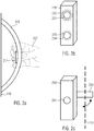
- FIG. 2a to 2c various embodiments of the handle and the button are shown.
- a handle 210 is shown on a protective element 110.
- the handle 210 has on a protective element 110 side facing (in contrast to in Fig. 1 illustrated embodiment) a single button as a button 211 on.
- This button can be configured as a dead man's device, so that the movement of the protective element 110, to which the button is attached, is only possible if the button 211 is also actuated. If the button is released, the movement of the protective element can be completely blocked.
- the arrangement of the button on the back or the protective element 110 facing side of the handle can protect the button from unwanted environmental influences. Furthermore, undesired actuation by an operator bumping against the handle can be avoided, while at the same time good accessibility of the stylus when grasping the handle in the usual manner (represented here by the hand 212) is achieved.
- the handle 220 includes a button as in FIG Fig. 1 two buttons 221 and 223.
- One of these buttons may be provided for releasing the movement of the protective element, not shown here, whereas the other is designed to block the movement of the protective element.
- one of the buttons (for example, 221) allows the opening of the protective element when actuated, whereas the operation of the further button (223 in this case) allows the re-closing and then re-commissioning of the labeling machine.
- each button may be assigned a light element, for example an LED.
- a light element for example an LED.
- this is effected by the collar 222 or 224 around the knob 221 and 223, respectively.
- This ring of light or, more generally, the light element can illuminate when its operation is required for the subsequent movement of a protective element.
- the opening is the only possible movement for the protective element.
- the button 221 is provided for opening the protective element or for releasing the movement necessary for this, the light element 222 can (permanently) light up in the closed state of the protective element.
- the respective light element is only activated and flashes, for example, when a movement without actuation of any button 221 and 223 is attempted or the wrong button is actuated.
- different colors or markings are possible. For example, if the wrong button is pressed, the associated light element can flash red, whereas the light element for the correct button lights green.
- buttons can be provided both analog and electronic.
- the electronic buttons can be connected to a control unit, for example the central control unit of the labeling machine, ie in particular a computer, which in turn controls certain electrically controllable closing mechanisms and depending on the operation of the button controls.
- Fig. 2c shows an embodiment of the handle 230 with an analog button 231, which is shown here as a single button.
- This can, for example, according to the Fig. 2a be designed as Totmann Nurs, and allow movement of the protective element 110 only during its operation.
- This analogue pushbutton 231 is mechanically connected to a closing element 232 such that an actuation of the pushbutton 231 is translated into a movement of the closing element 232 which releases the movement of the protective element at least when the pushbutton 231 is actuated.
- a closing element 232 Such an analogous design of the probe can be advantageous, since even when the central power supply of the labeling machine is switched off, opening and closing or generally moving of the protective element can be reliably ensured.
Landscapes
- Engineering & Computer Science (AREA)
- General Engineering & Computer Science (AREA)
- Mechanical Engineering (AREA)
- Labeling Devices (AREA)
- Lock And Its Accessories (AREA)
Abstract
Description
- Die vorliegende Erfindung betrifft eine Behälterbehandlungsmaschine zum Behandeln von Behältern, insbesondere Etikettiermaschine zum Etikettieren von Behältern, wie Flaschen in der getränkeverarbeitenden Industrie gemäß dem Oberbegriff des Anspruchs 1.
- Behälterbehandlungsmaschinen, wie beispielsweise Etikettiermaschinen gemäß dem Oberbegriff des Anspruchs 1 sind aus dem Stand der Technik bereits bekannt. So zeigt beispielsweise die
DE 20 2005 005 485 U1 einen Schutztürgriff mit einem Griffteil. Ferner ist hier ein Funktionselement vorgesehen, das als zusätzliches Bauteil mit dem Griffteil verbunden werden kann. - Grundsätzlich ist es auch bekannt, für Schutzelemente von Maschineneinheiten Sicherheitsschalter vorzusehen, mit denen das Schutzelement freigegeben werden kann.
- Diese Schalter sind zumeist am Maschinengerüst oder einer anderen Stelle angebracht, um sicherzustellen, dass ein Bediener, der diese Schalter betätigt, nicht gleichzeitig in bewegliche Teile der Maschine greifen kann.
- Dadurch sind diese Schalter jedoch nur schwer zugänglich. Ist es ferner notwendig, dass ein Bediener nach dem erneuten Schließen eines Schutzelements den Standort wechselt, um das Schutzelement zu verriegeln, besteht ein Sicherheitsrisiko für einen eventuell in der Zwischenzeit das Schutzelement betätigenden anderen Bediener.
- Ausgehend vom bekannten Stand der Technik besteht die zu lösende technische Aufgabe somit darin, eine Behälterbehandlungsmaschine zum Behandeln von Behältern anzugeben, bei der die Vorrichtung zum Ver- und Entriegeln eines Schutzelements ergonomisch günstig zu erreichen ist und gleichzeitig die Sicherheit aller Bediener gewährleistet wird.
- Diese Aufgabe wird erfindungsgemäß durch die Behälterbehandlungsmaschine gemäß Anspruch 1 gelöst. Vorteilhafte Weiterbildungen der Erfindung sind in den Unteransprüchen erfasst.
- Die erfindungsgemäße Behälterbehandlungsmaschine zum Behandeln von Behältern wie Flaschen in der getränkeverarbeitenden Industrie umfasst wenigstens eine Maschineneinheit, die im Betrieb Behälter etikettieren kann, und ein bewegliches Schutzelement, das zumindest einen Teil der Maschineneinheit von der Umgebung trennt, wobei das Schutzelement einen Griff zum Bewegen des Schutzelements umfasst. Die Behälterbehandlungsmaschine ist dadurch gekennzeichnet, dass der Griff einen Taster zum Ver- und/oder Entriegeln umfasst, bei dessen Betätigung die Bewegung des Schutzelements freigegeben und/oder gesperrt werden kann.
- Im Sinne der Erfindung ist unter der Maschineneinheit jegliche Komponente der Behälterbehandlungsmaschine zu verstehen. Darunter fallen bei einer Etikettiermaschine insbesondere drehende Elemente, wie beispielsweise Greiferzylinder oder ein eventuell vorgesehenes Maschinenkarussell. Aber auch linear arbeitende oder sich bewegende Elemente fallen hierunter. Bei anderen Behälterbehandlungsmaschinen können auch drehende Elemente wie ein Karussell, auf dem die Behälter transportiert und behandelt werden, als Maschineneinheit gesehen werden.
- Unter einer Behälterbehandlungsmaschine werden u.a. eine Streckblasmaschine zum Herstellen bzw. Aufblasen von PET-Flaschen, eine Abfüllmaschine zum Abfüllen von Behältern, eine Direktdruckmaschine zum Bedrucken von Behältern, eine Beschichtungsmaschine zum Beschichten von Behältern, eine Reinigungs- bzw. Sterilisationsmaschine zum Reinigen bzw. Sterilisieren von Behältern, Inspektionsmaschinen zum Inspizieren von Behältern, eine Verpackungsmaschine zum Verpacken von Behältern, insbesondere in Umverpackungen (Folie, Karton), ein Transporteur zum Transportieren von Behältern (z.B. Weichen, Einteiler, Transportsterne, Puffer), Palettiermaschinen zum Palettieren von Behältern, Depalletiermaschinen zum Depalettieren von Behältern, Verschließmaschinen zum Verschließen von Behältern und dergleichen verstanden. Dementsprechend kann unter einem Behandeln ein Herstellen, Aufblasen, Bedrucken, Beschichten, Reinigen, Sterilisieren usw. verstanden werden. Im Folgenden wird speziell auf eine Etikettiermaschine Bezug genommen, die Merkmale sind jedoch auch auf die anderen genannten Maschinen übertragbar.
- Die vorgeschlagenen Behälterbehandlungsmaschinen stellen keine abschließende Liste möglicher Maschinen dar. Jedoch erweist sich die vorliegende Erfindung gerade in Kombination mit diesen Behälterbehandlungsmaschinen als besonders vorteilhaft, da hier üblicherweise aufgrund vieler beweglicher Teile und/oder hoher Temperaturen/heißer Komponenten ein erhebliches Verletzungsrisiko für einen Bediener besteht, was einen Maschinenschutz nahezu unumgänglich macht. Die vorliegende Erfindung kann daher in Kombination mit diesen konkreten Maschinen besonders vorteilhaft den Schutz des Bedieners und gleichzeitig die Zugänglichkeit der Komponenten der Maschine gewährleisten.
- Dass das Schutzelement einen Teil der Maschineneinheit von der Umgebung trennt ist so zu verstehen, dass von außerhalb des Schutzelements ein manueller Eingriff in die Maschineneinheit oder den Teil der Maschineneinheit erschwert oder unmöglich ist. So kann beispielsweise das Schutzelement als Kasten oder zumindest als "Umzäunung" gedacht sein, die einen innerhalb des Schutzelements liegenden Raum oder Bereich (also ein von dem Schutzelement eingeschlossenes Volumen) von der Umgebung abtrennt, sodass ein in der Umgebung stehender Bediener nicht in den inneren Bereich eingreifen kann, wenn das Schutzelement geschlossen ist.
- Durch Vorsehen des Tasters zum Ver- und/oder Entriegeln am Griff wird sichergestellt, dass ein Bediener, der das Schutzelement öffnet oder schließt, nicht in die Maschineneinheit eingreift, so dass seine Sicherheit gewährleistet werden kann. Gleichzeitig ist der Griff für den Bediener leichter zu erreichen und eine Verzögerung beim Verriegeln des Schutzelements kann vermieden werden, sodass auch nachfolgende Bediener zu jeder Zeit geschützt sind.
- In einer Ausführungsform ist der Taster auf einer vom Schutzelement wegweisenden Seite des Griffs angeordnet. Er ist so leichter für den Bediener zugänglich und ein versehentliches Nicht-Betätigen kann vermieden werden.
- Ferner kann vorgesehen sein, dass der Taster so angeordnet ist, dass er beim Bedienen des Griffs zum Bewegen des Schutzelements gedrückt werden kann. Auch mit dieser Ausführungsform kann vorteilhaft verhindert werden, dass das Bedienen des Tasters vergessen wird oder aus anderen Gründen nicht erfolgt.
- Ferner kann vorgesehen sein, dass der Taster einen Knopf umfasst, bei dessen einmaliger Betätigung die Bewegung des Schutzelements freigegeben werden kann und bei dessen zweiter Betätigung die Bewegung des Schutzelements gesperrt werden kann. Die Bedienung des Tasters ist so möglichst einfach und kann vom Bediener mit geringer Übung erlernt werden.
- In einer alternativen Ausführungsform ist vorgesehen, dass der Taster als Totmanneinrichtung ausgebildet ist, die die Bewegung des Schutzelements nur während ihrer Betätigung freigibt und die Bewegung des Schutzelements sperrt, wenn sie nicht betätigt wird. So kann vermieden werden, dass nach Schließen des Schutzelements dieses versehentlich nicht verriegelt wird, was ansonsten eine Gefahr für nachfolgende Bediener bedeuten kann.
- In einer Ausführungsform ist vorgesehen, dass der Taster als analoger Taster oder als elektronischer Taster bzw. Schalter ausgebildet ist. Ein analoger Taster ist hier als solcher Taster zu verstehen, dessen Betätigung durch mechanische Wechselwirkung mit wenigstens einem anderen Element (beispielsweise einem Verschlusselement, das die Bewegung des Schutzelements sperren kann) ein Freigeben oder Sperren der Bewegung des Schutzelements bewirkt. Ein elektronischer Taster bzw. Schalter hingegen ist ein solcher Schalter, der zumindest in Wechselwirkung mit einer elektronischen Steuereinheit (beispielsweise einem Computer) Teile des Schutzelements und/oder der Etikettiermaschine ansteuert und ihre Bewegung freigibt oder entriegelt. Eine mechanische Wechselwirkung zwischen dem Taster bzw. Schalter und diesen Elementen ist in diesem Fall nicht notwendig.
- Weiterhin kann vorgesehen sein, dass dem Taster ein Lichtelement, beispielsweise eine oder mehrere LEDs zugeordnet ist, das ein optisches Signal ausgeben kann, wenn eine Bewegung des Schutzelements ohne Betätigung des Tasters zu bewegen versucht wird. Ein Bediener, der das Schutzelement ohne Betätigen des Tasters versucht, wird nicht erfolgreich sein. Um die Fehlersuche zu verkürzen, kann das optische Signal dem Bediener vorteilhaft mitteilen, dass der Taster zu betätigen ist.
- Weiterhin kann vorgesehen sein, dass das Schutzelement als Schutztür mit einem oder mehreren Türflügeln oder als Hebeschutzsegment ausgebildet ist. Das Hebeschutzsegment ist ein solches Schutzelement, dessen Bewegung zum wesentlichen Teil oder vollständig in vertikaler Richtung erfolgt. Dies schließt auch eine Kippbewegung um eine horizontale Kippachse mit ein, bei der ein solches Schutzelement zumindest teilweise in vertikaler Richtung bewegt wird. Diese Ausführungsformen können je nach dem für die Etikettiermaschine zur Verfügung stehenden Platz vorteilhaft genutzt werden.
- Ferner kann vorgesehen sein, dass der Taster einen zweiten Knopf umfasst, bei dessen Betätigung der Betrieb der Etikettiermaschine freigegeben werden kann. Während ein erster Knopf gemäß beispielsweise einer der obigen Ausführungsformen das Sperren und Freigeben der Bewegung auf geeignete Art steuern kann, kann dieser Knopf als zusätzliche Sicherheitsmaßnahme genutzt werden, um die Inbetriebnahme der Maschine erst nach einer Prüfung, ob sich Personen im Bereich des Schutzelements aufhalten, zu ermöglichen.
- In einer Weiterbildung dieser Ausführungsform ist der Taster so ausgebildet, dass der zweite Knopf nur bei geschlossenem Schutzelement zum Freigeben des Betriebs der Etikettiermaschine betätigt werden kann. So kann verhindert werden, dass der Betrieb versehentlich bei noch geöffnetem Schutzelement freigegeben wird, womit die Sicherheit weiterer Personen und des Bedieners erhöht werden kann.
-
- Fig. 1
- zeigt schematisch eine Etikettiermaschine mit einem Schutzelement gemäß einer Ausführungsform
- Fig. 2a-c
- zeigen Ausführungsformen verschiedener Griffe mit Tastern
- In
Fig. 1 ist eine Etikettiermaschine 100 gemäß einer Ausführungsform der Erfindung dargestellt. In der hier dargestellten Ausführungsform umfasst die Etikettiermaschine ein Karussell 101 an dessen Peripherie mehrere Behälteraufnahmen 150 vorgesehen sind, in denen Behälter eingespannt werden können. Bei Drehung des Karussells 101 gelangen die Behälter so nach und nach zu dem Etikettieraggregat 140, an dem sie zumindest mit Hilfe des Zylinders 141 mit einem Etikett beaufschlagt werden. Solche Ausführungsformen von Etikettiermaschinen sind dem Fachmann hinlänglich bekannt. - Dem Fachmann ist auch bekannt, dass das Aufbringen der Etiketten beispielsweise mit Hilfe von selbstklebenden Etiketten (von Endlosrollen oder bereits gestückelt in Magazinen vorliegend) erfolgen kann oder hierfür auch Kaltleim- oder Heißleimetiketten zum Einsatz kommen, die zunächst gegebenenfalls zurecht geschnitten und anschließend mit Leim beaufschlagt werden, bevor sie auf den Behälter appliziert werden.
- Die Ausführungsform der Etikettiermaschine als ein Karussell umfassend ist nicht zwingend. So kann auch eine Ausführungsform vorgesehen sein, in der die Etikettiermaschine als linear arbeitende Maschine ausgebildet ist. Ferner muss nicht nur ein Etikettieraggregat 140 an der Peripherie bzw. entlang der Etikettiermaschine vorgesehen sein, sondern es können auch mehrere Etikettieraggregate, die gegebenenfalls auch unterschiedliche Etiketten auf die Behälter applizieren können, vorgesehen sein.
- Ferner umfasst die Etikettiermaschine, in der hier dargestellten Ausführungsform insbesondere das Karussell, ein Schutzelement 110. Dieses Schutzelement 110 ist in der hier dargestellten Ausführungsform als Tür ausgebildet, wobei die Tür insbesondere als Türflügel ausgebildet sein kann, der in die Position 111 verschwenkbar ist.
- Dieser Türflügel umfasst einen Griff 130, der zum Bewegen des Türflügels bzw. allgemeiner des Schutzelements vorgesehen ist. Dazu kann der Griff 130 über Verbindungselemente 133 (auch nur ein Verbindungselement oder mehr als zwei Verbindungselemente sind hier denkbar) mit dem Schutzelement verbunden sein, sodass ein Bediener, der in geeigneter Weise den Griff betätigt bzw. an ihm zieht oder ihn drückt, das Schutzelement bewegen kann. In der hier dargestellten Ausführungsform kann ein Ziehen an dem Griff 130 also zum Öffnen der Tür führen, wohingegen ein Drücken des Griffs bei geöffneter Tür zum Schließen derselben führt.
- Der Griff 130 umfasst erfindungsgemäß wenigstens einen Taster (auch Schalter genannt) 131 bzw. 132, mit dem bei Betätigung die Bewegung des Schutzelements freigegeben und/oder gesperrt werden kann. In der hier dargestellten Ausführungsform sind dabei zwei Knöpfe 131 und 132 vorgesehen, die zusammen den erfindungsgemäßen Taster bilden. Einer dieser Knöpfe kann bei Betätigung das Öffnen des Schutzelements derart ermöglichen, dass eine Bewegung aus dem geschlossenen Zustand heraus freigegeben wird. Der andere Knopf kann in dieser Ausführungsform das Schließen der geöffneten Tür ermöglichen oder bei Betätigung die Bewegung des Schutzelements sperren.
- Alternativ oder zusätzlich kann auch vorgesehen sein, dass einer der Knöpfe, beispielsweise der Knopf 131, das Sperren und Freigeben der Bewegung des Schutzelements ermöglicht und der zweite Knopf (z.B. 132) zum Quittieren vorgesehen ist. In einer solchen Ausführungsform kann der Bediener das Schutzelement durch Betätigen des Knopfes 131 öffnen und schließen. Während das Schutzelement geöffnet ist, ist bevorzugt überhaupt kein Betrieb der Maschine möglich. Nachdem der Bediener das Schutzelement (beispielsweise unter Betätigung des Knopfes 131) geschlossen hat, kann vorgesehen sein, dass der Betrieb der Maschine dennoch nicht unmittelbar freigegeben wird. Vielmehr kann ein Quittieren, bzw. Bestätigen des Bedieners durch Drücken des zweiten Knopfes 132 als notwendiges Signal für das Wiederanfahren der Maschine vorgesehen sein, sodass der Bediener sich bevorzugt vor dem Quittieren über den Knopf 132 vergewissert, ob sich keine weiteren Personen im Bereich der Etikettiermaschine oder gar innerhalb des Schutzelements aufhalten und erst anschließend durch Betätigen des Knopfes 132 den Betrieb der Etikettiermaschine freigibt.
- Ein solcher Knopf zum Quittieren oder Bestätigen, dass die Etikettiermaschine wieder in Betrieb genommen werden kann, kann auch zusätzlich zu den hier beschriebenen Ausführungsformen als "dritter" Knopf oder Schalter vorgesehen sein, wobei ein erster (und zweiter) Knopf für das Freigeben und Sperren der Bewegung des Schutzelements genutzt werden können.
- Während das Schutzelement in der in
Fig. 1 dargestellten Ausführungsform als Türflügel oder allgemeine Tür ausgebildet ist, kann auch vorgesehen sein, dass das Schutzelement im Sinne einer Haube ausgebildet ist und seine Bewegung zumindest zum Teil in einer vertikalen Richtung erfolgt. So sind auch Ausführungsformen denkbar, bei denen an der Peripherie des Karussells 101 ein Schutzelement 110 angeordnet ist, das nach oben oder nach unten, im Wesentlichen parallel zur Rotationsachse des Karussells, verschiebbar ist. Solche Ausführungsformen können genutzt werden, wenn der in der Ebene zur Verfügung stehende Platz zu gering ist, um das Öffnen von Türen zu ermöglichen. - In einem solchen Fall ist die in
Fig. 1 dargestellte Anordnung des Griffs daher gegebenenfalls nicht vorteilhaft, da sie vom Bediener nicht in ergonomischer Weise derart genutzt werden kann, dass das vorgesehene Hebeschutzsegment angehoben werden kann. Im Falle des Vorsehens des Schutzelements 110 als Hebeschutzsegment kann der Griff bevorzugt quer, also bezüglich der inFig. 1 dargestellten Ausführungsform um 90° gekippt angeordnet sein. - Auch die Ausbildung des Griffs 130 als Quader, wie schematisch in
Fig. 1 dargestellt, ist nicht zwingend und auch nicht beschränkend zu verstehen. Hier können sämtliche Ausführungsformen, auch ergonomisch besser geeignete zum Einsatz kommen. - Um allgemein ein Abrutschen vom Griff bei der Bewegung des Schutzelements zu verhindern und damit das Verletzungsrisiko eines Bedieners zu reduzieren, kann der Griff mit einer Antirutschbeschichtung ausgebildet sein. Besonders vorteilhaft ist es, wenn auch der Taster mit einer solchen Beschichtung versehen ist.
- In
Fig. 2a bis 2c sind verschiedene Ausführungsformen des Griffs und des Tasters dargestellt. - In
Fig. 2a ist ein Griff 210 an einem Schutzelement 110 dargestellt. Der Griff 210 weist auf einer dem Schutzelement 110 zugewandten Seite (im Gegensatz zur inFig. 1 dargestellten Ausführungsform) einen einzigen Knopf als Taster 211 auf. Dieser Taster kann als Totmanneinrichtung ausgebildet sein, sodass die Bewegung des Schutzelements 110, an dem der Taster befestigt ist, nur dann möglich ist, wenn der Taster 211 auch betätigt wird. Wird der Taster losgelassen, kann die Bewegung des Schutzelements vollständig gesperrt sein. Die Anordnung des Tasters auf der Rückseite bzw. der dem Schutzelement 110 zugewandten Seite des Griffs kann den Taster vor unerwünschten Umwelteinflüssen schützen. Ferner kann ein unerwünschtes Betätigen durch einen gegen den Griff stoßenden Bediener vermieden werden, wohingegen gleichzeitig eine gute Erreichbarkeit des Tasters beim Umgreifen des Griffs in üblicher Manier (hier dargestellt durch die Hand 212) erreicht wird. - In der Ausführungsform in
Fig. 2b umfasst der Griff 220 als Taster wie inFig. 1 zwei Knöpfe 221 und 223. Einer dieser Knöpfe kann zum Freigeben der Bewegung des hier nicht dargestellten Schutzelements vorgesehen sein, wohingegen der andere zum Sperren der Bewegung des Schutzelements ausgebildet ist. Alternativ kann auch vorgesehen sein, dass einer der Knöpfe (beispielsweise 221) bei dessen Betätigung das Öffnen des Schutzelements erlaubt, wohingegen die Betätigung des weiteren Knopfes (223 in diesem Fall) das erneute Schließen und anschließende wieder Inbetriebnehmen der Etikettiermaschine ermöglicht. - Um dem Bediener die Auswahl der richtigen Knöpfe zu erleichtern, kann jedem Knopf ein Lichtelement, beispielsweise eine LED zugeordnet sein. In der in
Fig. 2b dargestellten Ausführungsform wird dies durch den Kranz 222 bzw. 224 rund um den Knopf 221 bzw. 223 bewirkt. Dieser Lichtkranz oder allgemeiner das Lichtelement kann aufleuchten, wenn für die anschließende Bewegung eines Schutzelements dessen Betätigung erforderlich ist. Befindet sich das Schutzelement beispielsweise im geschlossenen Zustand, so ist das Öffnen die einzig mögliche Bewegung für das Schutzelement. Ist der Knopf 221 für das Öffnen des Schutzelements bzw. zum Freigeben der dafür notwendigen Bewegung vorgesehen, kann im geschlossenen Zustand des Schutzelements das Lichtelement 222 (permanent) aufleuchten. Ferner oder alternativ kann vorgesehen sein, dass das jeweilige Lichtelement nur dann aktiviert wird und beispielsweise aufblinkt, wenn eine Bewegung ohne Betätigung irgendeines Knopfes 221 und 223 versucht wird oder der falsche Knopf betätigt wird. Ferner sind unterschiedliche Farben bzw. Kennzeichnungen möglich. Wird beispielsweise der falsche Knopf betätigt, kann das zugehörige Lichtelement rot aufblinken, wohingegen das Lichtelement für den jeweils korrekten Knopf grün leuchtet. - Auch andere Farbgebungen oder Signalmuster sind hier denkbar.
- Die in
Fig. 2a und 2b dargestellten Ausführungsformen von Tastern können sowohl analog als auch elektronisch vorgesehen sein. Die elektronischen Taster können zum Zwecke der Steuerung des Freigebens oder des Sperrens der Bewegung des Schutzelements 110 mit einer Steuereinheit, beispielsweise der zentralen Steuereinheit der Etikettiermaschine, also insbesondere einem Computer verbunden sein, der wiederum bestimmte elektrisch steuerbare Schließmechanismen kontrolliert und abhängig von der Betätigung des Tasters steuert. -
Fig. 2c zeigt eine Ausführungsform des Griffs 230 mit einem analogen Taster 231, der hier als einzelner Knopf dargestellt ist. Dieser kann beispielsweise entsprechend derFig. 2a als Totmanneinrichtung ausgebildet sein und eine Bewegung des Schutzelements 110 lediglich während seiner Betätigung ermöglichen. - Dieser analoge Taster 231 ist mit einem Verschließelement 232 mechanisch derart verbunden, dass eine Betätigung des Tasters 231 in eine Bewegung des Verschließelements 232 übersetzt wird, das zumindest bei der Betätigung des Tasters 231 die Bewegung des Schutzelements freigibt. Eine solche analoge Ausführung des Tasters kann vorteilhaft sein, da so selbst bei abgeschalteter zentraler Stromversorgung der Etikettiermaschine ein Öffnen und Schließen bzw. allgemein Bewegen des Schutzelements sicher gewährleistet werden kann.
Claims (10)
- Behälterbehandlungsmaschine zum Behandeln von Behältern, insbesondere Etikettiermaschine zum Etikettieren von Behältern, wie Flaschen in der getränkeverarbeitenden Industrie, mit wenigstens einer Maschineneinheit, die im Betrieb Behälter behandeln, insbesondere etikettieren, kann, und einem beweglichen Schutzelement, das zumindest einen Teil der Maschineneinheit von der Umgebung trennt, wobei das Schutzelement einen Griff zum Bewegen des Schutzelements umfasst, dadurch gekennzeichnet, dass der Griff einen Taster zum Ver- und/oder Entriegeln umfasst, bei dessen Betätigung die Bewegung des Schutzelements freigegeben und/oder gesperrt werden kann.
- Behälterbehandlungsmaschine nach Anspruch 1, wobei der Taster auf einer vom Schutzelement wegweisenden Seite des Griffs angeordnet ist.
- Behälterbehandlungsmaschine nach Anspruch 1 oder 2, wobei der Taster so angeordnet ist, dass er beim Bedienen des Griffs zum Bewegen des Schutzelements gedrückt werden kann.
- Behälterbehandlungsmaschine nach einem der Ansprüche 1 bis 3, wobei der Taster einen Knopf umfasst, bei dessen einmaliger Betätigung die Bewegung des Schutzelements freigegeben werden kann und bei dessen zweiter Betätigung die Bewegung des Schutzelements gesperrt werden kann.
- Behälterbehandlungsmaschine nach einem der Ansprüche 1 bis 3, wobei der Taster als Totmanneinrichtung ausgebildet ist, die die Bewegung des Schutzelements nur während ihrer Betätigung freigibt und die Bewegung des Schutzelements sperrt, wenn sie nicht betätigt wird.
- Behälterbehandlungsmaschine nach einem der Ansprüche 1 bis 5, wobei der Taster als analoger Taster oder als elektronischer Taster ausgebildet ist.
- Behälterbehandlungsmaschine nach einem der Ansprüche 1 bis 6, wobei dem Taster ein Lichtelement, beispielsweise eine oder mehrere LEDs zugeordnet ist, das ein optisches Signal ausgeben kann, wenn eine Bewegung des Schutzelements ohne Betätigung des Tasters versucht wird.
- Behälterbehandlungsmaschine nach einem der Ansprüche 1 bis 7, wobei das Schutzelement als Schutztür mit einem oder mehreren Türflügen oder als Hebeschutzsegment ausgebildet ist.
- Behälterbehandlungsmaschine nach einem der Ansprüche 1 bis 8, wobei der Taster einen zweiten Knopf umfasst, bei dessen Betätigung der Betrieb der Behälterbehandlungsmaschine freigegeben werden kann.
- Behälterbehandlungsmaschine nach Anspruch 9, wobei der Taster so ausgebildet ist, dass der zweite Knopf nur bei geschlossenem Schutzelement zum Freigeben des Betriebs der Behälterbehandlungsmaschine betätigt werden kann.
Applications Claiming Priority (1)
| Application Number | Priority Date | Filing Date | Title |
|---|---|---|---|
| DE202017105331.8U DE202017105331U1 (de) | 2017-09-05 | 2017-09-05 | Etikettiermaschine zum Etikettieren von Behältern |
Publications (2)
| Publication Number | Publication Date |
|---|---|
| EP3450818A1 true EP3450818A1 (de) | 2019-03-06 |
| EP3450818B1 EP3450818B1 (de) | 2021-06-23 |
Family
ID=62148142
Family Applications (1)
| Application Number | Title | Priority Date | Filing Date |
|---|---|---|---|
| EP18171412.2A Active EP3450818B1 (de) | 2017-09-05 | 2018-05-09 | Etikettiermaschine zum etikettieren von behältern |
Country Status (4)
| Country | Link |
|---|---|
| US (1) | US10710763B2 (de) |
| EP (1) | EP3450818B1 (de) |
| CN (1) | CN109421979A (de) |
| DE (1) | DE202017105331U1 (de) |
Citations (3)
| Publication number | Priority date | Publication date | Assignee | Title |
|---|---|---|---|---|
| DE9300424U1 (de) * | 1993-01-14 | 1993-03-11 | MAHO AG, 8962 Pfronten | Türe für Schutzkabinen |
| DE202010000032U1 (de) * | 2010-01-13 | 2011-03-10 | Krones Ag | Verriegelungsvorrichtung und Sicherungseinrichtung für einen Arbeitsbereich einer Maschine |
| DE102013001546A1 (de) * | 2013-01-30 | 2014-07-31 | Euchner Gmbh + Co. Kg | Vorrichtung zum lösbaren Arretieren eines vorgebbaren Zustandes einer Einrichtung sowie Sicherheitsschalter mit einer solchen Vorrichtung |
Family Cites Families (21)
| Publication number | Priority date | Publication date | Assignee | Title |
|---|---|---|---|---|
| NL6906618A (de) * | 1968-10-16 | 1970-04-20 | ||
| CN2044411U (zh) * | 1987-12-19 | 1989-09-20 | 昆明市机器厂 | 用于香烟卷接机组的电气控制设备 |
| DE3837218A1 (de) * | 1988-11-02 | 1990-05-03 | Elektronik Geraetewerk Gmbh | Kriech- und drehbewegungsueberwachung bei schutzeinrichtung mit normaler oder erhoehter sicherheit typ ebud-00 (...99) |
| DE19809246A1 (de) * | 1998-03-05 | 1999-09-09 | Focke & Co | Maschine, insbesondere Verpackungsmaschine, mit Verkleidung |
| DE10141835C2 (de) * | 2001-08-27 | 2003-09-04 | Siemens Ag | Vorrichtung zum Verriegeln von wenigstens zwei Schutztüren einer Industriemaschine |
| DE10146828A1 (de) * | 2001-09-18 | 2003-04-24 | Euchner Gmbh & Co | Zuhaltesystem eines Sicherheitsschalters mit einem Lesekopf und einem Betätiger |
| CN2564500Y (zh) * | 2002-04-24 | 2003-08-06 | 白彦扩 | 真空贮藏装置 |
| CN2762988Y (zh) * | 2005-01-26 | 2006-03-08 | 宁波市大江工具有限公司 | 复合锯锯片保护罩自锁紧装置 |
| DE202005005485U1 (de) | 2005-04-07 | 2005-07-07 | steute Schaltgeräte GmbH & Co. KG | Schutztürgriff |
| CN2836283Y (zh) * | 2005-07-14 | 2006-11-08 | 杭州电器开关有限公司 | 铠装中置式交流金属封闭开关设备 |
| CN201124271Y (zh) * | 2007-12-19 | 2008-10-01 | 王骥 | 切割机防护罩自锁装置 |
| CN201651510U (zh) * | 2010-02-10 | 2010-11-24 | 河南理工大学 | 阀门电动装置二级转矩控制开关机构 |
| DE102013205398A1 (de) * | 2013-03-27 | 2014-10-02 | Krones Ag | Rundläufermaschine zur Behälterbehandlung mit Drehgeber |
| DE102013206682A1 (de) * | 2013-04-15 | 2014-10-16 | Krones Ag | Behandlungsmaschine für Behälter |
| DE102013206679A1 (de) * | 2013-04-15 | 2014-10-16 | Krones Ag | Behandlungsmaschine für Behälter |
| DE102013212125A1 (de) * | 2013-06-25 | 2015-01-08 | Krones Aktiengesellschaft | Maschinenschutzeinrichtung |
| CN203814578U (zh) * | 2014-01-28 | 2014-09-10 | 陕西天洋智能科技有限公司 | 碎烟梗烟片精选成套设备 |
| CN104575922B (zh) * | 2014-12-29 | 2017-01-04 | 江苏天港箱柜有限公司 | 拼装式变压器柜 |
| CN206020169U (zh) * | 2016-08-26 | 2017-03-15 | 六和铸造工业(昆山)有限公司 | 一种万能试验机安全防护装置 |
| CN106337268A (zh) * | 2016-09-11 | 2017-01-18 | 浙江大学 | 一种立式分流烘干机 |
| CN207255123U (zh) * | 2017-08-15 | 2018-04-20 | 常国香 | 一种桥梁用钢筋切割装置 |
-
2017
- 2017-09-05 DE DE202017105331.8U patent/DE202017105331U1/de active Active
-
2018
- 2018-05-09 EP EP18171412.2A patent/EP3450818B1/de active Active
- 2018-08-03 US US16/054,798 patent/US10710763B2/en active Active
- 2018-08-16 CN CN201810931566.4A patent/CN109421979A/zh active Pending
Patent Citations (3)
| Publication number | Priority date | Publication date | Assignee | Title |
|---|---|---|---|---|
| DE9300424U1 (de) * | 1993-01-14 | 1993-03-11 | MAHO AG, 8962 Pfronten | Türe für Schutzkabinen |
| DE202010000032U1 (de) * | 2010-01-13 | 2011-03-10 | Krones Ag | Verriegelungsvorrichtung und Sicherungseinrichtung für einen Arbeitsbereich einer Maschine |
| DE102013001546A1 (de) * | 2013-01-30 | 2014-07-31 | Euchner Gmbh + Co. Kg | Vorrichtung zum lösbaren Arretieren eines vorgebbaren Zustandes einer Einrichtung sowie Sicherheitsschalter mit einer solchen Vorrichtung |
Also Published As
| Publication number | Publication date |
|---|---|
| CN109421979A (zh) | 2019-03-05 |
| US10710763B2 (en) | 2020-07-14 |
| US20190071206A1 (en) | 2019-03-07 |
| DE202017105331U1 (de) | 2018-12-06 |
| EP3450818B1 (de) | 2021-06-23 |
Similar Documents
| Publication | Publication Date | Title |
|---|---|---|
| EP2345835B1 (de) | Verriegelungsvorrichtung und Sicherungseinrichtung für einen Arbeitsbereich einer Maschine | |
| DE202010018582U1 (de) | Anlage zur Herstellung von Behältern mit einziehbarem Transferrad | |
| DE102019003317A1 (de) | Vorrichtung zur sterilen Übergabe von Gut zwischen einem Behälter und einem Isolator | |
| DE2013574C3 (de) | Elektromagnetische Zentralver- und Entriegelungseinrichtung für die Türverschlüsse eines Kraftfahrzeuges | |
| DE102010027907A1 (de) | Vorrichtung und Verfahren zum Handhaben eines Behälterproduktes | |
| DE2804613A1 (de) | Verriegelbares tuerschloss fuer kraftfahrzeuge | |
| EP2818786B1 (de) | Maschinenschutzeinrichtung | |
| EP3450818B1 (de) | Etikettiermaschine zum etikettieren von behältern | |
| EP0940343B1 (de) | Maschine, insbesondere Verpackungsmaschine, mit Verkleidung | |
| DE4336199A1 (de) | Greifer für eine Einrichtung zur Entnahme von oben offenen, gestapelten Kästen | |
| DE102012002899A1 (de) | Vorrichtung zum Wechseln des Oberwerkzeugs einer Stanzmaschine | |
| DE10054475A1 (de) | Vorrichtung zum Behandeln von Behältern, insbesondere von KEGs | |
| DE2947996C3 (de) | Sicherheitsvorrichtung für Mikrowellen-Kocheinrichtungen | |
| EP1267022B1 (de) | Notverriegelungseinrichtung | |
| DE556635C (de) | Sicherheitsverschluss fuer einen durch einen abhebbaren Deckel o. dgl. verschliessbaren Behaelter, z. B. fuer eine Waschmaschine | |
| EP3893209B1 (de) | Automatisches lager zur lagerung von gegenständen | |
| DE19507992C1 (de) | Sicherheitseinrichtung für eine Druckmaschine | |
| DE29718103U1 (de) | Hub-Kipp-Vorrichtung | |
| DE102018200219B4 (de) | Vorrichtung zur Erfassung der Stellung eines Ventilglieds, Ventilbaueinheit, Abfüllanlage und Verfahren zur Inbetriebnahme einer Abfüllanlage | |
| DE9112245U1 (de) | Vorrichtung zur Anpassung eines Antriebselementes an ein Zuggeschirr für Straßenfahrzeuge | |
| DE19833807C2 (de) | Einrichtung zum Herausheben von Flaschen, insbesondere Bügelflaschen aus Behältern, insbesondere Flaschenkästen | |
| EP1660384B1 (de) | Verschluss mit farbcodierung | |
| AT407768B (de) | Vorrichtung zum aktivieren und desaktivieren einer öffnungs- und/oder schliesseinrichtung für zumindest eine türe | |
| DE1546157C3 (de) | Trommel zur Aufnahme eines Füllgutes | |
| EP3418045A1 (de) | Vorrichtung und verfahren zur bestrahlung von rohreifen mit elektronenstrahlen |
Legal Events
| Date | Code | Title | Description |
|---|---|---|---|
| PUAI | Public reference made under article 153(3) epc to a published international application that has entered the european phase |
Free format text: ORIGINAL CODE: 0009012 |
|
| STAA | Information on the status of an ep patent application or granted ep patent |
Free format text: STATUS: THE APPLICATION HAS BEEN PUBLISHED |
|
| AK | Designated contracting states |
Kind code of ref document: A1 Designated state(s): AL AT BE BG CH CY CZ DE DK EE ES FI FR GB GR HR HU IE IS IT LI LT LU LV MC MK MT NL NO PL PT RO RS SE SI SK SM TR |
|
| AX | Request for extension of the european patent |
Extension state: BA ME |
|
| STAA | Information on the status of an ep patent application or granted ep patent |
Free format text: STATUS: REQUEST FOR EXAMINATION WAS MADE |
|
| 17P | Request for examination filed |
Effective date: 20190814 |
|
| RBV | Designated contracting states (corrected) |
Designated state(s): AL AT BE BG CH CY CZ DE DK EE ES FI FR GB GR HR HU IE IS IT LI LT LU LV MC MK MT NL NO PL PT RO RS SE SI SK SM TR |
|
| GRAP | Despatch of communication of intention to grant a patent |
Free format text: ORIGINAL CODE: EPIDOSNIGR1 |
|
| STAA | Information on the status of an ep patent application or granted ep patent |
Free format text: STATUS: GRANT OF PATENT IS INTENDED |
|
| INTG | Intention to grant announced |
Effective date: 20201207 |
|
| GRAS | Grant fee paid |
Free format text: ORIGINAL CODE: EPIDOSNIGR3 |
|
| GRAA | (expected) grant |
Free format text: ORIGINAL CODE: 0009210 |
|
| STAA | Information on the status of an ep patent application or granted ep patent |
Free format text: STATUS: THE PATENT HAS BEEN GRANTED |
|
| AK | Designated contracting states |
Kind code of ref document: B1 Designated state(s): AL AT BE BG CH CY CZ DE DK EE ES FI FR GB GR HR HU IE IS IT LI LT LU LV MC MK MT NL NO PL PT RO RS SE SI SK SM TR |
|
| REG | Reference to a national code |
Ref country code: GB Ref legal event code: FG4D Free format text: NOT ENGLISH |
|
| REG | Reference to a national code |
Ref country code: CH Ref legal event code: EP |
|
| REG | Reference to a national code |
Ref country code: DE Ref legal event code: R096 Ref document number: 502018005789 Country of ref document: DE Ref country code: AT Ref legal event code: REF Ref document number: 1404599 Country of ref document: AT Kind code of ref document: T Effective date: 20210715 |
|
| REG | Reference to a national code |
Ref country code: IE Ref legal event code: FG4D Free format text: LANGUAGE OF EP DOCUMENT: GERMAN |
|
| REG | Reference to a national code |
Ref country code: LT Ref legal event code: MG9D |
|
| PG25 | Lapsed in a contracting state [announced via postgrant information from national office to epo] |
Ref country code: FI Free format text: LAPSE BECAUSE OF FAILURE TO SUBMIT A TRANSLATION OF THE DESCRIPTION OR TO PAY THE FEE WITHIN THE PRESCRIBED TIME-LIMIT Effective date: 20210623 Ref country code: LT Free format text: LAPSE BECAUSE OF FAILURE TO SUBMIT A TRANSLATION OF THE DESCRIPTION OR TO PAY THE FEE WITHIN THE PRESCRIBED TIME-LIMIT Effective date: 20210623 Ref country code: HR Free format text: LAPSE BECAUSE OF FAILURE TO SUBMIT A TRANSLATION OF THE DESCRIPTION OR TO PAY THE FEE WITHIN THE PRESCRIBED TIME-LIMIT Effective date: 20210623 Ref country code: BG Free format text: LAPSE BECAUSE OF FAILURE TO SUBMIT A TRANSLATION OF THE DESCRIPTION OR TO PAY THE FEE WITHIN THE PRESCRIBED TIME-LIMIT Effective date: 20210923 |
|
| PG25 | Lapsed in a contracting state [announced via postgrant information from national office to epo] |
Ref country code: GR Free format text: LAPSE BECAUSE OF FAILURE TO SUBMIT A TRANSLATION OF THE DESCRIPTION OR TO PAY THE FEE WITHIN THE PRESCRIBED TIME-LIMIT Effective date: 20210924 Ref country code: RS Free format text: LAPSE BECAUSE OF FAILURE TO SUBMIT A TRANSLATION OF THE DESCRIPTION OR TO PAY THE FEE WITHIN THE PRESCRIBED TIME-LIMIT Effective date: 20210623 Ref country code: SE Free format text: LAPSE BECAUSE OF FAILURE TO SUBMIT A TRANSLATION OF THE DESCRIPTION OR TO PAY THE FEE WITHIN THE PRESCRIBED TIME-LIMIT Effective date: 20210623 Ref country code: NO Free format text: LAPSE BECAUSE OF FAILURE TO SUBMIT A TRANSLATION OF THE DESCRIPTION OR TO PAY THE FEE WITHIN THE PRESCRIBED TIME-LIMIT Effective date: 20210923 Ref country code: LV Free format text: LAPSE BECAUSE OF FAILURE TO SUBMIT A TRANSLATION OF THE DESCRIPTION OR TO PAY THE FEE WITHIN THE PRESCRIBED TIME-LIMIT Effective date: 20210623 |
|
| REG | Reference to a national code |
Ref country code: NL Ref legal event code: MP Effective date: 20210623 |
|
| PG25 | Lapsed in a contracting state [announced via postgrant information from national office to epo] |
Ref country code: NL Free format text: LAPSE BECAUSE OF FAILURE TO SUBMIT A TRANSLATION OF THE DESCRIPTION OR TO PAY THE FEE WITHIN THE PRESCRIBED TIME-LIMIT Effective date: 20210623 Ref country code: RO Free format text: LAPSE BECAUSE OF FAILURE TO SUBMIT A TRANSLATION OF THE DESCRIPTION OR TO PAY THE FEE WITHIN THE PRESCRIBED TIME-LIMIT Effective date: 20210623 Ref country code: PT Free format text: LAPSE BECAUSE OF FAILURE TO SUBMIT A TRANSLATION OF THE DESCRIPTION OR TO PAY THE FEE WITHIN THE PRESCRIBED TIME-LIMIT Effective date: 20211025 Ref country code: CZ Free format text: LAPSE BECAUSE OF FAILURE TO SUBMIT A TRANSLATION OF THE DESCRIPTION OR TO PAY THE FEE WITHIN THE PRESCRIBED TIME-LIMIT Effective date: 20210623 Ref country code: EE Free format text: LAPSE BECAUSE OF FAILURE TO SUBMIT A TRANSLATION OF THE DESCRIPTION OR TO PAY THE FEE WITHIN THE PRESCRIBED TIME-LIMIT Effective date: 20210623 Ref country code: ES Free format text: LAPSE BECAUSE OF FAILURE TO SUBMIT A TRANSLATION OF THE DESCRIPTION OR TO PAY THE FEE WITHIN THE PRESCRIBED TIME-LIMIT Effective date: 20210623 Ref country code: SK Free format text: LAPSE BECAUSE OF FAILURE TO SUBMIT A TRANSLATION OF THE DESCRIPTION OR TO PAY THE FEE WITHIN THE PRESCRIBED TIME-LIMIT Effective date: 20210623 Ref country code: SM Free format text: LAPSE BECAUSE OF FAILURE TO SUBMIT A TRANSLATION OF THE DESCRIPTION OR TO PAY THE FEE WITHIN THE PRESCRIBED TIME-LIMIT Effective date: 20210623 |
|
| PG25 | Lapsed in a contracting state [announced via postgrant information from national office to epo] |
Ref country code: PL Free format text: LAPSE BECAUSE OF FAILURE TO SUBMIT A TRANSLATION OF THE DESCRIPTION OR TO PAY THE FEE WITHIN THE PRESCRIBED TIME-LIMIT Effective date: 20210623 |
|
| REG | Reference to a national code |
Ref country code: DE Ref legal event code: R097 Ref document number: 502018005789 Country of ref document: DE |
|
| PG25 | Lapsed in a contracting state [announced via postgrant information from national office to epo] |
Ref country code: DK Free format text: LAPSE BECAUSE OF FAILURE TO SUBMIT A TRANSLATION OF THE DESCRIPTION OR TO PAY THE FEE WITHIN THE PRESCRIBED TIME-LIMIT Effective date: 20210623 |
|
| PLBE | No opposition filed within time limit |
Free format text: ORIGINAL CODE: 0009261 |
|
| STAA | Information on the status of an ep patent application or granted ep patent |
Free format text: STATUS: NO OPPOSITION FILED WITHIN TIME LIMIT |
|
| 26N | No opposition filed |
Effective date: 20220324 |
|
| PG25 | Lapsed in a contracting state [announced via postgrant information from national office to epo] |
Ref country code: AL Free format text: LAPSE BECAUSE OF FAILURE TO SUBMIT A TRANSLATION OF THE DESCRIPTION OR TO PAY THE FEE WITHIN THE PRESCRIBED TIME-LIMIT Effective date: 20210623 |
|
| REG | Reference to a national code |
Ref country code: CH Ref legal event code: PL |
|
| REG | Reference to a national code |
Ref country code: BE Ref legal event code: MM Effective date: 20220531 |
|
| GBPC | Gb: european patent ceased through non-payment of renewal fee |
Effective date: 20220509 |
|
| PG25 | Lapsed in a contracting state [announced via postgrant information from national office to epo] |
Ref country code: MC Free format text: LAPSE BECAUSE OF FAILURE TO SUBMIT A TRANSLATION OF THE DESCRIPTION OR TO PAY THE FEE WITHIN THE PRESCRIBED TIME-LIMIT Effective date: 20210623 Ref country code: LU Free format text: LAPSE BECAUSE OF NON-PAYMENT OF DUE FEES Effective date: 20220509 Ref country code: LI Free format text: LAPSE BECAUSE OF NON-PAYMENT OF DUE FEES Effective date: 20220531 Ref country code: CH Free format text: LAPSE BECAUSE OF NON-PAYMENT OF DUE FEES Effective date: 20220531 |
|
| PG25 | Lapsed in a contracting state [announced via postgrant information from national office to epo] |
Ref country code: IE Free format text: LAPSE BECAUSE OF NON-PAYMENT OF DUE FEES Effective date: 20220509 |
|
| PG25 | Lapsed in a contracting state [announced via postgrant information from national office to epo] |
Ref country code: GB Free format text: LAPSE BECAUSE OF NON-PAYMENT OF DUE FEES Effective date: 20220509 Ref country code: BE Free format text: LAPSE BECAUSE OF NON-PAYMENT OF DUE FEES Effective date: 20220531 |
|
| PG25 | Lapsed in a contracting state [announced via postgrant information from national office to epo] |
Ref country code: HU Free format text: LAPSE BECAUSE OF FAILURE TO SUBMIT A TRANSLATION OF THE DESCRIPTION OR TO PAY THE FEE WITHIN THE PRESCRIBED TIME-LIMIT; INVALID AB INITIO Effective date: 20180509 |
|
| PG25 | Lapsed in a contracting state [announced via postgrant information from national office to epo] |
Ref country code: MK Free format text: LAPSE BECAUSE OF FAILURE TO SUBMIT A TRANSLATION OF THE DESCRIPTION OR TO PAY THE FEE WITHIN THE PRESCRIBED TIME-LIMIT Effective date: 20210623 Ref country code: CY Free format text: LAPSE BECAUSE OF FAILURE TO SUBMIT A TRANSLATION OF THE DESCRIPTION OR TO PAY THE FEE WITHIN THE PRESCRIBED TIME-LIMIT Effective date: 20210623 |
|
| REG | Reference to a national code |
Ref country code: AT Ref legal event code: MM01 Ref document number: 1404599 Country of ref document: AT Kind code of ref document: T Effective date: 20230509 |
|
| PG25 | Lapsed in a contracting state [announced via postgrant information from national office to epo] |
Ref country code: AT Free format text: LAPSE BECAUSE OF NON-PAYMENT OF DUE FEES Effective date: 20230509 |
|
| PG25 | Lapsed in a contracting state [announced via postgrant information from national office to epo] |
Ref country code: AT Free format text: LAPSE BECAUSE OF NON-PAYMENT OF DUE FEES Effective date: 20230509 |
|
| PG25 | Lapsed in a contracting state [announced via postgrant information from national office to epo] |
Ref country code: MT Free format text: LAPSE BECAUSE OF FAILURE TO SUBMIT A TRANSLATION OF THE DESCRIPTION OR TO PAY THE FEE WITHIN THE PRESCRIBED TIME-LIMIT Effective date: 20210623 |
|
| PGFP | Annual fee paid to national office [announced via postgrant information from national office to epo] |
Ref country code: DE Payment date: 20250402 Year of fee payment: 8 |
|
| PGFP | Annual fee paid to national office [announced via postgrant information from national office to epo] |
Ref country code: IT Payment date: 20250422 Year of fee payment: 8 |
|
| PGFP | Annual fee paid to national office [announced via postgrant information from national office to epo] |
Ref country code: FR Payment date: 20250401 Year of fee payment: 8 |
|
| PG25 | Lapsed in a contracting state [announced via postgrant information from national office to epo] |
Ref country code: TR Free format text: LAPSE BECAUSE OF FAILURE TO SUBMIT A TRANSLATION OF THE DESCRIPTION OR TO PAY THE FEE WITHIN THE PRESCRIBED TIME-LIMIT Effective date: 20210623 |
|
| PGFP | Annual fee paid to national office [announced via postgrant information from national office to epo] |
Ref country code: AT Payment date: 20260410 Year of fee payment: 5 |