EP3449042B1 - Metall/metallchalkogenidelektrode mit hoher spezifischer oberfläche - Google Patents
Metall/metallchalkogenidelektrode mit hoher spezifischer oberfläche Download PDFInfo
- Publication number
- EP3449042B1 EP3449042B1 EP17714480.5A EP17714480A EP3449042B1 EP 3449042 B1 EP3449042 B1 EP 3449042B1 EP 17714480 A EP17714480 A EP 17714480A EP 3449042 B1 EP3449042 B1 EP 3449042B1
- Authority
- EP
- European Patent Office
- Prior art keywords
- electrode
- metal
- electrically conductive
- copper
- deposit
- Prior art date
- Legal status (The legal status is an assumption and is not a legal conclusion. Google has not performed a legal analysis and makes no representation as to the accuracy of the status listed.)
- Active
Links
Images


Classifications
-
- C—CHEMISTRY; METALLURGY
- C25—ELECTROLYTIC OR ELECTROPHORETIC PROCESSES; APPARATUS THEREFOR
- C25B—ELECTROLYTIC OR ELECTROPHORETIC PROCESSES FOR THE PRODUCTION OF COMPOUNDS OR NON-METALS; APPARATUS THEREFOR
- C25B1/00—Electrolytic production of inorganic compounds or non-metals
- C25B1/01—Products
- C25B1/02—Hydrogen or oxygen
- C25B1/04—Hydrogen or oxygen by electrolysis of water
-
- C—CHEMISTRY; METALLURGY
- C25—ELECTROLYTIC OR ELECTROPHORETIC PROCESSES; APPARATUS THEREFOR
- C25B—ELECTROLYTIC OR ELECTROPHORETIC PROCESSES FOR THE PRODUCTION OF COMPOUNDS OR NON-METALS; APPARATUS THEREFOR
- C25B11/00—Electrodes; Manufacture thereof not otherwise provided for
- C25B11/04—Electrodes; Manufacture thereof not otherwise provided for characterised by the material
- C25B11/051—Electrodes formed of electrocatalysts on a substrate or carrier
- C25B11/073—Electrodes formed of electrocatalysts on a substrate or carrier characterised by the electrocatalyst material
- C25B11/075—Electrodes formed of electrocatalysts on a substrate or carrier characterised by the electrocatalyst material consisting of a single catalytic element or catalytic compound
- C25B11/077—Electrodes formed of electrocatalysts on a substrate or carrier characterised by the electrocatalyst material consisting of a single catalytic element or catalytic compound the compound being a non-noble metal oxide
-
- C—CHEMISTRY; METALLURGY
- C25—ELECTROLYTIC OR ELECTROPHORETIC PROCESSES; APPARATUS THEREFOR
- C25B—ELECTROLYTIC OR ELECTROPHORETIC PROCESSES FOR THE PRODUCTION OF COMPOUNDS OR NON-METALS; APPARATUS THEREFOR
- C25B11/00—Electrodes; Manufacture thereof not otherwise provided for
- C25B11/04—Electrodes; Manufacture thereof not otherwise provided for characterised by the material
- C25B11/051—Electrodes formed of electrocatalysts on a substrate or carrier
- C25B11/073—Electrodes formed of electrocatalysts on a substrate or carrier characterised by the electrocatalyst material
- C25B11/091—Electrodes formed of electrocatalysts on a substrate or carrier characterised by the electrocatalyst material consisting of at least one catalytic element and at least one catalytic compound; consisting of two or more catalytic elements or catalytic compounds
- C25B11/093—Electrodes formed of electrocatalysts on a substrate or carrier characterised by the electrocatalyst material consisting of at least one catalytic element and at least one catalytic compound; consisting of two or more catalytic elements or catalytic compounds at least one noble metal or noble metal oxide and at least one non-noble metal oxide
-
- C—CHEMISTRY; METALLURGY
- C25—ELECTROLYTIC OR ELECTROPHORETIC PROCESSES; APPARATUS THEREFOR
- C25D—PROCESSES FOR THE ELECTROLYTIC OR ELECTROPHORETIC PRODUCTION OF COATINGS; ELECTROFORMING; APPARATUS THEREFOR
- C25D3/00—Electroplating: Baths therefor
- C25D3/02—Electroplating: Baths therefor from solutions
- C25D3/38—Electroplating: Baths therefor from solutions of copper
-
- C—CHEMISTRY; METALLURGY
- C25—ELECTROLYTIC OR ELECTROPHORETIC PROCESSES; APPARATUS THEREFOR
- C25D—PROCESSES FOR THE ELECTROLYTIC OR ELECTROPHORETIC PRODUCTION OF COATINGS; ELECTROFORMING; APPARATUS THEREFOR
- C25D5/00—Electroplating characterised by the process; Pretreatment or after-treatment of workpieces
- C25D5/48—After-treatment of electroplated surfaces
-
- C—CHEMISTRY; METALLURGY
- C25—ELECTROLYTIC OR ELECTROPHORETIC PROCESSES; APPARATUS THEREFOR
- C25D—PROCESSES FOR THE ELECTROLYTIC OR ELECTROPHORETIC PRODUCTION OF COATINGS; ELECTROFORMING; APPARATUS THEREFOR
- C25D7/00—Electroplating characterised by the article coated
-
- H—ELECTRICITY
- H01—ELECTRIC ELEMENTS
- H01M—PROCESSES OR MEANS, e.g. BATTERIES, FOR THE DIRECT CONVERSION OF CHEMICAL ENERGY INTO ELECTRICAL ENERGY
- H01M4/00—Electrodes
- H01M4/86—Inert electrodes with catalytic activity, e.g. for fuel cells
- H01M4/88—Processes of manufacture
- H01M4/8825—Methods for deposition of the catalytic active composition
- H01M4/8853—Electrodeposition
-
- H—ELECTRICITY
- H01—ELECTRIC ELEMENTS
- H01M—PROCESSES OR MEANS, e.g. BATTERIES, FOR THE DIRECT CONVERSION OF CHEMICAL ENERGY INTO ELECTRICAL ENERGY
- H01M4/00—Electrodes
- H01M4/86—Inert electrodes with catalytic activity, e.g. for fuel cells
- H01M4/90—Selection of catalytic material
- H01M4/9041—Metals or alloys
-
- H—ELECTRICITY
- H01—ELECTRIC ELEMENTS
- H01M—PROCESSES OR MEANS, e.g. BATTERIES, FOR THE DIRECT CONVERSION OF CHEMICAL ENERGY INTO ELECTRICAL ENERGY
- H01M4/00—Electrodes
- H01M4/86—Inert electrodes with catalytic activity, e.g. for fuel cells
- H01M4/90—Selection of catalytic material
- H01M4/9016—Oxides, hydroxides or oxygenated metallic salts
-
- Y—GENERAL TAGGING OF NEW TECHNOLOGICAL DEVELOPMENTS; GENERAL TAGGING OF CROSS-SECTIONAL TECHNOLOGIES SPANNING OVER SEVERAL SECTIONS OF THE IPC; TECHNICAL SUBJECTS COVERED BY FORMER USPC CROSS-REFERENCE ART COLLECTIONS [XRACs] AND DIGESTS
- Y02—TECHNOLOGIES OR APPLICATIONS FOR MITIGATION OR ADAPTATION AGAINST CLIMATE CHANGE
- Y02E—REDUCTION OF GREENHOUSE GAS [GHG] EMISSIONS, RELATED TO ENERGY GENERATION, TRANSMISSION OR DISTRIBUTION
- Y02E60/00—Enabling technologies; Technologies with a potential or indirect contribution to GHG emissions mitigation
- Y02E60/30—Hydrogen technology
- Y02E60/36—Hydrogen production from non-carbon containing sources, e.g. by water electrolysis
-
- Y—GENERAL TAGGING OF NEW TECHNOLOGICAL DEVELOPMENTS; GENERAL TAGGING OF CROSS-SECTIONAL TECHNOLOGIES SPANNING OVER SEVERAL SECTIONS OF THE IPC; TECHNICAL SUBJECTS COVERED BY FORMER USPC CROSS-REFERENCE ART COLLECTIONS [XRACs] AND DIGESTS
- Y02—TECHNOLOGIES OR APPLICATIONS FOR MITIGATION OR ADAPTATION AGAINST CLIMATE CHANGE
- Y02E—REDUCTION OF GREENHOUSE GAS [GHG] EMISSIONS, RELATED TO ENERGY GENERATION, TRANSMISSION OR DISTRIBUTION
- Y02E60/00—Enabling technologies; Technologies with a potential or indirect contribution to GHG emissions mitigation
- Y02E60/30—Hydrogen technology
- Y02E60/50—Fuel cells
Definitions
- the present invention relates to a metal/metal chalcogenide type electrode (in particular metal oxide or sulfide, in particular copper oxide or sulfide) with a high specific surface area and its preparation process, as well as an electrochemical device containing it and its use in particular in electrolysis processes and more particularly in the oxidation of water into dioxygen.
- a metal/metal chalcogenide type electrode in particular metal oxide or sulfide, in particular copper oxide or sulfide
- Oxygen Evolution Reaction OER
- OER Oxygen Evolution Reaction
- An efficient water oxidation system requires the use of catalytic systems with good stability and selectivity but above all allowing the catalysis of the reaction at a high current density and with a low overpotential.
- Such a catalytic system is particularly difficult to obtain because the reaction involves the loss of four protons and four electrons. An efficient transfer of electrons and protons is therefore necessary.
- KR 101 555 532 also describes an electrode for the electrolysis of water based on a metal sulfide, such as molybdenum sulfide, and a promoter such as cobalt or nickel and copper.
- a metal sulfide such as molybdenum sulfide
- a promoter such as cobalt or nickel and copper.
- WO 2015/170987 describes a nanoparticulate anode material, particularly for the oxidation of water to dioxygen, consisting of a metal oxide such as a copper oxide deposited by electrolytic anodization on an amorphous copper surface.
- Khurram et al. (ACS Catal. 2016, 6, 1768-1771 ) describes an electrode for the oxidation of water comprising, as electrocatalyst, a nanostructured copper oxide.
- cupric oxide (CuO) electrodes or cuprous oxide (CuzO) electrodes have been developed for the oxidation of water to dioxygen (Liu et al. 2016 (a) and (b)).
- CuO cupric oxide
- CuzO cuprous oxide
- the results obtained were comparable to those obtained with cobalt-based systems but using a much cheaper material, copper being 5 times cheaper than cobalt.
- these electrodes still suffer from an overpotential that is too high for dioxygen production.
- Such an electrode can be used to catalyze the water oxidation reaction with a high current density and a low overvoltage (typically 10 mA/cm 2 at less than 350 mV overvoltage).
- a high current density and a low overvoltage typically 10 mA/cm 2 at less than 350 mV overvoltage.
- Such an electrode thus surprisingly gives much better results than those obtained in the prior art with for example an electrode consisting of a cobalt phosphate deposit on a conductive electrode (1 mA/cm 2 at 410 mV overvoltage - Kanan et al. 2008) or using a copper/copper oxide electrode (1 mA/cm 2 at 485 mV - Du et al. 2015)
- electrode means an electronic conductor capable of capturing or releasing electrons.
- the electrode that releases electrons is called an anode.
- the electrode that captures electrons is called a cathode.
- electroconductive support means a support capable of conducting electricity.
- Such a support will be constituted, at least in part and preferably totally, by an electrically conductive material which may be a composite material constituted by several distinct electrically conductive materials.
- the electrically conductive material may be chosen in particular from a metal such as copper, steel, aluminum, zinc or titanium; a metal oxide such as fluorine-doped titanium oxide (FTO) or indium-doped tin oxide (ITO); a metal sulfide such as cadmium sulfide or zinc sulfide; carbon in particular in the form of carbon felt, graphite, vitreous carbon, boron-doped diamond; a semiconductor such as silicon; and a mixture thereof.
- a metal such as copper, steel, aluminum, zinc or titanium
- FTO fluorine-doped titanium oxide
- ITO indium-doped tin oxide
- a metal sulfide such as cadmium sulfide or zinc sulfide
- carbon in particular in the form of
- This support may take any form suitable for use as an electrode, the person skilled in the art being able to determine the form and dimensions of such a support according to the intended use.
- the surface of such a support is covered at least partially by the metal deposit.
- at least 5%, in particular at least 20%, in particular at least 50%, preferably at least 80%, of the surface of the support is covered by the metal deposit.
- the entire surface of the support is covered by the metal deposit.
- the term “deposition of a metal”, also called “metal deposit”, means a deposit of a metal (which may be in the form of a mixture of metals) with an oxidation state of 0. The metal deposit thus forms a metal layer on the surface of the support.
- the metal is advantageously deposited on the support by electrodeposition.
- the metal deposit advantageously has a thickness of between 10 ⁇ m and 2 mm, in particular between 50 ⁇ m and 0.5 mm, preferably between 70 ⁇ m and 300 ⁇ m.
- Such thickness can be measured in particular by measuring a sample section by scanning electron microscopy (SEM).
- the metal deposit has a high specific surface area.
- the metal deposit has more particularly a specific surface area greater than or equal to 1 m 2 /g, in particular greater than or equal to 2 m 2 /g, in particular greater than or equal to 3 m 2 /g, for example greater than or equal to 5 m 2 /g or even greater than or equal to 10 m 2 /g.
- the specific surface area may be between 1 m 2 /g and 500 m 2 /g, for example between 1 m 2 /g and 200 m 2 /g, in particular between 2 m 2 /g and 100 m 2 /g, preferably between 3 m 2 /g and 50 m 2 /g, for example between 5 m 2 /g and 50 m 2 /g or even between 10 m 2 /g and 50 m 2 /g.
- the specific surface area value is indicated per gram of metal deposit.
- Such a specific surface is advantageously determined by the BET method (Brunauer, Emmett and Teller). This BET method will be advantageously applied to a sample of metal deposit obtained by mechanical abrasion using a PVC (polyvinyl chloride) blade 1 mm thick of said metal deposit present on the electrically conductive support.
- the specific surface area can also be expressed in cm 2 /cm 2 geometric .
- the specific surface area value is indicated per cm 2 of electrode and can be advantageously greater than or equal to 5 cm 2 /cm 2 geometric , in particular greater than or equal to 10 cm 2 /cm 2 geometric , in particular greater than or equal to 15 cm 2 /cm 2 geometric .
- the specific surface may be between 5 and 500 cm 2 /cm 2 geometric , for example between 10 and 200 cm 2 /cm 2 geometric , in particular between 15 and 100 cm 2 /cm 2 geometric , preferably between 15 and 50 cm 2 /cm 2 geometric .
- Such a specific surface is advantageously determined by electrochemical measurement (via the Randles-Sevcik equation), more particularly according to the conditions described below in the general considerations of the experimental part.
- the metal deposit will also advantageously have a porous structure.
- the metal deposit will advantageously have a porosity with an average pore size of between 10 ⁇ m and 500 ⁇ m, in particular between 20 ⁇ m and 200 ⁇ m, preferably between 30 ⁇ m and 70 ⁇ m.
- the average pore size can be determined using images obtained by scanning electron microscopy or tunneling electron microscopy, more particularly according to the conditions described below in the general considerations of the experimental part.
- the metal deposited on the support is chosen from copper, iron, nickel, zinc, cobalt, manganese, titanium and a mixture thereof, in particular chosen from copper, iron, nickel, zinc and a mixture thereof.
- the metal may more particularly be copper.
- metals may be present in this metal deposit layer, such as gold, silver, lead, ruthenium, iridium or a mixture thereof.
- these other metals will not represent more than 80%, in particular not more than 50% by weight, preferably not more than 30% by weight of the metal deposit layer.
- the surface of this metal deposit (i.e. the external surface of the metal deposit not in contact with the electrically conductive support) is in an oxidized, sulphurized, selenium and/or tellurium form, i.e. the metal on the surface of this metal deposit is in an oxidized, sulphurized, selenium and/or tellurium form.
- oxidized, sulfurized, selene and/or telluric form of a metal M is meant for the purposes of the present invention the chemical forms M x O y , M x S y , M x Se y , M x Te y , and mixtures thereof where x and y represent integers depending on the degree of oxidation of the metal M.
- the oxidized forms can be CuO and CuzO (preferably CuO)
- the sulfurized forms can be CuS and CuzS (preferably CuS)
- the selene forms can be CuSe and CuzSe
- the telluric forms can be CuTe and CuzTe.
- it will be an oxidized and/or sulphide form, in particular oxidized or sulphide.
- it will be the CuO or CuS forms.
- the surface of the metal deposit is in an oxidized and/or sulfurized form, in particular oxidized or sulfurized.
- the thickness of the oxidized, sulphide, selenium and/or tellurium layer on the surface of the metal deposit is not critical. It may be, for example, between 1 nm and 1 ⁇ m, preferably between 10 and 500 nm. In example 1, the oxidized layer has a thickness of approximately 250 nm.
- This thickness can be measured by transmission electron microscopy (TEM) of a section of the electrode made using the focused ion probe technique.
- TEM transmission electron microscopy
- This oxidized, sulfurized, selenium-containing and/or telluric metallic deposit on the surface represents the catalytic system enabling, in particular, the oxidation of water into dioxygen in an electrolysis process.
- the electrically conductive support will be as defined above.
- a support will be constituted, at least in part and preferably totally, by an electrically conductive material which may be a composite material constituted by several distinct electrically conductive materials.
- the electrically conductive material may be chosen in particular from a metal such as copper, steel, aluminum, zinc, titanium; a metal oxide such as fluorine-doped titanium oxide (FTO - Fluorine-doped Tin Oxide in English) or indium-doped tin oxide (ITO - Indium Tin Oxide in English); a metal sulfide such as cadmium sulfide or zinc sulfide; carbon in particular in the form of carbon felt, graphite, vitreous carbon, boron-doped diamond; a semiconductor such as silicon; and a mixture thereof.
- a metal such as copper, steel, aluminum, zinc, titanium
- a metal oxide such as fluorine-doped titanium oxide (FTO - Fluorine-do
- This support may take any shape suitable for use as an electrode, the person skilled in the art being able to determine the shape and dimensions of such a support according to the intended use.
- the surface of such a support is covered at least partially by the metal deposit.
- at least 5%, in particular at least 20%, in particular at least 50%, preferably at least 80%, of the surface of the support is covered by the metal deposit.
- the entire surface of the support is covered by the metal deposit.
- This electrically conductive support will be advantageously cleaned before carrying out the electrodeposition using techniques well known to those skilled in the art.
- the metal deposited on the support will advantageously be chosen from copper, iron, nickel, zinc, cobalt, manganese, titanium and a mixture of these, in particular from copper, iron, nickel, zinc and a mixture of these.
- the metal may more particularly be copper.
- the metal salt will be present in the solution advantageously at a concentration of between 0.1 mM and 10 M, in particular between 1 mM and 1 M.
- metal complexes formed between the ion of the metal to be deposited and one or more organic ligands such as for example porphyrins, amino acids or amines, to introduce the metal ions into the aqueous solution.
- the acid introduced into the aqueous solution may be any acid, whether organic or inorganic. It may be, for example, sulfuric acid, hydrochloric acid, hydrobromic acid, formic acid or acetic acid, in particular sulfuric acid. Preferably, it will not be nitric acid.
- This acid may be present in the acidic aqueous solution advantageously at a concentration of between 0.1 mM and 10 M, in particular of between 10 mM and 3 M.
- the acidic aqueous solution is advantageously prepared using deionized water in order to better control the ionic composition of the solution.
- the electrically conductive support will be totally or partially immersed in the acidic aqueous solution containing the ions of the metal to be deposited depending on whether a deposit on the entire surface or on only part of the surface of the support is desired.
- the entire support, on which the mask has been applied can be immersed in the acidic aqueous solution containing the ions of the metal to be deposited. This mask will be removed from the support after deposition of the metal.
- the electrically conductive support will play the role of cathode, while the second electrode will play the role of anode.
- the second electrode will advantageously be immersed in the acidic aqueous solution containing the ions of the metal to be deposited but may also be immersed in another electrolyte solution electrically connected to the first.
- the nature of the second electrode is not critical. It is just necessary to carry out the electrodeposition by an electrolysis process. It could be, for example, a platinum or titanium electrode.
- the current applied between the electrically conductive support and the second electrode may be alternating or direct. It will advantageously be direct and will preferably have a high current density of between 0.1 mA/cm 2 and 5 A/cm 2 , in particular of between 0.1 mA/cm 2 and 1 mA/cm 2 . Alternatively, a voltage making it possible to generate an equivalent current density may be applied between the electrodes.
- an oxidation reaction will take place at the anode when current is applied.
- the nature of this oxidation reaction is not crucial. It could be, for example, the oxidation of water.
- Electrodeposition thus allows the deposition on the surface of the electrically conductive support of a thin layer of metal with a high specific surface area, the growth of the metal on the surface of the electrically conductive support being done in a dendritic manner.
- the formation of dihydrogen bubbles on the surface of the electrically conductive support thanks to the proton reduction reaction, also allows a porous structure to be given to this layer of metal deposit, thus further increasing this specific surface area.
- the choice of current density will in particular allow the size and number of bubbles formed to be optimized so as to obtain the structure and specific surface area desired for the metal deposit.
- the current will also be applied for a sufficient duration to obtain the desired deposit quantity, in particular to obtain a thickness of said metal deposit layer of between 10 ⁇ m and 2 mm, in particular of between 50 ⁇ m and 0.5 mm, preferably of between 70 ⁇ m and 300 ⁇ m.
- the current may be applied for a duration of between 1 and 3600 s, for example between 15 and 1200 s, in particular of between 30 and 300 s.
- the application duration and current density can be adapted according to the chosen reaction conditions such as the nature and concentration of the metal ions, the acid concentration, etc. in order to obtain the desired metal deposit, in particular with the desired specific surface and thickness.
- Electrodeposition will advantageously be carried out by a galvanostatic method, that is to say by application of a constant current throughout the duration of the deposition.
- the electrically conductive support at least part of the surface of which is covered by a metal deposit, can be removed from the solution in which it was immersed. It must be cleaned, in particular with water (e.g. distilled water), before being dried, in particular under vacuum, or under a flow of an inert gas (argon, nitrogen, helium, etc.).
- water e.g. distilled water
- an inert gas argon, nitrogen, helium, etc.
- the external surface of the metal deposit will be oxidized, sulfurized, selenized and/or tellurated.
- the oxidation step will advantageously be carried out in an atmosphere containing dioxygen (e.g. air) or in the presence of H 2 O, preferably in a atmosphere containing dioxygen (e.g. air).
- the sulfurization step will advantageously be carried out in the presence of elemental sulfur or H 2 S, preferably in the presence of elemental sulfur.
- the selenation step will advantageously be carried out in the presence of elemental selenium or H 2 Se, preferably in the presence of elemental selenium.
- the telluration step will advantageously be carried out in the presence of elemental tellurium or H 2 Te, preferably in the presence of elemental tellurium.
- This oxidation, sulfurization, selenation and/or telluration step will advantageously be carried out at a high temperature, in particular at a temperature between 30 and 700°C, in particular between 50 and 500°C, in particular between 100 and 400°C.
- An annealing step may be carried out following the oxidation, sulfurization, selenation and/or tellurization step.
- This annealing step will advantageously be carried out at a temperature between 50°C and 1000°C, in particular between 100°C and 400°C.
- This annealing step will advantageously be carried out under an inert gas atmosphere (Ar, N2 , He, etc.) or under vacuum.
- This annealing step will advantageously be carried out for a sufficiently long period, in particular for a time between 10 min and 48 h, in particular between 1 and 3 h.
- An additional step of depositing metal oxide on the surface of the metal deposit may possibly be carried out after step (ii). This will thus make it possible to have an additional layer of metal oxide on the surface of the metal deposit.
- the metal oxide will be an oxide of a metal selected from copper, iron, nickel, zinc, cobalt, manganese, titanium and a mixture thereof. Preferably, it will be copper oxide, and more particularly CuO.
- Step (1)
- the solution containing ions of the metal of the metal oxide to be deposited will more particularly be a solution containing a salt of the metal of the metal oxide to be deposited (also called a metal salt), possibly introduced in a hydrated form.
- This metal salt possibly in a hydrated form, may be any salt of said metal.
- copper it may be CuSO 4 , CuCl 2 or Cu(ClO 4 ) 2 or a mixture thereof.
- metal complexes formed between the metal ion of the metal oxide to be deposited and one or more organic ligands such as for example porphyrins, amino acids or amines (eg imidazole, 1,4,8,11-tetraazacyclotetradecane (cyclam) or 1,4,8,11-tetramethyl-1,4,8,11-tetraazacyclotetradecane (Me 4 -cyclam), to introduce the metal ions into the aqueous solution.
- organic ligands eg imidazole, 1,4,8,11-tetraazacyclotetradecane (cyclam) or 1,4,8,11-tetramethyl-1,4,8,11-tetraazacyclotetradecane (Me 4 -cyclam
- copper it could be CuCl 2 complexed with one or more, in particular 1 or 2, organic ligands, preferably nitrogenous such as amines.
- It could in particular be Cu(imidazole) 2 Cl 2 , Cu(cyclam
- the metal salt will be present in the solution advantageously at a concentration of between 0.1 mM and 10 M, in particular between 1 mM and 0.1 M.
- the solution containing ions of the metal of the metal oxide to be deposited may be a solution in water and/or an organic solvent, in particular in water or in a water/organic solvent mixture.
- the solvent used (water and/or organic solvent) will be chosen so as to be able to solubilize the metal salt.
- the organic solvent may be any suitable solvent such as acetonitrile, pyridine, tetrahydrofuran (THF), dimethyl sulfoxide (DMSO) or dimethylformamide (DMF), in particular acetonitrile.
- the water used will preferably be deionized water in order to better control the ionic composition of the solution.
- the solution may also contain a base salt, i.e. a salt that cannot be oxidized or reduced and therefore does not participate in the oxidation-reduction reaction but which allows the current to be conducted.
- a base salt i.e. a salt that cannot be oxidized or reduced and therefore does not participate in the oxidation-reduction reaction but which allows the current to be conducted.
- the nature of the base salt is therefore not critical. It should be chosen so that it is soluble in the solvent used (water and/or organic solvent). This may be TBAPF 6 (tetrabutylammonium hexafluorophosphate) or TBABF 4 (tetrabutylammonium tetrafluoroborate).
- the electrically conductive support will be totally or partially immersed in the solution containing the ions of the metal of the metal oxide to be deposited depending on the surface of the support to be covered.
- step (2) comprising the two aforementioned phases may be repeated one or more times so as to optimize the deposition of metal oxide and the performance of the electrode obtained.
- step (2) is carried out 1 or 2 times, in particular 2 times.
- the second electrode will advantageously be immersed in the solution containing the ions of the metal of the metal oxide to be deposited but may also be immersed in another electrolyte solution electrically connected to the first.
- the nature of the second electrode is not critical. It is just necessary to carry out the electrodeposition and then the oxidation. It could be, for example, a platinum or titanium electrode.
- an oxidation reaction will take place at the anode when current is applied.
- the nature of this oxidation reaction is not crucial. It could be, for example, the oxidation of water.
- This phase thus allows the electrodeposition of a thin layer of metal on the surface of the metal deposit obtained in step (ii).
- an oxidation reaction will take place at the anode (electroconductive support), namely the oxidation of the metal, for example according to the following reaction in the case of water as the oxygen source with M representing the metal and x representing its oxidation state: M + H 2 O ⁇ MO + 2 e + 2 H + .
- This phase thus allows the oxidation of the thin layer of metal electrodeposited on the surface of the metal deposit obtained in step (ii).
- This step (2) can advantageously be carried out by one or more, in particular 1 or 2, cyclic voltammetry cycles, that is to say by applying a current varying linearly over time.
- the electrically conductive support can be removed from the solution in which it was immersed. It must be cleaned, in particular with water (e.g. distilled water), before being dried, in particular under vacuum, or under a flow of an inert gas (argon, nitrogen, helium, etc.).
- water e.g. distilled water
- an inert gas argon, nitrogen, helium, etc.
- the electrode according to the present invention is an electrode capable of being obtained by the aforementioned method.
- the third subject of the present invention is an electrochemical device comprising an electrode according to the present invention.
- electrochemical device means a device for converting electrical energy into chemical energy (e.g. an electrolysis device) or, conversely, for converting chemical energy into electrical energy (e.g. a fuel cell).
- the electrochemical device according to the present invention will therefore be more particularly an electrolysis device or a fuel cell.
- Such an electrochemical device will comprise a second electrode which may optionally also be an electrode according to the present invention.
- One of the electrodes will act as an anode where oxidation will occur, the other electrode will act as a cathode where reduction will occur.
- Such a device will therefore implement a substance to be oxidized (e.g. H2 in a fuel cell or H2O in an electrolysis device) and a substance to be reduced (e.g. O2 in a fuel cell or H2O or CO2 in an electrolysis device).
- a substance to be oxidized e.g. H2 in a fuel cell or H2O in an electrolysis device
- a substance to be reduced e.g. O2 in a fuel cell or H2O or CO2 in an electrolysis device.
- the redox reaction will be forced, i.e. caused by the applied electric current.
- the redox reaction will be spontaneous, allowing the generation of electrical energy.
- Such devices will notably comprise other elements well known to those skilled in the art in the field of electrochemistry such as one or more other electrodes (in particular a potential reference electrode), a source energy, a membrane, a bottom salt, a device allowing the flow of reagents, a device for collecting the gases formed, etc.
- electrodes in particular a potential reference electrode
- source energy e.g. a source energy
- membrane e.g. a membrane
- a bottom salt e.g., a device for collecting the gases formed, etc.
- a device for collecting the gases formed e.g., a device for collecting the gases formed, etc.
- the person skilled in the art knows perfectly well how to produce and implement such an electrochemical device.
- the electrochemical device according to the present invention will advantageously be an electrolysis device.
- this device will use the electrode according to the present invention as an anode, in particular to oxidize water into dioxygen according to the following reaction: 2H 2 O ⁇ O 2 + 4H + + 4e -
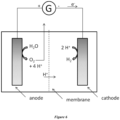
- FIG. 6 An example of a water electrolysis device is shown in Figure 6 .
- the present invention also has as a fourth subject a method of oxidizing water into dioxygen comprising the application of an electric current between an anode and a cathode, the anode being an electrode according to the invention immersed in water or in a fluid containing water.
- immersed in a fluid means that the electrode is at least partially immersed in the fluid.
- the part of the electrode covered by the metal deposit, the surface of which is oxidized, sulfurized, selenized and/or tellurated, must be at least partially immersed in the fluid.
- the anode corresponding to an electrode according to the present invention, will preferably be immersed in water, and more particularly in water having a basic pH (between 7 and 14, preferably between 10 and 14), obtained for example by adding soda.
- the cathode may also be immersed in the same fluid or may be immersed in another fluid. CO2 may be added to this fluid by bubbling or pressurizing the medium. In the case where the anode and the cathode are not immersed in the same fluid, these two fluids may be separated for example by an ion exchange membrane (e.g. protons), osmotic or dialysis membrane in order to allow the passage of charges or solvent molecules from one fluid to the other.
- an ion exchange membrane e.g. protons
- the cathode may be any electrode conventionally used in the art as a cathode and which is well known to those skilled in the art.
- a cathode may be, for example, platinum, cobalt, copper, etc.
- the current applied between the two electrodes will have a potential difference of between 1.2 V and 10 V, in particular between 1.4 V and 4 V.
- an electrode according to the invention makes it possible to carry out this reaction of oxidation of water into dioxygen with an overvoltage of less than 350 mV, or even less than 300 mV, for a current density of 10 mA/cm 2 or even less than 550 mV, which can go at least up to 450 mV, for a current density of 100 mA/cm 2 .
- this reaction can be carried out with an overvoltage of 340 mV or even 290 mV for a current density of 10 mA/cm 2 ; or 530 mV or even 450 mV for a current density of 100 mA/cm 2 .
- the electrode according to the invention thus makes it possible to efficiently carry out the reaction of oxidation of water into dioxygen, while having an inexpensive catalytic system.
- Electrocatalytic measurements and electrolysis experiments are carried out in a two-compartment three-electrode cell, allowing separation of the gas-phase products to the anodic and cathodic compartments using a Bio-Logic SP300 potentiostat.
- An Ag/AgCl reference electrode is placed in the same compartment as the working electrode.
- a platinum counter electrode is placed in a separate compartment connected by a porosity 5 glass frit filled with the electrolytic solution.
- the linear sweep voltammetry result is not compensated for ohmic drop.
- the faradaic efficiency was obtained by comparing the theoretical amount of oxygen produced based on the charge consumed with the amount of oxygen determined by gas chromatography.
- the electroactive surface of the electrodes is measured using an electrode with a geometric surface area of 1 cm 2 immersed in a solution containing 5 mM K 3 [Fe(CN) 6 ] and 0.1 M phosphate buffer pH 7.0.
- the samples used for the BET measurements were obtained by mechanical abrasion using a PVC (polyvinyl chloride) blade 1 mm thick from the metal deposit present on the support.
- Example 1 Preparation of a copper/copper oxide electrode according to the invention on a copper support
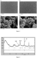
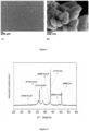
- FIGS 1 A And 1C show SEM images of this electrode and illustrate the porous nanostructures and the large specific surface area of the material.
- the X-ray powder diffractogram of this electrode is shown in Figure 2 and reveals the presence of Cu, Cu 2 O and CuO.
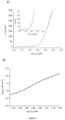
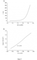
- Linear sweep voltammetry between 1.2V and 2.0V vs ERH (Reversible Hydrogen Electrode) in 1.0M NaOH aqueous solution with a scan rate of 10mV/s is presented in Figure 3A .
- a current density of 10mA.cm -2 was obtained at 340mV overvoltage for the production of dioxygen.
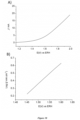
- the Tafel plot of the electrode is shown in Figure 3B .
- the catalytic activity increases linearly from 1.56V to 1.66V vs ERH.
- the slope of the Tafel line was determined in this region to be 38mV.dec -1 .
- the specific surface area determined electrochemically is 19.6 cm 2 /cm 2 geometric .
- the temperature of the assembly is raised to 150 °C at a rate of 15 °C per minute, and the temperature is maintained at 150 °C for 2 minutes.
- the reactor is removed from the furnace and allowed to cool to room temperature while evacuating the reactor (dynamic vacuum).
- the compartment containing the elemental sulfur is disconnected from the reactor containing the electrode and the reactor containing the electrode is reintroduced into the furnace while evacuating (dynamic vacuum - 0.01 mbar).
- the furnace temperature is raised to 150 °C at a rate of 15 °C per minute, and the temperature is maintained at 150 °C for 1 h.
- the electrode is cooled to room temperature under dynamic vacuum and used quickly after its preparation.
- the specific surface area determined electrochemically is 23.0 cm 2 /cm 2 geometric .
- the specific surface area determined by BET is 3.8 m 2 /g.
- Example 3 Measurement of the catalytic activity for the oxidation of water from the Cu/Cu x O y electrode
- Example 4 Measurement of the catalytic activity for the oxidation of water from the Cu/Cu electrode x S y
- Example 5 Durability of the Cu/Cu x O y electrode under catalytic conditions
- 1 cm 2 of a freshly cleaned copper plate is immersed in 20 ml of a 0.2 M CuSO 4 solution, 1.5 M H 2 SO 4 and a current of 0.5 A is applied using a galvanostatic method for a period of 80 s.
- the electrode is then removed from the solution and cleaned with large quantities of distilled water and dried under vacuum (10 mbar).
- the electrode is then transferred to an oven under a static air atmosphere (1 bar). The temperature is raised to 310 °C at a rate of 10 °C per minute, and the temperature is held constant for 1 hour.
- the electrode is cooled to room temperature.
- the electrode thus prepared is then immersed in a solution of Cu(imidazole) 2 Cl 2 (0.2 mM) in an acetonitrile / 3% water (v/v) mixture also containing 0.1 M of TBAPF 6 background salt (tetrabutylammonium hexafluorophosphate).
- TBAPF 6 background salt tetrabutylammonium hexafluorophosphate.
- the electrode is then subjected to two cycles of cyclic voltammetry between -0.5 V and 1 V (vs Ag/AgCl) and a cycle rate of 50 mV/s.
- the electrode thus obtained is removed from the solution and cleaned with large quantities of distilled water and air dried at room temperature.
- This electrode is named Cu/Cu x O y /CuO NP electrode hereafter.
- FIG. 7 shows SEM images of this electrode and illustrate the porous nanostructures and the large specific surface area of the material.
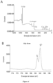
- the X-ray powder diffractogram of this electrode is shown in Figure 8 and reveals the presence of Cu, CuzO and CuO.
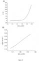
- Linear sweep voltammetry between 1.2V and 2.0V vs ERH (Reversible Hydrogen Electrode) in 1.0M KOH aqueous solution with a scan rate of 10 mV/s is presented in Figure 9A .
- a current density of 10 mA.cm -2 was obtained at 290 mV overpotential for the production of dioxygen.
- the Tafel plot of the electrode is shown in Figure 9B .
- the catalytic activity increases linearly from 1.56V to 1.66V vs ERH.
- the slope of the Tafel line was determined in this region to be 64 mV.dec -1 .
- the specific surface area determined electrochemically is 20.6 cm 2 /cm 2 geometric .
- FIG. 13 shows TEM images of an electrode section taken by focused ion probe:
- STEM-HAADF Scnning Transmission Electron Microscope / High-Angle Annular Dark-Field
- SAED Select Area Electron Diffraction
- STEM-XEDS Sccanning Transmission Electron Microscope / X-ray Energy-Dispersive Spectroscopy
- TBAPF 6 tetrabutylammonium hexafluorophosphate
- TBABF 4 tetrabutylammonium tetrafluoroborate
- Example 7 Preparation of a copper/copper oxide electrode according to the invention on an FTO support
- Example 8 Preparation of a copper/copper oxide electrode according to the invention on a carbon felt support
- Example 9 Preparation of a copper/copper oxide electrode according to the invention on a titanium support
Landscapes
- Chemical & Material Sciences (AREA)
- Engineering & Computer Science (AREA)
- Chemical Kinetics & Catalysis (AREA)
- Electrochemistry (AREA)
- Materials Engineering (AREA)
- Organic Chemistry (AREA)
- Metallurgy (AREA)
- General Chemical & Material Sciences (AREA)
- Inorganic Chemistry (AREA)
- Manufacturing & Machinery (AREA)
- Electrodes For Compound Or Non-Metal Manufacture (AREA)
- Electrolytic Production Of Non-Metals, Compounds, Apparatuses Therefor (AREA)
- Inert Electrodes (AREA)
- Electrolytic Production Of Metals (AREA)
Claims (14)
- Elektrode, umfassend einen elektrisch leitenden Träger, bei dem mindestens ein Teil der Oberfläche mit einer Kupfermetallabscheidung bedeckt ist, wobei die Oberfläche der Abscheidung in oxidierter, sulfidierter, selensierter und/oder tellurierter Form vorliegt und die Abscheidung eine spezifische Oberfläche von über oder gleich 1 m2/g aufweist,wobei die Elektrode durch ein Herstellungsverfahren erhältlich ist, das die folgenden aufeinanderfolgenden Schritte umfasst:(i) Elektroabscheidung von Kupfer auf mindestens einem Teil der Oberfläche eines elektrisch leitenden Trägers, um eine Metallabscheidung des Kupfers auf dem mindestens einen Teil der Oberfläche des elektrisch leitenden Trägers zu bilden, und(ii) Oxidation, Sulfidierung, Selenisierung und/oder Tellurierung der Oberfläche der Metallabscheidung,wobei Schritt (i) in den folgenden aufeinanderfolgenden Schritten durchgeführt wird:(a) zumindest teilweises Eintauchen des elektrisch leitenden Trägers in eine saure wässrige Lösung, die Ionen des abzuscheidenden Kupfers enthält, und(b) Anlegen eines Stroms zwischen dem elektrisch leitenden Träger und einer zweiten Elektrode.
- Elektrode nach Anspruch 1, dadurch gekennzeichnet, dass der elektrisch leitende Träger zumindest teilweise aus einem elektrisch leitenden Material besteht, das aus einem Metall wie Kupfer, Stahl, Aluminium, Zink; einem Metalloxid wie fluordotiertes Titanoxid (FTO) oder indiumdotiertes Zinnoxid (ITO); einem Metallsulfid wie Cadmiumsulfid oder Zinksulfid; Kohlenstoff, insbesondere in Form von Kohlenstofffilz, Graphit, glasartigem Kohlenstoff, bordotiertem Diamant; einem Halbleiter wie Silizium; und einer Mischung davon ausgewählt ist.
- Elektrode nach einem der Ansprüche 1 und 2, dadurch gekennzeichnet, dass die Metallabscheidung eine Dicke zwischen 10 µm und 2 mm, insbesondere zwischen 50 µm und 0,5 mm, vorzugsweise zwischen 70 µm und 300 um, hat.
- Elektrode nach einem der Ansprüche 1 bis 3, dadurch gekennzeichnet, dass die Metallabscheidung eine spezifische Oberfläche zwischen 1 m2/g und 500 m2/g, beispielsweise zwischen 1 m2/g und 200 m2/g, insbesondere zwischen 2 m2/g und 100 m2/g, vorzugsweise zwischen 3 m2/g und 50 m2/g, hat.
- Elektrode nach einem der Ansprüche 1 bis 4, dadurch gekennzeichnet, dass die Metallabscheidung eine poröse Struktur mit einer mittleren Porengröße zwischen 10 µm und 500 um, insbesondere zwischen 20 µm und 200 um, vorzugsweise zwischen 30 µm und 70 um, hat.
- Elektrode nach einem der Ansprüche 1 bis 5, dadurch gekennzeichnet, dass die Oberfläche der Metallabscheidung in einer oxidierten und/oder sulfurierten Form, insbesondere in einer oxidierten oder sulfurierten Form, vorliegt.
- Verfahren zur Herstellung einer Elektrode nach einem der Ansprüche 1 bis 6, das die folgenden aufeinanderfolgenden Schritte umfasst:(i) Elektroabscheidung von Kupfer auf mindestens einem Teil der Oberfläche eines elektrisch leitenden Trägers, um eine Metallabscheidung des Kupfers auf dem mindestens einen Teil der Oberfläche des elektrisch leitenden Trägers zu bilden, und(ii) Oxidation, Sulfidierung, Selenisierung und/oder Tellurierung der Oberfläche der Metallabscheidung,wobei Schritt (i) in den folgenden aufeinanderfolgenden Schritten durchgeführt wird:(c) zumindest teilweises Eintauchen des elektrisch leitenden Trägers in eine saure wässrige Lösung, die Ionen des abzuscheidenden Kupfers enthält, und(d) Anlegen eines Stroms zwischen dem elektrisch leitenden Träger und einer zweiten Elektrode.
- Verfahren nach Anspruch 7, dadurch gekennzeichnet, dass die saure wässrige Lösung, die Ionen des abzuscheidenden Kupfers enthält, eine saure wässrige Lösung ist, die ein wasserlösliches Salz des abzuscheidenden Kupfers enthält, das insbesondere aus CuSO4, CuCl2, Cu (ClO4)2 und einer Mischung davon ausgewählt ist.
- Verfahren nach einem der Ansprüche 7 und 8, dadurch gekennzeichnet, dass der Strom von Schritt (b) eine Stromdichte zwischen 0,1 mA/cm2 und 5 A/cm2, insbesondere zwischen 0,1 mA/cm2 und 1 mA/cm2, hat.
- Verfahren nach einem der Ansprüche 7 bis 9, dadurch gekennzeichnet, dass Schritt (ii) umfasst:- einen Oxidations-, Sulfurierungs-, Selenierungs- und/oder Tellurierungsschritt, der bei einer Temperatur zwischen 30 und 700°C, insbesondere zwischen 50 und 500°C, vor allem zwischen 100 und 400°C durchgeführt wird, wobei der Oxidationsschritt in einer Sauerstoff enthaltenden Atmosphäre oder in Gegenwart von H2O durchgeführt wird, der Sulfurierungsschritt in Gegenwart von elementarem Schwefel oder von H2S durchgeführt wird, der Selenierungsschritt in Gegenwart von elementarem Selen oder von H2Se durchgeführt wird, und der Tellurierungsschritt in Gegenwart von elementarem Tellur oder von H2Te durchgeführt wird, und- gegebenenfalls einen Glühschritt, der bei einer Temperatur zwischen 50°C und 1000°C, vor allem zwischen 100°C und 400°C, in vorteilhafter Weise während einer Zeit zwischen 10 Min und 48 Std., insbesondere zwischen 1 und 3 Std., durchgeführt wird.
- Verfahren nach einem der Ansprüche 7 bis 10, dadurch gekennzeichnet, dass auf Schritt (ii) ein Schritt (iii) folgt, der gemäß den folgenden aufeinanderfolgenden Schritten durchgeführt wird:(1) Eintauchen mindestens des Teils des elektrisch leitenden Trägers, der mit einer Metallabscheidung bedeckt ist, deren äußere Oberfläche oxidiert, sulfidiert, selenisiert und/oder telluriert ist, die in Schritt (ii) erhalten wurde, in eine Lösung, die Kupferionen und in vorteilhafterweise Wasser enthält, und(2) Anlegen eines Potentials zwischen dem elektrisch leitenden Träger und einer zweiten Elektrode, wobei das an den elektrisch leitenden Träger angelegte elektrische Potential zunächst negativ und dann positiv ist,wobei Schritt (iii) ein- oder mehrmals wiederholt werden kann.
- Elektrochemische Vorrichtung, die eine Elektrode nach einem der Ansprüche 1 bis 6 umfasst.
- Elektrochemische Vorrichtung nach Anspruch 12, dadurch gekennzeichnet, dass es sich um eine Elektrolysevorrichtung oder eine Brennstoffzelle handelt.
- Verfahren zur Oxidation von Wasser zu Sauerstoff, umfassend das Anlegen eines elektrischen Stroms zwischen einer Anode und einer Kathode, wobei die Anode eine Elektrode nach einem der Ansprüche 1 bis 6 ist, die in Wasser oder in ein wasserhaltiges Fluid eingetaucht ist, vorteilhafterweise mit einem basischen pH-Wert.
Applications Claiming Priority (2)
| Application Number | Priority Date | Filing Date | Title |
|---|---|---|---|
| FR1653753A FR3050740B1 (fr) | 2016-04-27 | 2016-04-27 | Electrode metal / chalcogenure metallique a haute surface specifique |
| PCT/EP2017/057756 WO2017186454A1 (fr) | 2016-04-27 | 2017-03-31 | Electrode metal / chalcogenure metallique a haute surface specifique |
Publications (3)
| Publication Number | Publication Date |
|---|---|
| EP3449042A1 EP3449042A1 (de) | 2019-03-06 |
| EP3449042C0 EP3449042C0 (de) | 2024-10-23 |
| EP3449042B1 true EP3449042B1 (de) | 2024-10-23 |
Family
ID=56322148
Family Applications (1)
| Application Number | Title | Priority Date | Filing Date |
|---|---|---|---|
| EP17714480.5A Active EP3449042B1 (de) | 2016-04-27 | 2017-03-31 | Metall/metallchalkogenidelektrode mit hoher spezifischer oberfläche |
Country Status (9)
| Country | Link |
|---|---|
| US (1) | US11661662B2 (de) |
| EP (1) | EP3449042B1 (de) |
| JP (1) | JP2019518869A (de) |
| KR (1) | KR20190031197A (de) |
| CN (1) | CN109415825B (de) |
| AU (1) | AU2017258442A1 (de) |
| CA (1) | CA3022198A1 (de) |
| FR (1) | FR3050740B1 (de) |
| WO (1) | WO2017186454A1 (de) |
Families Citing this family (12)
| Publication number | Priority date | Publication date | Assignee | Title |
|---|---|---|---|---|
| EP3656892B1 (de) * | 2018-11-21 | 2023-06-07 | Paris Sciences et Lettres | Verfahren für co2-reduktion zu kohlenwasserstoffen |
| JP7291377B2 (ja) * | 2019-05-21 | 2023-06-15 | 国立大学法人 新潟大学 | 触媒の製造方法および金属酸化物の製造方法 |
| TWI738190B (zh) * | 2020-01-21 | 2021-09-01 | 國立清華大學 | 非酵素型感測器、非酵素型感測元件及其製造方法 |
| KR102311750B1 (ko) * | 2020-02-13 | 2021-10-13 | 한국과학기술연구원 | 물분해 수소발생용 광전극 및 그 제조 방법 |
| US10975482B1 (en) * | 2020-02-27 | 2021-04-13 | Haiming Li | Self-derivative iron-containing nickel anode for water electrolysis |
| WO2022064414A1 (en) * | 2020-09-25 | 2022-03-31 | Eni S.P.A. | Electrodes containing copper and copper oxides and preparation process thereof |
| CN113488630A (zh) * | 2021-07-27 | 2021-10-08 | 广西师范大学 | 一种表面包覆和体相参杂富锂正极材料的制备方法 |
| KR20240118762A (ko) * | 2021-10-22 | 2024-08-05 | 오스트레일리언 내셔널 유니버시티 | 기판 상에 촉매를 제조하는 방법 |
| WO2023181627A1 (ja) * | 2022-03-22 | 2023-09-28 | 三井化学株式会社 | 構造体、構造体の製造方法及び接合体 |
| KR102783121B1 (ko) * | 2022-09-08 | 2025-03-19 | 한국과학기술연구원 | 산소 발생 반응용 코발트 폼 전극의 제조방법 |
| GB2630010A (en) | 2023-01-05 | 2024-11-20 | Oxford Nanosystems Ltd | Improved electrodes |
| KR102901643B1 (ko) * | 2023-10-27 | 2025-12-19 | 한국과학기술원 | 금속공기 배터리의 고에너지 밀도 및 사이클 안정성을 위한 캐스케이드 혐기성 및 호기성 배터리 모드를 통해 효율적인 산소 환원 및 발생을 허용하는 이중 기능성 톱니 모양의 질소 도핑된 구리 황화물 산화물 전극 |
Family Cites Families (14)
| Publication number | Priority date | Publication date | Assignee | Title |
|---|---|---|---|---|
| US4214954A (en) * | 1978-12-04 | 1980-07-29 | Olin Corporation | Plated metallic cathode with porous copper subplating |
| JPS6020468A (ja) * | 1983-07-13 | 1985-02-01 | Agency Of Ind Science & Technol | 水素−酸素固体電解質燃料電池 |
| US5326454A (en) * | 1987-08-26 | 1994-07-05 | Martin Marietta Corporation | Method of forming electrodeposited anti-reflective surface coatings |
| KR100374222B1 (ko) * | 1997-12-24 | 2003-03-04 | 군제 가부시키가이샤 | 전자파 실드용 투명부재 및 그 제조방법 |
| AR045347A1 (es) * | 2003-08-08 | 2005-10-26 | Rovcal Inc | Celda alcalina de alta capacidad |
| JP5344731B2 (ja) * | 2006-03-10 | 2013-11-20 | 独立行政法人産業技術総合研究所 | 可視光応答性の半導体素子および光電極、並びにそれを用いた光エネルギー変換システム |
| KR100966992B1 (ko) * | 2007-05-31 | 2010-06-30 | 그린 하이드로텍 인코포레이티드. | 다공성 촉매 구조 및 그의 제조방법 |
| WO2011068743A2 (en) * | 2009-12-01 | 2011-06-09 | Wisconsin Alumni Research Foundation | Buffered cobalt oxide catalysts |
| WO2011150422A1 (en) * | 2010-05-28 | 2011-12-01 | The Trustees Of Columbia University In The City Of New York | Porous metal dendrites as gas diffusion electrodes for high efficiency aqueous reduction of co2 to hydrocarbons |
| US10161051B2 (en) * | 2013-10-03 | 2018-12-25 | Brown University | Electrochemical reduction of CO2 at copper nanofoams |
| JP6614429B2 (ja) * | 2014-03-27 | 2019-12-04 | 国立研究開発法人理化学研究所 | 水分解用触媒、並びにそれを用いた酸素及び水素の製造方法 |
| NL2012787B1 (en) * | 2014-05-09 | 2016-02-24 | Univ Leiden | Process for forming a leaf-shaped nanoparticulate material, an electrochemical cell and a process to convert water. |
| KR101555532B1 (ko) * | 2014-07-30 | 2015-09-25 | 인하대학교 산학협력단 | 코발트 promoter가 담지된 알칼리 수 전해용 금속 황화물 전극의 제조방법 |
| CN104250828A (zh) * | 2014-09-04 | 2014-12-31 | 东北电力大学 | 具有可降解磷系阻垢剂的CuS二氧化钛纳米管复合薄膜电极的制备方法 |
-
2016
- 2016-04-27 FR FR1653753A patent/FR3050740B1/fr not_active Expired - Fee Related
-
2017
- 2017-03-31 JP JP2018556434A patent/JP2019518869A/ja active Pending
- 2017-03-31 CA CA3022198A patent/CA3022198A1/fr not_active Abandoned
- 2017-03-31 CN CN201780030120.8A patent/CN109415825B/zh not_active Expired - Fee Related
- 2017-03-31 KR KR1020187033459A patent/KR20190031197A/ko not_active Ceased
- 2017-03-31 AU AU2017258442A patent/AU2017258442A1/en not_active Abandoned
- 2017-03-31 EP EP17714480.5A patent/EP3449042B1/de active Active
- 2017-03-31 US US16/096,740 patent/US11661662B2/en active Active
- 2017-03-31 WO PCT/EP2017/057756 patent/WO2017186454A1/fr not_active Ceased
Also Published As
| Publication number | Publication date |
|---|---|
| WO2017186454A1 (fr) | 2017-11-02 |
| EP3449042C0 (de) | 2024-10-23 |
| CA3022198A1 (fr) | 2017-11-02 |
| US11661662B2 (en) | 2023-05-30 |
| CN109415825B (zh) | 2021-04-13 |
| JP2019518869A (ja) | 2019-07-04 |
| KR20190031197A (ko) | 2019-03-25 |
| CN109415825A (zh) | 2019-03-01 |
| FR3050740A1 (fr) | 2017-11-03 |
| US20190119822A1 (en) | 2019-04-25 |
| FR3050740B1 (fr) | 2021-01-29 |
| AU2017258442A1 (en) | 2018-12-06 |
| EP3449042A1 (de) | 2019-03-06 |
Similar Documents
| Publication | Publication Date | Title |
|---|---|---|
| EP3449042B1 (de) | Metall/metallchalkogenidelektrode mit hoher spezifischer oberfläche | |
| Erikson et al. | Electrochemical reduction of oxygen on palladium nanocubes in acid and alkaline solutions | |
| JP6314331B2 (ja) | 水素発生触媒の調製方法、該触媒、及びその使用方法 | |
| US11708639B2 (en) | Electrochemical oxidation of 5-hydroxymethylfurfural using copper-based anodes | |
| US20180195197A1 (en) | Nanostructured electrodes and methods for the fabrication and use | |
| JP2022515169A (ja) | 電解反応により二酸化炭素(co2)をcoに変換する方法 | |
| Wu et al. | Yolk@ Shell nanostructures for water splitting: current development and future prospects | |
| EP2424660B1 (de) | Katalysator und verfahren zur elektrochemischen oxidation von methan | |
| Cheng et al. | Incorporation of oxidized zeolitic imidazolate framework 67 as effective Co-catalyst on W-doped BiVO4 for catalyzing photoelectrochemical water oxidation | |
| EP2680353B1 (de) | Hohle Platin-Nanopartikel für Brennstoffzellen | |
| Aoun et al. | Effect of metal ad-layers on Au (1 1 1) electrodes on electrocatalytic reduction of oxygen in an alkaline solution | |
| Mu et al. | Electrocatalytic reduction of carbon dioxide on nanosized fluorine doped tin oxide in the solution of extremely low supporting electrolyte concentration: low reduction potentials | |
| US10526716B2 (en) | Metal chalcogenide thin film electrode, method for the production thereof and use | |
| Kwiecińska et al. | Electrochemical analysis of co-deposition cobalt and selenium | |
| EP3987082B1 (de) | Stabiler wasserstoffentwicklungselektrokatalysator auf basis von 3d-metallnanostrukturen auf einem ti-substrat | |
| WO2021207221A1 (en) | Photocatalysts for water oxidation | |
| Cohen et al. | Deposition of Tin Catalysts from Thiolated Precursor Organic Solutions for CO2 Reduction to Formate: A Potential‐Dependent Mechanism Study | |
| Zhang | Active sites on copper-based catalysts for electrochemical CO2 reduction selectively to C2+ products | |
| WO2020109064A1 (fr) | Procede de preparation d'un materiau catalytique a base de precurseur mononucleaire de type w ou mo pour des reactions de reduction electrochimique | |
| US20250333870A1 (en) | Metal compound, metal recovery electrode, and method for recovering metals from spent electrodes | |
| JP2021021095A (ja) | 還元反応用電極及び炭素化合物還元装置 | |
| Nassif et al. | Evaluation of Ag as an Active Direct Ethanol Fuel Cell Electrode Catalyst Prepared by Pulsed Current Electrodeposition Technique | |
| JP2020147783A (ja) | 二酸化炭素還元用電極、二酸化炭素還元装置、および人工光合成装置 | |
| Amalia et al. | Nanostructured Tin Oxide Gas Diffusion Electrode Fabrication for Carbon Dioxide Electroreduction in Sustainable Energy Systems | |
| Bellamkonda et al. | Selective CO2-to-Formate Electroreduction Using Cu3Sn Gas Diffusion Electrodes Synthesized via a Scalable Electrochemical Route |
Legal Events
| Date | Code | Title | Description |
|---|---|---|---|
| STAA | Information on the status of an ep patent application or granted ep patent |
Free format text: STATUS: UNKNOWN |
|
| STAA | Information on the status of an ep patent application or granted ep patent |
Free format text: STATUS: THE INTERNATIONAL PUBLICATION HAS BEEN MADE |
|
| PUAI | Public reference made under article 153(3) epc to a published international application that has entered the european phase |
Free format text: ORIGINAL CODE: 0009012 |
|
| STAA | Information on the status of an ep patent application or granted ep patent |
Free format text: STATUS: REQUEST FOR EXAMINATION WAS MADE |
|
| 17P | Request for examination filed |
Effective date: 20181127 |
|
| AK | Designated contracting states |
Kind code of ref document: A1 Designated state(s): AL AT BE BG CH CY CZ DE DK EE ES FI FR GB GR HR HU IE IS IT LI LT LU LV MC MK MT NL NO PL PT RO RS SE SI SK SM TR |
|
| AX | Request for extension of the european patent |
Extension state: BA ME |
|
| DAV | Request for validation of the european patent (deleted) | ||
| DAX | Request for extension of the european patent (deleted) | ||
| RAP1 | Party data changed (applicant data changed or rights of an application transferred) |
Owner name: PARIS SCIENCES ET LETTRES - QUARTIER LATIN Owner name: CENTRE NATIONAL DE LA RECHERCHE SCIENTIFIQUE (CNRS) Owner name: SORBONNE UNIVERSITE |
|
| RAP3 | Party data changed (applicant data changed or rights of an application transferred) |
Owner name: SORBONNE UNIVERSITE Owner name: CENTRE NATIONAL DE LA RECHERCHE SCIENTIFIQUE (CNRS) Owner name: PARIS SCIENCES ET LETTRES |
|
| STAA | Information on the status of an ep patent application or granted ep patent |
Free format text: STATUS: EXAMINATION IS IN PROGRESS |
|
| 17Q | First examination report despatched |
Effective date: 20220310 |
|
| REG | Reference to a national code |
Ref country code: DE Ref legal event code: R079 Free format text: PREVIOUS MAIN CLASS: C25B0011040000 Ipc: C25B0001040000 Ref country code: DE Ref legal event code: R079 Ref document number: 602017085640 Country of ref document: DE Free format text: PREVIOUS MAIN CLASS: C25B0011040000 Ipc: C25B0001040000 |
|
| GRAP | Despatch of communication of intention to grant a patent |
Free format text: ORIGINAL CODE: EPIDOSNIGR1 |
|
| STAA | Information on the status of an ep patent application or granted ep patent |
Free format text: STATUS: GRANT OF PATENT IS INTENDED |
|
| RIC1 | Information provided on ipc code assigned before grant |
Ipc: H01M 4/90 20060101ALI20221229BHEP Ipc: H01M 4/88 20060101ALI20221229BHEP Ipc: C25D 7/00 20060101ALI20221229BHEP Ipc: C25D 5/48 20060101ALI20221229BHEP Ipc: C25D 3/38 20060101ALI20221229BHEP Ipc: C25B 11/093 20210101ALI20221229BHEP Ipc: C25B 11/077 20210101ALI20221229BHEP Ipc: C25B 11/075 20210101ALI20221229BHEP Ipc: C25B 1/04 20060101AFI20221229BHEP |
|
| INTG | Intention to grant announced |
Effective date: 20230125 |
|
| GRAJ | Information related to disapproval of communication of intention to grant by the applicant or resumption of examination proceedings by the epo deleted |
Free format text: ORIGINAL CODE: EPIDOSDIGR1 |
|
| STAA | Information on the status of an ep patent application or granted ep patent |
Free format text: STATUS: EXAMINATION IS IN PROGRESS |
|
| INTC | Intention to grant announced (deleted) | ||
| GRAP | Despatch of communication of intention to grant a patent |
Free format text: ORIGINAL CODE: EPIDOSNIGR1 |
|
| STAA | Information on the status of an ep patent application or granted ep patent |
Free format text: STATUS: GRANT OF PATENT IS INTENDED |
|
| INTG | Intention to grant announced |
Effective date: 20240103 |
|
| GRAJ | Information related to disapproval of communication of intention to grant by the applicant or resumption of examination proceedings by the epo deleted |
Free format text: ORIGINAL CODE: EPIDOSDIGR1 |
|
| STAA | Information on the status of an ep patent application or granted ep patent |
Free format text: STATUS: EXAMINATION IS IN PROGRESS |
|
| GRAP | Despatch of communication of intention to grant a patent |
Free format text: ORIGINAL CODE: EPIDOSNIGR1 |
|
| STAA | Information on the status of an ep patent application or granted ep patent |
Free format text: STATUS: GRANT OF PATENT IS INTENDED |
|
| INTC | Intention to grant announced (deleted) | ||
| INTG | Intention to grant announced |
Effective date: 20240517 |
|
| GRAS | Grant fee paid |
Free format text: ORIGINAL CODE: EPIDOSNIGR3 |
|
| GRAA | (expected) grant |
Free format text: ORIGINAL CODE: 0009210 |
|
| STAA | Information on the status of an ep patent application or granted ep patent |
Free format text: STATUS: THE PATENT HAS BEEN GRANTED |
|
| AK | Designated contracting states |
Kind code of ref document: B1 Designated state(s): AL AT BE BG CH CY CZ DE DK EE ES FI FR GB GR HR HU IE IS IT LI LT LU LV MC MK MT NL NO PL PT RO RS SE SI SK SM TR |
|
| REG | Reference to a national code |
Ref country code: GB Ref legal event code: FG4D Free format text: NOT ENGLISH |
|
| REG | Reference to a national code |
Ref country code: CH Ref legal event code: EP |
|
| REG | Reference to a national code |
Ref country code: DE Ref legal event code: R096 Ref document number: 602017085640 Country of ref document: DE |
|
| REG | Reference to a national code |
Ref country code: IE Ref legal event code: FG4D Free format text: LANGUAGE OF EP DOCUMENT: FRENCH |
|
| U01 | Request for unitary effect filed |
Effective date: 20241118 |
|
| U07 | Unitary effect registered |
Designated state(s): AT BE BG DE DK EE FI FR IT LT LU LV MT NL PT RO SE SI Effective date: 20241122 |
|
| PG25 | Lapsed in a contracting state [announced via postgrant information from national office to epo] |
Ref country code: HR Free format text: LAPSE BECAUSE OF FAILURE TO SUBMIT A TRANSLATION OF THE DESCRIPTION OR TO PAY THE FEE WITHIN THE PRESCRIBED TIME-LIMIT Effective date: 20241023 Ref country code: IS Free format text: LAPSE BECAUSE OF FAILURE TO SUBMIT A TRANSLATION OF THE DESCRIPTION OR TO PAY THE FEE WITHIN THE PRESCRIBED TIME-LIMIT Effective date: 20250223 |
|
| PG25 | Lapsed in a contracting state [announced via postgrant information from national office to epo] |
Ref country code: ES Free format text: LAPSE BECAUSE OF FAILURE TO SUBMIT A TRANSLATION OF THE DESCRIPTION OR TO PAY THE FEE WITHIN THE PRESCRIBED TIME-LIMIT Effective date: 20241023 |
|
| PG25 | Lapsed in a contracting state [announced via postgrant information from national office to epo] |
Ref country code: NO Free format text: LAPSE BECAUSE OF FAILURE TO SUBMIT A TRANSLATION OF THE DESCRIPTION OR TO PAY THE FEE WITHIN THE PRESCRIBED TIME-LIMIT Effective date: 20250123 |
|
| PG25 | Lapsed in a contracting state [announced via postgrant information from national office to epo] |
Ref country code: GR Free format text: LAPSE BECAUSE OF FAILURE TO SUBMIT A TRANSLATION OF THE DESCRIPTION OR TO PAY THE FEE WITHIN THE PRESCRIBED TIME-LIMIT Effective date: 20250124 |
|
| PG25 | Lapsed in a contracting state [announced via postgrant information from national office to epo] |
Ref country code: PL Free format text: LAPSE BECAUSE OF FAILURE TO SUBMIT A TRANSLATION OF THE DESCRIPTION OR TO PAY THE FEE WITHIN THE PRESCRIBED TIME-LIMIT Effective date: 20241023 |
|
| PG25 | Lapsed in a contracting state [announced via postgrant information from national office to epo] |
Ref country code: RS Free format text: LAPSE BECAUSE OF FAILURE TO SUBMIT A TRANSLATION OF THE DESCRIPTION OR TO PAY THE FEE WITHIN THE PRESCRIBED TIME-LIMIT Effective date: 20250123 |
|
| U20 | Renewal fee for the european patent with unitary effect paid |
Year of fee payment: 9 Effective date: 20250325 |
|
| PG25 | Lapsed in a contracting state [announced via postgrant information from national office to epo] |
Ref country code: SM Free format text: LAPSE BECAUSE OF FAILURE TO SUBMIT A TRANSLATION OF THE DESCRIPTION OR TO PAY THE FEE WITHIN THE PRESCRIBED TIME-LIMIT Effective date: 20241023 |
|
| PG25 | Lapsed in a contracting state [announced via postgrant information from national office to epo] |
Ref country code: SK Free format text: LAPSE BECAUSE OF FAILURE TO SUBMIT A TRANSLATION OF THE DESCRIPTION OR TO PAY THE FEE WITHIN THE PRESCRIBED TIME-LIMIT Effective date: 20241023 |
|
| PG25 | Lapsed in a contracting state [announced via postgrant information from national office to epo] |
Ref country code: CZ Free format text: LAPSE BECAUSE OF FAILURE TO SUBMIT A TRANSLATION OF THE DESCRIPTION OR TO PAY THE FEE WITHIN THE PRESCRIBED TIME-LIMIT Effective date: 20241023 |
|
| PLBE | No opposition filed within time limit |
Free format text: ORIGINAL CODE: 0009261 |
|
| STAA | Information on the status of an ep patent application or granted ep patent |
Free format text: STATUS: NO OPPOSITION FILED WITHIN TIME LIMIT |
|
| 26N | No opposition filed |
Effective date: 20250724 |
|
| PG25 | Lapsed in a contracting state [announced via postgrant information from national office to epo] |
Ref country code: MC Free format text: LAPSE BECAUSE OF FAILURE TO SUBMIT A TRANSLATION OF THE DESCRIPTION OR TO PAY THE FEE WITHIN THE PRESCRIBED TIME-LIMIT Effective date: 20241023 |
|
| REG | Reference to a national code |
Ref country code: CH Ref legal event code: H13 Free format text: ST27 STATUS EVENT CODE: U-0-0-H10-H13 (AS PROVIDED BY THE NATIONAL OFFICE) Effective date: 20251023 |
|
| GBPC | Gb: european patent ceased through non-payment of renewal fee |
Effective date: 20250331 |
|
| PG25 | Lapsed in a contracting state [announced via postgrant information from national office to epo] |
Ref country code: GB Free format text: LAPSE BECAUSE OF NON-PAYMENT OF DUE FEES Effective date: 20250331 |
|
| PG25 | Lapsed in a contracting state [announced via postgrant information from national office to epo] |
Ref country code: CH Free format text: LAPSE BECAUSE OF NON-PAYMENT OF DUE FEES Effective date: 20250331 |
|
| PG25 | Lapsed in a contracting state [announced via postgrant information from national office to epo] |
Ref country code: IE Free format text: LAPSE BECAUSE OF NON-PAYMENT OF DUE FEES Effective date: 20250331 |