EP3448686B1 - Vorrichtung umfassend einen bügelarm zum anwenden einer kraft, und entsprechende auffangbehältereinrichtung sowie bilderzeugungsvorrichtung - Google Patents
Vorrichtung umfassend einen bügelarm zum anwenden einer kraft, und entsprechende auffangbehältereinrichtung sowie bilderzeugungsvorrichtung Download PDFInfo
- Publication number
- EP3448686B1 EP3448686B1 EP16900711.9A EP16900711A EP3448686B1 EP 3448686 B1 EP3448686 B1 EP 3448686B1 EP 16900711 A EP16900711 A EP 16900711A EP 3448686 B1 EP3448686 B1 EP 3448686B1
- Authority
- EP
- European Patent Office
- Prior art keywords
- bail arm
- force
- output tray
- arm
- providing member
- Prior art date
- Legal status (The legal status is an assumption and is not a legal conclusion. Google has not performed a legal analysis and makes no representation as to the accuracy of the status listed.)
- Not-in-force
Links
Images

Classifications
-
- B—PERFORMING OPERATIONS; TRANSPORTING
- B41—PRINTING; LINING MACHINES; TYPEWRITERS; STAMPS
- B41J—TYPEWRITERS; SELECTIVE PRINTING MECHANISMS, i.e. MECHANISMS PRINTING OTHERWISE THAN FROM A FORME; CORRECTION OF TYPOGRAPHICAL ERRORS
- B41J13/00—Devices or arrangements of selective printing mechanisms, e.g. ink-jet printers or thermal printers, specially adapted for supporting or handling copy material in short lengths, e.g. sheets
- B41J13/10—Sheet holders, retainers, movable guides, or stationary guides
- B41J13/20—Bails
-
- B—PERFORMING OPERATIONS; TRANSPORTING
- B65—CONVEYING; PACKING; STORING; HANDLING THIN OR FILAMENTARY MATERIAL
- B65H—HANDLING THIN OR FILAMENTARY MATERIAL, e.g. SHEETS, WEBS, CABLES
- B65H31/00—Pile receivers
- B65H31/02—Pile receivers with stationary end support against which pile accumulates
-
- B—PERFORMING OPERATIONS; TRANSPORTING
- B41—PRINTING; LINING MACHINES; TYPEWRITERS; STAMPS
- B41J—TYPEWRITERS; SELECTIVE PRINTING MECHANISMS, i.e. MECHANISMS PRINTING OTHERWISE THAN FROM A FORME; CORRECTION OF TYPOGRAPHICAL ERRORS
- B41J11/00—Devices or arrangements of selective printing mechanisms, e.g. ink-jet printers or thermal printers, for supporting or handling copy material in sheet or web form
- B41J11/02—Platens
- B41J11/04—Roller platens
-
- B—PERFORMING OPERATIONS; TRANSPORTING
- B65—CONVEYING; PACKING; STORING; HANDLING THIN OR FILAMENTARY MATERIAL
- B65H—HANDLING THIN OR FILAMENTARY MATERIAL, e.g. SHEETS, WEBS, CABLES
- B65H31/00—Pile receivers
- B65H31/26—Auxiliary devices for retaining articles in the pile
-
- B—PERFORMING OPERATIONS; TRANSPORTING
- B65—CONVEYING; PACKING; STORING; HANDLING THIN OR FILAMENTARY MATERIAL
- B65H—HANDLING THIN OR FILAMENTARY MATERIAL, e.g. SHEETS, WEBS, CABLES
- B65H2301/00—Handling processes for sheets or webs
- B65H2301/40—Type of handling process
- B65H2301/42—Piling, depiling, handling piles
- B65H2301/421—Forming a pile
-
- B—PERFORMING OPERATIONS; TRANSPORTING
- B65—CONVEYING; PACKING; STORING; HANDLING THIN OR FILAMENTARY MATERIAL
- B65H—HANDLING THIN OR FILAMENTARY MATERIAL, e.g. SHEETS, WEBS, CABLES
- B65H2301/00—Handling processes for sheets or webs
- B65H2301/40—Type of handling process
- B65H2301/42—Piling, depiling, handling piles
- B65H2301/421—Forming a pile
- B65H2301/4212—Forming a pile of articles substantially horizontal
-
- B—PERFORMING OPERATIONS; TRANSPORTING
- B65—CONVEYING; PACKING; STORING; HANDLING THIN OR FILAMENTARY MATERIAL
- B65H—HANDLING THIN OR FILAMENTARY MATERIAL, e.g. SHEETS, WEBS, CABLES
- B65H2402/00—Constructional details of the handling apparatus
- B65H2402/30—Supports; Subassemblies; Mountings thereof
- B65H2402/31—Pivoting support means
-
- B—PERFORMING OPERATIONS; TRANSPORTING
- B65—CONVEYING; PACKING; STORING; HANDLING THIN OR FILAMENTARY MATERIAL
- B65H—HANDLING THIN OR FILAMENTARY MATERIAL, e.g. SHEETS, WEBS, CABLES
- B65H2402/00—Constructional details of the handling apparatus
- B65H2402/50—Machine elements
- B65H2402/54—Springs, e.g. helical or leaf springs
-
- B—PERFORMING OPERATIONS; TRANSPORTING
- B65—CONVEYING; PACKING; STORING; HANDLING THIN OR FILAMENTARY MATERIAL
- B65H—HANDLING THIN OR FILAMENTARY MATERIAL, e.g. SHEETS, WEBS, CABLES
- B65H2404/00—Parts for transporting or guiding the handled material
- B65H2404/60—Other elements in face contact with handled material
- B65H2404/63—Oscillating, pivoting around an axis parallel to face of material, e.g. diverting means
-
- B—PERFORMING OPERATIONS; TRANSPORTING
- B65—CONVEYING; PACKING; STORING; HANDLING THIN OR FILAMENTARY MATERIAL
- B65H—HANDLING THIN OR FILAMENTARY MATERIAL, e.g. SHEETS, WEBS, CABLES
- B65H2601/00—Problem to be solved or advantage achieved
- B65H2601/20—Avoiding or preventing undesirable effects
- B65H2601/22—Gravity effects, e.g. effect of weight of handled material
-
- B—PERFORMING OPERATIONS; TRANSPORTING
- B65—CONVEYING; PACKING; STORING; HANDLING THIN OR FILAMENTARY MATERIAL
- B65H—HANDLING THIN OR FILAMENTARY MATERIAL, e.g. SHEETS, WEBS, CABLES
- B65H2801/00—Application field
- B65H2801/03—Image reproduction devices
- B65H2801/06—Office-type machines, e.g. photocopiers
-
- B—PERFORMING OPERATIONS; TRANSPORTING
- B65—CONVEYING; PACKING; STORING; HANDLING THIN OR FILAMENTARY MATERIAL
- B65H—HANDLING THIN OR FILAMENTARY MATERIAL, e.g. SHEETS, WEBS, CABLES
- B65H2801/00—Application field
- B65H2801/03—Image reproduction devices
- B65H2801/15—Digital printing machines
Definitions
- Sheet outputting devices including printers, finisher, copiers, scanners, fax machines, multifunction printers, all-in-one devices, or other devices - process and output media such as plain paper, photo paper, transparencies, and other media.
- sheet outputting devices can output media stacks of metals and polymeric media, such as Compact Discs, in addition to or instead of broad and thin media.
- Sheet outputting devices may output multiple sheets of media into an output tray.
- JP H04 277158 A relates to a paper discharge tray device for an image formation device.
- US 5 120 047 A relates to an integral sheet stacking buckle suppressor and registration edge.
- US 5 260 759 A relates to an image forming system having a sheet hold-down device.
- JP S64 8178 A relates to an image forming device.
- JP 2009 067595 A relates to a sheet stacking apparatus.
- JP 2015 174709 A relates to a sheet discharge device and image formation apparatus.
- Couple or “couples” is intended to include suitable indirect and/or direct connections.
- that coupling may, for example, be: (1) through a direct electrical or mechanical connection, (2) through an indirect electrical or mechanical connection via other devices and connections, (3) through an optical electrical connection, (4) through a wireless electrical connection, and/or (5) another suitable coupling.
- the term “connect” or “connected” is intended to include suitable direct connections.
- a number of devices output sheets of media into an output bin or tray for retrieval.
- the size of output media may vary.
- the speed at which electronic devices process media has been increasing. For example, printing speeds and scanning speeds of devices are increasing.
- Bail arms have been used to control media from ejecting off the output tray.
- a number of different print jobs or scan jobs with different size media may be output by an electronic device to an output tray within a short period of time.
- a user may not retrieve the output media immediately.
- bail arms may be used to control large volumes of different sized media on an output tray.
- the dimensions of a bail arm may be chosen to control the smallest sized media output by a device.
- such bail arms may not allow larger sized media to slide underneath or on top of a media stack on the output tray.
- a device which includes a bail arm to control output media.
- the device includes a force providing member to provide a counter force to the force of gravity on the bail arm such that a force applied by the bail arm on an output tray is less than the force of gravity on the bail arm.
- the dimensions of the bail arm may be optimized to control different sized media while allowing the bail arm to supply sufficient force to retain a media stack in the output tray.
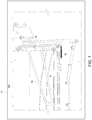
- FIG. 1 is a partial schematic view of a device 10 according to an example.
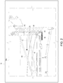
- FIG. 2 is a partial schematic view of device 10 of FIG. 1 according to an example.
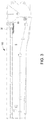
- FIG. 3 is a partial side schematic view of device 10 of FIG. 1 depicting an output tray assembly 100 according to an example.
- device 10 includes an output tray 15, an axle 20, a force providing member 30, a bail arm 40, a pin 50, and an arm 60.
- bail arm 40 is coupled to device 10 above output tray 15 to provide a downward force on output tray 15.
- force providing member 30 is coupled to bail arm 40 to provide a counter force to the downward force applied by bail arm 40 on output tray 15.
- device 10 may be any device to output media which may be stacked on an output tray, such as an imaging device, a finisher, etc
- An "imaging device” may be a hardware device, such as a printer, multifunction printer (MFP), or any other device with functionalities to physically produce graphical representation(s) (e.g., text, images, models etc.) on paper, photopolymers, thermopolymers, plastics, fabric, composite, metal, wood, or the like.
- MFP multifunction printer
- an MFP may be capable of performing a combination of multiple different functionalities such as, for example, printing, photocopying, scanning, faxing, etc.
- media may be any type of paper, photopolymers, thermopolymers, plastics, fabric, composite, metal, wood, etc., which may be stacked in an output tray 15 of device 10.
- device 10 may output media along media path 17.
- media path 17 may be an output media path or a media ejection path for media ejected by device 10.
- device 10 may be an inkjet printer to eject paper along media path 17 onto output tray 15.
- device 10 may a laser printer to output media onto output tray 15.
- output tray 15 may be any structure to receive media output from device 10. In some examples, output tray 15 may be integrated into device 10. In other examples, output tray 15 may be a separate device coupled to device 10. In examples, output tray 15 may include a surface to receive multiple sheets or a stack of output media from device 10. Various parameters related to output tray 15 may be selected for the particular use and design of device 10. For example, the dimensions and orientation of output tray 15 may be determined by the size of the device 10 and the particular use of the system.
- axle 20 may be coupled to device 10 above the receiving surface of output tray 15, Axle 20 includes a central axis 25.
- Axle 20 may be any type of shaft about which an object may rotate.
- axle 20 may be composed of any material to allow axle 20 to securely couple to and retain bail arm 40 on device 10 such as metal, plastic, composite, wood, etc.
- force providing member 30 may be any type of force providing member to apply a force.
- force providing member 30 may provide a force opposite to a rotational force of bail arm 40 about central axis 25.
- force providing member 30 may be a spring, such as a coiled torsion spring. According to the invention the force applied by force providing member 30 is transferred to bail arm 40 via axle 20.
- bail arm 40 may be any component with a surface area to apply a downward force on output tray 15.
- bail arm 40 may be configured to engage or contact a medium as it travels along media path 17 onto output tray 15.
- bail arm 40 may be configured to apply a downward force to a medium in output tray 15.
- bail arm 40 may apply sufficient force to medium traveling along media path 17 to retain the medium in output tray 15.
- bail arm 40 may be configured to apply sufficient force to retain paper being ejected by an inkjet printer into an output tray that includes a number of printed pages stacked thereon.
- bail arm 40 may be composed of any material with sufficient structural integrity to apply the downward force on output tray 15.
- bail arm 40 may be composed of a metal, such as aluminum, a metal composite, such as steel, a plastic, a wood, a composite, such as carbon fiber, carbon reinforced plastics, glass-filled plastic, glass-filled nylon, glass-filled polycarbonate, glass filled acrylonitrile butadiene styrene (ABS), etc.
- Various parameters related to bail arm 40 may be selected for the particular use and design of device 10.
- the dimensions and orientation of bail arm 40 may be determined by the size of the device 10, the size and orientation of media stacked on output tray 15, the ejection rate of media onto output tray 15, and the particular use of the system.
- the dimensions of bail arm 40 may be chosen to allow variability in the dimensions of output media.
- bail arm 40 may be dimensioned to contact different sized media, such as, A3 media or A4 media.
- bail arm 40 may be coupled to axle 20 in any manner to rotate about central axis 25.
- bail arm 40 may freely rotate about central axis 25 until it comes in contact with another component, for example, output tray 15 disposed below axle 20.
- a bail arm 40 may rotate about central axis 25 in response to the force of gravity on bail arm 40.
- force providing member 30 may provide a counter force to the force of gravity on the bail arm to reduce the force bail arm 40 applies to output tray 15. According to the invention, the counter force supplied by force providing member 30 is transferred to bail arm 40 via axle 20.
- axle 20 may be coupled to force providing member 30 via an arm 60.
- force providing member 30 may be disposed along a sidewall 5 of output tray assembly 100.
- arm 60 may be dimensioned to couple force providing member 30 and axle 20.
- one or more intermediate components may be disposed to couple force providing member 30 and axle 20.
- a pin 50 may connect axle 20 to bail arm 40. In such examples, pin 50 may transfer the counter force from force providing member 30 to the bail arm 40.
- FIG. 4 is a partial schematic rear view of output tray assembly 400 according to an example that is not within the scope of the claims.
- a force providing member 430 may be disposed to engage axle 20.
- force providing member 430 may be coupled to bail arm 40 at a first end to provide a counter force to the force of gravity on bail arm 40.
- force providing member 30 may be connected to pin 50 at a first end to provide a counter force to the force of gravity on bail arm 40.
- force providing member 430 may be connected to bail arm 40 directly at the first end.
- a second end of force providing member 30 may be connected to a frame (not shown) of output tray assembly 400.
- bail arm 40 may rotate about axle 20 such that bail arm 40 provides a downward force to a media stack ejected onto output tray 15.
- Force providing member 30 provides a counter force to the force of gravity on bail arm 40 to reduce the weight of bail arm 40 on the media stack.
- bail arm 40 may be able to control different sized media being ejected onto output tray 15 at the same time.
- the dimensions of bail arm 40 may be optimized to control different sized media while maintaining the same effective weight of bail arm 40 on output tray 15 by use of force providing member 30.
Landscapes
- Engineering & Computer Science (AREA)
- Mechanical Engineering (AREA)
- Pile Receivers (AREA)
- Handling Of Sheets (AREA)
Claims (11)
- Vorrichtung (10), die Folgendes umfasst:einen Haltearm (40), um Ausgabemedien zu steuern, wobei der Haltearm (40) konfiguriert ist, eine Kraft auf ein Ausgabefach auszuüben; undein Kraftbereitstellungselement (30), das mit dem Haltearm gekoppelt ist, um eine Gegenkraft bereitzustellen, um die durch den Haltearm auf das Ausgabefach ausgeübte Kraft zu reduzieren, dadurch gekennzeichnet, dass die Vorrichtung eine Achse (20) umfasst, die mit dem Haltearm (40) gekoppelt ist, um die sich der Haltearm drehen kann, um die Gegenkraft von dem Kraftbereitstellungselement (30) auf den Haltearm zu übertragen.
- Vorrichtung (10) nach Anspruch 1, die ferner einen Stift (50) umfasst, um die Achse (20) mit dem Haltearm (40) zu koppeln und um die Gegenkraft auf den Haltearm zu übertragen.
- Vorrichtung (10) nach Anspruch 1, die ferner einen Arm (60) umfasst, der mit dem Kraftbereitstellungselement (30) gekoppelt ist.
- Vorrichtung (10) nach Anspruch 1, wobei die durch das Kraftbereitstellungselement (30) ausgeübte Gegenkraft geringer als eine auf den Haltearm (40) ausgeübte Schwerkraft ist.
- Vorrichtung (10) nach Anspruch 1, wobei der Haltearm (40) aus einem kohlenstoffverstärkten Kunststoff, einem mit Glas gefüllten Kunststoff, einem mit Glas gefüllten Nylon, einem mit Glas gefüllten Polycarbonat, einem mit Glas gefüllten Acrylnitrilbutadienstyrol (ABS), einem Metall, einem Metallverbundstoff, einem Kunststoff und/oder einem Holz besteht.
- Vorrichtung (10) nach Anspruch 1, wobei das Kraftbereitstellungselement (30) eine gewundene Torsionsfeder ist.
- Ausgabefachanordnung (100, 400), die Folgendes umfasst:
die Vorrichtung (10) nach Anspruch 1, wobei das Kraftbereitstellungselement (30) eine Feder umfasst, die mit der Achse (20) gekoppelt ist. - Ausgabefachanordnung (100, 400) nach Anspruch 7, die ferner Folgendes umfasst: (i) einen Stift (50), um die Gegenkraft von der Feder auf den Haltearm (40) zu übertragen; und/oder (ii) einen Arm (60), der mit der Feder und der Achse (20) gekoppelt ist.
- Ausgabefachanordnung (100, 400) nach Anspruch 8, wobei die Feder mit einem Rahmen der Ausgabefachanordnung verbunden ist.
- Bildgebungsvorrichtung, die Folgendes umfasst:die Vorrichtung (10) nach Anspruch 4,
wobei das Kraftbereitstellungselement (30) eine gewundene Torsionsfeder umfasst, die mit der Achse (20) gekoppelt ist; undeinen Stift (50), um die Gegenkraft von der Feder auf den Haltearm (40) zu übertragen. - Bilderzeugungsvorrichtung nach Anspruch 10, die ferner einen Arm (60) umfasst, der mit der Feder und der Achse (20) gekoppelt ist.
Applications Claiming Priority (1)
| Application Number | Priority Date | Filing Date | Title |
|---|---|---|---|
| PCT/US2016/030018 WO2017188974A1 (en) | 2016-04-29 | 2016-04-29 | Bail arm to apply force |
Publications (3)
| Publication Number | Publication Date |
|---|---|
| EP3448686A1 EP3448686A1 (de) | 2019-03-06 |
| EP3448686A4 EP3448686A4 (de) | 2020-01-01 |
| EP3448686B1 true EP3448686B1 (de) | 2021-11-24 |
Family
ID=60159941
Family Applications (1)
| Application Number | Title | Priority Date | Filing Date |
|---|---|---|---|
| EP16900711.9A Not-in-force EP3448686B1 (de) | 2016-04-29 | 2016-04-29 | Vorrichtung umfassend einen bügelarm zum anwenden einer kraft, und entsprechende auffangbehältereinrichtung sowie bilderzeugungsvorrichtung |
Country Status (4)
| Country | Link |
|---|---|
| US (1) | US20190023036A1 (de) |
| EP (1) | EP3448686B1 (de) |
| CN (1) | CN109070607B (de) |
| WO (1) | WO2017188974A1 (de) |
Family Cites Families (23)
| Publication number | Priority date | Publication date | Assignee | Title |
|---|---|---|---|---|
| FR2387788A1 (fr) * | 1977-04-20 | 1978-11-17 | Sato Kenkyusho | Mecanisme d'impression a pression constante pour etiqueteuse a main |
| JPS58197148A (ja) * | 1982-05-12 | 1983-11-16 | Hitachi Koki Co Ltd | カットシ−トスタック装置 |
| JPS648178A (en) * | 1987-06-29 | 1989-01-12 | Toshiba Corp | Image forming device |
| US5260759A (en) * | 1990-07-31 | 1993-11-09 | Canon Kabushiki Kaisha | Image forming system having sheet hold-down device |
| JP2983077B2 (ja) * | 1991-02-06 | 1999-11-29 | 株式会社リコー | 用紙排出装置 |
| US5120047A (en) * | 1991-02-07 | 1992-06-09 | Xerox Corporation | Integral sheet stacking buckle suppressor and registration edge |
| JPH04277158A (ja) * | 1991-03-01 | 1992-10-02 | Canon Inc | 画像形成装置の排紙トレイ装置 |
| JPH06127791A (ja) * | 1992-09-25 | 1994-05-10 | Fuji Xerox Co Ltd | 排出用紙収納トレイ |
| JPH0940264A (ja) * | 1995-07-21 | 1997-02-10 | Shinko Seisakusho Co Ltd | シート状体の収納装置 |
| JP3581449B2 (ja) * | 1995-08-31 | 2004-10-27 | 株式会社 沖情報システムズ | 媒体処理装置 |
| JP3621565B2 (ja) * | 1997-08-27 | 2005-02-16 | 株式会社リコー | シート整合装置および画像形成装置 |
| KR100565094B1 (ko) * | 2004-11-24 | 2006-03-30 | 삼성전자주식회사 | 용지검출장치 및 이를 구비한 화상형성장치 |
| JP4920939B2 (ja) * | 2005-09-28 | 2012-04-18 | キヤノン株式会社 | シート排出装置及び画像形成装置 |
| JP2008044771A (ja) * | 2006-08-21 | 2008-02-28 | Kyocera Mita Corp | 画像形成装置 |
| JP5040494B2 (ja) * | 2007-07-18 | 2012-10-03 | セイコーエプソン株式会社 | シート収納装置および媒体処理装置 |
| JP2009067594A (ja) * | 2007-09-11 | 2009-04-02 | Toshiba Corp | 用紙積載装置および用紙積載方法 |
| JP2009091094A (ja) * | 2007-10-05 | 2009-04-30 | Brother Ind Ltd | 画像形成装置 |
| JP5390164B2 (ja) * | 2008-10-17 | 2014-01-15 | 富士通フロンテック株式会社 | 紙葉類排出集積装置 |
| JP5301975B2 (ja) * | 2008-12-11 | 2013-09-25 | ニスカ株式会社 | シート集積方法、シート集積装置および後処理装置並びに画像形成システム |
| JP5401179B2 (ja) * | 2009-06-17 | 2014-01-29 | 株式会社沖データ | 画像形成装置 |
| JP5421032B2 (ja) * | 2009-08-31 | 2014-02-19 | ニスカ株式会社 | シート集積装置及びこれを備えた画像形成システム |
| JP5701260B2 (ja) * | 2012-07-24 | 2015-04-15 | 京セラドキュメントソリューションズ株式会社 | シート排出装置、及び画像形成装置 |
| JP6245004B2 (ja) * | 2014-03-13 | 2017-12-13 | コニカミノルタ株式会社 | 排紙装置及び画像形成装置 |
-
2016
- 2016-04-29 CN CN201680084522.1A patent/CN109070607B/zh not_active Expired - Fee Related
- 2016-04-29 WO PCT/US2016/030018 patent/WO2017188974A1/en not_active Ceased
- 2016-04-29 US US16/067,299 patent/US20190023036A1/en not_active Abandoned
- 2016-04-29 EP EP16900711.9A patent/EP3448686B1/de not_active Not-in-force
Also Published As
| Publication number | Publication date |
|---|---|
| EP3448686A1 (de) | 2019-03-06 |
| CN109070607B (zh) | 2021-01-22 |
| US20190023036A1 (en) | 2019-01-24 |
| EP3448686A4 (de) | 2020-01-01 |
| CN109070607A (zh) | 2018-12-21 |
| WO2017188974A1 (en) | 2017-11-02 |
Similar Documents
| Publication | Publication Date | Title |
|---|---|---|
| US7237969B2 (en) | Dual output tray | |
| US6582039B2 (en) | Combination color inkjet and laser image-printing device with dual paper-picking mechanism and method of implementing same | |
| US8608308B2 (en) | Image recording device | |
| US7980554B2 (en) | Friction backup roller for media picking | |
| EP3442891B1 (de) | Bügelarm zum drehen und schwingen, und entsprechende auffangbehältereinrichtung | |
| JPH11217132A (ja) | 自動給紙装置 | |
| US20190144221A1 (en) | Bail arm | |
| EP3448686B1 (de) | Vorrichtung umfassend einen bügelarm zum anwenden einer kraft, und entsprechende auffangbehältereinrichtung sowie bilderzeugungsvorrichtung | |
| US6597889B2 (en) | Dual paper picking mechanism and method for increasing speed and reliability of paper path delivery | |
| US20210187978A1 (en) | Flap to direct medium | |
| US8200117B2 (en) | Image forming apparatus having pivotable upper body | |
| US8100489B2 (en) | Double-sided printing system | |
| JP2011090266A (ja) | 複合画像形成装置 | |
| US20060197820A1 (en) | Print media stacking unit and image forming apparatus with the same | |
| EP2028569B1 (de) | Bilderzeugungsvorrichtung | |
| US11332337B2 (en) | Flexible bails on printers | |
| JP2004083216A (ja) | 記録媒体搬送装置およびそれを備えた記録装置 | |
| JP2021104887A (ja) | 給紙装置およびそれを備える画像形成装置 | |
| JPH06189062A (ja) | 画像形成装置、及び排紙装置 | |
| JP2002255384A (ja) | シート材の送り装置 | |
| JP2005029346A (ja) | 給紙装置および記録装置 | |
| JP2007131421A (ja) | 媒体供給機構及び液体噴射装置と記録装置 |
Legal Events
| Date | Code | Title | Description |
|---|---|---|---|
| STAA | Information on the status of an ep patent application or granted ep patent |
Free format text: STATUS: THE INTERNATIONAL PUBLICATION HAS BEEN MADE |
|
| PUAI | Public reference made under article 153(3) epc to a published international application that has entered the european phase |
Free format text: ORIGINAL CODE: 0009012 |
|
| STAA | Information on the status of an ep patent application or granted ep patent |
Free format text: STATUS: REQUEST FOR EXAMINATION WAS MADE |
|
| 17P | Request for examination filed |
Effective date: 20180724 |
|
| AK | Designated contracting states |
Kind code of ref document: A1 Designated state(s): AL AT BE BG CH CY CZ DE DK EE ES FI FR GB GR HR HU IE IS IT LI LT LU LV MC MK MT NL NO PL PT RO RS SE SI SK SM TR |
|
| AX | Request for extension of the european patent |
Extension state: BA ME |
|
| RAP1 | Party data changed (applicant data changed or rights of an application transferred) |
Owner name: HEWLETT-PACKARD DEVELOPMENT COMPANY, L.P. |
|
| DAV | Request for validation of the european patent (deleted) | ||
| DAX | Request for extension of the european patent (deleted) | ||
| REG | Reference to a national code |
Ref country code: DE Ref legal event code: R079 Ref document number: 602016066690 Country of ref document: DE Free format text: PREVIOUS MAIN CLASS: B41J0013000000 Ipc: B65H0031260000 |
|
| A4 | Supplementary search report drawn up and despatched |
Effective date: 20191203 |
|
| RIC1 | Information provided on ipc code assigned before grant |
Ipc: B65H 31/02 20060101ALI20191127BHEP Ipc: B65H 31/26 20060101AFI20191127BHEP |
|
| STAA | Information on the status of an ep patent application or granted ep patent |
Free format text: STATUS: EXAMINATION IS IN PROGRESS |
|
| 17Q | First examination report despatched |
Effective date: 20201208 |
|
| GRAP | Despatch of communication of intention to grant a patent |
Free format text: ORIGINAL CODE: EPIDOSNIGR1 |
|
| STAA | Information on the status of an ep patent application or granted ep patent |
Free format text: STATUS: GRANT OF PATENT IS INTENDED |
|
| INTG | Intention to grant announced |
Effective date: 20210721 |
|
| GRAS | Grant fee paid |
Free format text: ORIGINAL CODE: EPIDOSNIGR3 |
|
| GRAA | (expected) grant |
Free format text: ORIGINAL CODE: 0009210 |
|
| STAA | Information on the status of an ep patent application or granted ep patent |
Free format text: STATUS: THE PATENT HAS BEEN GRANTED |
|
| AK | Designated contracting states |
Kind code of ref document: B1 Designated state(s): AL AT BE BG CH CY CZ DE DK EE ES FI FR GB GR HR HU IE IS IT LI LT LU LV MC MK MT NL NO PL PT RO RS SE SI SK SM TR |
|
| REG | Reference to a national code |
Ref country code: GB Ref legal event code: FG4D |
|
| REG | Reference to a national code |
Ref country code: AT Ref legal event code: REF Ref document number: 1449720 Country of ref document: AT Kind code of ref document: T Effective date: 20211215 |
|
| REG | Reference to a national code |
Ref country code: DE Ref legal event code: R096 Ref document number: 602016066690 Country of ref document: DE |
|
| REG | Reference to a national code |
Ref country code: IE Ref legal event code: FG4D |
|
| REG | Reference to a national code |
Ref country code: LT Ref legal event code: MG9D |
|
| REG | Reference to a national code |
Ref country code: NL Ref legal event code: MP Effective date: 20211124 |
|
| REG | Reference to a national code |
Ref country code: AT Ref legal event code: MK05 Ref document number: 1449720 Country of ref document: AT Kind code of ref document: T Effective date: 20211124 |
|
| PG25 | Lapsed in a contracting state [announced via postgrant information from national office to epo] |
Ref country code: RS Free format text: LAPSE BECAUSE OF FAILURE TO SUBMIT A TRANSLATION OF THE DESCRIPTION OR TO PAY THE FEE WITHIN THE PRESCRIBED TIME-LIMIT Effective date: 20211124 Ref country code: LT Free format text: LAPSE BECAUSE OF FAILURE TO SUBMIT A TRANSLATION OF THE DESCRIPTION OR TO PAY THE FEE WITHIN THE PRESCRIBED TIME-LIMIT Effective date: 20211124 Ref country code: FI Free format text: LAPSE BECAUSE OF FAILURE TO SUBMIT A TRANSLATION OF THE DESCRIPTION OR TO PAY THE FEE WITHIN THE PRESCRIBED TIME-LIMIT Effective date: 20211124 Ref country code: BG Free format text: LAPSE BECAUSE OF FAILURE TO SUBMIT A TRANSLATION OF THE DESCRIPTION OR TO PAY THE FEE WITHIN THE PRESCRIBED TIME-LIMIT Effective date: 20220224 Ref country code: AT Free format text: LAPSE BECAUSE OF FAILURE TO SUBMIT A TRANSLATION OF THE DESCRIPTION OR TO PAY THE FEE WITHIN THE PRESCRIBED TIME-LIMIT Effective date: 20211124 |
|
| PG25 | Lapsed in a contracting state [announced via postgrant information from national office to epo] |
Ref country code: IS Free format text: LAPSE BECAUSE OF FAILURE TO SUBMIT A TRANSLATION OF THE DESCRIPTION OR TO PAY THE FEE WITHIN THE PRESCRIBED TIME-LIMIT Effective date: 20220324 Ref country code: SE Free format text: LAPSE BECAUSE OF FAILURE TO SUBMIT A TRANSLATION OF THE DESCRIPTION OR TO PAY THE FEE WITHIN THE PRESCRIBED TIME-LIMIT Effective date: 20211124 Ref country code: PT Free format text: LAPSE BECAUSE OF FAILURE TO SUBMIT A TRANSLATION OF THE DESCRIPTION OR TO PAY THE FEE WITHIN THE PRESCRIBED TIME-LIMIT Effective date: 20220324 Ref country code: PL Free format text: LAPSE BECAUSE OF FAILURE TO SUBMIT A TRANSLATION OF THE DESCRIPTION OR TO PAY THE FEE WITHIN THE PRESCRIBED TIME-LIMIT Effective date: 20211124 Ref country code: NO Free format text: LAPSE BECAUSE OF FAILURE TO SUBMIT A TRANSLATION OF THE DESCRIPTION OR TO PAY THE FEE WITHIN THE PRESCRIBED TIME-LIMIT Effective date: 20220224 Ref country code: NL Free format text: LAPSE BECAUSE OF FAILURE TO SUBMIT A TRANSLATION OF THE DESCRIPTION OR TO PAY THE FEE WITHIN THE PRESCRIBED TIME-LIMIT Effective date: 20211124 Ref country code: LV Free format text: LAPSE BECAUSE OF FAILURE TO SUBMIT A TRANSLATION OF THE DESCRIPTION OR TO PAY THE FEE WITHIN THE PRESCRIBED TIME-LIMIT Effective date: 20211124 Ref country code: HR Free format text: LAPSE BECAUSE OF FAILURE TO SUBMIT A TRANSLATION OF THE DESCRIPTION OR TO PAY THE FEE WITHIN THE PRESCRIBED TIME-LIMIT Effective date: 20211124 Ref country code: GR Free format text: LAPSE BECAUSE OF FAILURE TO SUBMIT A TRANSLATION OF THE DESCRIPTION OR TO PAY THE FEE WITHIN THE PRESCRIBED TIME-LIMIT Effective date: 20220225 Ref country code: ES Free format text: LAPSE BECAUSE OF FAILURE TO SUBMIT A TRANSLATION OF THE DESCRIPTION OR TO PAY THE FEE WITHIN THE PRESCRIBED TIME-LIMIT Effective date: 20211124 |
|
| PG25 | Lapsed in a contracting state [announced via postgrant information from national office to epo] |
Ref country code: SM Free format text: LAPSE BECAUSE OF FAILURE TO SUBMIT A TRANSLATION OF THE DESCRIPTION OR TO PAY THE FEE WITHIN THE PRESCRIBED TIME-LIMIT Effective date: 20211124 Ref country code: SK Free format text: LAPSE BECAUSE OF FAILURE TO SUBMIT A TRANSLATION OF THE DESCRIPTION OR TO PAY THE FEE WITHIN THE PRESCRIBED TIME-LIMIT Effective date: 20211124 Ref country code: RO Free format text: LAPSE BECAUSE OF FAILURE TO SUBMIT A TRANSLATION OF THE DESCRIPTION OR TO PAY THE FEE WITHIN THE PRESCRIBED TIME-LIMIT Effective date: 20211124 Ref country code: EE Free format text: LAPSE BECAUSE OF FAILURE TO SUBMIT A TRANSLATION OF THE DESCRIPTION OR TO PAY THE FEE WITHIN THE PRESCRIBED TIME-LIMIT Effective date: 20211124 Ref country code: DK Free format text: LAPSE BECAUSE OF FAILURE TO SUBMIT A TRANSLATION OF THE DESCRIPTION OR TO PAY THE FEE WITHIN THE PRESCRIBED TIME-LIMIT Effective date: 20211124 Ref country code: CZ Free format text: LAPSE BECAUSE OF FAILURE TO SUBMIT A TRANSLATION OF THE DESCRIPTION OR TO PAY THE FEE WITHIN THE PRESCRIBED TIME-LIMIT Effective date: 20211124 |
|
| REG | Reference to a national code |
Ref country code: DE Ref legal event code: R097 Ref document number: 602016066690 Country of ref document: DE |
|
| PLBE | No opposition filed within time limit |
Free format text: ORIGINAL CODE: 0009261 |
|
| STAA | Information on the status of an ep patent application or granted ep patent |
Free format text: STATUS: NO OPPOSITION FILED WITHIN TIME LIMIT |
|
| PG25 | Lapsed in a contracting state [announced via postgrant information from national office to epo] |
Ref country code: AL Free format text: LAPSE BECAUSE OF FAILURE TO SUBMIT A TRANSLATION OF THE DESCRIPTION OR TO PAY THE FEE WITHIN THE PRESCRIBED TIME-LIMIT Effective date: 20211124 |
|
| 26N | No opposition filed |
Effective date: 20220825 |
|
| REG | Reference to a national code |
Ref country code: DE Ref legal event code: R119 Ref document number: 602016066690 Country of ref document: DE |
|
| PG25 | Lapsed in a contracting state [announced via postgrant information from national office to epo] |
Ref country code: SI Free format text: LAPSE BECAUSE OF FAILURE TO SUBMIT A TRANSLATION OF THE DESCRIPTION OR TO PAY THE FEE WITHIN THE PRESCRIBED TIME-LIMIT Effective date: 20211124 |
|
| REG | Reference to a national code |
Ref country code: CH Ref legal event code: PL |
|
| GBPC | Gb: european patent ceased through non-payment of renewal fee |
Effective date: 20220429 |
|
| REG | Reference to a national code |
Ref country code: BE Ref legal event code: MM Effective date: 20220430 |
|
| PG25 | Lapsed in a contracting state [announced via postgrant information from national office to epo] |
Ref country code: MC Free format text: LAPSE BECAUSE OF FAILURE TO SUBMIT A TRANSLATION OF THE DESCRIPTION OR TO PAY THE FEE WITHIN THE PRESCRIBED TIME-LIMIT Effective date: 20211124 Ref country code: LU Free format text: LAPSE BECAUSE OF NON-PAYMENT OF DUE FEES Effective date: 20220429 Ref country code: LI Free format text: LAPSE BECAUSE OF NON-PAYMENT OF DUE FEES Effective date: 20220430 Ref country code: GB Free format text: LAPSE BECAUSE OF NON-PAYMENT OF DUE FEES Effective date: 20220429 Ref country code: FR Free format text: LAPSE BECAUSE OF NON-PAYMENT OF DUE FEES Effective date: 20220430 Ref country code: DE Free format text: LAPSE BECAUSE OF NON-PAYMENT OF DUE FEES Effective date: 20221103 Ref country code: CH Free format text: LAPSE BECAUSE OF NON-PAYMENT OF DUE FEES Effective date: 20220430 |
|
| PG25 | Lapsed in a contracting state [announced via postgrant information from national office to epo] |
Ref country code: BE Free format text: LAPSE BECAUSE OF NON-PAYMENT OF DUE FEES Effective date: 20220430 |
|
| PG25 | Lapsed in a contracting state [announced via postgrant information from national office to epo] |
Ref country code: IE Free format text: LAPSE BECAUSE OF NON-PAYMENT OF DUE FEES Effective date: 20220429 |
|
| PG25 | Lapsed in a contracting state [announced via postgrant information from national office to epo] |
Ref country code: IT Free format text: LAPSE BECAUSE OF FAILURE TO SUBMIT A TRANSLATION OF THE DESCRIPTION OR TO PAY THE FEE WITHIN THE PRESCRIBED TIME-LIMIT Effective date: 20211124 |
|
| PG25 | Lapsed in a contracting state [announced via postgrant information from national office to epo] |
Ref country code: HU Free format text: LAPSE BECAUSE OF FAILURE TO SUBMIT A TRANSLATION OF THE DESCRIPTION OR TO PAY THE FEE WITHIN THE PRESCRIBED TIME-LIMIT; INVALID AB INITIO Effective date: 20160429 |
|
| PG25 | Lapsed in a contracting state [announced via postgrant information from national office to epo] |
Ref country code: MK Free format text: LAPSE BECAUSE OF FAILURE TO SUBMIT A TRANSLATION OF THE DESCRIPTION OR TO PAY THE FEE WITHIN THE PRESCRIBED TIME-LIMIT Effective date: 20211124 Ref country code: CY Free format text: LAPSE BECAUSE OF FAILURE TO SUBMIT A TRANSLATION OF THE DESCRIPTION OR TO PAY THE FEE WITHIN THE PRESCRIBED TIME-LIMIT Effective date: 20211124 |
|
| PG25 | Lapsed in a contracting state [announced via postgrant information from national office to epo] |
Ref country code: TR Free format text: LAPSE BECAUSE OF FAILURE TO SUBMIT A TRANSLATION OF THE DESCRIPTION OR TO PAY THE FEE WITHIN THE PRESCRIBED TIME-LIMIT Effective date: 20211124 |
|
| PG25 | Lapsed in a contracting state [announced via postgrant information from national office to epo] |
Ref country code: MT Free format text: LAPSE BECAUSE OF FAILURE TO SUBMIT A TRANSLATION OF THE DESCRIPTION OR TO PAY THE FEE WITHIN THE PRESCRIBED TIME-LIMIT Effective date: 20211124 |