EP3448121B1 - Mikrowelleneinspeisevorrichtung an einem mikrowellenherd - Google Patents
Mikrowelleneinspeisevorrichtung an einem mikrowellenherd Download PDFInfo
- Publication number
- EP3448121B1 EP3448121B1 EP17187390.4A EP17187390A EP3448121B1 EP 3448121 B1 EP3448121 B1 EP 3448121B1 EP 17187390 A EP17187390 A EP 17187390A EP 3448121 B1 EP3448121 B1 EP 3448121B1
- Authority
- EP
- European Patent Office
- Prior art keywords
- coupling
- power
- coupling element
- branch
- waveguide
- Prior art date
- Legal status (The legal status is an assumption and is not a legal conclusion. Google has not performed a legal analysis and makes no representation as to the accuracy of the status listed.)
- Active
Links
- 238000010168 coupling process Methods 0.000 claims description 61
- 238000005859 coupling reaction Methods 0.000 claims description 61
- 230000008878 coupling Effects 0.000 claims description 60
- 238000010411 cooking Methods 0.000 claims description 37
- 230000005540 biological transmission Effects 0.000 claims description 11
- 238000000034 method Methods 0.000 claims description 3
- 230000005672 electromagnetic field Effects 0.000 description 5
- 238000010438 heat treatment Methods 0.000 description 2
- 239000007787 solid Substances 0.000 description 2
- 230000015572 biosynthetic process Effects 0.000 description 1
- 230000001066 destructive effect Effects 0.000 description 1
- 230000005670 electromagnetic radiation Effects 0.000 description 1
- 238000005516 engineering process Methods 0.000 description 1
- 230000002452 interceptive effect Effects 0.000 description 1
- 239000002184 metal Substances 0.000 description 1
- 230000001902 propagating effect Effects 0.000 description 1
- 230000005855 radiation Effects 0.000 description 1
Images

Classifications
-
- H—ELECTRICITY
- H05—ELECTRIC TECHNIQUES NOT OTHERWISE PROVIDED FOR
- H05B—ELECTRIC HEATING; ELECTRIC LIGHT SOURCES NOT OTHERWISE PROVIDED FOR; CIRCUIT ARRANGEMENTS FOR ELECTRIC LIGHT SOURCES, IN GENERAL
- H05B6/00—Heating by electric, magnetic or electromagnetic fields
- H05B6/64—Heating using microwaves
- H05B6/66—Circuits
- H05B6/68—Circuits for monitoring or control
-
- H—ELECTRICITY
- H05—ELECTRIC TECHNIQUES NOT OTHERWISE PROVIDED FOR
- H05B—ELECTRIC HEATING; ELECTRIC LIGHT SOURCES NOT OTHERWISE PROVIDED FOR; CIRCUIT ARRANGEMENTS FOR ELECTRIC LIGHT SOURCES, IN GENERAL
- H05B6/00—Heating by electric, magnetic or electromagnetic fields
- H05B6/64—Heating using microwaves
- H05B6/70—Feed lines
- H05B6/707—Feed lines using waveguides
-
- F—MECHANICAL ENGINEERING; LIGHTING; HEATING; WEAPONS; BLASTING
- F24—HEATING; RANGES; VENTILATING
- F24C—DOMESTIC STOVES OR RANGES ; DETAILS OF DOMESTIC STOVES OR RANGES, OF GENERAL APPLICATION
- F24C7/00—Stoves or ranges heated by electric energy
- F24C7/06—Arrangement or mounting of electric heating elements
- F24C7/067—Arrangement or mounting of electric heating elements on ranges
-
- H—ELECTRICITY
- H05—ELECTRIC TECHNIQUES NOT OTHERWISE PROVIDED FOR
- H05B—ELECTRIC HEATING; ELECTRIC LIGHT SOURCES NOT OTHERWISE PROVIDED FOR; CIRCUIT ARRANGEMENTS FOR ELECTRIC LIGHT SOURCES, IN GENERAL
- H05B6/00—Heating by electric, magnetic or electromagnetic fields
- H05B6/64—Heating using microwaves
- H05B6/70—Feed lines
- H05B6/705—Feed lines using microwave tuning
Definitions
- the invention relates to a device for feeding an electromagnetic alternating field generated by a microwave transmitter into a cooking chamber of a microwave oven, the electromagnetic alternating field being transmitted in one power flow direction by means of a transmission device from the microwave transmitter to a plurality of feed points in the cooking chamber, at which the electromagnetic power generated by the microwave transmitter enters the Cooking chamber is fed, the transmission device having at least one waveguide and a coupling element coupled to the waveguide, the coupling element designed as a power distributor connecting the microwave transmitter to a plurality of waveguides.
- the invention also relates to a method for operating such a device.
- microwave ovens Devices for feeding alternating electromagnetic fields into a cooking space are known as "microwave ovens".
- the electromagnetic alternating field is generated by a microwave transmitter which has a magnetron for this purpose.
- the microwaves are transmitted to a coupling element via a coupling-out section.
- the coupling element couples the electromagnetic alternating field to a waveguide which opens into the cooking space.
- the coupling element and the decoupling section can form an impedance converter.
- the electromagnetic waves spread out in the direction of their emission at the feed points and are released several times from the walls reflected. There is no homogeneous field distribution within the cooking space, so that the heating of food within the cooking space is not homogeneous. Standing waves that arise in the cooking space are destructively or constructively superimposed. There remain hot or cold spots.
- the EP 0 284 958 A1 proposes a device for coupling a microwave field to a microwave oven, in which coupling pins are provided within a resonator chamber which are intended to cause a rotation of the electromagnetic field coupled into the resonator chamber so that unpolarized alternating field can emerge from a feed opening. It is also proposed there to connect two transmitters, each with a waveguide, to a common resonator chamber, which in turn is coupled to the cooking chamber via several coupling openings.
- Microwave ovens are known in which an electromagnetic alternating field is transmitted by means of a transmission device from a microwave transmitter to several feed points of the cooking chamber, the transmission device having a waveguide and a coupling element coupled to it, which coupling element in turn connects the microwave transmitter with several waveguides.
- the invention is based on the object of proposing measures with which the food to be heated is heated more evenly and thus has a more homogeneous temperature distribution.
- the transmission device with which the electromagnetic alternating field and thus the power generated by the microwave transmitter is transmitted from the microwave transmitter to the feed points has a coupling element and several waveguides, the coupling element being a coupling pin having several arms.
- the electromagnetic alternating field is fed into the coupling element and, with its help, divided over several waveguides, so that it can be conducted into the cooking chamber in several different ways, since each waveguide opens into the cooking chamber at an individually assigned feed point.
- the electromagnetic alternating field is, for example, also generated in a magnetron and fed into a coupling branch of the coupling element, for example.
- the coupling element can have several decoupling branches which divide the power fed into the coupling element to the several waveguides. This can take place in accordance with a predetermined power sharing ratio.
- the power coupled into the coupling branch is preferably transmitted uniformly to all coupling branches.
- the coupling element can be formed from an electrically conductive body, in particular from a metal body.
- One arm of the coupling element acts as a coupling branch.
- Several other arms of the coupling element act as decoupling branches.
- the coupling element forms a switch with which electromagnetic waves generated by a single source are distributed to several outputs can.
- a feed point is preferably assigned to each output.
- the feed points are preferably arranged on at least two walls of the cooking chamber that are at an angle to one another.
- the device according to the invention can reduce the formation of cold and hot zones within the food to be cooked.
- the coupling element is designed as a multi-way switch.
- the individual decoupling branches can also be brought from a power-transmitting functional position into a non-power-transmitting functional position with respect to the coupling-in branch.
- This makes it possible to feed the power into the cooking chamber through different feed points in a chronological sequence, whereby it is also provided in particular that the alternating electromagnetic fields are fed into the cooking chamber one after the other through different groups of feed points.
- the feed points can be realized through openings, at each of which a waveguide opens into the cooking space. As a result, individual zones or radiation paths within the cooking space can be supplied with microwave energy one after the other in a time-controlled manner.
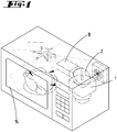
- the Figure 1 shows a microwave oven according to the prior art, in which a wall-bounded cooking space 14 is provided within a housing, into which a waveguide 8 opens at a feed point, into which power is coupled in the form of an electromagnetic alternating field.
- the electromagnetic alternating field is generated in a magnetron 1 and is coupled into the waveguide 8 via a decoupling section 2.
- a multiple reflection of the propagating electromagnetic alternating field takes place within the cooking chamber 14.
- the energy transported with the electromagnetic alternating field is converted into heat within the food.
- a paddle wheel is arranged on the ceiling of the cooking chamber 14 to homogenize the field distribution.
- the Figure 2 shows a further microwave oven of the prior art, in which the electromagnetic alternating field generated by a microwave transmitter 1, 2 is coupled into a coupling element 3 in the form of a coupling pin.
- the coupling element 3 transmits the electromagnetic power generated by the microwave transmitter 1, 2 to a waveguide 8, in which the power is transported as electromagnetic radiation to an opening in the wall of the cooking chamber 14, which represents a feed point 11.
- the illustrated first embodiment of the invention has a coupling element 3 which is fork-shaped. It has four arms.
- a short coupling arm 4 which branches into three coupling arms 5, 6, 7.
- the electromagnetic power coupled into the coupling arm 4 will project evenly into the coupling arms 5, 6, 7.
- the ends of the decoupling arms 5, 6, 7 form local sources for an electromagnetic alternating field, which is transmitted to a waveguide 8, 9, 10 in each case.
- the waveguides 8, 9, 10 open into the cooking chamber 14 at different locations Figure 3
- the illustrated embodiment, the waveguides 8, 9, 10 open at three feed points 11, 12, 13 located in a side wall at different points.
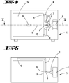
- the Figures 4 and 5 show a further embodiment in which the coupling element 3 is also designed as a four-armed coupling pin.
- a coupling arm 4 is connected to a plurality of decoupling arms 5, 6, 7.
- Each decoupling arm 5, 6, 7 is connected to a waveguide 8, 9, 10.
- the waveguide 8 opens out on a side wall of the cooking space 14 in its upper region and forms a feed point 11.
- the waveguide 9 opens out on the rear side of the cooking chamber 14 at a feed point 12.
- the waveguide 10 opens below the feed point 11 of the waveguide 8 at a feed point 13 into the cooking space 14.
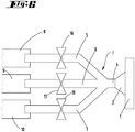
- the total of three decoupling branches 5, 6, 7, which are connected together with an in-coupling branch 4, can optionally be brought from a power-transmitting functional position to a non-power-transmitting functional position.
- suitable switching means 16, 17, 18 are provided with which the power transmission from the coupling-in end of the coupling-out branch 5, 6, 7 to the coupling-out end of the coupling-out branch 5, 6, 7 can be interrupted.
- alternating electromagnetic fields can be coupled into the cooking chamber 14 at spatially different feed points 11, 12, 13. It can be polarized or non-polarized alternating electromagnetic fields.
- the feed points 11, 12, 13 are arranged at selected points on the walls of the cooking chamber 14 in such a way that the electromagnetic waves are superimposed neither 100 percent constructively nor 100 percent destructively.
- electromagnetic alternating fields can be fed into the cooking chamber 14 at different feed points 11, 12, 13 in successive steps. It is also possible to use different groups of feed points 11, 12, 13 for feeding in the heating power.
- the coupling element 3 can be an electrically conductive solid body into which electromagnetic microwaves are fed will.
- the solid forks into several decoupling branches 5, 6, 7. Through this branching, the microwaves are divided into several outputs.
- the decoupling branches 5, 6, 7 are preferably each connected to a waveguide 8, 9, 10, which guide the microwaves to the feed points 11, 12, 13.
- the coupling element 3 can, however, also have a different physical design. What is essential is its electrotechnical property of dividing power coupled into a coupling branch 4 over several coupling branches 5, 6, 7.
- the coupling element 3 can thus also be designed as a branching waveguide. Each decoupling branch 5, 6, 7 can merge into a waveguide 8 which opens into the cooking chamber 14 at the feed point 11, 12, 13.
- the switching elements identified by the reference numbers 16, 17, 18 can block the power transmission through a decoupling branch 5, 6, 7. However, it is also possible to merely reduce the power transmission through a decoupling branch 5, 6, 7, so that the electromagnetic power coupled into the coupling branch 4 can be transmitted to the decoupling branches 5, 6, 7 in varying proportions.
Description
- Die Erfindung betrifft eine Vorrichtung zum Einspeisen eines von einem Mikrowellensender erzeugten elektromagnetischen Wechselfeldes in einen Garraum eines Mikrowellenherdes, wobei das elektromagnetische Wechselfeld in einer Leistungsflussrichtung mittels einer Übertragungseinrichtung vom Mikrowellensender an mehrere Einspeisepunkte des Garraums übertragen wird, an denen die vom Mikrowellensender erzeugte elektromagnetische Leistung in den Garraum eingespeist wird, wobei die Übertragungseinrichtung mindestens einen Hohlleiter und ein an den Hohlleiter gekoppeltes Kopplungselement aufweist, wobei das als Leistungsverteiler ausgebildete Kopplungselement den Mikrowellensender mit mehreren Hohlleitern verbindet.
- Die Erfindung betrifft darüber hinaus ein Verfahren zum Betrieb einer derartigen Vorrichtung.
- Vorrichtungen zum Einspeisen elektromagnetischer Wechselfelder in einem Garraum sind unter der Bezeichnung "Mikrowellenherde" bekannt. Das elektromagnetische Wechselfeld wird von einem Mikrowellensender erzeugt, der hierzu einen Magnetron aufweist. Die Mikrowellen werden über einen Auskoppelabschnitt an ein Kopplungselement übertragen. Das Kopplungselement koppelt das elektromagnetische Wechselfeld an einen Hohlleiter an, der in den Garraum mündet. Das Kopplungselement und der Auskoppelabschnitt können dabei einen Impedanzwandler ausbilden. Innerhalb des Garraums bereiten sich die elektromagnetischen Wellen in Richtung ihrer Abstrahlrichtung an den Einspeisepunkten aus und werden von den Wänden mehrfach reflektiert. Es bildet sich keine homogene Feldverteilung innerhalb des Garraums aus, so dass die Erwärmung von Speisen innerhalb des Garraums nicht homogen erfolgt. Im Garraum entstehende stehende Wellen überlagern sich destruktiv bzw. konstruktiv. Es verbleiben heiße bzw. kalte Stellen.
- Um die Energiebeaufschlagung der aufzuwärmenden Speisen zu homogenisieren, wurden mechanische Störglieder vorgesehen, in der Art eines Deckenventilators, mit denen zeitlich sich verändernde Reflektionsflächen geschaffen worden sind.
- Die
EP 0 284 958 A1 schlägt eine Vorrichtung zum Einkoppeln eines Mikrowellenfeldes an einem Mikrowellenherd vor, bei dem innerhalb eines Resonatorraums Koppelstifte vorgesehen sind, die eine Drehung des in den Resonatorraum eingekoppelten elektromagnetischen Feldes verursachen sollen, so dass aus einer Einspeiseöffnung unpolarisiertes Wechselfeld austreten kann. Dort wird ebenfalls vorgeschlagen, zwei Sender mit jeweils einem Hohlleiter an einen gemeinsamen Resonatorraum anzuschließen, der seinerseits über mehrere Kopplungsöffnungen an den Garraum gekoppelt ist. - Des Weiteren sind aus den Veröffentlichungen
EP 2445312 A1 ,EP 3151636 A1 ,JP 2008/269794 A FR 1378280 A - Der Erfindung liegt die Aufgabe zugrunde, Maßnahmen vorzuschlagen, mit denen das zu erwärmende Gargut gleichmäßiger erhitzt wird und dadurch eine homogenere Temperaturverteilung aufweist.
- Gelöst wird die Aufgabe durch die in den Ansprüchen angegebene Erfindung.
- Die Übertragungseinrichtung, mit der das elektromagnetische Wechselfeld und damit die vom Mikrowellensender erzeugte Leistung vom Mikrowellensender zu den Einspeisepunkten übertragen wird, weist ein Kopplungselement und mehrere Hohlleiter auf, wobei das Kopplungselement ein mehrere Arme aufweisender Kopplungsstift ist. Das elektromagnetische Wechselfeld wird in das Kopplungselement eingespeist und mit seiner Hilfe auf mehrere Hohlleiter aufgeteilt, so dass es auf mehreren, unterschiedlichen Wegen in den Garraum geleitet werden kann, da jeder Hohlleiter an einem ihm individuell zugeordneten Einspeisepunkt in den Garraum mündet. Das elektromagnetische Wechselfeld wird bspw. mit in einem Magnetron erzeugt und bspw. in einen Einkopplungszweig des Kopplungselementes eingespeist. Das Kopplungselement kann mehrere Auskopplungszweige besitzen, die die in das Kopplungselement eingespeiste Leistung auf die mehreren Hohlleiter aufteilen. Dies kann gemäß einem vorgegebenen Leistungsaufteilungsverhältnis erfolgen. Bevorzugt wird die in dem Einkopplungszweig eingekoppelte Leistung gleichmäßig auf alle Auskopplungszweige übertragen. Das Kopplungselement kann von einem elektrisch leitenden Körper, insbesondere von einem Metallkörper ausgebildet sein. Ein Arm des Kopplungselementes wirkt als Einkopplungszweig. Mehrere andere Arme des Kopplungselementes wirken als Auskopplungszweige. Das Kopplungselement bildet eine Weiche aus, mit der von einer einzigen Quelle erzeugte elektromagnetische Wellen auf mehrere Ausgänge verteilt werden können. Jedem Ausgang ist bevorzugt ein Einspeisepunkt zugeordnet. Die Einspeisepunkte sind bevorzugt an zumindest zwei in einem Winkel zueinander stehenden Wänden des Garraums angeordnet. Als Folge dieser Ausgestaltung, die insbesondere mehrere seitliche Einspeisepunkte aufweist, ist es möglich, die im Stand der Technik auftretenden, durch eine Überlagerung der Feldstärken entstehenden konstruktiven und destruktiven Überlagerungen derart zu beeinflussen, dass sich die elektromagnetischen Wellen im Wesentlichen nicht gegenseitig auslöschen bzw. zu 100 Prozent additiv überlagern, so dass sich mit der erfindungsgemäßen Vorrichtung die Bildung von kalten und heißen Zonen innerhalb des Gargutes vermindern lässt. Hierzu ist es besonders vorteilhaft, wenn drei oder mehr Einspeisepunkte vorgesehen sind, die in geeigneter geometrischer Anordnung an den Wänden des Garraums angeordnet sind. In einer Weiterbildung der Erfindung ist vorgesehen, dass das Kopplungselement als Mehrwegeweiche ausgebildet ist. Die einzelnen Auskopplungszweige können auch in Bezug auf den Einkopplungszweig von einer leistungsübertragenden Funktionsstellung in eine nicht leistungsübertragende Funktionsstellung gebracht werden. Hierdurch ist es möglich, in einer zeitlichen Abfolge die Leistung durch verschiedene Einspeisepunkte in den Garraum einzuspeisen, wobei insbesondere auch vorgesehen ist, dass die elektromagnetischen Wechselfelder nacheinander durch unterschiedliche Gruppen von Einspeisepunkten in den Garraum eingespeist werden. Die Einspeisepunkte können durch Öffnungen verwirklicht sein, an denen jeweils ein Hohlleiter in den Garraum mündet. Hierdurch können einzelne Zonen oder Strahlungspfade innerhalb des Garraums zeitlich gesteuert nacheinander mit Mikrowellen-Energie versorgt werden.
- Ausführungsbeispiele der Erfindung werden nachfolgend anhand beigefügter Zeichnungen erläutert. Es zeigen:
- Fig. 1
- in einer perspektivischen Darstellung einen Mikrowellenherd gemäß Stand der Technik,
- Fig. 2
- in einer Draufsicht schematisch einen Mikrowellenherd gemäß Stand der Technik,
- Fig. 3
- ein erstes Ausführungsbeispiel der Erfindung schematisch in einer Ansicht,
- Fig. 4
- ein zweites Ausführungsbeispiel der Erfindung schematisch in einer Ansicht,
- Fig. 5
- das in
Figur 4 dargestellte Ausführungsbeispiel, jedoch etwa entlang der Schnittlinie V-V inFigur 4 und - Fig. 6
- ein Kopplungsglied eines dritten Ausführungsbeispiels.
- Die
Figur 1 zeigt einen Mikrowellenherd gemäß Stand der Technik, bei dem innerhalb eines Gehäuses ein von Wänden begrenzter Garraum 14 vorgesehen ist, in den an einer Einspeisestelle ein Hohlleiter 8 mündet, in dem Leistung in Form eines elektromagnetischen Wechselfeldes eingekoppelt ist. Das elektromagnetische Wechselfeld wird in einem Magnetron 1 erzeugt und über einen Auskoppelabschnitt 2 in den Hohlleiter 8 eingekoppelt. Innerhalb des Garraums 14 findet eine Mehrfachreflektion des sich ausbreitenden elektromagnetischen Wechselfeldes statt. Die mit dem elektromagnetischen Wechselfeld transportierte Energie wird innerhalb des Gargutes in Wärme umgewandelt. Zur Homogenisierung der Feldverteilung ist an der Decke des Garraums 14 ein Schaufelrad angeordnet. - Die
Figur 2 zeigt einen weiteren Mikrowellenherd des Standes der Technik, bei dem das von einem Mikrowellensender 1, 2 erzeugte elektromagnetische Wechselfeld in ein Kopplungselement 3 in Form eines Kopplungsstiftes eingekoppelt wird. Das Kopplungselement 3 überträgt die vom Mikrowellensender 1, 2 erzeugte elektromagnetische Leistung an einen Hohlleiter 8, in dem die Leistung als elektromagnetische Strahlung zu einer Öffnung in der Wand des Garraums 14 transportiert wird, die einen Einspeisepunkt 11 darstellt. - Die in der
Figur 3 dargestellte erste Ausführungsform der Erfindung besitzt ein Kopplungselement 3, das gabelförmig ausgebildet ist. Es besitzt vier Arme. Einen kurzen Einkopplungsarm 4, der sich in drei Auskopplungsarme 5, 6, 7 verzweigt. Die in den Einkopplungsarm 4 eingekoppelte elektromagnetische Leistung wird gleichmäßig in die Auskopplungsarme 5, 6, 7 überragen. Die Enden der Auskopplungsarme 5, 6, 7 bilden lokale Quellen für ein elektromagnetisches Wechselfeld, welches jeweils auf einen Hohlleiter 8, 9, 10 übertragen wird. Die Hohlleiter 8, 9, 10 münden an voneinander verschiedenen Orten in den Garraum 14. Bei dem in derFigur 3 dargestellten Ausführungsbeispiel münden die Hohlleiter 8, 9, 10 an drei in einer Seitenwand an verschiedenen Stellen liegenden Einspeisepunkten 11, 12, 13. - Die
Figuren 4 und 5 zeigen ein weiteres Ausführungsbeispiel, bei dem das Kopplungselement 3 ebenfalls als insgesamt vierarmiger Kopplungsstift ausgebildet ist. Ein Einkopplungsarm 4 ist mit mehreren Auskopplungsarmen 5, 6, 7 verbunden. Jeder Auskopplungsarm 5, 6, 7 ist mit einem Hohlleiter 8, 9, 10 verbunden. Der Hohlleiter 8 mündet an einer Seitenwand des Garraums 14 in dessen oberen Bereich und bildet einen Einspeisepunkt 11 aus. Der Hohlleiter 9 mündet auf der Rückseite des Garraums 14 an einem Einspeisepunkt 12. Der Hohlleiter 10 mündet unterhalb des Einspeisepunktes 11 des Hohlleiters 8 an einem Einspeisepunkt 13 in den Garraum 14. - Bei der in der
Figur 6 dargestellten Ausführungsform können die insgesamt drei Auskopplungszweige 5, 6, 7, die zusammen mit einem Einkopplungszweig 4 verbunden sind, wahlweise von einer leistungsübertragenden Funktionsstellung in eine nicht leistungsübertragende Funktionsstellung gebracht werden. Hierzu sind geeignete Schaltmittel 16,17,18 vorgesehen, mit denen die Leistungsübertragung vom einkoppelnden Ende des Auskopplungszweiges 5, 6, 7 zum auskoppelnden Ende des Auskopplungszweiges 5, 6, 7 unterbrochen werden kann. - Mit der erfindungsgemäßen Vorrichtung können an räumlich voneinander verschiedenen Einspeisepunkten 11, 12, 13 elektromagnetische Wechselfelder in den Garraum 14 eingekoppelt werden. Es kann sich dabei um polarisierte oder nicht polarisierte elektromagnetische Wechselfelder handeln. Die Einspeisepunkte 11, 12, 13 sind derart an ausgewählten Stellen der Wände des Garraums 14 angeordnet, dass sich die elektromagnetischen Wellen weder zu 100 Prozent konstruktiv noch zu 100 Prozent destruktiv überlagern.
- Mittels der Schaltelemente 16, 17, 18, die gewissermaßen die Funktion von Ventilen aufweisen, lassen sich in zeitlich aufeinander folgenden Schritten elektromagnetische Wechselfelder an unterschiedlichen Einspeisepunkten 11, 12,13 in den Garraum 14 einspeisen. Es ist auch möglich, jeweils unterschiedliche Gruppen von Einspeisepunkten 11, 12, 13 für die Einspeisung der Heizleistung zu verwenden.
- Bei dem Kopplungselement 3 kann es sich um einen elektrisch leitenden Festkörper handeln, in den elektromagnetische Mikrowellen eingespeist werden. Der Festkörper gabelt sich in mehrere Auskopplungszweige 5, 6, 7 auf. Durch diese Verzweigung werden die Mikrowellen auf mehrere Ausgänge aufgeteilt. Die Auskopplungszweige 5, 6, 7 sind bevorzugt jeweils mit einem Hohlleiter 8, 9, 10 verbunden, die die Mikrowellen zu den Einspeisepunkten 11, 12, 13 leiten.
- Das Kopplungselement 3 kann aber auch körperlich anders ausgebildet sein. Wesentlich ist seine elektrotechnische Eigenschaft, in einen Einkopplungszweig 4 eingekoppelte Leistung auf mehrere Auskopplungszweige 5, 6, 7 aufzuteilen. Das Kopplungselement 3 kann somit auch als sich verzweigender Hohlleiter ausgebildet sein. Jeder Auskopplungszweig 5, 6, 7 kann in einen Hohlleiter 8 übergehen, der am Einspeisepunkt 11,12,13 in den Garraum 14 mündet.
- Die mit den Bezugsziffern 16, 17, 18 bezeichneten Schaltelemente können die Leistungsübertragung durch einen Auskopplungszweig 5, 6, 7 sperren. Es ist aber auch möglich, die Leistungsübertragung durch einen Auskopplungszweig 5, 6, 7 lediglich zu vermindern, so dass die in den Einkopplungszweig 4 eingekoppelte elektromagnetische Leistung in variierenden Verhältnissen auf die Auskopplungszweige 5, 6, 7 übertragen werden kann.
-
- 1
- Mikrowellensender
- 2
- Mikrowellensender
- 3
- Kopplungselement
- 4
- Einkoppelzweig
- 5
- Auskoppelzweig
- 6
- Auskoppelzweig
- 7
- Auskoppelzweig
- 8
- Hohlleiter
- 9
- Hohlleiter
- 10
- Hohlleiter
- 11
- Einspeisepunkt
- 12
- Einspeisepunkt
- 13
- Einspeisepunkt
- 14
- Garraum
- 15
- Gehäuse
- 16
- Schaltelement
- 17
- Schaltelement
- 18
- Schaltelement
Claims (9)
- Vorrichtung zum Einspeisen eines von einem Mikrowellensender (1, 2) erzeugten elektromagnetischen Wechselfeldes in einen Garraum (14) eines Mikrowellenherdes, wobei das elektromagnetische Wechselfeld in einer Leistungsflussrichtung mittels einer Übertragungseinrichtung vom Mikrowellensender (1, 2) an mehrere Einspeisepunkte (11, 12, 13) des Garraums (14) übertragen wird, an denen die vom Mikrowellensender (1, 2) erzeugte Leistung in den Garraum (14) eingespeist wird, wobei die Übertragungseinrichtung mindestens einen Hohlleiter (8, 9, 10) und ein an den Hohlleiter (8, 9,10) gekoppeltes Kopplungselement (3) aufweist, wobei das als Leistungsverteiler ausgebildete Kopplungselement (3) den Mikrowellensender (1, 2) mit mehreren Hohlleitern (8, 9, 10) verbindet, dadurch gekennzeichnet, dass das Kopplungselement (3) ein mehrere Arme aufweisender Kopplungsstift ist.
- Vorrichtung nach Anspruch 1, dadurch gekennzeichnet, dass das Kopplungselement (3) einen Einkopplungszweig (4) aufweist, in den das elektromagnetische Wechselfeld eingekoppelt wird und mehrere Auskopplungszweige (5, 6, 7), auf die die in den Einkopplungszweig (4) eingespeiste Leistung verteilt wird.
- Vorrichtung nach Anspruch 2, dadurch gekennzeichnet, dass die in den Einkopplungszweig (4) eingekoppelte elektromagnetische Leistung im Wesentlichen gleichmäßig auf die mehreren Auskopplungszweige (5, 6, 7) verteilt wird.
- Vorrichtung nach Anspruch 2 oder 3, dadurch gekennzeichnet, dass jeder Auskopplungszweig (5, 6, 7), insbesondere jeder als Arm ausgebildeter Auskopplungszweig (5, 6, 7) mit einem ihm individuell zugeordneten Hohlleiter (8, 9,10) wirkverbunden ist.
- Vorrichtung nach einem der vorhergehenden Ansprüche, dadurch gekennzeichnet, dass die Einspeisepunkte (11, 12, 13) an mindestens zwei voneinander verschiedenen Wänden des Garraums (14) angeordnet sind.
- Vorrichtung nach einem der Ansprüche 2 bis 5, gekennzeichnet durch Schaltelemente (16,17,18), mit denen die Auskopplungszweige (5, 6, 7) individuell von einer leistungsübertragenden Funktionsstellung gegenüber dem Einkopplungszweig (4) in eine nicht leistungsübertragende Funktionsstellung zum Einkopplungszweig (4) bringbar ist.
- Vorrichtung nach Anspruch 6, dadurch gekennzeichnet, dass die Schaltelemente (16, 17, 18) derart ausgebildet sind, dass die über die Auskopplungszweige (5, 6, 7) ausgekoppelten Leistungen variierbar sind.
- Verfahren zum Betrieb einer Vorrichtung gemäß einem der vorhergehenden Ansprüche, wobei die vom Mikrowellensender (1, 2) erzeugte elektromagnetische Leistung mittels eines Kopplungselementes (3) auf jeweils an einem Einspeisepunkt (11, 12, 13) in den Garraum mündenden Hohlleiter (8, 9,10) übertragen wird, dadurch gekennzeichnet, dass die Leistungsübertragung mittels des Kopplungselementes (3) über einen mehrere Arme aufweisenden Kopplungsstift erfolgt.
- Verfahren nach Anspruch 8, dadurch gekennzeichnet, dass mittels Schaltelementen (16, 17, 18) in zeitlicher Aufeinanderfolge die in das Kopplungselement (3) eingespeiste Leistung auf eine Unteranzahl der Hohlleiter (8, 9,10) verteilt oder variiert wird.
Priority Applications (5)
| Application Number | Priority Date | Filing Date | Title |
|---|---|---|---|
| ES17187390T ES2844648T3 (es) | 2017-08-23 | 2017-08-23 | Dispositivo de alimentación de microondas en un horno de microondas |
| PL17187390T PL3448121T3 (pl) | 2017-08-23 | 2017-08-23 | Urządzenie zasilające mikrofalami w kuchence mikrofalowej |
| EP17187390.4A EP3448121B1 (de) | 2017-08-23 | 2017-08-23 | Mikrowelleneinspeisevorrichtung an einem mikrowellenherd |
| CN201810959000.2A CN109429401A (zh) | 2017-08-23 | 2018-08-22 | 在微波炉上的微波馈入设备 |
| US16/108,586 US20190069354A1 (en) | 2017-08-23 | 2018-08-22 | Microwave feed device on a microwave oven |
Applications Claiming Priority (1)
| Application Number | Priority Date | Filing Date | Title |
|---|---|---|---|
| EP17187390.4A EP3448121B1 (de) | 2017-08-23 | 2017-08-23 | Mikrowelleneinspeisevorrichtung an einem mikrowellenherd |
Publications (2)
| Publication Number | Publication Date |
|---|---|
| EP3448121A1 EP3448121A1 (de) | 2019-02-27 |
| EP3448121B1 true EP3448121B1 (de) | 2020-12-23 |
Family
ID=59745715
Family Applications (1)
| Application Number | Title | Priority Date | Filing Date |
|---|---|---|---|
| EP17187390.4A Active EP3448121B1 (de) | 2017-08-23 | 2017-08-23 | Mikrowelleneinspeisevorrichtung an einem mikrowellenherd |
Country Status (5)
| Country | Link |
|---|---|
| US (1) | US20190069354A1 (de) |
| EP (1) | EP3448121B1 (de) |
| CN (1) | CN109429401A (de) |
| ES (1) | ES2844648T3 (de) |
| PL (1) | PL3448121T3 (de) |
Family Cites Families (14)
| Publication number | Priority date | Publication date | Assignee | Title |
|---|---|---|---|---|
| FR1378280A (fr) * | 1963-10-04 | 1964-11-13 | Procédé et dispositif d'excitation d'un four de chauffage à ondes d'hyperfréquence | |
| SE387815B (sv) * | 1974-12-18 | 1976-09-13 | Husqvarna Ab | Mikrovagsapplikator |
| CH674563A5 (de) * | 1987-03-24 | 1990-06-15 | Gigatherm Mikrowellen Ag | |
| DE4027777A1 (de) * | 1990-09-01 | 1992-03-05 | Kueppersbusch | Mikrowellenofen |
| CN1826026A (zh) * | 2005-02-24 | 2006-08-30 | 厦门灿坤实业股份有限公司 | 均匀辐射的微波加热方法及装置 |
| CN101282600B (zh) * | 2007-04-06 | 2010-09-15 | 财团法人食品工业发展研究所 | 连续式微波加热装置 |
| JP4992525B2 (ja) * | 2007-04-16 | 2012-08-08 | パナソニック株式会社 | マイクロ波処理装置 |
| EP2445312B1 (de) * | 2010-10-22 | 2017-02-22 | Whirlpool Corporation | Mikrowellenheizvorrichtung und Verfahren zum Betreiben einer derartigen Mikrowellenheizvorrichtung |
| CN102374557B (zh) * | 2011-10-31 | 2016-08-03 | 广东美的厨房电器制造有限公司 | 半导体微波炉的微波馈入结构 |
| EP3300456B1 (de) * | 2012-03-14 | 2020-05-06 | Microwave Materials Technologies, Inc. | Verbessertes mikrowellen-heizverfahren |
| JP2017525121A (ja) * | 2014-05-28 | 2017-08-31 | グァンドン ミデア キッチン アプライアンシズ マニュファクチュアリング カンパニー リミテッド | 半導体電子レンジ及びその半導体マイクロ波源 |
| CN104676670A (zh) * | 2014-05-28 | 2015-06-03 | 广东美的厨房电器制造有限公司 | 半导体微波炉及其半导体微波源 |
| CN104902604B (zh) * | 2015-06-08 | 2016-11-30 | 广东美的厨房电器制造有限公司 | 波导组件和微波饭煲 |
| US11057969B2 (en) * | 2016-12-27 | 2021-07-06 | Whirlpool Corporation | Low cost solid state RF generation system for electromagnetic cooking |
-
2017
- 2017-08-23 EP EP17187390.4A patent/EP3448121B1/de active Active
- 2017-08-23 PL PL17187390T patent/PL3448121T3/pl unknown
- 2017-08-23 ES ES17187390T patent/ES2844648T3/es active Active
-
2018
- 2018-08-22 CN CN201810959000.2A patent/CN109429401A/zh active Pending
- 2018-08-22 US US16/108,586 patent/US20190069354A1/en not_active Abandoned
Non-Patent Citations (1)
| Title |
|---|
| None * |
Also Published As
| Publication number | Publication date |
|---|---|
| CN109429401A (zh) | 2019-03-05 |
| PL3448121T3 (pl) | 2021-06-14 |
| ES2844648T3 (es) | 2021-07-22 |
| EP3448121A1 (de) | 2019-02-27 |
| US20190069354A1 (en) | 2019-02-28 |
Similar Documents
| Publication | Publication Date | Title |
|---|---|---|
| DE1027274B (de) | Leiter zur UEbertragung elektromagnetischer H-Wellen | |
| DE10139071A1 (de) | Wandlervorrichtung | |
| DE112015000981T5 (de) | Mikrowellen-Behandlungsvorrichtung | |
| EP3448121B1 (de) | Mikrowelleneinspeisevorrichtung an einem mikrowellenherd | |
| EP3307018B1 (de) | Verfahren zur steuerung eines induktionskochfeldes und induktionskochfeld | |
| EP3598848A1 (de) | Heizeinrichtung für ein kochfeld und kochfeld | |
| DE2807813C2 (de) | Schaltungsanordnung zur Erreichung von Leistungsanpassung bei rauschangepaBten Hochfrequenz-Verstärkern | |
| DE3029035C2 (de) | Mikrowellenheizgerät | |
| DE4412943A1 (de) | Gar- und/oder Kochgerät, welches für eine bodenseitige Zuführung von Wärmeenergie durch Wärmeleitung oder durch elektromagnetische Induktion eingerichtet ist | |
| DE1264545C2 (de) | Verteilerschaltung fuer vier im Drehfeld gespeiste Strahler | |
| DE102010002753B4 (de) | Plasmaversorgungsanordnung mit mehreren Leistungskopplungsstufen | |
| EP2933513A1 (de) | Kupplungsvorrichtung zur Anbindung einer Schaltkupplung an einen Turbinenstrang | |
| WO2022048839A1 (de) | Kochfeldvorrichtung und verfahren zum betrieb einer kochfeldvorrichtung | |
| EP0351514A2 (de) | Hohlleiter-Twist | |
| DE102012210852A1 (de) | Kochfeld bzw. Gargerät mit einem Kochfeld und einer elektrischen Versorgungsleitung | |
| DE4038817C1 (de) | ||
| DE102015104523A1 (de) | Verfahren zur Steuerung eines Mikrowellen-Gargeräts sowie Mikrowellen-Gargerät | |
| DE102018205970A1 (de) | Heizkörper für ein Gargerät und Gargerät | |
| DE855581C (de) | Umlaufender Verteiler fuer Ultrakurzwellen | |
| DE603671C (de) | Einrichtung zur Verbesserung der Wirtschaftlichkeit in Turbinenanlagen mit zeitweiseschwacher Belastung, insbesondere bei Marschfahrt von Schiffen | |
| EP1932205A1 (de) | Gleichspannungs- und/oder nf-auskopplung aus einer hf-strecke | |
| DE757273C (de) | Anordnung zur Anpassung einer Hochfrequenzleitung an eine Belastung | |
| EP1253669B1 (de) | Gruppenantenne mit einer Anzahl von Resonanz-Strahlerelementen | |
| DE2623062C2 (de) | Verteilerleitung für die Druckmittelversorgung von Verbrauchern, insbesondere hydraulischen Verbrauchern in untertägigen Gewinnungsbetrieben | |
| DE2612789C3 (de) | Mehrfachkoppler für Mikrowellen |
Legal Events
| Date | Code | Title | Description |
|---|---|---|---|
| PUAI | Public reference made under article 153(3) epc to a published international application that has entered the european phase |
Free format text: ORIGINAL CODE: 0009012 |
|
| STAA | Information on the status of an ep patent application or granted ep patent |
Free format text: STATUS: THE APPLICATION HAS BEEN PUBLISHED |
|
| AK | Designated contracting states |
Kind code of ref document: A1 Designated state(s): AL AT BE BG CH CY CZ DE DK EE ES FI FR GB GR HR HU IE IS IT LI LT LU LV MC MK MT NL NO PL PT RO RS SE SI SK SM TR |
|
| AX | Request for extension of the european patent |
Extension state: BA ME |
|
| STAA | Information on the status of an ep patent application or granted ep patent |
Free format text: STATUS: REQUEST FOR EXAMINATION WAS MADE |
|
| 17P | Request for examination filed |
Effective date: 20190731 |
|
| RBV | Designated contracting states (corrected) |
Designated state(s): AL AT BE BG CH CY CZ DE DK EE ES FI FR GB GR HR HU IE IS IT LI LT LU LV MC MK MT NL NO PL PT RO RS SE SI SK SM TR |
|
| GRAP | Despatch of communication of intention to grant a patent |
Free format text: ORIGINAL CODE: EPIDOSNIGR1 |
|
| STAA | Information on the status of an ep patent application or granted ep patent |
Free format text: STATUS: GRANT OF PATENT IS INTENDED |
|
| INTG | Intention to grant announced |
Effective date: 20200717 |
|
| GRAS | Grant fee paid |
Free format text: ORIGINAL CODE: EPIDOSNIGR3 |
|
| GRAA | (expected) grant |
Free format text: ORIGINAL CODE: 0009210 |
|
| STAA | Information on the status of an ep patent application or granted ep patent |
Free format text: STATUS: THE PATENT HAS BEEN GRANTED |
|
| AK | Designated contracting states |
Kind code of ref document: B1 Designated state(s): AL AT BE BG CH CY CZ DE DK EE ES FI FR GB GR HR HU IE IS IT LI LT LU LV MC MK MT NL NO PL PT RO RS SE SI SK SM TR |
|
| REG | Reference to a national code |
Ref country code: GB Ref legal event code: FG4D Free format text: NOT ENGLISH |
|
| REG | Reference to a national code |
Ref country code: DE Ref legal event code: R096 Ref document number: 502017008746 Country of ref document: DE |
|
| REG | Reference to a national code |
Ref country code: AT Ref legal event code: REF Ref document number: 1348961 Country of ref document: AT Kind code of ref document: T Effective date: 20210115 |
|
| REG | Reference to a national code |
Ref country code: IE Ref legal event code: FG4D Free format text: LANGUAGE OF EP DOCUMENT: GERMAN |
|
| PG25 | Lapsed in a contracting state [announced via postgrant information from national office to epo] |
Ref country code: GR Free format text: LAPSE BECAUSE OF FAILURE TO SUBMIT A TRANSLATION OF THE DESCRIPTION OR TO PAY THE FEE WITHIN THE PRESCRIBED TIME-LIMIT Effective date: 20210324 Ref country code: FI Free format text: LAPSE BECAUSE OF FAILURE TO SUBMIT A TRANSLATION OF THE DESCRIPTION OR TO PAY THE FEE WITHIN THE PRESCRIBED TIME-LIMIT Effective date: 20201223 Ref country code: RS Free format text: LAPSE BECAUSE OF FAILURE TO SUBMIT A TRANSLATION OF THE DESCRIPTION OR TO PAY THE FEE WITHIN THE PRESCRIBED TIME-LIMIT Effective date: 20201223 Ref country code: NO Free format text: LAPSE BECAUSE OF FAILURE TO SUBMIT A TRANSLATION OF THE DESCRIPTION OR TO PAY THE FEE WITHIN THE PRESCRIBED TIME-LIMIT Effective date: 20210323 |
|
| REG | Reference to a national code |
Ref country code: NL Ref legal event code: MP Effective date: 20201223 |
|
| PG25 | Lapsed in a contracting state [announced via postgrant information from national office to epo] |
Ref country code: SE Free format text: LAPSE BECAUSE OF FAILURE TO SUBMIT A TRANSLATION OF THE DESCRIPTION OR TO PAY THE FEE WITHIN THE PRESCRIBED TIME-LIMIT Effective date: 20201223 Ref country code: BG Free format text: LAPSE BECAUSE OF FAILURE TO SUBMIT A TRANSLATION OF THE DESCRIPTION OR TO PAY THE FEE WITHIN THE PRESCRIBED TIME-LIMIT Effective date: 20210323 Ref country code: LV Free format text: LAPSE BECAUSE OF FAILURE TO SUBMIT A TRANSLATION OF THE DESCRIPTION OR TO PAY THE FEE WITHIN THE PRESCRIBED TIME-LIMIT Effective date: 20201223 |
|
| PG25 | Lapsed in a contracting state [announced via postgrant information from national office to epo] |
Ref country code: NL Free format text: LAPSE BECAUSE OF FAILURE TO SUBMIT A TRANSLATION OF THE DESCRIPTION OR TO PAY THE FEE WITHIN THE PRESCRIBED TIME-LIMIT Effective date: 20201223 Ref country code: HR Free format text: LAPSE BECAUSE OF FAILURE TO SUBMIT A TRANSLATION OF THE DESCRIPTION OR TO PAY THE FEE WITHIN THE PRESCRIBED TIME-LIMIT Effective date: 20201223 |
|
| REG | Reference to a national code |
Ref country code: LT Ref legal event code: MG9D |
|
| REG | Reference to a national code |
Ref country code: ES Ref legal event code: FG2A Ref document number: 2844648 Country of ref document: ES Kind code of ref document: T3 Effective date: 20210722 |
|
| PG25 | Lapsed in a contracting state [announced via postgrant information from national office to epo] |
Ref country code: SK Free format text: LAPSE BECAUSE OF FAILURE TO SUBMIT A TRANSLATION OF THE DESCRIPTION OR TO PAY THE FEE WITHIN THE PRESCRIBED TIME-LIMIT Effective date: 20201223 Ref country code: RO Free format text: LAPSE BECAUSE OF FAILURE TO SUBMIT A TRANSLATION OF THE DESCRIPTION OR TO PAY THE FEE WITHIN THE PRESCRIBED TIME-LIMIT Effective date: 20201223 Ref country code: PT Free format text: LAPSE BECAUSE OF FAILURE TO SUBMIT A TRANSLATION OF THE DESCRIPTION OR TO PAY THE FEE WITHIN THE PRESCRIBED TIME-LIMIT Effective date: 20210423 Ref country code: EE Free format text: LAPSE BECAUSE OF FAILURE TO SUBMIT A TRANSLATION OF THE DESCRIPTION OR TO PAY THE FEE WITHIN THE PRESCRIBED TIME-LIMIT Effective date: 20201223 Ref country code: CZ Free format text: LAPSE BECAUSE OF FAILURE TO SUBMIT A TRANSLATION OF THE DESCRIPTION OR TO PAY THE FEE WITHIN THE PRESCRIBED TIME-LIMIT Effective date: 20201223 Ref country code: SM Free format text: LAPSE BECAUSE OF FAILURE TO SUBMIT A TRANSLATION OF THE DESCRIPTION OR TO PAY THE FEE WITHIN THE PRESCRIBED TIME-LIMIT Effective date: 20201223 Ref country code: LT Free format text: LAPSE BECAUSE OF FAILURE TO SUBMIT A TRANSLATION OF THE DESCRIPTION OR TO PAY THE FEE WITHIN THE PRESCRIBED TIME-LIMIT Effective date: 20201223 |
|
| REG | Reference to a national code |
Ref country code: DE Ref legal event code: R097 Ref document number: 502017008746 Country of ref document: DE |
|
| PG25 | Lapsed in a contracting state [announced via postgrant information from national office to epo] |
Ref country code: IS Free format text: LAPSE BECAUSE OF FAILURE TO SUBMIT A TRANSLATION OF THE DESCRIPTION OR TO PAY THE FEE WITHIN THE PRESCRIBED TIME-LIMIT Effective date: 20210423 |
|
| PG25 | Lapsed in a contracting state [announced via postgrant information from national office to epo] |
Ref country code: AL Free format text: LAPSE BECAUSE OF FAILURE TO SUBMIT A TRANSLATION OF THE DESCRIPTION OR TO PAY THE FEE WITHIN THE PRESCRIBED TIME-LIMIT Effective date: 20201223 |
|
| PLBE | No opposition filed within time limit |
Free format text: ORIGINAL CODE: 0009261 |
|
| STAA | Information on the status of an ep patent application or granted ep patent |
Free format text: STATUS: NO OPPOSITION FILED WITHIN TIME LIMIT |
|
| PG25 | Lapsed in a contracting state [announced via postgrant information from national office to epo] |
Ref country code: DK Free format text: LAPSE BECAUSE OF FAILURE TO SUBMIT A TRANSLATION OF THE DESCRIPTION OR TO PAY THE FEE WITHIN THE PRESCRIBED TIME-LIMIT Effective date: 20201223 |
|
| 26N | No opposition filed |
Effective date: 20210924 |
|
| PG25 | Lapsed in a contracting state [announced via postgrant information from national office to epo] |
Ref country code: SI Free format text: LAPSE BECAUSE OF FAILURE TO SUBMIT A TRANSLATION OF THE DESCRIPTION OR TO PAY THE FEE WITHIN THE PRESCRIBED TIME-LIMIT Effective date: 20201223 |
|
| PG25 | Lapsed in a contracting state [announced via postgrant information from national office to epo] |
Ref country code: MC Free format text: LAPSE BECAUSE OF FAILURE TO SUBMIT A TRANSLATION OF THE DESCRIPTION OR TO PAY THE FEE WITHIN THE PRESCRIBED TIME-LIMIT Effective date: 20201223 |
|
| REG | Reference to a national code |
Ref country code: BE Ref legal event code: MM Effective date: 20210831 |
|
| PG25 | Lapsed in a contracting state [announced via postgrant information from national office to epo] |
Ref country code: IS Free format text: LAPSE BECAUSE OF FAILURE TO SUBMIT A TRANSLATION OF THE DESCRIPTION OR TO PAY THE FEE WITHIN THE PRESCRIBED TIME-LIMIT Effective date: 20210423 Ref country code: LU Free format text: LAPSE BECAUSE OF NON-PAYMENT OF DUE FEES Effective date: 20210823 |
|
| PG25 | Lapsed in a contracting state [announced via postgrant information from national office to epo] |
Ref country code: IE Free format text: LAPSE BECAUSE OF NON-PAYMENT OF DUE FEES Effective date: 20210823 Ref country code: BE Free format text: LAPSE BECAUSE OF NON-PAYMENT OF DUE FEES Effective date: 20210831 |
|
| P01 | Opt-out of the competence of the unified patent court (upc) registered |
Effective date: 20230517 |
|
| PG25 | Lapsed in a contracting state [announced via postgrant information from national office to epo] |
Ref country code: CY Free format text: LAPSE BECAUSE OF FAILURE TO SUBMIT A TRANSLATION OF THE DESCRIPTION OR TO PAY THE FEE WITHIN THE PRESCRIBED TIME-LIMIT Effective date: 20201223 |
|
| PG25 | Lapsed in a contracting state [announced via postgrant information from national office to epo] |
Ref country code: HU Free format text: LAPSE BECAUSE OF FAILURE TO SUBMIT A TRANSLATION OF THE DESCRIPTION OR TO PAY THE FEE WITHIN THE PRESCRIBED TIME-LIMIT; INVALID AB INITIO Effective date: 20170823 |
|
| REG | Reference to a national code |
Ref country code: AT Ref legal event code: MM01 Ref document number: 1348961 Country of ref document: AT Kind code of ref document: T Effective date: 20220823 |
|
| PG25 | Lapsed in a contracting state [announced via postgrant information from national office to epo] |
Ref country code: AT Free format text: LAPSE BECAUSE OF NON-PAYMENT OF DUE FEES Effective date: 20220823 |
|
| PGFP | Annual fee paid to national office [announced via postgrant information from national office to epo] |
Ref country code: IT Payment date: 20230831 Year of fee payment: 7 Ref country code: GB Payment date: 20230824 Year of fee payment: 7 Ref country code: ES Payment date: 20230918 Year of fee payment: 7 Ref country code: CH Payment date: 20230902 Year of fee payment: 7 |
|
| PGFP | Annual fee paid to national office [announced via postgrant information from national office to epo] |
Ref country code: PL Payment date: 20230816 Year of fee payment: 7 Ref country code: FR Payment date: 20230821 Year of fee payment: 7 Ref country code: DE Payment date: 20230822 Year of fee payment: 7 |