EP3447298B1 - Dämpfungskörper zur verbindung eine vakuumpumpe - Google Patents
Dämpfungskörper zur verbindung eine vakuumpumpe Download PDFInfo
- Publication number
- EP3447298B1 EP3447298B1 EP17187107.2A EP17187107A EP3447298B1 EP 3447298 B1 EP3447298 B1 EP 3447298B1 EP 17187107 A EP17187107 A EP 17187107A EP 3447298 B1 EP3447298 B1 EP 3447298B1
- Authority
- EP
- European Patent Office
- Prior art keywords
- recipient
- side flange
- pump
- damping body
- flange
- Prior art date
- Legal status (The legal status is an assumption and is not a legal conclusion. Google has not performed a legal analysis and makes no representation as to the accuracy of the status listed.)
- Active
Links
Images


Classifications
-
- F—MECHANICAL ENGINEERING; LIGHTING; HEATING; WEAPONS; BLASTING
- F04—POSITIVE - DISPLACEMENT MACHINES FOR LIQUIDS; PUMPS FOR LIQUIDS OR ELASTIC FLUIDS
- F04D—NON-POSITIVE-DISPLACEMENT PUMPS
- F04D19/00—Axial-flow pumps
- F04D19/02—Multi-stage pumps
- F04D19/04—Multi-stage pumps specially adapted to the production of a high vacuum, e.g. molecular pumps
- F04D19/042—Turbomolecular vacuum pumps
-
- F—MECHANICAL ENGINEERING; LIGHTING; HEATING; WEAPONS; BLASTING
- F04—POSITIVE - DISPLACEMENT MACHINES FOR LIQUIDS; PUMPS FOR LIQUIDS OR ELASTIC FLUIDS
- F04D—NON-POSITIVE-DISPLACEMENT PUMPS
- F04D29/00—Details, component parts, or accessories
- F04D29/66—Combating cavitation, whirls, noise, vibration or the like; Balancing
- F04D29/661—Combating cavitation, whirls, noise, vibration or the like; Balancing especially adapted for elastic fluid pumps
- F04D29/668—Combating cavitation, whirls, noise, vibration or the like; Balancing especially adapted for elastic fluid pumps damping or preventing mechanical vibrations
-
- F—MECHANICAL ENGINEERING; LIGHTING; HEATING; WEAPONS; BLASTING
- F16—ENGINEERING ELEMENTS AND UNITS; GENERAL MEASURES FOR PRODUCING AND MAINTAINING EFFECTIVE FUNCTIONING OF MACHINES OR INSTALLATIONS; THERMAL INSULATION IN GENERAL
- F16L—PIPES; JOINTS OR FITTINGS FOR PIPES; SUPPORTS FOR PIPES, CABLES OR PROTECTIVE TUBING; MEANS FOR THERMAL INSULATION IN GENERAL
- F16L27/00—Adjustable joints; Joints allowing movement
- F16L27/10—Adjustable joints; Joints allowing movement comprising a flexible connection only
- F16L27/107—Adjustable joints; Joints allowing movement comprising a flexible connection only the ends of the pipe being interconnected by a flexible sleeve
- F16L27/11—Adjustable joints; Joints allowing movement comprising a flexible connection only the ends of the pipe being interconnected by a flexible sleeve the sleeve having the form of a bellows with multiple corrugations
- F16L27/111—Adjustable joints; Joints allowing movement comprising a flexible connection only the ends of the pipe being interconnected by a flexible sleeve the sleeve having the form of a bellows with multiple corrugations the bellows being reinforced
-
- F—MECHANICAL ENGINEERING; LIGHTING; HEATING; WEAPONS; BLASTING
- F04—POSITIVE - DISPLACEMENT MACHINES FOR LIQUIDS; PUMPS FOR LIQUIDS OR ELASTIC FLUIDS
- F04D—NON-POSITIVE-DISPLACEMENT PUMPS
- F04D29/00—Details, component parts, or accessories
- F04D29/60—Mounting; Assembling; Disassembling
- F04D29/64—Mounting; Assembling; Disassembling of axial pumps
- F04D29/644—Mounting; Assembling; Disassembling of axial pumps especially adapted for elastic fluid pumps
Definitions
- the present invention relates to a damping body for a vibration-decoupled connection of a vacuum pump, in particular a turbomolecular pump, to a recipient.
- a vibration-decoupled connection is required between a vacuum pump and a recipient if the recipient includes components, such as measuring arrangements, the operation of which would be disturbed by the vibrations of the vacuum pump.
- An example of such an arrangement is an electron microscope.
- the vibration-decoupled connection between the recipient and the vacuum pump is usually produced by means of a damping body, which is arranged between the vacuum pump and the recipient and connected to them.
- a damping body therefore has a pump-side flange for fastening the damping body to the vacuum pump and a recipient-side flange for fastening the damping body to the recipient.
- a corrugated bellows is usually arranged between the flange on the pump side and the flange on the recipient side, which consists of a thin metal material and produces a vacuum-tight connection between the flange on the pump side and the flange on the recipient side.
- retaining brackets are provided, which are each attached to the pump-side flange or to the recipient-side flange and interlock to prevent an impermissible extension of the corrugated bellows, for example when the vacuum pump is Dampening body is attached hanging on the recipient.
- the weight of the vacuum pump expands the corrugated bellows when the vacuum pump is not in operation and there is therefore no negative pressure in the recipient contracting the corrugated bellows.
- the interlocking retaining brackets do not touch.
- a disadvantage of the retaining brackets fitted inside the corrugated bellows is that they impair the fluidic conductance of the connection between the vacuum pump and the recipient and thus the vacuum-related properties of the entire vacuum system.
- turbomolecular pump can occur in a turbomolecular pump, for example due to unintended contact between the rotor and stator disks of the turbomolecular pump. Since turbomolecular pumps are operated at very high speeds and the rotor of a turbomolecular pump therefore has a very high kinetic energy, this energy and a corresponding torque are transferred to the damping body and the recipient within milliseconds in the event of a rotor crash. Furthermore, when a rotor crash occurs, large axial forces can also occur, which can pull the flanges apart in such a way that the corrugated bellows ruptures.
- the retaining brackets do not limit the rotation of the flanges relative to one another to a sufficient extent, so that the retaining brackets cannot prevent damage to the corrugated bellows if a rotor crash occurs.
- the FR 2 741 418 A1 describes a flange connection with a corrugated bellows, in which several fastening positions of a wire rope are provided on a flange on one side and on an opposite flange, so that the wire rope extends alternately between a fastening position on one flange and a fastening position on the opposite flange.
- One object of the invention is to further develop a damping body of the type mentioned at the outset in such a way that the connection between a vacuum pump and a recipient is maintained even if a rotor crash occurs within the vacuum pump.
- the damping body comprises a pump-side flange and a recipient-side flange for fastening the damping body to a vacuum pump or to a recipient, as well as corrugated bellows for the vacuum-tight connection of the two flanges.
- the damping body has at least one securing element which is connected to the pump-side and/or the recipient-side flange and is arranged outside the corrugated bellows which limits twisting and/or axial pulling apart of the flanges relative to one another.
- Limiting the relative rotation of the flanges by means of the securing element limits the torsion to which the corrugated bellows is subjected when a rotor crash occurs.
- the securing element limits the maximum twisting of the flanges to such an angle that the torsion that corresponds to this angle cannot damage the corrugated bellows.
- the securing element limits the maximum distance that occurs in the axial direction between the flanges in the event of a rotor crash, and thus the forces that the flanges exert on the corrugated bellows in such a case.
- the torque occurring on the pump-side flange and/or the corresponding axial forces are transmitted via the at least one securing element from the vacuum pump to the recipient and thus not to the corrugated bellows.
- the corrugated bellows is protected from tearing by the external securing element in the event of a rotor crash.
- this also protects the surroundings of the vacuum pump and the recipient from the dangers of a rotor crash, since no uncontrolled movement of the vacuum pump as a whole or of its rotor blades into the surroundings can occur.
- the at least one securing element arranged outside of the corrugated bellows can assume the function of the holding bracket of known damping bodies arranged within the corrugated bellows, namely preventing impermissible stretching and/or lengthening of the corrugated bellows, which, for example, then can occur when the vacuum pump is suspended from the recipient by means of the damping body.
- the external securing element can thus also improve the technical vacuum properties of the damping body according to the invention compared to known damping bodies.
- the securing element Furthermore, several fastening positions of the securing element are provided on the pump-side flange and on the recipient-side flange, and the securing element extends alternately between a fastening position on the pump-side flange and a fastening position on the recipient-side flange.
- the securing element thus produces a plurality of connections between the flanges, so that the maximum torque that can be withstood by the securing element when a rotor crash occurs is correspondingly greater. This additionally secures the connection between the vacuum pump and the recipient.
- At least a first fastening position of the securing element on the pump-side flange and at least a second fastening position of the securing element on the recipient-side flange are provided, with the distance between the first and second fastening position being smaller than the length of the securing element between these fastening positions.
- the term distance is to be understood in the mathematical sense as the minimum distance between the two fastening positions.
- the axial distance i.e. in a direction parallel to a central axis of the flanges, is smaller than the length of the securing element between its fastening positions.
- the securing element therefore does not produce a rigid or taut connection between the flange on the pump side and the flange on the recipient side. Instead, a certain amount of play between the securing element and the flanges is permitted.
- the length of the securing element is preferably dimensioned in such a way that if a rotor crash occurs, only a very small amount of torsion occurs in the corrugated bellows and damage to the corrugated bellows is prevented.
- the securing element is preferably designed as a wire rope.
- a wire rope is flexible and therefore transmits almost no vibrations between the flanges. Nevertheless, the wire rope has a high tensile strength to secure the connection between the vacuum pump and the recipient in the event of a rotor crash.
- the securing element can be designed as a chain.
- individual elements of the chain are only loosely intertwined, and they therefore transmit almost no vibrations between the flanges.
- a chain also has a high tensile strength in order to secure the connection between the vacuum pump and the recipient in the event of an engine crash.
- the securing element comprises at least one rigid securing member.
- the at least one rigid securing member is preferably fitted without play on one of the flanges and on the other of the flanges with play when the damping body is in an evacuated state. Since the securing member in this case does not establish a direct connection between the pump-side flange and the recipient-side flange, no vibrations are transmitted between the flanges in this embodiment, since an engagement between the stiff securing member and both flanges is only possible in the non-evacuated or ventilated state of the recipient or if a rotor crash occurs.
- the securing element comprises at least one pair of rigid securing members, one of which is attached to the pump-side flange at a first attachment position and the other to the recipient-side flange at a second attachment position.
- the first and second fastening positions are spaced apart in the circumferential direction of the flanges. The distance between the first and second fastening positions allows the angle of the maximum torsion between the flanges to be set, which can be permitted if a rotor crash occurs without the corrugated bellows being damaged.
- the retaining members of each pair are spaced circumferentially of the flanges when the cushioning body is in an evacuated condition.
- the securing elements only touch one another if the flanges are twisted relative to one another when a rotor crash occurs. In this way it is ensured that in the evacuated state no vibrations are transmitted between the flanges by means of the securing elements.
- At least one securing member of a pair has a recess into which a projection of the other securing member of the pair engages.
- the arrangement of the projection of a securing member in the recess of the respective other securing member results in additional securing in the axial direction, ie in a direction parallel to the central axis of the flanges.
- the corrugated bellows is secured not only against torque but also against a force in the axial direction.
- a plurality of securing elements are each connected to the pump-side flange at a first fastening position and to the recipient-side flange at a second fastening position, and the distance between the first and second fastening positions of a securing element is different for at least two securing elements.
- the distance also refers here to the minimum distance between the respective first and second fastening position.
- the axial distance between the respective first and second fastening position i.e. in the direction parallel to the central axis of the flanges, is preferably also different for at least two securing elements.
- the multiple securing elements provide even better protection of the corrugated bellows against tearing in the event of a rotor crash.
- the damping body also includes a collar made of an elastomeric material, which encloses the corrugated bellows and is arranged between the pump-side flange and the recipient-side flange.
- the sleeve prevents the corrugated bellows from being contracted further than desired when the vacuum pump is in operation, i.e. when the recipient and the damping body are in the evacuated state.
- the sleeve made of elastomeric material at least almost completely prevents vibration transmission between the vacuum pump and the recipient.
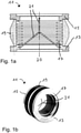
- FIGs 1a and 1b show a damping body 11 according to the prior art.
- the damping body 11 has a pump-side flange 13 for fastening the damping body 11 to a vacuum pump and a recipient-side flange 15 for fastening the damping body 11 to a recipient.
- a corrugated bellows 17 is arranged between the pump-side flange 13 and the recipient-side flange 15 and connects the flanges 13, 15 to one another in a vacuum-tight manner.
- the corrugated bellows 17 is surrounded by a collar 19 made of an elastomer material, which is also arranged between the flange 13, 15 on the pump side and the flange 15 on the recipient side.
- the sleeve 19 rests on the face side of the flanges 13, 15 and thereby limits the contraction of the corrugated bellows 17 caused by the negative pressure in the recipient to a desired extent. Furthermore, since the sleeve 19 is made of elastomeric material, it reduces the transmission of vibrations between the flanges 13, 15 and thus between the vacuum pump and the recipient. It should be noted that the sleeve 19 is also generally dispensed with, for example if the corrugated bellows 17 has a sufficient wall thickness and strength.
- the corrugated bellows 17 there are also two holding brackets 21, one of which is connected to the flange 13 on the pump side and the other to the flange 15 on the recipient side.
- the retaining clips 21 engage in one another in order to prevent impermissible stretching or elongation of the corrugated bellows 17 when the damping body is in a non-evacuated state.
- Such an extension can occur, for example, when the vacuum pump by means of the damping body 11 is suspended from the recipient and thus the entire weight of the vacuum pump acts on the damping body 11 .
- a disadvantage of the damping body 11 according to the prior art is that the retaining brackets 21 are arranged inside the corrugated bellows 17 and thereby reduce the flow conductivity of the damping body 11 or the corrugated bellows 17 .
- the retaining brackets 21 disrupt the flow of the fluid that is conveyed out of the recipient through the damping body 11 by means of the vacuum pump, as shown in FIG Fig. 1b can be seen.
- the damping body 11 does not adequately protect the corrugated bellows 17 in the event of a so-called rotor crash, in which a rotor of the vacuum pump, for example a turbomolecular pump, blocks and, due to the high speed of the vacuum pump, a high torque is suddenly exerted on the pump-side flange 13 of the Damping body 11 and the corrugated bellows 17 acts.
- the bellows 17 is usually made of a thin metal sheet, it cannot withstand such a high torque. This can lead to the corrugated bellows 17 tearing away from the recipient-side flange 15 and thus the vacuum pump from the recipient, so that the vacuum pump can move through the environment in an uncontrolled manner.
- blades can detach from the rotor of the torn-off turbomolecular pump, also move through the environment in an uncontrolled manner and thus pose a further hazard.
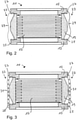
- FIGS 2 and 3 A first and second embodiment of a not claimed damping body 11 are shown, which differs from the damping body 11 described above in that no retaining brackets 21 are arranged inside the corrugated bellows 17, but rather external securing elements 23 between a first fastening position 25 on the pump side Flange 13 and a second fastening position 27 are arranged on the flange 15 on the recipient side.
- the fuse elements 23 in the form of wire ropes 29 are provided instead of wire ropes.
- the wire ropes 29 ( 2 ) and the chains 31 ( 3 ) connect the flange 13 on the pump side and the flange 15 on the recipient side on the outside, ie outside the collar 19 made of elastomeric material, which in turn encloses the corrugated bellows 17 .
- the wire ropes 29 and chains 31 assume the function of the retaining bracket 21, which is why internal retaining brackets 21 can be dispensed with, ie the wire ropes 29 and the chains 31 ensure that the expansion or lengthening of the corrugated bellows 17 is limited when the damping body 11 is not evacuated an allowable level.
- the wire ropes 29 or the chains 31 are not tightly tensioned between the flange 13 on the pump side and the flange 15 on the recipient side. Instead, their length is slightly greater than the mathematical distance between the first and second fastening positions 25, 27. Since the wire ropes 29 are flexible and the individual links of the chains 31 lie loosely on one another when the damping body 11 is in the evacuated state, neither the wire ropes 29 nor the Chains 31 vibrations from the flange 13 on the pump side to the flange 15 on the recipient side.
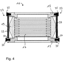
- a third embodiment of a damping body 11 in which the securing elements 23 are formed by stiff flat bars 33 which are each fastened by means of screws 35 to the pump-side flange 13 and to the recipient-side flange 15 .
- the flat bars 33 are fastened without play only on the flange 15 on the recipient side.
- a circumferential gap 37 between the flat bars 33 and the respective screws 35 is provided on the pump-side flange 13 in the evacuated state of the damping body 11 .
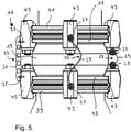
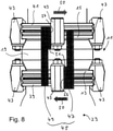
- figure 5 and 7 to 9 each show a side view of further non-claimed embodiments of the damping body 11.
- 6 shows a side view of an embodiment of the damping body 11 according to the invention.
- the damping body 11 is connected on the pump-side flange 13 to a flange 39 of a vacuum pump, not shown, for example a turbomolecular pump, while on the recipient-side flange 15 it is connected to a flange 41 of a recipient, also not shown is.
- the flanges 13 and 39 or the flanges 15 and 41 are connected by means of clamp screws 43.
- a chain 31 is connected to a respective clamping screw 43 on the pump-side or recipient-side flange 13, 15.
- the chain 31 is fastened in a middle section on the outside of the respective clamp screw 43.
- a wire rope 29 is fastened to a respective clamping screw 43 on the pump-side or recipient-side flange 13, 15, similar to that in FIG the in 2 embodiment shown.
- the second and third variants differ in the distance between the fastening positions 25, 27 and accordingly in the length of the wire ropes 29. While in the second variant, similar to the first variant, the wire rope is fastened in the middle section of the respective clamp screw 43 In the third variant, the fastening positions 25, 27 are at the lower or upper edge of the respective clamping screw 43.
- the flange 13 on the pump side and the flange 15 on the recipient side and thus the clamp screws 43 attached to them rotate against each other until the securing elements 23, ie the wire ropes 29 and the chain 31, are tensioned and do not allow any further rotation.
- the securing elements 23 are not taut so that they do not transmit any vibrations from the pump-side flange 13 or from the vacuum pump to the recipient-side flange 15 or to the recipient.
- the securing element 23 is in the form of a wire cable 29 which, according to the invention, extends alternately between a respective first fastening position 25 on the pump-side flange 13 and a second fastening position 27 on the recipient-side flange 15 .
- the wire rope 29 runs, so to speak, in a “zigzag” around the circumference of the damping body 11 .
- the fastening positions 25, 27 are in turn located on the respective clamp screws 43.
- the wire rope 29 Since the wire rope 29 creates a large number of connecting sections between the first and second attachment positions 25, 27, the wire rope 29 can absorb a larger torque in the event of a rotor crash. Consequently, the corrugated bellows 17 or the connection between the vacuum pump and the recipient is even better protected in the event of a rotor crash.
- the securing element 23 comprises a pair 45 of rigid securing elements, which are connected as a first flat bar 47, which is connected to the pump-side flange 13, and as a second flat bar 49, which is connected to the recipient-side flange 15 stands, are trained.
- the first flat bar 47 and the second flat bar 49 are each fastened to a clamp screw 43 which connects the pump-side flange 13 to the flange 39 of the vacuum pump or the recipient-side flange 15 to the flange 41 of the recipient.
- the fastening position 25 of the first flat bar 47 is thus located on a clamping screw 43 which is connected to the pump-side flange 13, while the fastening position 27 of the second flat bar 49 is located on a clamping screw 43 which is connected to the flange 15 on the recipient side.
- the fastening of the securing elements 23 to the clamp screws 43 has the fundamental advantage that existing damping bodies (such as the one shown in Figures 1a and 1b shown damping body 11 according to the prior art) can be retrofitted with securing elements 23, which are each arranged between the clamping screws 43.
- the clamping screws 43 with the securing elements 23 arranged between them represent a cost-effective accessory for retrofitting a damping body 11.
- the flat bars 47, 49 do not touch, so that no vibration transmission can take place between the flange 13 on the pump side and the flange 15 on the recipient side.
- the flange 13 on the pump side and the flange 15 on the recipient side are twisted in relation to one another due to the torque of the vacuum pump, as illustrated by the arrows 50 .
- the rotation of the flanges 13, 15 against one another ends as soon as the first flat iron 47 and the second flat iron 49 touch one another and the torque is thereby transmitted from the pump-side flange 13 to the recipient-side flange 15.
- the sixth embodiment illustrated has in contrast to in 7
- the sixth embodiment illustrated has a first flat bar 47 and a second flat bar 49 with a respective step 51, which is followed by an extended section with a reduced width of the respective flat bar 47, 49. Due to the geometric dimensions of the step 51, in particular due to the spacing of the sections with reduced width, the angle can be specified by which the pump-side flange 13 and the recipient-side Flange 15 can rotate against each other as much as possible until the flat bars 47, 49 touch and prevent further rotation.
- the first flat bar 47 and the second flat bar 49 each have a recess 53, into which a projection 55 of the respective other flat bar 47, 49 engages.
- the flat bars 47, 49 do not touch, so that there is no transmission of vibrations via the flat bars 47, 49.
- the respective recesses 53 and projections 55 of the first and second flat bars 47, 49 come into contact, so that rotation of the pump-side flange 13 relative to the recipient-side flange 15 is limited.
- the recesses 53 together with the projections 55 act as an axial lock, since displacement of the pump-side flange 13 relative to the recipient-side flange 15 in the axial direction, ie in a direction parallel to the central axis 20 of the flanges 13, 15, is limited. Similar to the in Figures 2 to 6 In the illustrated embodiments with wire ropes 29 or chains 31, the additional axial securing limits the maximum expansion or elongation of the corrugated bellows 17 in the event that the damping body is not in the evacuated state and the vacuum pump is suspended from the recipient.
Landscapes
- Engineering & Computer Science (AREA)
- General Engineering & Computer Science (AREA)
- Mechanical Engineering (AREA)
- Non-Positive Displacement Air Blowers (AREA)
- Fluid-Damping Devices (AREA)
- Sealing Devices (AREA)
- Diaphragms And Bellows (AREA)
Priority Applications (2)
| Application Number | Priority Date | Filing Date | Title |
|---|---|---|---|
| EP17187107.2A EP3447298B1 (de) | 2017-08-21 | 2017-08-21 | Dämpfungskörper zur verbindung eine vakuumpumpe |
| JP2018153383A JP6681446B2 (ja) | 2017-08-21 | 2018-08-17 | 緩衝体 |
Applications Claiming Priority (1)
| Application Number | Priority Date | Filing Date | Title |
|---|---|---|---|
| EP17187107.2A EP3447298B1 (de) | 2017-08-21 | 2017-08-21 | Dämpfungskörper zur verbindung eine vakuumpumpe |
Publications (2)
| Publication Number | Publication Date |
|---|---|
| EP3447298A1 EP3447298A1 (de) | 2019-02-27 |
| EP3447298B1 true EP3447298B1 (de) | 2022-02-09 |
Family
ID=59677149
Family Applications (1)
| Application Number | Title | Priority Date | Filing Date |
|---|---|---|---|
| EP17187107.2A Active EP3447298B1 (de) | 2017-08-21 | 2017-08-21 | Dämpfungskörper zur verbindung eine vakuumpumpe |
Country Status (2)
| Country | Link |
|---|---|
| EP (1) | EP3447298B1 (enExample) |
| JP (1) | JP6681446B2 (enExample) |
Families Citing this family (6)
| Publication number | Priority date | Publication date | Assignee | Title |
|---|---|---|---|---|
| TWI834063B (zh) * | 2020-09-30 | 2024-03-01 | 荷蘭商Asml荷蘭公司 | 減輕幫浦故障造成之損害之真空系統 |
| CN112762245A (zh) * | 2021-01-19 | 2021-05-07 | 衡水瑟林科技有限公司 | 一种波纹钢管抗滑移装置 |
| CN114562621A (zh) * | 2022-03-03 | 2022-05-31 | 上海精测半导体技术有限公司 | 一种离子泵隔振装置及其使用方法 |
| CN114791059A (zh) * | 2022-05-27 | 2022-07-26 | 河南中烟工业有限责任公司 | 一种机械连接法兰 |
| CN115978133A (zh) * | 2022-12-26 | 2023-04-18 | 北京中科科仪股份有限公司 | 一种用于电子显微镜的真空减震装置 |
| KR102821857B1 (ko) * | 2023-02-14 | 2025-06-17 | 주식회사 유니온기업 | 디커플러 어셈블리 |
Citations (2)
| Publication number | Priority date | Publication date | Assignee | Title |
|---|---|---|---|---|
| WO2005078288A1 (en) * | 2004-02-06 | 2005-08-25 | The Boc Group Plc | Vibration damper |
| JP2015132373A (ja) * | 2014-01-15 | 2015-07-23 | 株式会社サンケイ技研 | 可撓性管継手およびそれを用いた継手構造 |
Family Cites Families (7)
| Publication number | Priority date | Publication date | Assignee | Title |
|---|---|---|---|---|
| FR2741418B1 (fr) * | 1995-11-21 | 1998-01-16 | Westaflex Automobile | Dispositif de liaison souple de deux conduits rigides |
| DE19745185A1 (de) * | 1997-10-13 | 1999-04-15 | Leybold Ag | Vorrichtung zum vakuumdichten Verbinden von zwei Körpern aus unterschiedlichen Materialien |
| JP2002303294A (ja) * | 2001-04-06 | 2002-10-18 | Boc Edwards Technologies Ltd | 真空ポンプ |
| JP4250353B2 (ja) * | 2001-06-22 | 2009-04-08 | エドワーズ株式会社 | 真空ポンプ |
| JP2004108434A (ja) * | 2002-09-17 | 2004-04-08 | Nikon Corp | ショックアブソーバユニット、ショックアブソーバ及びそれを有する露光装置 |
| JP2005030423A (ja) * | 2003-07-07 | 2005-02-03 | Kazuya Shimizu | 除振装置 |
| JP4925781B2 (ja) * | 2006-10-05 | 2012-05-09 | エドワーズ株式会社 | 真空ポンプとその振動吸収ダンパ |
-
2017
- 2017-08-21 EP EP17187107.2A patent/EP3447298B1/de active Active
-
2018
- 2018-08-17 JP JP2018153383A patent/JP6681446B2/ja active Active
Patent Citations (2)
| Publication number | Priority date | Publication date | Assignee | Title |
|---|---|---|---|---|
| WO2005078288A1 (en) * | 2004-02-06 | 2005-08-25 | The Boc Group Plc | Vibration damper |
| JP2015132373A (ja) * | 2014-01-15 | 2015-07-23 | 株式会社サンケイ技研 | 可撓性管継手およびそれを用いた継手構造 |
Also Published As
| Publication number | Publication date |
|---|---|
| JP2019035409A (ja) | 2019-03-07 |
| EP3447298A1 (de) | 2019-02-27 |
| JP6681446B2 (ja) | 2020-04-15 |
Similar Documents
| Publication | Publication Date | Title |
|---|---|---|
| EP3447298B1 (de) | Dämpfungskörper zur verbindung eine vakuumpumpe | |
| EP2334942B1 (de) | Elastischer gelenkkörper | |
| EP2757299B1 (de) | Rohrklemme | |
| EP2855956B1 (de) | Drehmomentübertragungsvorrichtung | |
| DE102007038493B4 (de) | Elastomeres Buchsenlager mit hydraulischer Dämpfung | |
| DE102011086526B4 (de) | Drehschwingungstilgervorrichtung und Drehmomentübertragungsvorrichtung für ein Kraftfahrzeug | |
| WO2015014359A1 (de) | Fliehkraftpendel | |
| DE102009050346B4 (de) | Kupplungsausrücksystem mit Verdrehsicherung für Nehmerzylinderkolben | |
| DE102010030178A1 (de) | Rotationskupplung und damit versehene Antriebsanordnung | |
| DE102014016829A1 (de) | Elastischer Gelenkkörper | |
| DE102018100234B3 (de) | Drosselvorrichtung mit einstellbarem Blendenelement; Betätigungseinrichtung sowie Kupplung | |
| EP3313712B1 (de) | Axialkugelgelenk | |
| EP3111106B1 (de) | Fliehkraftpendel | |
| DE102017209004B4 (de) | Gleichlaufgelenk in Faserverbundbauweise | |
| DE102016213187B4 (de) | Kupplungseinrichtung | |
| DE102014118700A1 (de) | Vorrichtung zur Übertragung eines Drehmomentes von einem Verbrennungsmotor zu einem Nebenaggregat | |
| DE102018218858B3 (de) | Doppelkupplungsanordnung für einen Kraftfahrzeugantriebsstrang | |
| EP3218620B1 (de) | Hydrobuchse sowie fahrzeug mit derartiger hydrobuchse | |
| WO2020193589A1 (de) | Verriegelungseinrichtung für ein klappenelement, verriegelungsanordnung und kraftfahrzeug | |
| WO2015165455A1 (de) | Fliehkraftpendel | |
| DE102013210723A1 (de) | Sicherungsmutter | |
| EP2673520B1 (de) | Elastische wellenkupplung und elastomersegment | |
| EP3215410B1 (de) | Anschlagdämpfer | |
| DE102005040521B4 (de) | Schienenfahrzeugrad | |
| DE102010010712B4 (de) | Halter zur Montage von Anbauteilen am Gehäuse eines Triebwerks, insbesondere eines Strahltriebwerks |
Legal Events
| Date | Code | Title | Description |
|---|---|---|---|
| PUAI | Public reference made under article 153(3) epc to a published international application that has entered the european phase |
Free format text: ORIGINAL CODE: 0009012 |
|
| STAA | Information on the status of an ep patent application or granted ep patent |
Free format text: STATUS: THE APPLICATION HAS BEEN PUBLISHED |
|
| AK | Designated contracting states |
Kind code of ref document: A1 Designated state(s): AL AT BE BG CH CY CZ DE DK EE ES FI FR GB GR HR HU IE IS IT LI LT LU LV MC MK MT NL NO PL PT RO RS SE SI SK SM TR |
|
| AX | Request for extension of the european patent |
Extension state: BA ME |
|
| STAA | Information on the status of an ep patent application or granted ep patent |
Free format text: STATUS: REQUEST FOR EXAMINATION WAS MADE |
|
| 17P | Request for examination filed |
Effective date: 20190812 |
|
| RBV | Designated contracting states (corrected) |
Designated state(s): AL AT BE BG CH CY CZ DE DK EE ES FI FR GB GR HR HU IE IS IT LI LT LU LV MC MK MT NL NO PL PT RO RS SE SI SK SM TR |
|
| GRAP | Despatch of communication of intention to grant a patent |
Free format text: ORIGINAL CODE: EPIDOSNIGR1 |
|
| STAA | Information on the status of an ep patent application or granted ep patent |
Free format text: STATUS: GRANT OF PATENT IS INTENDED |
|
| INTG | Intention to grant announced |
Effective date: 20211029 |
|
| RIC1 | Information provided on ipc code assigned before grant |
Ipc: F04D 29/64 20060101ALN20211018BHEP Ipc: F16L 27/111 20060101ALI20211018BHEP Ipc: F04D 29/66 20060101ALI20211018BHEP Ipc: F04D 19/04 20060101AFI20211018BHEP |
|
| GRAS | Grant fee paid |
Free format text: ORIGINAL CODE: EPIDOSNIGR3 |
|
| GRAA | (expected) grant |
Free format text: ORIGINAL CODE: 0009210 |
|
| STAA | Information on the status of an ep patent application or granted ep patent |
Free format text: STATUS: THE PATENT HAS BEEN GRANTED |
|
| AK | Designated contracting states |
Kind code of ref document: B1 Designated state(s): AL AT BE BG CH CY CZ DE DK EE ES FI FR GB GR HR HU IE IS IT LI LT LU LV MC MK MT NL NO PL PT RO RS SE SI SK SM TR |
|
| REG | Reference to a national code |
Ref country code: GB Ref legal event code: FG4D Free format text: NOT ENGLISH |
|
| REG | Reference to a national code |
Ref country code: CH Ref legal event code: EP Ref country code: AT Ref legal event code: REF Ref document number: 1467671 Country of ref document: AT Kind code of ref document: T Effective date: 20220215 |
|
| REG | Reference to a national code |
Ref country code: IE Ref legal event code: FG4D Free format text: LANGUAGE OF EP DOCUMENT: GERMAN |
|
| REG | Reference to a national code |
Ref country code: DE Ref legal event code: R096 Ref document number: 502017012563 Country of ref document: DE |
|
| REG | Reference to a national code |
Ref country code: LT Ref legal event code: MG9D |
|
| REG | Reference to a national code |
Ref country code: NL Ref legal event code: MP Effective date: 20220209 |
|
| PG25 | Lapsed in a contracting state [announced via postgrant information from national office to epo] |
Ref country code: SE Free format text: LAPSE BECAUSE OF FAILURE TO SUBMIT A TRANSLATION OF THE DESCRIPTION OR TO PAY THE FEE WITHIN THE PRESCRIBED TIME-LIMIT Effective date: 20220209 Ref country code: RS Free format text: LAPSE BECAUSE OF FAILURE TO SUBMIT A TRANSLATION OF THE DESCRIPTION OR TO PAY THE FEE WITHIN THE PRESCRIBED TIME-LIMIT Effective date: 20220209 Ref country code: PT Free format text: LAPSE BECAUSE OF FAILURE TO SUBMIT A TRANSLATION OF THE DESCRIPTION OR TO PAY THE FEE WITHIN THE PRESCRIBED TIME-LIMIT Effective date: 20220609 Ref country code: NO Free format text: LAPSE BECAUSE OF FAILURE TO SUBMIT A TRANSLATION OF THE DESCRIPTION OR TO PAY THE FEE WITHIN THE PRESCRIBED TIME-LIMIT Effective date: 20220509 Ref country code: NL Free format text: LAPSE BECAUSE OF FAILURE TO SUBMIT A TRANSLATION OF THE DESCRIPTION OR TO PAY THE FEE WITHIN THE PRESCRIBED TIME-LIMIT Effective date: 20220209 Ref country code: LT Free format text: LAPSE BECAUSE OF FAILURE TO SUBMIT A TRANSLATION OF THE DESCRIPTION OR TO PAY THE FEE WITHIN THE PRESCRIBED TIME-LIMIT Effective date: 20220209 Ref country code: HR Free format text: LAPSE BECAUSE OF FAILURE TO SUBMIT A TRANSLATION OF THE DESCRIPTION OR TO PAY THE FEE WITHIN THE PRESCRIBED TIME-LIMIT Effective date: 20220209 Ref country code: ES Free format text: LAPSE BECAUSE OF FAILURE TO SUBMIT A TRANSLATION OF THE DESCRIPTION OR TO PAY THE FEE WITHIN THE PRESCRIBED TIME-LIMIT Effective date: 20220209 Ref country code: BG Free format text: LAPSE BECAUSE OF FAILURE TO SUBMIT A TRANSLATION OF THE DESCRIPTION OR TO PAY THE FEE WITHIN THE PRESCRIBED TIME-LIMIT Effective date: 20220509 |
|
| PG25 | Lapsed in a contracting state [announced via postgrant information from national office to epo] |
Ref country code: PL Free format text: LAPSE BECAUSE OF FAILURE TO SUBMIT A TRANSLATION OF THE DESCRIPTION OR TO PAY THE FEE WITHIN THE PRESCRIBED TIME-LIMIT Effective date: 20220209 Ref country code: LV Free format text: LAPSE BECAUSE OF FAILURE TO SUBMIT A TRANSLATION OF THE DESCRIPTION OR TO PAY THE FEE WITHIN THE PRESCRIBED TIME-LIMIT Effective date: 20220209 Ref country code: GR Free format text: LAPSE BECAUSE OF FAILURE TO SUBMIT A TRANSLATION OF THE DESCRIPTION OR TO PAY THE FEE WITHIN THE PRESCRIBED TIME-LIMIT Effective date: 20220510 Ref country code: FI Free format text: LAPSE BECAUSE OF FAILURE TO SUBMIT A TRANSLATION OF THE DESCRIPTION OR TO PAY THE FEE WITHIN THE PRESCRIBED TIME-LIMIT Effective date: 20220209 |
|
| PG25 | Lapsed in a contracting state [announced via postgrant information from national office to epo] |
Ref country code: IS Free format text: LAPSE BECAUSE OF FAILURE TO SUBMIT A TRANSLATION OF THE DESCRIPTION OR TO PAY THE FEE WITHIN THE PRESCRIBED TIME-LIMIT Effective date: 20220609 |
|
| PG25 | Lapsed in a contracting state [announced via postgrant information from national office to epo] |
Ref country code: SM Free format text: LAPSE BECAUSE OF FAILURE TO SUBMIT A TRANSLATION OF THE DESCRIPTION OR TO PAY THE FEE WITHIN THE PRESCRIBED TIME-LIMIT Effective date: 20220209 Ref country code: SK Free format text: LAPSE BECAUSE OF FAILURE TO SUBMIT A TRANSLATION OF THE DESCRIPTION OR TO PAY THE FEE WITHIN THE PRESCRIBED TIME-LIMIT Effective date: 20220209 Ref country code: RO Free format text: LAPSE BECAUSE OF FAILURE TO SUBMIT A TRANSLATION OF THE DESCRIPTION OR TO PAY THE FEE WITHIN THE PRESCRIBED TIME-LIMIT Effective date: 20220209 Ref country code: EE Free format text: LAPSE BECAUSE OF FAILURE TO SUBMIT A TRANSLATION OF THE DESCRIPTION OR TO PAY THE FEE WITHIN THE PRESCRIBED TIME-LIMIT Effective date: 20220209 Ref country code: DK Free format text: LAPSE BECAUSE OF FAILURE TO SUBMIT A TRANSLATION OF THE DESCRIPTION OR TO PAY THE FEE WITHIN THE PRESCRIBED TIME-LIMIT Effective date: 20220209 |
|
| REG | Reference to a national code |
Ref country code: DE Ref legal event code: R097 Ref document number: 502017012563 Country of ref document: DE |
|
| PG25 | Lapsed in a contracting state [announced via postgrant information from national office to epo] |
Ref country code: AL Free format text: LAPSE BECAUSE OF FAILURE TO SUBMIT A TRANSLATION OF THE DESCRIPTION OR TO PAY THE FEE WITHIN THE PRESCRIBED TIME-LIMIT Effective date: 20220209 |
|
| PLBE | No opposition filed within time limit |
Free format text: ORIGINAL CODE: 0009261 |
|
| STAA | Information on the status of an ep patent application or granted ep patent |
Free format text: STATUS: NO OPPOSITION FILED WITHIN TIME LIMIT |
|
| 26N | No opposition filed |
Effective date: 20221110 |
|
| PG25 | Lapsed in a contracting state [announced via postgrant information from national office to epo] |
Ref country code: SI Free format text: LAPSE BECAUSE OF FAILURE TO SUBMIT A TRANSLATION OF THE DESCRIPTION OR TO PAY THE FEE WITHIN THE PRESCRIBED TIME-LIMIT Effective date: 20220209 |
|
| PG25 | Lapsed in a contracting state [announced via postgrant information from national office to epo] |
Ref country code: MC Free format text: LAPSE BECAUSE OF FAILURE TO SUBMIT A TRANSLATION OF THE DESCRIPTION OR TO PAY THE FEE WITHIN THE PRESCRIBED TIME-LIMIT Effective date: 20220209 |
|
| REG | Reference to a national code |
Ref country code: CH Ref legal event code: PL |
|
| PG25 | Lapsed in a contracting state [announced via postgrant information from national office to epo] |
Ref country code: LU Free format text: LAPSE BECAUSE OF NON-PAYMENT OF DUE FEES Effective date: 20220821 Ref country code: LI Free format text: LAPSE BECAUSE OF NON-PAYMENT OF DUE FEES Effective date: 20220831 Ref country code: CH Free format text: LAPSE BECAUSE OF NON-PAYMENT OF DUE FEES Effective date: 20220831 |
|
| REG | Reference to a national code |
Ref country code: BE Ref legal event code: MM Effective date: 20220831 |
|
| PG25 | Lapsed in a contracting state [announced via postgrant information from national office to epo] |
Ref country code: IE Free format text: LAPSE BECAUSE OF NON-PAYMENT OF DUE FEES Effective date: 20220821 Ref country code: FR Free format text: LAPSE BECAUSE OF NON-PAYMENT OF DUE FEES Effective date: 20220831 |
|
| PG25 | Lapsed in a contracting state [announced via postgrant information from national office to epo] |
Ref country code: BE Free format text: LAPSE BECAUSE OF NON-PAYMENT OF DUE FEES Effective date: 20220831 |
|
| REG | Reference to a national code |
Ref country code: AT Ref legal event code: MM01 Ref document number: 1467671 Country of ref document: AT Kind code of ref document: T Effective date: 20220821 |
|
| PG25 | Lapsed in a contracting state [announced via postgrant information from national office to epo] |
Ref country code: AT Free format text: LAPSE BECAUSE OF NON-PAYMENT OF DUE FEES Effective date: 20220821 |
|
| PG25 | Lapsed in a contracting state [announced via postgrant information from national office to epo] |
Ref country code: HU Free format text: LAPSE BECAUSE OF FAILURE TO SUBMIT A TRANSLATION OF THE DESCRIPTION OR TO PAY THE FEE WITHIN THE PRESCRIBED TIME-LIMIT; INVALID AB INITIO Effective date: 20170821 |
|
| PG25 | Lapsed in a contracting state [announced via postgrant information from national office to epo] |
Ref country code: CY Free format text: LAPSE BECAUSE OF FAILURE TO SUBMIT A TRANSLATION OF THE DESCRIPTION OR TO PAY THE FEE WITHIN THE PRESCRIBED TIME-LIMIT Effective date: 20220209 |
|
| PG25 | Lapsed in a contracting state [announced via postgrant information from national office to epo] |
Ref country code: MK Free format text: LAPSE BECAUSE OF FAILURE TO SUBMIT A TRANSLATION OF THE DESCRIPTION OR TO PAY THE FEE WITHIN THE PRESCRIBED TIME-LIMIT Effective date: 20220209 |
|
| PG25 | Lapsed in a contracting state [announced via postgrant information from national office to epo] |
Ref country code: MT Free format text: LAPSE BECAUSE OF FAILURE TO SUBMIT A TRANSLATION OF THE DESCRIPTION OR TO PAY THE FEE WITHIN THE PRESCRIBED TIME-LIMIT Effective date: 20220209 |
|
| PGFP | Annual fee paid to national office [announced via postgrant information from national office to epo] |
Ref country code: DE Payment date: 20241029 Year of fee payment: 8 |
|
| PGFP | Annual fee paid to national office [announced via postgrant information from national office to epo] |
Ref country code: IT Payment date: 20250825 Year of fee payment: 9 |
|
| PGFP | Annual fee paid to national office [announced via postgrant information from national office to epo] |
Ref country code: GB Payment date: 20250821 Year of fee payment: 9 |
|
| PGFP | Annual fee paid to national office [announced via postgrant information from national office to epo] |
Ref country code: CZ Payment date: 20250808 Year of fee payment: 9 |
|
| PG25 | Lapsed in a contracting state [announced via postgrant information from national office to epo] |
Ref country code: TR Free format text: LAPSE BECAUSE OF FAILURE TO SUBMIT A TRANSLATION OF THE DESCRIPTION OR TO PAY THE FEE WITHIN THE PRESCRIBED TIME-LIMIT Effective date: 20220209 |