EP3447225B1 - Flügelanordnung - Google Patents
Flügelanordnung Download PDFInfo
- Publication number
- EP3447225B1 EP3447225B1 EP17187874.7A EP17187874A EP3447225B1 EP 3447225 B1 EP3447225 B1 EP 3447225B1 EP 17187874 A EP17187874 A EP 17187874A EP 3447225 B1 EP3447225 B1 EP 3447225B1
- Authority
- EP
- European Patent Office
- Prior art keywords
- wing
- sash
- frame
- stop part
- arm
- Prior art date
- Legal status (The legal status is an assumption and is not a legal conclusion. Google has not performed a legal analysis and makes no representation as to the accuracy of the status listed.)
- Active
Links
Images

Classifications
-
- E—FIXED CONSTRUCTIONS
- E05—LOCKS; KEYS; WINDOW OR DOOR FITTINGS; SAFES
- E05D—HINGES OR SUSPENSION DEVICES FOR DOORS, WINDOWS OR WINGS
- E05D15/00—Suspension arrangements for wings
- E05D15/48—Suspension arrangements for wings allowing alternative movements
- E05D15/52—Suspension arrangements for wings allowing alternative movements for opening about a vertical as well as a horizontal axis
- E05D15/5205—Suspension arrangements for wings allowing alternative movements for opening about a vertical as well as a horizontal axis with horizontally-extending checks
Definitions
- the invention relates to a wing arrangement having the features of the preamble of claim 1.
- Such sash arrangements are known from the prior art. With such sash arrangements, the sash can be pivoted or tilted relative to the frame.
- the projection arm couples the sash to the frame.
- a bracket is provided on the projection arm, which is pivotally mounted at one end on the sash and at the other end on the projection arm. In the tilted position, bending moments act on the projection arm due to the force exerted by the bracket.
- the force applied consists of a static component (required holding force) and a dynamic component (“tilting impact").
- the tilting impact describes the force applied when the sash decelerates at the end of the tilting movement. This can lead to damage or destruction of the projection arm.
- EP 1 344 887 A1 , DE 15 84 083 A1 and DE 18 02 164 A1 show devices with features of the preamble of claim 1.
- US 3 994 093 A shows also a device with features of the preamble of claim 1.
- DE 23 02 286 A1 shows a display device in which the sealing system of a window sash can be adjusted by means of a cam.
- the invention is based on the object of reducing the loads acting on the extension arm using simple structural means.
- the invention solves the problem by a sash arrangement having the features of claim 1.
- the sash arrangement is characterized in that a first stop part, which is stationary relative to the sash, is arranged on the extension arm and in that a second stop part, which is stationary relative to the sash, is arranged on the sash, wherein the stop parts are in contact when the sash is closed and/or pivoted (closed and/or rotated position of the sash), so that the sash is aligned or adjusted relative to the extension arm.
- Such a design has the advantage that, in the tilted position of the sash, no or only negligible transverse forces act on the projection arm (scissor arm). This is made possible by the complete omission of a bracket coupling the projection arm to the sash (bracket-less design). As a result, the projection arm is only coupled at one end to the frame and the other end to the sash. Therefore, the projection arm is subject to virtually no bending moment, especially in the tilted position. Due to the comparatively small number of components and their structurally simple design, an overall structurally simple sash arrangement is realized.
- the stop components are used to position or adjust the sash relative to the pivot bearing (e.g., scissor-arm bearing) or relative to the frame in the turned/closed position of the sash.
- the stop components are designed as pins or bolts.
- the wing can be tilted about a first axis, e.g., horizontal in the installed position (tilt axis), and can be rotated or pivoted about a second axis, e.g., vertical in the installed position (rotation axis or pivot axis).
- first axis and the second axis can be oriented orthogonally to each other.
- the sash is mounted on the frame, particularly at the tiltable end, by means of a tilt-and-turn fitting.
- the tilt-and-turn fitting has, in particular, a projection arm (e.g., a scissor arm) and a projection arm bearing for attachment to the frame (e.g., a scissor bearing).
- the projection arm can be guided at one end in a longitudinal slot on the sash and mounted on the frame side, e.g., by means of the projection arm bearing.
- the sash is mounted on the frame, particularly at the end opposite the tiltable end, by means of a corner bearing.
- the corner bearing enables the sash to pivot about the first axis (tilt axis) and the second axis (rotation axis or pivot axis).
- a handle is provided on the sash for operation.
- the handle is used to close and open the sash and to switch between tilting operation (tilt position) and pivoting operation (turning position/closed position).
- tilt position tilt position
- pivoting operation turning position/closed position
- a A locking pin must be provided on the sash-side fitting (e.g. a scissor arm) which corresponds to a locking plate arranged on the extension arm (scissor arm).
- the proposed sash arrangement is particularly suitable for tilt-and-turn windows with exposed or concealed fittings.
- the second stop part can be arranged on a sash-side fitting element.
- This ensures simple and stable alignment of the second stop part on the sash.
- This can be easily mounted on the sash together with the sash-side fitting element.
- the fitting element can, in particular, be a component that overlaps with the projection arm in the turned and/or closed position of the sash, e.g., a faceplate or scissor-type faceplate.
- the first stop part or the second stop part can be designed to be adjustable.
- the orientation of the sash can be adjusted with a simple design.
- the second (sash-side) stop part can be designed to be adjustable, as it is easily accessible for sash adjustment when the sash is tilted.
- the first (extension arm-side) stop part can be designed as a pin, bolt, or hexagon. It is also conceivable for both stop parts to be adjustable. This allows a large adjustment range to be achieved.
- the first stop part or the second stop part can be designed as an eccentric.
- the eccentric can be designed with an engagement or engagement section for a tool.
- the eccentric can have a hexagon socket or hexagon socket. It is also conceivable for both stop parts to be adjustable. This allows for a large adjustment range with a simple and space-saving adjustment option.
- the usual lateral adjustment on the scissor angle (component between the projection arm/scissor arm and the projection arm bearing) can be eliminated because the lateral adjustment of the sash relative to the projection arm bearing is handled by the adjustable stop component (sash-side stop component), particularly the eccentric. This eliminates the need for a separate scissor angle.
- the projection arm/scissor arm and the scissor angle can thus form a single component, particularly a one-piece design. This contributes to a structurally simple, stable, and cost-effective design.
- the sash in the tilted position, can rest with its underside, in particular its lower side relative to the direction of gravity, partially on the frame, in particular on a lower frame section relative to the direction of gravity, preferably at the free end of the sash (opposite the hinge side).
- part of the weight of the sash is absorbed on the opposite side of the hinge.
- the force of the sash acting on the extension arm (scissor arm) proportion of the sash weight) is thus reduced. This promotes a design of the extension arm free from transverse forces.
- the sash rests on the frame in such a way that the sash is not statically overdetermined. This prevents bending loads on the extension arm.
- the sash can rest directly on the frame with its underside. This creates a structurally simpler and more cost-effective sash.
- the sash can have a support element on its underside, particularly one that is designed separately from and/or attached to the sash, by means of which the sash rests on the frame. Resting and any associated wear do not occur directly on the sash, but on the support element. This prevents damage to the sash.
- the support element can be easily adapted to the respective sash arrangement and mounted on the sash, e.g., screwed. This also makes it easy to replace the support element due to wear.
- the frame 12 has an upper frame member 18, a lower frame member 20, and two vertical members 22, 24.
- the sash 14 has a sash frame 26 that defines a sash field 28.
- the sash field 28 can be formed, for example, by glazing.
- the sash frame 18 has an upper profile 30, a lower profile 32 and vertical profiles 34 and 36.
- the projection arm 16 is guided at one end by means of a pin 47 in a longitudinal slot 48 of a sash-side fitting element 50 (scissor stay). At the other end, the projection arm 16 is mounted on the frame 12 by means of the projection arm bearing 46.
- the wing 14 is mounted on the frame 12 by means of a corner bearing 54 (see Figure 1 ).
- the corner bearing 54 enables a pivoting movement of the sash 14 about the first axis 38 (tilt axis) and the second axis 40 (rotation axis or pivot axis).
- a handle 56 is also provided on the sash 14 for operation.
- the handle 56 serves to close and open the sash 14 as well as to convert the sash 14 from tilting to pivoting operation or vice versa.
- the handle 56 cooperates with drive elements, e.g., connecting rods.
- a first stop part 58 which is fixed relative to the extension arm 16 is arranged on the extension arm 16 (see Figure 2 ).
- the first stop part 58 projects from the extension arm 16 in the direction of the sash 14 (in Figure 2 downwards).
- a second stop part 60 is arranged on the sash 14, which is stationary relative to the sash 14. The stop part 60 projects from the sash 14 in the direction of the extension arm 16 (in Figure 2 up).
- the first stop part 58 and the second stop part 60 are in contact with each other in such a way that the first stop part 58 engages behind the second stop part 60 when viewed from the direction of the extension arm bearing 46, so that at least part of the load of the sash 14 is introduced into the frame 12 via the extension arm bearing 46 (see Figure 3 ).
- the second stop part 60 is arranged on a sash-side fitting element, namely on the previously described sash-side fitting element 50.
- the fitting element 50 can be a scissor-type faceplate.
- the first stop part 58 or the second stop part 60 can be adjustable.
- the second stop part 60 is adjustable.
- the first stop part 58 is not adjustable.
- the first stop part 58 or the second stop part 60 can be designed as an eccentric.
- the second stop part 60 is designed as an eccentric.
- the eccentric can be rotated relative to the fitting element 50 for adjustment.
- the first stop part 58 is designed as a pin or bolt.
- a locking pin 62 guided in the sash-side fitting element 50.
- the locking pin 62 is coupled to a drive rod 64 of the sash-side fitting device 66 and can be displaced by the drive rod 64.
- the locking pin 62 engages in a groove 70 of a striker plate 68 attached to the extension arm 16.
- the locking pin 62 can optionally be used as a (further) eccentric be designed to adjust the contact pressure of the sash 14 on the frame 12 (see Figure 4 ).
- the sash assembly 10 is configured such that the sash 14, in the tilted position, rests with its underside (underside of the lower profile 32) partially on the frame 12 (lower frame member 20), specifically at the free end of the sash 14 (opposite the hinge side).
- part of the weight of the sash 14 is absorbed on the opposite side of the hinge (see force F3 at corner C in Figure 1 ).
- a further part of the weight of the sash 14 is absorbed on the hinge side, namely by the corner bearing 54 (see force F1 at corner A in Figure 1 ).
- the wing 14 rests with its underside (underside of the lower profile 32) directly on the frame 14 (lower frame member 20).
- the sash 14 can have a support element on its underside, by means of which the sash 14 rests on the frame 12.
- the frame 12 can optionally have a counter-support element, e.g., a tilting striker plate, by means of which the sash 14 rests on the frame 12, in particular on its lower frame section (lower frame member 20).
- Figure 4 shows a fitting device 65 (sash fitting) which has a sash-side fitting device 66 mounted on the sash 14 (not shown).
- the fitting device 66 has a frame-side fitting device 67 mounted on the frame 12 (not shown).
- the fitting device 65 forms a component of the sash assembly 10. Due to the optimizations described above, the fitting device 65 and thus the sash assembly 10 as a whole are structurally considerably simplified.
Landscapes
- Engineering & Computer Science (AREA)
- Mechanical Engineering (AREA)
- Hinges (AREA)
- Wing Frames And Configurations (AREA)
Description
- Die Erfindung betrifft eine Flügelanordnung mit den Merkmalen des Oberbegriffs von Anspruch 1.
- Derartige Flügelanordnungen sind aus dem Stand der Technik bekannt. Bei solchen Flügelanordnungen kann der Flügel relativ zum Rahmen verschwenkt oder gekippt werden. Der Ausstellarm koppelt den Flügel mit dem Rahmen. Am Ausstellarm ist eine Lasche vorgesehen, die jeweils über einen Drehpunkt einends schwenkbar am Flügel und andernends schwenkbar am Ausstellarm gelagert ist. In Kippstellung wirken durch Krafteinwirkung der Lasche auf den Ausstellarm Biegemomente. Die Krafteinwirkung setzt sich aus einer statischen Komponente (erforderliche Haltekraft) und einer dynamischen Komponente ("Kippschlag") zusammen. Der Kippschlag beschreibt die Krafteinwirkung durch das Abbremsen des Flügels am Ende der Kippbewegung. Dies kann zur Beschädigung oder Zerstörung des Ausstellarms führen. Bei einer aus
DE 75 28 778 U bekannten Ausstellvorrichtung ist der Zusatzarm (Lasche) über ein Langloch mit der Ausstellstange gekoppelt, so dass Biegemomente auf den Ausstellarm reduziert sind.EP 1 344 887 A1 ,DE 15 84 083 A1 undDE 18 02 164 A1 zeigen Vorrichtungen mit Merkmalen des Oberbegriffs von Anspruch 1.US 3 994 093 A zeigt ebenfalls eine Vorrichtung mit Merkmalen des Oberbegriffs von Anspruch 1.DE 23 02 286 A1 zeigt eine Ausstellvorrichtung, bei der mittels Nockens die Dichtungsanlage eines Fensterflügels eingestellt werden kann. - Der Erfindung liegt die Aufgabe zugrunde, mit einfachen konstruktiven Mitteln die auf den Ausstellarm wirkenden Belastungen zu reduzieren.
- Die Erfindung löst die Aufgabe durch eine Flügelanordnung mit den Merkmalen des Anspruchs 1. Danach zeichnet sich die Flügelanordnung dadurch aus, dass an dem Ausstellarm ein relativ zum Ausstellarm ortsfestes erstes Anschlagteil angeordnet ist und dass an dem Flügel ein relativ zum Flügel ortsfestes zweites Anschlagteil angeordnet ist, wobei die Anschlagteile bei geschlossenem und/oder verschwenktem Flügel (Geschlossen- und/oder Drehstellung des Flügels) in Kontakt sind, so dass der Flügel relativ zum Ausstellarm ausgerichtet bzw. justiert ist.
- Eine solche Ausgestaltung hat den Vorteil, dass in der gekippten Stellung des Flügels keine oder nur vernachlässigbar geringe Querkräfte auf den Ausstellarm (Scherenarm) wirken. Dies wird dadurch ermöglicht, dass auf eine den Ausstellarm mit dem Flügel koppelnde Lasche gänzlich verzichtet wird (laschenlose Ausgestaltung). Dadurch ist der Ausstellarm lediglich einends mit dem Rahmen und andernends mit dem Flügel gekoppelt. Daher unterliegt der Ausstellarm insbesondere in Kippstellung praktisch keinem Biegemoment. Aufgrund der vergleichsweise geringen Anzahl an Komponenten und deren konstruktiv einfachen Ausgestaltung ist eine insgesamt konstruktiv einfache Flügelanordnung realisiert. Die Anschlagteile dienen zur Positionierung bzw. Justierung des Flügels relativ zum Schwenklager (bspw. Scherenlager) bzw. relativ zum Rahmen in Drehstellung/Geschlossenstellung des Flügels. Die Anschlagteile sind im einfachsten Fall als Stift oder Bolzen ausgebildet.
- Der Flügel ist insbesondere um eine erste, bspw. in Einbaulage horizontale, Achse kippbar (Kippachse) und um eine zweite, bspw. in Einbaulage vertikale, Achse drehbar oder verschwenkbar (Drehachse oder Schwenkachse). Die erste Achse und die zweite Achse können orthogonal zueinander orientiert sein.
- Der Flügel ist insbesondere am auskippbaren Flügelende mittels eines Drehkippbeschlags an dem Rahmen gelagert. Der Drehkippbeschlag weist insbesondere einen Ausstellarm (bspw. ein Scherenarm) und eine Ausstellarmlagerung zur Befestigung am Rahmen auf (bspw. ein Scherenlager). Der Ausstellarm kann einends in einem flügelseitigen Längsschlitz geführt sein und andernends rahmenseitig gelagert sein, bspw. mittels der Ausstellarmlagerung. Weiter ist der Flügel insbesondere am dem auskippbaren Flügelende gegenüberliegenden Flügelende mittels eines Ecklagers am Rahmen gelagert. Das Ecklager ermöglicht eine Schwenkbewegung des Flügels um die erste Achse (Kippachse) und die zweite Achse (Drehachse oder Schwenkachse).
- Weiter erfindungsgemäß ist am Flügel eine Handhabe zur Betätigung vorgesehen. Die Handhabe dient zum Schließen und Öffnen des Flügels sowie zum Umstellen zwischen Kippbetrieb (Kippstellung) und Schwenkbetrieb (Drehstellung/Geschlossenstellung). Zur Positionierung bzw. Verriegelung des Ausstellarms am Flügel (Verriegelung für Drehstellung/Geschlossenstellung) kann an einem flügelseitigen Beschlagteil (bspw. einem Scherenstulp) ein Schließzapfen vorgesehen sein, der mit einer am Ausstellarm (Scherenarm) angeordneten Schließplatte korrespondiert.
- Die vorgeschlagene Flügelanordnung eignet sich insbesondere für Dreh-Kipp-Fenster mit aufliegenden oder verdeckt liegenden Beschlägen.
- Im Rahmen einer bevorzugten Ausgestaltung kann das zweite Anschlagteil an einem flügelseitigen Beschlagelement angeordnet sein. Hiermit ist eine einfache und stabile Zuordnung des zweiten Anschlagteils am Flügel sichergestellt. Dieses kann auf einfache Weise zusammen mit dem flügelseitigen Beschlagelement am Flügel montiert werden. Bei dem Beschlagelement kann es sich insbesondere um eine Komponente handeln, die in Drehstellung und/oder Geschlossenstellung des Flügels in Überdeckung mit dem Ausstellarm ist, bspw. einem Stulp oder Scherenstulp.
- In zweckmäßiger Weise kann das erste Anschlagteil oder das zweite Anschlagteil einstellbar ausgebildet sein. Auf diese Weise ist die Ausrichtung des Flügels mit einer einfachen Ausgestaltung einstellbar. Bspw. kann das zweite (flügelseitige) Anschlagteil einstellbar ausgebildet sein, da dieses bei gekipptem Flügel zur Flügeljustierung gut zu erreichen ist. Das erste (ausstellarmseitige) Anschlagteil kann als Stift oder Bolzen oder Sechskant (6-Kant) ausgebildet sein. Ebenfalls denkbar ist, dass beide Anschlagteile einstellbar ausgebildet sind. Hiermit kann ein großer Verstellbereich erzielt werden.
- Weiter erfindungsgemäß kann das erste Anschlagteil oder das zweite Anschlagteil als Exzenter ausgebildet sein. Hiermit ist eine konstruktiv einfache und platzsparende Einstellmöglichkeit geschaffen. Am Exzenter kann ein Angriffs- oder Eingriffsabschnitt für ein Werkzeug ausgebildet sein. Bspw. kann der Exzenter einen Innensechskant oder Außensechskant aufweisen. Ebenfalls denkbar ist, dass beide Anschlagteile einstellbar ausgebildet sind. Hiermit kann bei einer konstruktiv einfachen und platzsparenden Einstellmöglichkeit ein großer Verstellbereich erzielt werden.
- Die übliche Seitenverstellung am Scherenwinkel (Komponente zwischen Ausstellarm/Scherenarm und Ausstellarmlagerung) kann entfallen, weil die Seitenverstellung des Flügels relativ zur Ausstellarmlagerung von dem einstellbaren Anschlagteil (flügelseitiges Anschlagteil), insbesondere von dem Exzenter, übernommen wird. Damit kann ein gesonderter Scherenwinkel entfallen. Ausstellarm/Scherenarm und Scherenwinkel können somit ein einziges Bauteil bilden, insbesondere einstückig ausgebildet sein. Dies trägt zur einer konstruktiv einfachen, stabilen und kostengünstigen Ausgestaltung bei.
- Im Rahmen einer bevorzugten Ausgestaltung kann der Flügel in Kippstellung mit seiner Unterseite, insbesondere seiner bezogen auf die Schwerkraftrichtung unteren Seite, abschnittsweise auf dem Rahmen, insbesondere einem bezogen auf die Schwerkraftrichtung unteren Rahmenabschnitt, aufliegen, vorzugsweise am freien Ende des Flügels (Bandgegenseite). Dadurch wird in Kippstellung ein Teil der Gewichtskraft des Flügels an der Bandgegenseite aufgenommen. Die auf den Ausstellarm (Scherenarm) wirkende Kraft des Flügels (Anteil des Flügelgewichts) ist somit reduziert. Dies begünstigt eine querkraftfreie Ausgestaltung des Ausstellarms. Der Flügel liegt insbesondere derart auf dem Rahmen auf, dass der Flügel statisch nicht überbestimmt ist. Dadurch können Biegebelastungen auf den Ausstellarm vermieden werden.
- Im Konkreten kann der Flügel mit seiner Unterseite unmittelbar auf dem Rahmen aufliegen. Hiermit ist konstruktiv einfacher und kostengünstiger Flügel geschaffen.
- Alternativ hierzu kann der Flügel an seiner Unterseite ein, insbesondere separat zum Flügel ausgebildetes und/oder am Flügel befestigtes, Auflageelement aufweisen, mittels dem der Flügel auf dem Rahmen aufliegt. Ein Aufliegen und damit ggf. einhergehender Verschleiß findet nicht unmittelbar am Flügel, sondern am Auflageelement statt. Dadurch können Verletzungen des Flügels vermieden werden. Das Auflageelement kann auf einfache Weise an die jeweilige Flügelanordnung angepasst und am Flügel montiert werden, bspw. verschraubt werden. Auch ein verschleißbedingter Austausch des Auflageelements ist somit auf einfache Weise möglich.
- Alternativ oder ergänzend kann der Rahmen, insbesondere an seinem unteren Rahmenabschnitt, ein Gegenauflageelement (bspw. eine Kippschließplatte) aufweisen, mittels dem der Flügel auf dem Rahmen aufliegt. Ein Aufliegen und damit ggf. einhergehender Verschleiß findet nicht unmittelbar am Rahmen, sondern am Gegenauflageelement statt. Dadurch können Verletzungen des Rahmens vermieden werden. Das Gegenauflageelement kann an die jeweilige Flügelanordnung angepasst und am Rahmen montiert, bspw. verschraubt werden. Ein verschleißbedingter Austausch des Gegenauflageelements ist auf einfache Weise möglich.
- Die Erfindung wird im Folgenden anhand der Figuren näher erläutert, wobei gleiche oder funktionale Elemente ggf. lediglich einmal mit Bezugszeichen versehen sind. Es zeigen:
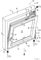
- Figur 1
- eine Ausführungsform einer Flügelanordnung in mit Flügel in gekippter Stellung in einer perspektivischen Ansicht;
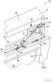
- Figur 2
- einen vergrößerten Ausschnitt der Flügelanordnung aus
Figur 1 mit Flügel in gekippter Stellung; - Figur 3
- die Flügelanordnung aus
Figur 1 mit Flügel in geschlossener Stellung in einer teilweise geschnittenen Ansicht; und - Figur 4
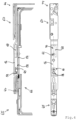
- einen Beschlag der Flügelanordnung aus
Figur 1 in einer teilweisen Seitenansicht und einer Draufsicht. -
Figur 1 zeigt eine Flügelanordnung, die insgesamt mit dem Bezugszeichen 10 bezeichnet ist. Die Flügelanordnung 10 weist einen ortsfesten Rahmen 12 und einen am Rahmen 12 gelagerten Flügel 14 eines Fensters oder einer Tür auf. Der Flügel 14 ist relativ zum Rahmen 12 kippbar und verschwenkbar. Weiter ist der Flügel 14 mittels eines Ausstellarms 16 mit dem Rahmen 12 gekoppelt, bspw. mittels eines Scherenarms. - Der Rahmen 12 weist einen oberen Rahmenholm 18, einen unteren Rahmenholm 20 und zwei Vertikalholme 22, 24 auf. Der Flügel 14 weist einen Flügelrahmen 26 auf, der ein Flügelfeld 28 begrenzt. Das Flügelfeld 28 kann bspw. durch eine Verglasung gebildet sein. Der Flügelrahmen 18 weist ein oberes Profil 30, ein unteres Profil 32 sowie Vertikalprofile 34 und 36 auf.
- Die Schwerkraftrichtung G weist in
Figur 1 nach unten. Der Flügel 14 ist um eine erste Achse 38 relativ zum Rahmen 12 kippbar (Kippachse). Zudem ist der Flügel 14 in nicht gekipptem Zustand (Drehstellung oder Schwenkstellung) um eine zweite Achse 40 (Drehachse oder Schwenkachse) relativ zum Rahmen 12 drehbar bzw. verschwenkbar. Der Flügel 14 ist am auskippbaren Flügelende 42 mittels eines Drehkippbeschlags 44 am Rahmen 12 gelagert. Der Drehkippbeschlag 44 weist den Ausstellarm 16 (Scherenarm) und eine Ausstellarmlagerung 46 (Scherenlager) zur Befestigung am Rahmen 12 auf (sieheFigur 2 ). Der Ausstellarm 16 ist einends mittels eines Zapfens 47 in einem Längsschlitz 48 eines flügelseitigen Beschlagelements 50 (Scherenstulp) geführt. Andernends ist der Ausstellarm 16 mittels der Ausstellarmlagerung 46 am Rahmen 12 gelagert. - Am dem auskippbaren Flügelende 42 gegenüberliegenden Flügelende 52 ist der Flügel 14 mittels eines Ecklagers 54 am Rahmen 12 gelagert (siehe
Figur 1 ). Das Ecklager 54 ermöglicht eine Schwenkbewegung des Flügels 14 um die erste Achse 38 (Kippachse) und die zweite Achse 40 (Drehachse oder Schwenkachse). - Am Flügel 14 ist weiter eine Handhabe 56 zur Betätigung vorgesehen. Die Handhabe 56 dient zum Schließen und Öffnen des Flügels 14 sowie zum Umstellen des Flügels 14 von Kippbetrieb auf Schwenkbetrieb bzw. umgekehrt. Dabei wirkt die Handhabe 56 mittels Treibelementen, bspw. Treibstangen, zusammen.
- An dem Ausstellarm 16 ist ein relativ zum Ausstellarm 16 ortsfestes erstes Anschlagteil 58 angeordnet (siehe
Figur 2 ). Das erste Anschlagteil 58 ragt vom Ausstellarm 16 in Richtung des Flügels 14 ab (inFigur 2 nach unten). An dem Flügel 14 ist ein relativ zum Flügel 14 ortsfestes zweites Anschlagteil 60 angeordnet. Das Anschlagteil 60 ragt in Richtung des Ausstellarms 16 vom Flügel 14 ab (inFigur 2 nach oben). - Die Anschlagteile 58, 60 sind bei geschlossenem und/oder verschwenktem Flügel 14 in Kontakt, wodurch der Flügel 14 relativ zum Ausstellarm 16 ausgerichtet bzw. justiert ist. Der Ausstellarm 16 und das flügelseitige Beschlagelement 50 sind dann nahezu parallel zueinander und in Überdeckung miteinander (siehe
Figur 3 und4 ). "Nahezu parallel zueinander" schließt Abweichungen von ±5° von der parallelen Orientierung mit ein. - Insbesondere sind bei geschlossenem und/oder verschwenktem Flügel 14 das erste Anschlagteil 58 und das zweite Anschlagteil 60 derart miteinander in Kontakt, dass das erste Anschlagteil 58 das zweite Anschlagteil 60 aus Blickrichtung der Ausstellarmlagerung 46 hintergreift, so dass zumindest ein Teil der Last des Flügels 14 über die Ausstellarmlagerung 46 in den Rahmen 12 eingeleitet wird (siehe
Figur 3 ). - In der gekippten Stellung des Flügels 14 sind das erste Anschlagteil 58 und das zweite Anschlagteil 60 nicht miteinander in Kontakt (siehe
Figur 2 ). Dadurch wirkt auf den Ausstellarm 16 keine oder nur eine vernachlässigbar geringe Querkraft. Dadurch sind die auf den Ausstellarm 16 wirkenden Kräfte reduziert (siehe Pfeil F2 an Ecke B inFigur 1 ) - Das zweite Anschlagteil 60 ist an einem flügelseitigen Beschlagelement angeordnet, und zwar an dem zuvor bereits beschriebenen flügelseitigen Beschlagelement 50. Bei dem Beschlagelement 50 kann es sich um einen Scherenstulp handeln.
- Das erste Anschlagteil 58 oder das zweite Anschlagteil 60 können einstellbar ausgebildet sein. Im vorliegenden Ausführungsbeispiel ist das zweite Anschlagteil 60 einstellbar ausgebildet. Das erste Anschlagteil 58 ist nicht einstellbar ausgeführt.
- Das erste Anschlagteil 58 oder das zweite Anschlagteil 60 können als Exzenter ausgebildet sein. Im vorliegenden Ausführungsbeispiel ist das zweite Anschlagteil 60 als Exzenter ausgebildet. Der Exzenter kann zur Einstellung relativ zum Beschlagelement 50 gedreht werden. Das erste Anschlagteil 58 ist als Stift oder Bolzen ausgeführt. Je weiter die Kontur des als Exzenter ausgebildeten zweiten Anschlagteils 60 in Richtung des ersten Anschlagteils 58 ragt, desto mehr wird das flügelseitige Beschlagelement 50 und damit der Flügel 14 insgesamt in Richtung an den (rechten) Vertikalholm 24 herangeholt (siehe
Figur 3 und4 ). - Eine weitere Positionierung bzw. Verriegelung des Flügels 14 erfolgt durch einen im flügelseitigen Beschlagelement 50 geführten Schließzapfen 62. Der Schließzapfen 62 ist mit einer Treibstange 64 der flügelseitigen Beschlageinrichtung 66 gekoppelt und kann durch die Treibstange 64 verlagert werden. Der Schließzapfen 62 greift in eine Nut 70 einer am Ausstellarm 16 befestigten Schließplatte 68 ein. Der Schließzapfen 62 kann optional als (weiterer) Exzenter ausgebildet sein, um den Anpressdruck des Flügels 14 auf den Rahmen 12 einstellen zu können (siehe
Figur 4 ). - Die Flügelanordnung 10 ist derart eingerichtet, dass der Flügel 14 in der gekippten Stellung mit seiner Unterseite (Unterseite des unteren Profils 32) abschnittsweise auf dem Rahmen 12 (unterer Rahmenholm 20) aufliegt, und zwar am freien Ende des Flügels 14 (Bandgegenseite). Hierdurch wird in der gekippten Stellung ein Teil der Gewichtskraft des Flügels 14 an der Bandgegenseite aufgenommen (siehe Kraft F3 an Ecke C in
Figur 1 ). Ein weiterer Teil der Gewichtskraft des Flügels 14 wird an der Bandseite aufgenommen, und zwar durch das Ecklager 54 (siehe Kraft F1 an Ecke A inFigur 1 ). - Im vorliegenden Ausführungsbeispiel liegt der Flügel 14 mit seiner Unterseite (Unterseite des unteren Profils 32) unmittelbar auf dem Rahmen 14 (unterer Rahmenholm 20) auf.
- Optional kann der Flügel 14 an seiner Unterseite ein Auflageelement aufweisen, mittels dem der Flügel 14 auf dem Rahmen 12 aufliegt. Unabhängig davon kann optional der Rahmen 12, insbesondere an seinem unteren Rahmenabschnitt (unterer Rahmenholm 20), ein Gegenauflageelement, bspw. eine Kippschließplatte aufweisen, mittels dem der Flügel 14 auf dem Rahmen 12 aufliegt.
-
Figur 4 zeigt eine Beschlageinrichtung 65 (Flügelbeschlag) die eine flügelseitige Beschlageinrichtung 66 aufweist, die am Flügel 14 montiert ist (nicht dargestellt). Zudem weist die Beschlageinrichtung 66 eine rahmenseitige Beschlageinrichtung 67 auf, die am Rahmen 12 montiert ist (nicht dargestellt). - Die Beschlageinrichtung 65 bildet eine Komponente der Flügelanordnung 10. Durch die voranstehend beschriebenen Optimierungen sind die Beschlageinrichtung 65 und damit die Flügelanordnung 10 insgesamt konstruktiv erheblich vereinfacht.
Claims (7)
- Flügelanordnung (10) mit einem ortsfesten Rahmen (12) und einem am Rahmen (12) gelagerten Flügel (14) eines Fensters oder einer Tür, wobei der Flügel (14) relativ zum Rahmen (12) kippbar und verschwenkbar ist, und wobei der Flügel (14) mittels eines Ausstellarms (16) mit dem Rahmen (12) gekoppelt ist, wobei zur Betätigung am Flügel (14) eine Handhabe (56) zum Schließen und Öffnen des Flügels (14) sowie zum Umstellen zwischen Kippbetrieb und Schwenkbetrieb vorgesehen ist, wobei die Handhabe (56) hierzu mit Treibstangen zusammenwirkt, wobei an dem Ausstellarm (16) ein relativ zum Ausstellarm (16) ortsfestes erstes Anschlagteil (58) angeordnet ist und wobei an dem Flügel (14) ein relativ zum Flügel (14) ortsfestes zweites Anschlagteil (60) angeordnet ist, wobei die Anschlagteile (58, 60) als Stift, Bolzen oder Exzenter ausgebildet und bei geschlossenem und/oder verschwenktem Flügel (14) in Kontakt sind, so dass der Flügel (14) relativ zum Ausstellarm (16) ausgerichtet ist, wobei der Ausstellarm (16) laschenlos ausgebildet ist, so dass der Ausstellarm (16) lediglich einends mit dem Rahmen (12) und andernends mit dem Flügel (14) gekoppelt ist.
- Flügelanordnung (10) nach Anspruch 1, dadurch gekennzeichnet, dass das zweite Anschlagteil (60) an einem flügelseitigen Beschlagelement (50) angeordnet ist.
- Flügelanordnung (10) nach Anspruch 1 oder 2, dadurch gekennzeichnet, dass das erste Anschlagteil (58) oder das zweite Anschlagteil (60) einstellbar ausgebildet ist.
- Flügelanordnung (10) nach einem der voranstehenden Ansprüche, dadurch gekennzeichnet, dass der Flügel (14) in Kippstellung mit seiner Unterseite abschnittsweise auf dem Rahmen (12) aufliegt, insbesondere am freien Ende des Flügels (14).
- Flügelanordnung (10) nach Anspruch 4, dadurch gekennzeichnet, dass der Flügel (14) mit seiner Unterseite unmittelbar auf dem Rahmen (12) aufliegt.
- Flügelanordnung (10) nach Anspruch 4, dadurch gekennzeichnet, dass der Flügel (14) an seiner Unterseite ein Auflageelement aufweist, mittels dem der Flügel (14) auf dem Rahmen (12) aufliegt.
- Flügelanordnung (10) nach einem der Ansprüche 4 bis 6, dadurch gekennzeichnet, dass der Rahmen (12), insbesondere an seinem unteren Rahmenabschnitt, ein Gegenauflageelement aufweist, mittels dem der Flügel (14) auf dem Rahmen (12) aufliegt.
Priority Applications (2)
| Application Number | Priority Date | Filing Date | Title |
|---|---|---|---|
| ES17187874T ES3035313T3 (en) | 2017-08-25 | 2017-08-25 | Wing assembly |
| EP17187874.7A EP3447225B1 (de) | 2017-08-25 | 2017-08-25 | Flügelanordnung |
Applications Claiming Priority (1)
| Application Number | Priority Date | Filing Date | Title |
|---|---|---|---|
| EP17187874.7A EP3447225B1 (de) | 2017-08-25 | 2017-08-25 | Flügelanordnung |
Publications (2)
| Publication Number | Publication Date |
|---|---|
| EP3447225A1 EP3447225A1 (de) | 2019-02-27 |
| EP3447225B1 true EP3447225B1 (de) | 2025-06-18 |
Family
ID=59702595
Family Applications (1)
| Application Number | Title | Priority Date | Filing Date |
|---|---|---|---|
| EP17187874.7A Active EP3447225B1 (de) | 2017-08-25 | 2017-08-25 | Flügelanordnung |
Country Status (2)
| Country | Link |
|---|---|
| EP (1) | EP3447225B1 (de) |
| ES (1) | ES3035313T3 (de) |
Citations (1)
| Publication number | Priority date | Publication date | Assignee | Title |
|---|---|---|---|---|
| US3994093A (en) * | 1974-05-30 | 1976-11-30 | Aug. Winkhaus | Window with sash capable of pivoting movement about two perpendicular axes |
Family Cites Families (5)
| Publication number | Priority date | Publication date | Assignee | Title |
|---|---|---|---|---|
| DE1584083A1 (de) * | 1966-02-19 | 1970-01-08 | Frank Gmbh Wilh | Sicherungsvorrichtung fuer Schwenk-Kippfluegel von Fenstern,Tueren od. dgl. |
| DE1802164A1 (de) * | 1968-10-09 | 1970-04-16 | Frank Gmbh Wilh | Beschlag fuer einen Fluegel eines Fensters,einer Tuer od.dgl.,dessen Fluegel sowohl schwenkbar als auch kippbar gelagert ist |
| DE7528778U (de) | 1970-08-05 | 1977-02-17 | Fa. Aug. Winkhaus, 4404 Telgte | Ausstellvorrichtung fuer wahlweise kippbare und schwenkbare fluegel von fenstern oder dergleichen |
| DE2302286B2 (de) * | 1973-01-18 | 1982-02-04 | Siegenia-Frank Kg, 5900 Siegen | Verstellbare Ausstellvorrichtung für Drehkipflügel von Fenstern, Türen od. dgl. |
| DE20204115U1 (de) * | 2002-03-14 | 2002-10-17 | Alfred Bohn GmbH & Co. KG, 74889 Sinsheim | Dreh-Kipp-Beschlag für Fenster- o.dgl. -Flügel, insbesondere Kellerfenster und Fenster mit einem solchen Beschlag |
-
2017
- 2017-08-25 ES ES17187874T patent/ES3035313T3/es active Active
- 2017-08-25 EP EP17187874.7A patent/EP3447225B1/de active Active
Patent Citations (1)
| Publication number | Priority date | Publication date | Assignee | Title |
|---|---|---|---|---|
| US3994093A (en) * | 1974-05-30 | 1976-11-30 | Aug. Winkhaus | Window with sash capable of pivoting movement about two perpendicular axes |
Also Published As
| Publication number | Publication date |
|---|---|
| EP3447225A1 (de) | 2019-02-27 |
| ES3035313T3 (en) | 2025-09-01 |
Similar Documents
| Publication | Publication Date | Title |
|---|---|---|
| EP2828460B1 (de) | Beschlag für einen parallel abstellbaren und in dieser parallelabstelllage horizontal verschiebbaren flügel von fenstern oder türen | |
| DE4117407C2 (de) | Drehkippbeschlag | |
| DE3738596A1 (de) | Verdeckt im falz angeordneter beschlag fuer schwenklager, insb. kipp-schwenklager, fuer fluegel von fenstern, tueren oder dgl. | |
| EP1837472B1 (de) | Fenster, Tür oder dgl. mit einer Flügellastabtrageinrichtung | |
| DE102007054476B4 (de) | Kulissenanordnung | |
| EP0276678B1 (de) | Beschlag für einen wenigstens kippbaren Flügel eines Fensters, einer Tür od. dgl. | |
| EP1017920A1 (de) | Beschlag zur drehlagerung eines fenster- oder türflügels | |
| EP2754815B1 (de) | Kippbeschlag für einen fenster- oder türflügel | |
| CH657659A5 (de) | Drehkippfenster oder drehkipptuer mit einem seitenscharnier und einem ausstellarm. | |
| EP4045745B1 (de) | Ecklager | |
| EP3447225A1 (de) | Flügelanordnung | |
| EP1391576B1 (de) | Verwindungskompensation von abstellbaren Flügeln | |
| EP3278693B1 (de) | Beschlag für eine schiebetüre | |
| EP1118740B1 (de) | Antrieb für einen an einem ortsfesten Rahmen drehbar gelagerten Flügel eines Fenster, einer Tür oder dergleichen | |
| EP0748414B1 (de) | Kipptor | |
| AT411085B (de) | Drehkippbeschlag für ein rundbogenfenster | |
| WO2020260509A1 (de) | Gelenkanordnung und möbelstück | |
| EP1757767B1 (de) | Eckband | |
| EP3204584B1 (de) | Winkelförmiger beschlag | |
| EP4108877B1 (de) | Scharnier für eine türe, ein fenster oder ein ähnliches bauteil | |
| EP0875651A2 (de) | Selbsttätig wirkende Justiervorrichtung | |
| DE8111079U1 (de) | Ecklager fuer fluegel von fenstern, tueren od. dgl. | |
| DE19814929B4 (de) | Hubvorrichtung für eine Sattelkupplung | |
| WO2004063507A1 (de) | Beschlagseinheit für ein fenster oder eine tür | |
| EP2034114B1 (de) | Verdeckt liegende Entlastungsanordnung für ein Fenster, eine Tür oder dergleichen |
Legal Events
| Date | Code | Title | Description |
|---|---|---|---|
| PUAI | Public reference made under article 153(3) epc to a published international application that has entered the european phase |
Free format text: ORIGINAL CODE: 0009012 |
|
| STAA | Information on the status of an ep patent application or granted ep patent |
Free format text: STATUS: REQUEST FOR EXAMINATION WAS MADE |
|
| 17P | Request for examination filed |
Effective date: 20180927 |
|
| AK | Designated contracting states |
Kind code of ref document: A1 Designated state(s): AL AT BE BG CH CY CZ DE DK EE ES FI FR GB GR HR HU IE IS IT LI LT LU LV MC MK MT NL NO PL PT RO RS SE SI SK SM TR |
|
| AX | Request for extension of the european patent |
Extension state: BA ME |
|
| STAA | Information on the status of an ep patent application or granted ep patent |
Free format text: STATUS: EXAMINATION IS IN PROGRESS |
|
| 17Q | First examination report despatched |
Effective date: 20210521 |
|
| GRAP | Despatch of communication of intention to grant a patent |
Free format text: ORIGINAL CODE: EPIDOSNIGR1 |
|
| STAA | Information on the status of an ep patent application or granted ep patent |
Free format text: STATUS: GRANT OF PATENT IS INTENDED |
|
| INTG | Intention to grant announced |
Effective date: 20250211 |
|
| RIN1 | Information on inventor provided before grant (corrected) |
Inventor name: BEISSWENGER, FRANK |
|
| GRAS | Grant fee paid |
Free format text: ORIGINAL CODE: EPIDOSNIGR3 |
|
| GRAA | (expected) grant |
Free format text: ORIGINAL CODE: 0009210 |
|
| STAA | Information on the status of an ep patent application or granted ep patent |
Free format text: STATUS: THE PATENT HAS BEEN GRANTED |
|
| AK | Designated contracting states |
Kind code of ref document: B1 Designated state(s): AL AT BE BG CH CY CZ DE DK EE ES FI FR GB GR HR HU IE IS IT LI LT LU LV MC MK MT NL NO PL PT RO RS SE SI SK SM TR |
|
| P01 | Opt-out of the competence of the unified patent court (upc) registered |
Free format text: CASE NUMBER: APP_22080/2025 Effective date: 20250509 |
|
| REG | Reference to a national code |
Ref country code: GB Ref legal event code: FG4D Free format text: NOT ENGLISH |
|
| REG | Reference to a national code |
Ref country code: CH Ref legal event code: EP |
|
| REG | Reference to a national code |
Ref country code: DE Ref legal event code: R096 Ref document number: 502017016902 Country of ref document: DE |
|
| REG | Reference to a national code |
Ref country code: CH Ref legal event code: EP |
|
| REG | Reference to a national code |
Ref country code: IE Ref legal event code: FG4D Free format text: LANGUAGE OF EP DOCUMENT: GERMAN |
|
| REG | Reference to a national code |
Ref country code: NL Ref legal event code: FP |
|
| REG | Reference to a national code |
Ref country code: ES Ref legal event code: FG2A Ref document number: 3035313 Country of ref document: ES Kind code of ref document: T3 Effective date: 20250901 |
|
| PGFP | Annual fee paid to national office [announced via postgrant information from national office to epo] |
Ref country code: NL Payment date: 20250821 Year of fee payment: 9 |
|
| PG25 | Lapsed in a contracting state [announced via postgrant information from national office to epo] |
Ref country code: FI Free format text: LAPSE BECAUSE OF FAILURE TO SUBMIT A TRANSLATION OF THE DESCRIPTION OR TO PAY THE FEE WITHIN THE PRESCRIBED TIME-LIMIT Effective date: 20250618 |
|
| PGFP | Annual fee paid to national office [announced via postgrant information from national office to epo] |
Ref country code: ES Payment date: 20250926 Year of fee payment: 9 |
|
| PGFP | Annual fee paid to national office [announced via postgrant information from national office to epo] |
Ref country code: DE Payment date: 20250820 Year of fee payment: 9 |
|
| REG | Reference to a national code |
Ref country code: LT Ref legal event code: MG9D |
|
| PG25 | Lapsed in a contracting state [announced via postgrant information from national office to epo] |
Ref country code: NO Free format text: LAPSE BECAUSE OF FAILURE TO SUBMIT A TRANSLATION OF THE DESCRIPTION OR TO PAY THE FEE WITHIN THE PRESCRIBED TIME-LIMIT Effective date: 20250918 Ref country code: GR Free format text: LAPSE BECAUSE OF FAILURE TO SUBMIT A TRANSLATION OF THE DESCRIPTION OR TO PAY THE FEE WITHIN THE PRESCRIBED TIME-LIMIT Effective date: 20250919 |
|
| PGFP | Annual fee paid to national office [announced via postgrant information from national office to epo] |
Ref country code: IT Payment date: 20250929 Year of fee payment: 9 |
|
| PG25 | Lapsed in a contracting state [announced via postgrant information from national office to epo] |
Ref country code: BG Free format text: LAPSE BECAUSE OF FAILURE TO SUBMIT A TRANSLATION OF THE DESCRIPTION OR TO PAY THE FEE WITHIN THE PRESCRIBED TIME-LIMIT Effective date: 20250618 |
|
| PGFP | Annual fee paid to national office [announced via postgrant information from national office to epo] |
Ref country code: GB Payment date: 20250821 Year of fee payment: 9 |
|
| PG25 | Lapsed in a contracting state [announced via postgrant information from national office to epo] |
Ref country code: HR Free format text: LAPSE BECAUSE OF FAILURE TO SUBMIT A TRANSLATION OF THE DESCRIPTION OR TO PAY THE FEE WITHIN THE PRESCRIBED TIME-LIMIT Effective date: 20250618 |
|
| PGFP | Annual fee paid to national office [announced via postgrant information from national office to epo] |
Ref country code: FR Payment date: 20250828 Year of fee payment: 9 Ref country code: AT Payment date: 20250821 Year of fee payment: 9 |
|
| PG25 | Lapsed in a contracting state [announced via postgrant information from national office to epo] |
Ref country code: RS Free format text: LAPSE BECAUSE OF FAILURE TO SUBMIT A TRANSLATION OF THE DESCRIPTION OR TO PAY THE FEE WITHIN THE PRESCRIBED TIME-LIMIT Effective date: 20250918 |
|
| PG25 | Lapsed in a contracting state [announced via postgrant information from national office to epo] |
Ref country code: LV Free format text: LAPSE BECAUSE OF FAILURE TO SUBMIT A TRANSLATION OF THE DESCRIPTION OR TO PAY THE FEE WITHIN THE PRESCRIBED TIME-LIMIT Effective date: 20250618 |
|
| PG25 | Lapsed in a contracting state [announced via postgrant information from national office to epo] |
Ref country code: PT Free format text: LAPSE BECAUSE OF FAILURE TO SUBMIT A TRANSLATION OF THE DESCRIPTION OR TO PAY THE FEE WITHIN THE PRESCRIBED TIME-LIMIT Effective date: 20251020 |
|
| PG25 | Lapsed in a contracting state [announced via postgrant information from national office to epo] |
Ref country code: IS Free format text: LAPSE BECAUSE OF FAILURE TO SUBMIT A TRANSLATION OF THE DESCRIPTION OR TO PAY THE FEE WITHIN THE PRESCRIBED TIME-LIMIT Effective date: 20251018 |
|
| PG25 | Lapsed in a contracting state [announced via postgrant information from national office to epo] |
Ref country code: SM Free format text: LAPSE BECAUSE OF FAILURE TO SUBMIT A TRANSLATION OF THE DESCRIPTION OR TO PAY THE FEE WITHIN THE PRESCRIBED TIME-LIMIT Effective date: 20250618 |
|
| PG25 | Lapsed in a contracting state [announced via postgrant information from national office to epo] |
Ref country code: CZ Free format text: LAPSE BECAUSE OF FAILURE TO SUBMIT A TRANSLATION OF THE DESCRIPTION OR TO PAY THE FEE WITHIN THE PRESCRIBED TIME-LIMIT Effective date: 20250618 |
|
| PG25 | Lapsed in a contracting state [announced via postgrant information from national office to epo] |
Ref country code: PL Free format text: LAPSE BECAUSE OF FAILURE TO SUBMIT A TRANSLATION OF THE DESCRIPTION OR TO PAY THE FEE WITHIN THE PRESCRIBED TIME-LIMIT Effective date: 20250618 |
|
| PG25 | Lapsed in a contracting state [announced via postgrant information from national office to epo] |
Ref country code: EE Free format text: LAPSE BECAUSE OF FAILURE TO SUBMIT A TRANSLATION OF THE DESCRIPTION OR TO PAY THE FEE WITHIN THE PRESCRIBED TIME-LIMIT Effective date: 20250618 |
|
| PG25 | Lapsed in a contracting state [announced via postgrant information from national office to epo] |
Ref country code: SK Free format text: LAPSE BECAUSE OF FAILURE TO SUBMIT A TRANSLATION OF THE DESCRIPTION OR TO PAY THE FEE WITHIN THE PRESCRIBED TIME-LIMIT Effective date: 20250618 Ref country code: RO Free format text: LAPSE BECAUSE OF FAILURE TO SUBMIT A TRANSLATION OF THE DESCRIPTION OR TO PAY THE FEE WITHIN THE PRESCRIBED TIME-LIMIT Effective date: 20250618 |
|
| REG | Reference to a national code |
Ref country code: DE Ref legal event code: R097 Ref document number: 502017016902 Country of ref document: DE |
|
| REG | Reference to a national code |
Ref country code: CH Ref legal event code: H13 Free format text: ST27 STATUS EVENT CODE: U-0-0-H10-H13 (AS PROVIDED BY THE NATIONAL OFFICE) Effective date: 20260324 |
|
| PG25 | Lapsed in a contracting state [announced via postgrant information from national office to epo] |
Ref country code: MC Free format text: LAPSE BECAUSE OF FAILURE TO SUBMIT A TRANSLATION OF THE DESCRIPTION OR TO PAY THE FEE WITHIN THE PRESCRIBED TIME-LIMIT Effective date: 20250618 |
|
| PG25 | Lapsed in a contracting state [announced via postgrant information from national office to epo] |
Ref country code: DK Free format text: LAPSE BECAUSE OF FAILURE TO SUBMIT A TRANSLATION OF THE DESCRIPTION OR TO PAY THE FEE WITHIN THE PRESCRIBED TIME-LIMIT Effective date: 20250618 |
|
| PG25 | Lapsed in a contracting state [announced via postgrant information from national office to epo] |
Ref country code: LU Free format text: LAPSE BECAUSE OF NON-PAYMENT OF DUE FEES Effective date: 20250825 |
|
| PG25 | Lapsed in a contracting state [announced via postgrant information from national office to epo] |
Ref country code: CH Free format text: LAPSE BECAUSE OF NON-PAYMENT OF DUE FEES Effective date: 20250831 |
|
| PLBE | No opposition filed within time limit |
Free format text: ORIGINAL CODE: 0009261 |
|
| STAA | Information on the status of an ep patent application or granted ep patent |
Free format text: STATUS: NO OPPOSITION FILED WITHIN TIME LIMIT |
|
| REG | Reference to a national code |
Ref country code: CH Ref legal event code: L10 Free format text: ST27 STATUS EVENT CODE: U-0-0-L10-L00 (AS PROVIDED BY THE NATIONAL OFFICE) Effective date: 20260430 |