EP3444906B1 - Connector device - Google Patents
Connector device Download PDFInfo
- Publication number
- EP3444906B1 EP3444906B1 EP18182557.1A EP18182557A EP3444906B1 EP 3444906 B1 EP3444906 B1 EP 3444906B1 EP 18182557 A EP18182557 A EP 18182557A EP 3444906 B1 EP3444906 B1 EP 3444906B1
- Authority
- EP
- European Patent Office
- Prior art keywords
- housing
- mating
- sub
- connector
- state
- Prior art date
- Legal status (The legal status is an assumption and is not a legal conclusion. Google has not performed a legal analysis and makes no representation as to the accuracy of the status listed.)
- Active
Links
Images




Classifications
-
- H—ELECTRICITY
- H01—ELECTRIC ELEMENTS
- H01R—ELECTRICALLY-CONDUCTIVE CONNECTIONS; STRUCTURAL ASSOCIATIONS OF A PLURALITY OF MUTUALLY-INSULATED ELECTRICAL CONNECTING ELEMENTS; COUPLING DEVICES; CURRENT COLLECTORS
- H01R13/00—Details of coupling devices of the kinds covered by groups H01R12/70 or H01R24/00 - H01R33/00
- H01R13/62—Means for facilitating engagement or disengagement of coupling parts or for holding them in engagement
- H01R13/629—Additional means for facilitating engagement or disengagement of coupling parts, e.g. aligning or guiding means, levers, gas pressure electrical locking indicators, manufacturing tolerances
- H01R13/62933—Comprising exclusively pivoting lever
- H01R13/62938—Pivoting lever comprising own camming means
-
- H—ELECTRICITY
- H01—ELECTRIC ELEMENTS
- H01R—ELECTRICALLY-CONDUCTIVE CONNECTIONS; STRUCTURAL ASSOCIATIONS OF A PLURALITY OF MUTUALLY-INSULATED ELECTRICAL CONNECTING ELEMENTS; COUPLING DEVICES; CURRENT COLLECTORS
- H01R13/00—Details of coupling devices of the kinds covered by groups H01R12/70 or H01R24/00 - H01R33/00
- H01R13/46—Bases; Cases
-
- H—ELECTRICITY
- H01—ELECTRIC ELEMENTS
- H01R—ELECTRICALLY-CONDUCTIVE CONNECTIONS; STRUCTURAL ASSOCIATIONS OF A PLURALITY OF MUTUALLY-INSULATED ELECTRICAL CONNECTING ELEMENTS; COUPLING DEVICES; CURRENT COLLECTORS
- H01R13/00—Details of coupling devices of the kinds covered by groups H01R12/70 or H01R24/00 - H01R33/00
- H01R13/66—Structural association with built-in electrical component
- H01R13/70—Structural association with built-in electrical component with built-in switch
- H01R13/703—Structural association with built-in electrical component with built-in switch operated by engagement or disengagement of coupling parts, e.g. dual-continuity coupling part
-
- B—PERFORMING OPERATIONS; TRANSPORTING
- B60—VEHICLES IN GENERAL
- B60R—VEHICLES, VEHICLE FITTINGS, OR VEHICLE PARTS, NOT OTHERWISE PROVIDED FOR
- B60R16/00—Electric or fluid circuits specially adapted for vehicles and not otherwise provided for; Arrangement of elements of electric or fluid circuits specially adapted for vehicles and not otherwise provided for
- B60R16/02—Electric or fluid circuits specially adapted for vehicles and not otherwise provided for; Arrangement of elements of electric or fluid circuits specially adapted for vehicles and not otherwise provided for electric constitutive elements
-
- H—ELECTRICITY
- H01—ELECTRIC ELEMENTS
- H01R—ELECTRICALLY-CONDUCTIVE CONNECTIONS; STRUCTURAL ASSOCIATIONS OF A PLURALITY OF MUTUALLY-INSULATED ELECTRICAL CONNECTING ELEMENTS; COUPLING DEVICES; CURRENT COLLECTORS
- H01R13/00—Details of coupling devices of the kinds covered by groups H01R12/70 or H01R24/00 - H01R33/00
- H01R13/02—Contact members
- H01R13/04—Pins or blades for co-operation with sockets
-
- H—ELECTRICITY
- H01—ELECTRIC ELEMENTS
- H01R—ELECTRICALLY-CONDUCTIVE CONNECTIONS; STRUCTURAL ASSOCIATIONS OF A PLURALITY OF MUTUALLY-INSULATED ELECTRICAL CONNECTING ELEMENTS; COUPLING DEVICES; CURRENT COLLECTORS
- H01R13/00—Details of coupling devices of the kinds covered by groups H01R12/70 or H01R24/00 - H01R33/00
- H01R13/02—Contact members
- H01R13/10—Sockets for co-operation with pins or blades
-
- H—ELECTRICITY
- H01—ELECTRIC ELEMENTS
- H01R—ELECTRICALLY-CONDUCTIVE CONNECTIONS; STRUCTURAL ASSOCIATIONS OF A PLURALITY OF MUTUALLY-INSULATED ELECTRICAL CONNECTING ELEMENTS; COUPLING DEVICES; CURRENT COLLECTORS
- H01R13/00—Details of coupling devices of the kinds covered by groups H01R12/70 or H01R24/00 - H01R33/00
- H01R13/46—Bases; Cases
- H01R13/502—Bases; Cases composed of different pieces
-
- H—ELECTRICITY
- H01—ELECTRIC ELEMENTS
- H01R—ELECTRICALLY-CONDUCTIVE CONNECTIONS; STRUCTURAL ASSOCIATIONS OF A PLURALITY OF MUTUALLY-INSULATED ELECTRICAL CONNECTING ELEMENTS; COUPLING DEVICES; CURRENT COLLECTORS
- H01R24/00—Two-part coupling devices, or either of their cooperating parts, characterised by their overall structure
- H01R24/005—Two-part coupling devices, or either of their cooperating parts, characterised by their overall structure requiring successive relative motions to complete the coupling, e.g. bayonet type
-
- H—ELECTRICITY
- H01—ELECTRIC ELEMENTS
- H01R—ELECTRICALLY-CONDUCTIVE CONNECTIONS; STRUCTURAL ASSOCIATIONS OF A PLURALITY OF MUTUALLY-INSULATED ELECTRICAL CONNECTING ELEMENTS; COUPLING DEVICES; CURRENT COLLECTORS
- H01R13/00—Details of coupling devices of the kinds covered by groups H01R12/70 or H01R24/00 - H01R33/00
- H01R13/62—Means for facilitating engagement or disengagement of coupling parts or for holding them in engagement
- H01R13/629—Additional means for facilitating engagement or disengagement of coupling parts, e.g. aligning or guiding means, levers, gas pressure electrical locking indicators, manufacturing tolerances
- H01R13/62933—Comprising exclusively pivoting lever
- H01R13/6295—Pivoting lever comprising means indicating incorrect coupling of mating connectors
-
- H—ELECTRICITY
- H01—ELECTRIC ELEMENTS
- H01R—ELECTRICALLY-CONDUCTIVE CONNECTIONS; STRUCTURAL ASSOCIATIONS OF A PLURALITY OF MUTUALLY-INSULATED ELECTRICAL CONNECTING ELEMENTS; COUPLING DEVICES; CURRENT COLLECTORS
- H01R2201/00—Connectors or connections adapted for particular applications
- H01R2201/26—Connectors or connections adapted for particular applications for vehicles
Definitions
- This invention relates to a connector device, for example, relates to a connector device which is attached to an electric car or a hybrid car to transmit electric power supplied from a power system.
- Patent Document 1 discloses a connector device 90 which comprises a first connector (connector) 910 and a second connector (mating connector) 950.
- the connector 910 comprises a first housing (housing) 920 which holds a power terminal (not shown), a first detection housing (sub-housing) 930 which holds a detection terminal (not shown) and an operation member 940.
- the mating connector 950 comprises a second housing (mating housing) 960.
- the mating housing 960 holds a mating power terminal (not shown) connected to a power cable 982 and a mating detection terminal (not shown) connected to a detection signal cable 984.
- the operation member 940 is formed with a first cam groove 942, a second cam groove 944 and a guide channel 948.
- the housing 920 has a guide projection 928, and the sub-housing 930 has a second cam projection 934.
- the mating housing 960 has a first cam projection (not shown).
- the first cam projection (not shown) of the mating housing 960 is received in the first cam groove 942 of the operation member 940, and the guide projection 928 of the housing 920 is received in the guide channel 948 of the operation member 940.
- the housing 920 is moved downward, and the power terminal (not shown) of the connector 910 is connected to the mating power terminal (not shown) of the mating connector 950.
- the second cam projection 934 of the sub-housing 930 is received in the second cam groove 944 of the operation member 940.
- the connector device 90 transmits electric power supplied from a power system (not shown).
- a cam mechanism including the second cam groove and the second cam projection is necessary in order to move the sub-housing relative to the mating housing.
- Such cam mechanism makes the structure of the connector complicated.
- the operation member is required to have a part in which the second cam groove is formed, and the mating housing is required to have a space within which the sub housing is moved. Therefore, each of the connector and the mating connector might become large.
- EP 2 811 586 A1 discloses a connector device according to the preamble of claim 1.
- the sub-housing which holds the detection terminal is movable relative to the turnable housing. While the state of the connector is changed from the intermediate state to the connected state in accordance with the turn of the housing, the guide portion guides the guided portion to move the sub-housing relative to the housing. As a result, the detection terminal is moved downward along the upper-lower direction to be connected to the mating detection terminal.
- the sub-housing is movable relative to the mating housing with no cam mechanism.
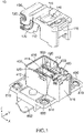
- a connector device 10 As shown in Fig. 1 , a connector device 10 according to an embodiment of the present invention comprises a connector 100 and a mating connector 400. Referring to Fig. 15 , the connector 100 and the mating connector 400 are mateable with each other.
- the mating connector 400 is attached to an object such as an electric car (not shown) and is connected between a power system (not shown) and a motor (not shown).
- the mating connector 400 comprises a mating housing 410 made of insulator, two mating power terminals 500 each made of metal, a mating sub-housing 600 made of insulator, two mating detection terminals 700 each made of metal, four eyelets 810 each made of elastomer and two nuts 820 each made of metal.
- the mating housing 410 has two sidewalls 412, a rear end portion 416, a holding portion 418 and a flange 490.
- the sidewalls 412 are located at opposite sides of the mating housing 410 in a lateral direction (Y-direction), respectively.
- Each of the sidewalls 412 extends along a first perpendicular plane (perpendicular plane: XZ-plane).
- the rear end portion 416 is located at a rear end, or the positive X-side end, of the mating housing 410 in a front-rear direction (X-direction).
- the rear end portion 416 extends along a second perpendicular plane (YZ-plane).
- the holding portion 418 is located at a middle part of the mating housing 410 in each of the X-direction and the Y-direction.
- the flange 490 is located at a lower end, or the negative Z-side end, of the mating housing 410 in an upper-lower direction (Z-direction). Referring to Fig. 1 , the eyelets 810 are attached to the flange 490.
- the mating housing 410 is formed with two mating axis portions (shafts) 420 and two guided projections 430.
- the mating axis portions 420 are provided so as to correspond to the two sidewalls 412, respectively, and are located at positions same as each other in each of the X-direction and the Z-direction.
- Each of the mating axis portions 420 is a shaft extending in an axial direction in parallel to the Y-direction.
- Each of the mating axis portions 420 is located in the vicinity of a front end, or the negative X-side end, of the corresponding sidewall 412 and extends inward in the Y-direction to the holding portion 418.
- the guided projections 430 are provided so as to correspond to the two sidewalls 412, respectively, and are located at positions same as each other in each of the X-direction and the Z-direction.
- Each of the guided projections 430 is a projection projecting inward in the Y-direction.
- the guided projections 430 are located between the mating axis portions (shafts) 420 and the rear end portion 416 in the X-direction.
- the mating power terminals 500 have shapes same as each other.
- Each of the mating power terminals 500 has a body portion 510 and a connection portion 590.
- the body portion 510 has a cylindrical shape extending in the Z-direction.
- the connection portion 590 extends outward in the Y-direction from a lower end of the body portion 510.
- the body portion 510 is provided with four contact points 520. Two of the contact points 520 face remaining two of the contact points 520 in the Y-direction, respectively.
- Each of the contact points 520 is supported by a spring portion to be movable in the Y-direction.
- the mating power terminals 500 are arranged mirror-symmetrically with respect to the XZ-plane. Moreover, the mating power terminals 500 are held inside the holding portion 418 of the mating housing 410 and fixed thereto. Thus, each of the mating power terminals 500 is held by the mating housing 410 and is unmovable relative to the mating housing 410. Referring to Fig. 7 , each of the connection portions 590 of the mating power terminals 500 is connected to a busbar 892 by using a bolt 898 and the nut 820.
- the mating sub-housing 600 has a rectangular column shape extending in the Z-direction.
- the mating sub-housing 600 has two holding holes 610 which are formed therewithin and arranged in the Y-direction. Each of the holding holes 610 extends along the Z-direction and opens downward, or in the negative Z-direction.
- the mating sub-housing 600 has a peripheral wall 620 and a cover 630.
- the peripheral wall 620 encloses the holding holes 610 in a horizontal plane (XY-plane).
- the cover 630 is located at an upper end, or the positive Z-side end, of the mating sub-housing 600.
- the cover 630 is formed with two openings 632.
- Each of the openings 632 is a space enclosed by four sloping surfaces and is gradually narrowed downward.
- the openings 632 correspond to the two holding holes 610, respectively.
- Each of the openings 632 is connected to the corresponding holding hole 610 in the Z-direction. In other words, each of the holding holes 610 opens upward, or in the positive Z-direction, through the corresponding opening 632.
- the mating detection terminals 700 have shapes same as each other.
- Each of the mating detection terminals 700 has a mating contact portion 710.
- the mating contact portion 710 is located in the vicinity of an upper end of the mating detection terminal 700 and is supported by a spring portion to be movable in the Y-direction.
- Each of the mating detection terminals 700 has a lower end connected to a signal cable 894.
- the mating detection terminals 700 are arranged in the same orientation in the Y-direction.
- the mating detection terminals 700 are held inside the holding holes 610 of the mating sub-housing 600, respectively, to be fixed thereto.
- each of the mating detection terminals 700 is held by the mating sub-housing 600 and is unmovable relative to the mating sub-housing 600.
- the mating housing 410 is formed with a receiving portion 440.
- the receiving portion 440 is a space which is located rearward of the holding portion 418.
- the mating sub-housing 600 is received in the receiving portion 440 and is held by the mating housing 410 to be unmovable. Therefore, each of the mating detection terminals 700 is held by the mating housing 410 via the mating sub-housing 600 and is unmovable relative to the mating housing 410.
- the mating sub-housing 600 which holds the mating detection terminals 700 is a member separable from the mating housing 410.
- the present invention is not limited thereto, but the mating sub-housing 600 and the mating housing 410 may form a single member. More specifically, a part of the mating housing 410 may be formed to have a shape similar to that of the mating sub-housing 600 so that the mating detection terminals 700 are directly held by the mating housing 410.
- the cover 630 of the mating sub-housing 600 covers the mating detection terminals 700 from above in the Z-direction. Nevertheless, the mating contact portions 710 of the mating detection terminals 700 are visible from above through the openings 632 of the cover 630.
- the cover 630 is a part of the mating sub-housing 600.
- the present invention is not limited thereto.
- the cover 630 may be a part of the mating housing 410.
- the mating housing 410 may be provided with the cover 630 which covers the mating detection terminals 700 from above in the Z-direction.
- the mating housing 410 has two partition walls 460.
- Each of the partition walls 460 has a flat-plate shape perpendicular to the Y-direction and extends in the Z-direction.
- the two partition walls 460 have shapes mirror symmetrical to each other with respect to the XZ-plane.
- the partition walls 460 are arranged in the Y-direction and sandwich the mating sub-housing 600 in the Y-direction.
- each of the partition walls 460 has a sloping surface 462, a first wall surface (first regulation portion) 472 and a second wall surface (second regulation portion) 474.
- the mating housing 410 has the two sloping surfaces 462, the two first wall surfaces 472 and the two second wall surfaces 474.
- the sloping surface 462 is a front part (negative X-side part) of an upper surface (positive Z-side surface) of the partition wall 460.
- the sloping surface 462 extends forward, or in the negative X-direction, while sloping downward. In other words, the sloping surface 462 is oblique to the Z-direction.
- the first wall surface 472 is a front surface, or the negative X-side surface, of the partition wall 460 and extends downward from a front end of the sloping surface 462 along the Z-direction.
- the second wall surface 474 is a rear surface, or the positive X-side surface, of the partition wall 460 and extends downward from a rear end of the upper surface of the partition wall 460 along the Z-direction.
- the mating housing 410 has a facing wall surface (second regulation portion) 480.
- the facing wall surface 480 is a rear surface of the holding portion 418.
- the facing wall surface 480 extends along the Z-direction while being curved in the XY-plane.
- the facing wall surface 480 faces the two first wall surfaces 472 across a guide channel 452 in the X-direction.
- Each of the first wall surfaces 472 is located rearward of the facing wall surface 480 across the guide channel 452 and is located at a position same as that of a front surface of the peripheral wall 620 of the mating sub-housing 600 in the X-direction.
- the guide channel 452 is a space which extends in the Z-direction and opens upward. In the X-direction, the guide channel 452 is located between the facing wall surface 480 and a series of surfaces consisting of the two first wall surfaces 472 and the front surface of the peripheral wall 620.
- the connector 100 comprises a housing 110 made of insulator, a power terminal 200 made of metal, a sub-housing 300 made of insulator and a detection terminal 390 made of metal.
- the housing 110 has two side portions 112.
- the side portions 112 are located at opposite sides of the housing 110 in the Y-direction, respectively. Each of the side portions 112 extends along the XZ-plane.
- the housing 110 is formed with two axis portions (bearings) 120 and two guide recesses 130.
- the axis portions 120 are provided so as to correspond to the two side portions 112, respectively.
- Each of the axis portions 120 is a bearing which is a hole passing through the corresponding side portion 112 in the Y-direction.
- the two axis portions 120 are located at positions same as each other in each of the X-direction and the Z-direction.
- the guide recesses 130 are provided so as to correspond to the two side portions 112, respectively.
- Each of the guide recesses 130 is a groove which is formed on the corresponding side portion 112 to be recessed inward in the Y-direction.
- Each of the guide recesses 130 has an arch-shape in the XZ-plane.
- the two guide recesses 130 are located at positions same as each other in each of the X-direction and the Z-direction.
- each of the axis portions 120 of the housing 110 is the bearing, and each of the mating axis portions 420 of the mating housing 410 is the shaft.
- the housing 110 of the present embodiment is turnable about the mating axis portions 420.
- each of the axis portions 120 may be a shaft, and each of the mating axis portions 420 may be a bearing.
- one of the axis portion 120 and the mating axis portion 420 may be a shaft and a remaining one of the axis portion 120 and the mating axis portion 420 may be a bearing.
- each part of the connector 100 changes its position in the XZ-plane as the housing 110 is turned.
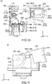
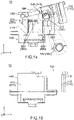
- the housing 110 is turned between an open position shown in Fig. 7 and a close position shown in Fig. 15 via an intermediate position shown in Fig. 11 .
- a positional feature of each part of the connector 100 in the XZ-plane is specified by using "radial direction” and "circumference direction".
- the radial direction is a direction along a radius of an imaginary circle around the axis portion 120 (see Fig. 1 ) in the XZ-plane
- the circumference direction is another direction along the circumference of the imaginary circle.
- each of the radial direction and the circumference direction is a direction about the shafts, or the axis portions 120 of the housing 110.
- Each of the radial direction and the circumference direction is perpendicular to the Y-direction.
- the radial direction and the circumference direction are perpendicular to each other.
- the housing 110 has a base portion 116 and an accommodation portion 140.
- the base portion 116 is a part which is farthest from the axis portions 120 in the radial direction.
- the base portion 116 extends along a plane perpendicular to the radial direction.
- the accommodation portion 140 is located between the axis portions 120 and the base portion 116 of the housing 110 in the radial direction.
- the accommodation portion 140 has a first wall 142, a second wall 144 and two third walls 148.
- the first wall 142 extends along a plane defined by the radial direction and the axial direction (Y-direction).
- the second wall 144 is farthest from the axis portions 120 in the radial direction.
- the second wall 144 extends along a plane perpendicular to the radial direction.
- the third walls 148 are located at opposite sides of the accommodation portion 140 in the Y-direction, respectively. Each of the third walls 148 extends along the XZ-plane.
- the housing 110 is formed with two sub-bearings 150.
- the sub-bearings 150 are provided so as to correspond to the two third walls 148, respectively.
- the two sub-bearings 150 are located at positions same as each other in each of the X-direction and the Z-direction.
- each of the sub-bearings 150 is a hole which passes through the corresponding third wall 148 in the Y-direction.
- the present invention is not limited thereto.
- each of the sub-bearings 150 may be a recess which is formed on an inner wall surface of the corresponding third wall 148.
- the housing 110 has a first movement regulation portion 162 and a second movement regulation portion 164.
- the first movement regulation portion 162 is an inner wall surface of the first wall 142 of the accommodation portion 140.
- the first movement regulation portion 162 extends along a plane defined by the radial direction and the axial direction (Y-direction).
- the second movement regulation portion 164 is an inner wall surface of the second wall 144 of the accommodation portion 140.
- the second movement regulation portion 164 extends along a plane perpendicular to the radial direction.
- the first movement regulation portion 162 is located in a plane perpendicular to the second movement regulation portion 164.
- the first movement regulation portion 162 is nearer to the axis portions 120 in the radial direction than the second movement regulation portion 164.
- the power terminal 200 has a coupling portion 210 and two blades 220. Each of the blades 220 extends along the XZ-plane.
- the coupling portion 210 couples the two blades 220 to each other in the Y-direction.
- the power terminal 200 is held by the housing 110 so that the blades 220 are arranged in the Y-direction.
- the power terminal 200 is fixed to the housing 110 and is unmovable relative to the housing 110.
- the sub-housing 300 has two side plates 340.
- the side plates 340 are located at opposite sides of the sub-housing 300 in the Y-direction, respectively.
- Each of the side plates 340 extends along the XZ-plane.
- the sub-housing 300 is formed with two sub-shafts 350.
- Each of the sub-shafts 350 is a shaft extending in parallel to the axial direction (Y-direction).
- the sub-shafts 350 are provided so as to correspond to the two side plates 340, respectively, and are located at positions same as each other in each of the X-direction and the Z-direction.
- Each of the sub-shafts 350 has a circular shape in the XZ-plane and projects outward in the Y-direction from the corresponding side plate 340.
- the sub-housing 300 is partially accommodated inside the accommodation portion 140 of the housing 110.
- the sub-shafts 350 of the sub-housing 300 are inserted into the sub-bearings 150 of the accommodation portion 140, respectively, so that the two side plates 340 are sandwiched between the two third walls 148 of the accommodation portion 140 in the Y-direction to receive inward spring forces in the Y-direction from the third walls 148.
- the sub-housing 300 is supported by the housing 110.
- the sub-housing 300 is supported only by the sub-bearings 150 except for the aforementioned spring forces.
- a gap is formed between the sub-housing 300 and an inner wall surface of the accommodation portion 140 in the XZ-plane. Therefore, the sub-housing 300 is movable relative to the housing 110 to some extent. In other words, the sub-bearings 150 receive the sub-shafts 350, respectively, so that the sub-housing 300 is movable along the XZ-plane.
- each of the sub-bearings 150 is a long hole which extends long in the radial direction.
- Each of the circular sub-shafts 350 is movable inside the corresponding sub-bearing 150 along the radial direction and is rotatable clockwise and counterclockwise inside the corresponding sub-bearing 150. Therefore, the sub-housing 300 is slidable along the sub-bearings 150 relative to the housing 110 and is pivotally movable about the sub-shafts 350 relative to the housing 110 in each of opposite pivoting directions.
- the sub-housing 300 is supported by the housing 110 so as to be movable relative to the housing 110.
- the sub-housing 300 of the present embodiment is swingingly movable along the XZ-plane but is almost unmovable in the Y-direction.
- the present invention is not limited thereto.
- the sub-housing 300 may be only slidable along the sub-bearings 150.
- each of the sub-bearings 150 may extend along the radial direction longer than that of the present embodiment, and each of the sub-shafts 350 may have a rounded rectangular shape in the XZ-plane.
- the sub-housing 300 may be movable along the XZ-plane and movable in the Y-direction to some extent.
- each part of the sub-housing 300 changes its position in the XZ-plane as the sub-housing 300 is moved relative to the housing 110 except when the housing 110 is located at the close position, or the position shown in Fig. 17 .
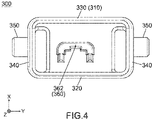
- Figs. 2 to 4 explanation is first made about a structure of the sub-housing 300 and the detection terminal 390 under a state where the housing 110 is located at the close position. Subsequently, explanation is made, by using the radial direction and the circumference direction, about a structure of the sub-housing 300 which holds the detection terminal 390 and is supported by the housing 110.
- the sub-housing 300 has a rectangular cylindrical portion 310 and a terminal holding portion 360.
- the rectangular cylindrical portion 310 has a rectangular cylindrical shape which extends in the Z-direction and opens at a lower end thereof.
- the terminal holding portion 360 is located in the vicinity of an upper end of the rectangular cylindrical portion 310 and is enclosed by the rectangular cylindrical portion 310 in the XY-plane.
- the terminal holding portion 360 is formed with a holding hole 362.
- the sub-housing 300 has a front plate (guided portion) 320 and a rear plate 330 in addition to the side plates 340.
- each of the front plate 320, the rear plate 330 and the side plates 340 is a part of the rectangular cylindrical portion 310.
- the front plate 320 is a front wall of the rectangular cylindrical portion 310
- the rear plate 330 is a rear wall (positive X-side wall) of the rectangular cylindrical portion 310.
- the side plates 340 are two sidewalls of the rectangular cylindrical portion 310.
- the sub-housing 300 may have no side plate 340.
- the sub-shafts 350 may be provided on the terminal holding portion 360.
- the sub-housing 300 has two first movement regulated portions 342, a first movement regulated portion 344 and a second movement regulated portion 346.
- the first movement regulated portions 342 are provided so as to correspond to the two side plates 340, respectively, and are located at positions same as each other in each of the X-direction and the Z-direction. Under the illustrated state, each of the first movement regulated portions 342 is a front part of an upper edge of the corresponding side plate 340 and is oblique to both the X-direction and the Z-direction. More specifically, each of the first movement regulated portions 342 extends forward while sloping downward.
- the first movement regulated portion 344 is a part of a rear surface of the rear plate 330 which is located in the vicinity of an upper end thereof and is oblique to both the X-direction and the Z-direction. More specifically, the first movement regulated portion 344 extends rearward, or in the positive X-direction, while sloping downward.
- the second movement regulated portion 346 is a lower part of the rear surface of the rear plate 330 which is located below the first movement regulated portion 344 and is perpendicular to the X-direction.
- the detection terminal 390 has a held portion 392 and two contact portions 394.
- the held portion 392 couples the two contact portions 394 to each other in the Y-direction. Under the illustrated state, each of the contact portions 394 linearly extends downward from the held portion 392.
- the held portion 392 is press-fit into and held by the holding hole 362 of the sub-housing 300.
- the detection terminal 390 is held by the sub-housing 300 so that the contact portions 394 are arranged in the Y-direction.
- the detection terminal 390 is fixed to the sub-housing 300 and is unmovable relative to the sub-housing 300.
- the front plate 320 of the rectangular cylindrical portion 310 is nearer to the axis portions 120 in the radial direction than the detection terminal 390 and any other part of the rectangular cylindrical portion 310.
- the rear plate 330 of the rectangular cylindrical portion 310 is farther from the axis portions 120 in the radial direction than the detection terminal 390 and any other part of the rectangular cylindrical portion 310.
- each of the first movement regulated portions 342 of the sub-housing 300 is located in a plane intersecting with each of the first movement regulated portion 344 and the second movement regulated portion 346. Moreover, each of the first movement regulated portions 342 is nearer to the axis portions 120 in the radial direction than the first movement regulated portion 344 and the second movement regulated portion 346.
- the housing 110 is turnable about the shafts, or the mating axis portions 420, between the open position, or the position shown in Fig. 7 , and the close position, or the position shown in Fig. 11 , via the intermediate position, or the position shown in Fig. 15 .
- a state which the connector 100 takes when the housing 110 is located at the open position is referred to as "unconnected state”
- a state which the connector 100 takes when the housing 110 is located at the close position is referred to as "connected state”.
- intermediate state a state which the connector 100 takes when the housing 110 is located at the intermediate position.
- intermediate state a state which the connector 100 takes when the housing 110 is located at the intermediate position.
- a positional feature of each part of the connector device 10 in the XZ-plane is specified by using a radial direction and a circumference direction about the mating axis portions 420.
- the radial direction is a direction along a radius of an imaginary circle around the mating axis portions 420 in the XZ-plane
- the circumference direction is another direction along a circumference of the imaginary circle in the XZ-plane.
- each of "clockwise turn” and “counterclockwise turn” specifies a turning direction of the connector 100 of the connector device 10 that is seen along the positive Y-direction.
- the connector 100 which is in a standing posture relative to the mating connector 400, is attached to the mating connector 400 along the negative Z-direction from above the mating connector 400.
- This operation changes the state of the connector 100 from a separated state, in which the connector 100 is apart from the mating connector 400 as shown in Fig. 1 , to the unconnected state in which the connector 100 is partially mated with the mating connector 400 as shown in Figs. 7 to 10 .
- the power terminal 200 is unconnected to the mating power terminals 500.
- the detection terminal 390 is unconnected to the mating detection terminals 700.
- the power terminal 200 is connected to the two mating power terminals 500 so that the mating power terminals 500 are connected with each other.
- each of the blades 220 of the power terminal 200 is inserted inside the body portion 510 of the corresponding mating power terminal 500, to be sandwiched between the contact points 520 in the Y-direction and to be in contact with the contact points 520.
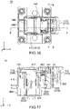
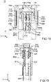
- the detection terminal 390 is unconnected to the mating detection terminals 700 so that the two signal cables 894 (see Fig. 18 ) are unconnected with each other.
- the power system (not shown) makes control so that electric current does not flow through the busbar 892 (see Fig. 1 ).
- a maintenance mechanism 14 provided to the connector device 10 prevents a counterclockwise turn of the housing 110 and maintains the connected state of the connector 100.
- the power terminal 200 is connected to the two mating power terminals 500.
- the contact portions 394 of the detection terminal 390 pass through the openings 632 along the Z-direction, respectively, and are in contact with the mating contact portions 710 of the mating detection terminals 700, respectively.
- the detection terminal 390 is connected to the two mating detection terminals 700 so that the mating detection terminals 700 are connected with each other.
- the sub-housing 300 is completely mated with the mating sub-housing 600, so that the connector 100 is completely mated with the mating connector 400.
- the power system (not shown) makes control so that electric current flows through the busbar 892 (see Fig. 1 ).
- the connector device 10 connects the power system and the motor (not shown) with each other so that the power system supplies electric current to the motor.
- the state of the connector 100 according to the present embodiment is changed between the unconnected state and the connected state via the intermediate state.
- the intermediate state of the present embodiment can be defined as a temporarily maintained state of the connector 100 in which the state of the connector 100 is temporarily maintained by the temporal regulation mechanism 12.
- the intermediate state is not limited to the temporarily maintained state.
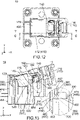
- the power terminal 200 is already connected to the mating power terminals 500 when the housing 110 is turned to the position of Fig. 13 . In other words, the power terminal 200 starts to be connected to the mating power terminals 500 while the housing 110 is turned from the open position of Fig. 10 to the intermediate position of Fig. 13 .
- the intermediate state may be defined as a state of the connector 100 at a timing when the power terminal 200 starts to be connected to the mating power terminals 500.
- each of the temporal regulation mechanism 12 and the maintenance mechanism 14 may be provided as necessary.
- the mating housing 410 has a guide portion 450.
- the guide portion 450 guides the sub-housing 300, which is movable relative to the turnable housing 110, and linearly moves the sub-housing 300 along the Z-direction.
- the housing 110 has a movement regulation portion 160.
- the movement regulation portion 160 regulates a movement of the sub-housing 300 and defines a movable range of the sub-housing 300.
- explanation is first made about the movement regulation portion 160 and subsequently made about the guide portion 450.
- the movement regulation portion 160 of the housing 110 includes the first movement regulation portion 162 and the second movement regulation portion 164 which are previously described.
- the first movement regulation portion 162 faces the first movement regulated portions 342 with a slight gap therebetween in the circumference direction.
- the second movement regulation portion 164 faces the first movement regulated portion 344 and the second movement regulated portion 346 with a slight gap therebetween in the radial direction.
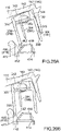
- the first movement regulation portion 162 regulates a pivoting movement of the first movement regulated portions 342 about the sub-shafts 350 (see Fig. 14 ) in a first direction, or a clockwise direction in Fig. 10 , when the state of the connector 100 is between the unconnected state and the intermediate state.
- the second movement regulation portion 164 regulates a pivoting movement of the first movement regulated portion 344 in the first direction. More specifically, the sub-housing 300 is pivotally movable about the sub-shafts 350 to a first limit position in the first direction.
- the first limit position is a position at which the first movement regulated portion 342 is brought into contact with the first movement regulation portion 162 or at which the first movement regulated portion 344 is brought into contact with the second movement regulation portion 164.
- the sub-housing 300 cannot be pivotally moved beyond the first limit position.
- the second movement regulation portion 164 regulates a pivoting movement of the second movement regulated portion 346 about the sub-shafts 350 (see Fig. 14 ) in a second direction, or a counterclockwise direction in Fig. 10 , when the state of the connector 100 is between the unconnected state and the intermediate state. More specifically, the sub-housing 300 is pivotally movable about the sub-shafts 350 in the second direction to a second limit position at which the second movement regulated portion 346 is brought into contact with the second movement regulation portion 164. The sub-housing 300 cannot be pivotally moved beyond the second limit position.
- each of the first movement regulation portion 162 and the second movement regulation portion 164 regulates a movement of the sub-housing 300 in the first direction in parallel to the XZ-plane.
- the second movement regulation portion 164 regulates another movement of the sub-housing 300 in the second direction which is in parallel to the XZ-plane but different from the first direction.
- the first direction is one of the opposite pivoting directions of the sub-housing 300 about the sub-shafts 350 (see Fig. 14 ), and the second direction is a remaining one of the opposite pivoting directions of the sub-housing 300 about the sub-shafts 350.
- the first movement regulation portion 162 and the second movement regulation portion 164 of the movement regulation portion 160 define a movable range of the pivoting movement of the sub-housing 300.
- the movement regulation portion 160 includes the sub-bearings 150.
- the sub-bearings 150 define another movable range of a sliding movement of the sub-housing 300 in the radial direction.
- the sub-housing 300 is movable within the movable range defined by the movement regulation portion 160 in the XZ-plane but cannot be moved beyond the movable range.
- the movement regulation portion 160 consists of the first movement regulation portion 162, the second movement regulation portion 164 and the sub-bearings 150.
- the present invention is not limited thereto, but the movement regulation portion 160 may be formed variously.
- the second movement regulation portion 164 may regulate a sliding movement of the sub-housing 300 in an orientation away from the axis portions 120 in the radial direction.
- the housing 110 may have, in addition to the sub-bearings 150, a movement regulation portion which regulates another sliding movement of the sub-housing 300 in another orientation approaching the axis portions 120 in the radial direction.
- the guide portion 450 of the mating housing 410 includes the sloping surfaces 462, the first regulation portions (first wall surfaces) 472 and the second regulation portion (facing wall surface) 480.
- the front plate 320 works as the guided portion 320 which is guided by the guide portion 450.
- the aforementioned movement regulation portion 160 restricts the movable range of the sub-housing 300 relative to the housing 110 within a range within which the guide portion 450 can guide the guided portion 320.
- the front plate 320 of the sub-housing 300 is brought into contact with the facing wall surface 480 to be guided to the guide channel 452 while the state of the connector 100 is changed to the connected state.
- the front plate 320 is brought into contact with the sloping surfaces 462 or the facing wall surface 480 to be guided.
- the front plate 320 of the present embodiment is brought into contact with the sloping surfaces 462 or the facing wall surface 480 while the state of the connector 100 is changed from the unconnected state to the intermediate state.
- the present invention is not limited thereto.
- the front plate 320 may be brought into contact with the sloping surfaces 462 or the facing wall surface 480 while the state of the connector 100 is changed from the intermediate state to the connected state.
- the front plate 320 may be brought into contact with a sloping upper surface of the holding portion 418 to be guided to the guide channel 452.
- a part other than the front plate 320 may work as the guided portion.
- the rear plate 330 may be designed to work as the guided portion.
- each of the first wall surfaces 472 works as the first regulation portion 472 and regulates a rearward movement of the sub-housing 300 while the state of the connector 100 is changed from the intermediate state to the connected state.
- the facing wall surface 480 works as the second regulation portion 480 and regulates a forward movement of the sub-housing 300 while the state of the connector 100 is changed from the intermediate state to the connected state.
- each of the first regulation portions 472 and the second regulation portion 480 regulates the movement of the guided portion 320 in the X-direction mainly while the state of the connector 100 is changed from the intermediate state to the connected state.
- each of the first regulation portions 472 and the second regulation portion 480 may regulate the movement of the guided portion 320 in the X-direction also while the state of the connector 100 is changed from the unconnected state to the intermediate state.
- each of the first regulation portion and the second regulation portion may be a part other than the first wall surfaces 472 and the facing wall surface 480, provided that each of the first regulation portion and the second regulation portion is located rearward of the mating axis portions 420.
- the second wall surface 474 of each of the partition walls 460 may work as the second regulation portion 474.
- the guide portion 450 may include the second regulation portions 474 instead of the second regulation portion 480 or in addition to the second regulation portion 480.
- each of the second wall surfaces 474 may regulate a forward movement of the rear plate 330 of the sub-housing 300 while the state of the connector 100 is changed to the connected state.
- an upper part of each of the second wall surfaces 474 which is located above the mating sub-housing 600 in the Z-direction, is preferred to be a sloping surface which extends to a rear surface of the mating sub-housing 600 in the X-direction.
- a lower end of the upper part of each of the second wall surfaces 474 is preferred to be located at a position in the X-direction same as a position of an upper end of the rear surface of the mating sub-housing 600 in the X-direction.
- the guide portion 450 which includes the second wall surfaces 474 and the facing wall surface 480, guides the guided portion 320 as described above while the state of the connector 100 is changed from the intermediate state to the connected state, so that ends of the detection terminal 390, or lower ends of the contact portions 394 in Fig. 13 , face the openings 632 in the Z-direction, respectively, and are then moved to the cover 630 of the sub-housing 300.
- each of the ends of the detection terminal 390 faces a corresponding one of the openings 632 in the Z-direction when the each end of the detection terminal 390 is moved to be located at a position same as that of an upper end of the corresponding opening 632 in the Z-direction.
- the each end of the detection terminal 390 is located at a position almost same as that of a corresponding one of the mating detection terminals 700 in each of the X-direction and the Y-direction.
- the ends of the detection terminal 390 almost face the openings 632, respectively, at a timing when the state of the connector 100 is just changed to the intermediate state.
- the present invention is not limited thereto.
- the ends of the detection terminal 390 may face the openings 632, respectively, only while the state of the connector 100 is changed from the intermediate state to the connected state.
- the rectangular cylindrical portion 310 of the sub-housing 300 opens toward the mating detection terminals 700 in a clockwise direction along which the housing 110 is turned so that the state of the connector 100 is changed to the connected state.
- the rectangular cylindrical portion 310 is linearly moved downward along the Z-direction while enclosing the mating sub-housing 600 and the partition walls 460 in the XY-plane.
- the mating sub-housing 600 and the partition walls 460 as a whole guide the rectangular cylindrical portion 310 and convert a turning movement of the housing 110 into a linear movement of the sub-housing 300.
- the rectangular cylindrical portion 310 of the sub-housing 300 encloses the mating sub-housing 600 and the partition walls 460 in the XY-plane. Thereafter, the sub-housing 300 is moved downward along the Z-direction relative to the mating sub-housing 600, while the sub-housing 300 is hardly moved in any of the X-direction and the Y-direction relative to the mating sub-housing 600. However, the sub-housing 300 is slightly moved relative to the housing 110 in the X-direction.
- the ends of the detection terminal 390 face the openings 632, respectively. Therefore, even if each of the ends of the detection terminal 390 is brought into abutment with one of the sloping surfaces of the corresponding opening 632, the each end of the detection terminal 390 is guided to the corresponding holding hole 610 by the sloping surface.
- the contact portions 394 of the detection terminal 390 are linearly moved downward, or toward the mating contact portions 710 of the mating detection terminals 700, respectively, to be brought into contact with the mating contact portions 710, respectively.
- the guide portion 450 guides the guided portion 320 to move the sub-housing 300 relative to the housing 110.
- the detection terminal 390 is moved downward along the Z-direction to be connected to the mating detection terminals 700.
- the sub-housing 300 is movable relative to the mating housing 410 with no cam mechanism.
- the detection terminal 390 is a pin terminal with the two contact portions 394 each having a pin-shape, and each of the mating detection terminals 700 is a socket terminal.
- the present invention is not limited thereto, but the detection terminal 390 may be a socket terminal, and each of the mating detection terminals 700 may be a pin terminal.
Landscapes
- Engineering & Computer Science (AREA)
- Mechanical Engineering (AREA)
- Details Of Connecting Devices For Male And Female Coupling (AREA)
Applications Claiming Priority (1)
| Application Number | Priority Date | Filing Date | Title |
|---|---|---|---|
| JP2017157997A JP6840640B2 (ja) | 2017-08-18 | 2017-08-18 | コネクタ装置 |
Publications (2)
| Publication Number | Publication Date |
|---|---|
| EP3444906A1 EP3444906A1 (en) | 2019-02-20 |
| EP3444906B1 true EP3444906B1 (en) | 2022-05-11 |
Family
ID=62909399
Family Applications (1)
| Application Number | Title | Priority Date | Filing Date |
|---|---|---|---|
| EP18182557.1A Active EP3444906B1 (en) | 2017-08-18 | 2018-07-09 | Connector device |
Country Status (4)
| Country | Link |
|---|---|
| US (1) | US10320119B2 (cg-RX-API-DMAC7.html) |
| EP (1) | EP3444906B1 (cg-RX-API-DMAC7.html) |
| JP (1) | JP6840640B2 (cg-RX-API-DMAC7.html) |
| CN (1) | CN109411936B (cg-RX-API-DMAC7.html) |
Families Citing this family (15)
| Publication number | Priority date | Publication date | Assignee | Title |
|---|---|---|---|---|
| CN210239261U (zh) | 2019-05-21 | 2020-04-03 | 明达实业(厦门)有限公司 | 一种水池清洁器的轮刷固定结构 |
| JP7032002B2 (ja) * | 2020-02-05 | 2022-03-08 | 矢崎総業株式会社 | 電源回路遮断装置 |
| JP7507084B2 (ja) * | 2020-12-25 | 2024-06-27 | 日本航空電子工業株式会社 | コネクタ装置 |
| JP7444116B2 (ja) * | 2021-03-16 | 2024-03-06 | 住友電装株式会社 | コネクタ |
| JP1703914S (cg-RX-API-DMAC7.html) * | 2021-06-08 | 2022-01-04 | ||
| JP1703912S (cg-RX-API-DMAC7.html) * | 2021-06-08 | 2022-01-04 | ||
| JP1730750S (ja) * | 2022-05-20 | 2022-11-28 | コネクタ | |
| JP1730752S (ja) * | 2022-05-20 | 2022-11-28 | コネクタ | |
| JP1730753S (ja) * | 2022-05-20 | 2022-11-28 | コネクタ | |
| JP1730796S (ja) * | 2022-05-20 | 2022-11-28 | コネクタ | |
| JP1730751S (ja) * | 2022-05-20 | 2022-11-28 | コネクタ | |
| JP1730754S (ja) * | 2022-05-20 | 2022-11-28 | コネクタ | |
| JP1742942S (ja) * | 2022-09-06 | 2023-04-26 | コネクタ | |
| JP1742941S (ja) * | 2022-09-06 | 2023-04-26 | コネクタ | |
| JP7881456B2 (ja) * | 2022-11-17 | 2026-06-29 | 日本航空電子工業株式会社 | コネクタ装置 |
Family Cites Families (25)
| Publication number | Priority date | Publication date | Assignee | Title |
|---|---|---|---|---|
| US5417586A (en) * | 1993-04-14 | 1995-05-23 | Yazaki Corporation | Fitting detection connector |
| JP3948499B2 (ja) * | 1994-06-01 | 2007-07-25 | 矢崎総業株式会社 | コネクタ装置 |
| JPH1174023A (ja) * | 1997-08-29 | 1999-03-16 | Yazaki Corp | レバー嵌合式コネクタの嵌合検知構造 |
| JP3820354B2 (ja) * | 2001-05-16 | 2006-09-13 | 矢崎総業株式会社 | レバー嵌合式電源回路遮断装置 |
| JP4678333B2 (ja) * | 2005-09-29 | 2011-04-27 | 住友電装株式会社 | レバー式コネクタ |
| DE602006009353D1 (de) * | 2005-09-29 | 2009-11-05 | Sumitomo Wiring Systems | Ein Steckverbinder mit einem bewegbaren Glied |
| JP4577209B2 (ja) * | 2005-12-26 | 2010-11-10 | 住友電装株式会社 | コネクタ |
| JP5162348B2 (ja) * | 2008-06-25 | 2013-03-13 | 矢崎総業株式会社 | レバー式コネクタ |
| JP5223777B2 (ja) * | 2009-05-27 | 2013-06-26 | 住友電装株式会社 | コネクタ |
| DE102009053674B4 (de) | 2009-11-19 | 2011-09-01 | Yazaki Europe Ltd. | Steckverbinder mit Sekundärsteckverbinder |
| JP5608488B2 (ja) * | 2010-09-09 | 2014-10-15 | 矢崎総業株式会社 | レバー嵌合式コネクタ |
| JP5626136B2 (ja) * | 2011-06-15 | 2014-11-19 | 住友電装株式会社 | 電源回路遮断装置 |
| JP2013016426A (ja) * | 2011-07-06 | 2013-01-24 | Sumitomo Wiring Syst Ltd | 回路遮断装置 |
| JP5858745B2 (ja) * | 2011-11-21 | 2016-02-10 | 矢崎総業株式会社 | 電源回路遮断装置 |
| JP5820289B2 (ja) * | 2012-02-08 | 2015-11-24 | 矢崎総業株式会社 | レバー式コネクタ |
| JP2014238929A (ja) | 2013-06-06 | 2014-12-18 | 日本航空電子工業株式会社 | コネクタ装置 |
| JP6193060B2 (ja) * | 2013-09-02 | 2017-09-06 | タイコエレクトロニクスジャパン合同会社 | レバー式電気コネクタ |
| JP6099203B2 (ja) * | 2013-09-03 | 2017-03-22 | 日本航空電子工業株式会社 | コネクタ装置 |
| JP2015053207A (ja) * | 2013-09-09 | 2015-03-19 | タイコエレクトロニクスジャパン合同会社 | レバー式電気コネクタ、及び、嵌合システム |
| JP6182515B2 (ja) | 2014-08-19 | 2017-08-16 | 日本航空電子工業株式会社 | コネクタ装置 |
| JP6540499B2 (ja) * | 2015-12-22 | 2019-07-10 | 住友電装株式会社 | コネクタ |
| JP6663790B2 (ja) | 2016-05-12 | 2020-03-13 | 日本航空電子工業株式会社 | コネクタ装置 |
| JP6692718B2 (ja) | 2016-08-16 | 2020-05-13 | 日本航空電子工業株式会社 | コネクタ装置 |
| JP6720061B2 (ja) * | 2016-11-18 | 2020-07-08 | 日本航空電子工業株式会社 | コネクタ装置 |
| JP6792424B2 (ja) | 2016-11-18 | 2020-11-25 | 日本航空電子工業株式会社 | コネクタ装置 |
-
2017
- 2017-08-18 JP JP2017157997A patent/JP6840640B2/ja active Active
-
2018
- 2018-06-28 US US16/021,252 patent/US10320119B2/en active Active
- 2018-07-09 EP EP18182557.1A patent/EP3444906B1/en active Active
- 2018-07-20 CN CN201810801607.8A patent/CN109411936B/zh active Active
Also Published As
| Publication number | Publication date |
|---|---|
| CN109411936B (zh) | 2020-07-03 |
| EP3444906A1 (en) | 2019-02-20 |
| US10320119B2 (en) | 2019-06-11 |
| JP2019036485A (ja) | 2019-03-07 |
| US20190058286A1 (en) | 2019-02-21 |
| JP6840640B2 (ja) | 2021-03-10 |
| CN109411936A (zh) | 2019-03-01 |
Similar Documents
| Publication | Publication Date | Title |
|---|---|---|
| US10320119B2 (en) | Connector device | |
| EP2086063B1 (en) | Service plug | |
| US6982393B2 (en) | Lever fitting-type power supply circuit breaker | |
| EP4020722B1 (en) | Connector device | |
| US9966701B2 (en) | Connector device | |
| US9893469B2 (en) | Connector device | |
| EP3425747B1 (en) | Connector | |
| US10008805B2 (en) | Connector device | |
| EP1830436B1 (en) | A connector, connector assembly and assembling method | |
| US20120231644A1 (en) | Vehicle charge cable socket connector | |
| EP3748659B1 (en) | Power circuit shut off device | |
| CN102769237A (zh) | 设备连接器 | |
| US9905965B2 (en) | Connector and connector assembly | |
| US20190221979A1 (en) | Rotary connector and fixing structure of rotary connector | |
| US20170093088A1 (en) | Connector and connector assembly | |
| WO2002101887A2 (en) | Shielded floating electrical connector | |
| EP3588691B1 (en) | Connector | |
| JP2008004287A (ja) | コネクタ | |
| US20210391665A1 (en) | Connector assembly and connector | |
| US20240145971A1 (en) | Electrical connector and switching device | |
| EP3404776B1 (en) | Lever fitting-type connector | |
| EP2726319B1 (en) | Enclosure and electrical socket comprising such an enclosure | |
| EP4621964A1 (en) | Battery pack and battery device comprising same | |
| JP3388187B2 (ja) | 電気接続箱 |
Legal Events
| Date | Code | Title | Description |
|---|---|---|---|
| PUAI | Public reference made under article 153(3) epc to a published international application that has entered the european phase |
Free format text: ORIGINAL CODE: 0009012 |
|
| STAA | Information on the status of an ep patent application or granted ep patent |
Free format text: STATUS: THE APPLICATION HAS BEEN PUBLISHED |
|
| AK | Designated contracting states |
Kind code of ref document: A1 Designated state(s): AL AT BE BG CH CY CZ DE DK EE ES FI FR GB GR HR HU IE IS IT LI LT LU LV MC MK MT NL NO PL PT RO RS SE SI SK SM TR |
|
| AX | Request for extension of the european patent |
Extension state: BA ME |
|
| STAA | Information on the status of an ep patent application or granted ep patent |
Free format text: STATUS: REQUEST FOR EXAMINATION WAS MADE |
|
| 17P | Request for examination filed |
Effective date: 20190227 |
|
| RBV | Designated contracting states (corrected) |
Designated state(s): AL AT BE BG CH CY CZ DE DK EE ES FI FR GB GR HR HU IE IS IT LI LT LU LV MC MK MT NL NO PL PT RO RS SE SI SK SM TR |
|
| GRAP | Despatch of communication of intention to grant a patent |
Free format text: ORIGINAL CODE: EPIDOSNIGR1 |
|
| STAA | Information on the status of an ep patent application or granted ep patent |
Free format text: STATUS: GRANT OF PATENT IS INTENDED |
|
| INTG | Intention to grant announced |
Effective date: 20210622 |
|
| GRAJ | Information related to disapproval of communication of intention to grant by the applicant or resumption of examination proceedings by the epo deleted |
Free format text: ORIGINAL CODE: EPIDOSDIGR1 |
|
| STAA | Information on the status of an ep patent application or granted ep patent |
Free format text: STATUS: REQUEST FOR EXAMINATION WAS MADE |
|
| GRAS | Grant fee paid |
Free format text: ORIGINAL CODE: EPIDOSNIGR3 |
|
| STAA | Information on the status of an ep patent application or granted ep patent |
Free format text: STATUS: GRANT OF PATENT IS INTENDED |
|
| GRAP | Despatch of communication of intention to grant a patent |
Free format text: ORIGINAL CODE: EPIDOSNIGR1 |
|
| INTC | Intention to grant announced (deleted) | ||
| INTG | Intention to grant announced |
Effective date: 20211109 |
|
| GRAA | (expected) grant |
Free format text: ORIGINAL CODE: 0009210 |
|
| STAA | Information on the status of an ep patent application or granted ep patent |
Free format text: STATUS: THE PATENT HAS BEEN GRANTED |
|
| AK | Designated contracting states |
Kind code of ref document: B1 Designated state(s): AL AT BE BG CH CY CZ DE DK EE ES FI FR GB GR HR HU IE IS IT LI LT LU LV MC MK MT NL NO PL PT RO RS SE SI SK SM TR |
|
| REG | Reference to a national code |
Ref country code: GB Ref legal event code: FG4D |
|
| REG | Reference to a national code |
Ref country code: CH Ref legal event code: EP |
|
| REG | Reference to a national code |
Ref country code: AT Ref legal event code: REF Ref document number: 1492267 Country of ref document: AT Kind code of ref document: T Effective date: 20220515 |
|
| REG | Reference to a national code |
Ref country code: DE Ref legal event code: R096 Ref document number: 602018035292 Country of ref document: DE |
|
| REG | Reference to a national code |
Ref country code: IE Ref legal event code: FG4D |
|
| REG | Reference to a national code |
Ref country code: LT Ref legal event code: MG9D |
|
| REG | Reference to a national code |
Ref country code: NL Ref legal event code: MP Effective date: 20220511 |
|
| REG | Reference to a national code |
Ref country code: AT Ref legal event code: MK05 Ref document number: 1492267 Country of ref document: AT Kind code of ref document: T Effective date: 20220511 |
|
| PG25 | Lapsed in a contracting state [announced via postgrant information from national office to epo] |
Ref country code: SE Free format text: LAPSE BECAUSE OF FAILURE TO SUBMIT A TRANSLATION OF THE DESCRIPTION OR TO PAY THE FEE WITHIN THE PRESCRIBED TIME-LIMIT Effective date: 20220511 Ref country code: PT Free format text: LAPSE BECAUSE OF FAILURE TO SUBMIT A TRANSLATION OF THE DESCRIPTION OR TO PAY THE FEE WITHIN THE PRESCRIBED TIME-LIMIT Effective date: 20220912 Ref country code: NO Free format text: LAPSE BECAUSE OF FAILURE TO SUBMIT A TRANSLATION OF THE DESCRIPTION OR TO PAY THE FEE WITHIN THE PRESCRIBED TIME-LIMIT Effective date: 20220811 Ref country code: NL Free format text: LAPSE BECAUSE OF FAILURE TO SUBMIT A TRANSLATION OF THE DESCRIPTION OR TO PAY THE FEE WITHIN THE PRESCRIBED TIME-LIMIT Effective date: 20220511 Ref country code: LT Free format text: LAPSE BECAUSE OF FAILURE TO SUBMIT A TRANSLATION OF THE DESCRIPTION OR TO PAY THE FEE WITHIN THE PRESCRIBED TIME-LIMIT Effective date: 20220511 Ref country code: HR Free format text: LAPSE BECAUSE OF FAILURE TO SUBMIT A TRANSLATION OF THE DESCRIPTION OR TO PAY THE FEE WITHIN THE PRESCRIBED TIME-LIMIT Effective date: 20220511 Ref country code: GR Free format text: LAPSE BECAUSE OF FAILURE TO SUBMIT A TRANSLATION OF THE DESCRIPTION OR TO PAY THE FEE WITHIN THE PRESCRIBED TIME-LIMIT Effective date: 20220812 Ref country code: FI Free format text: LAPSE BECAUSE OF FAILURE TO SUBMIT A TRANSLATION OF THE DESCRIPTION OR TO PAY THE FEE WITHIN THE PRESCRIBED TIME-LIMIT Effective date: 20220511 Ref country code: ES Free format text: LAPSE BECAUSE OF FAILURE TO SUBMIT A TRANSLATION OF THE DESCRIPTION OR TO PAY THE FEE WITHIN THE PRESCRIBED TIME-LIMIT Effective date: 20220511 Ref country code: BG Free format text: LAPSE BECAUSE OF FAILURE TO SUBMIT A TRANSLATION OF THE DESCRIPTION OR TO PAY THE FEE WITHIN THE PRESCRIBED TIME-LIMIT Effective date: 20220811 Ref country code: AT Free format text: LAPSE BECAUSE OF FAILURE TO SUBMIT A TRANSLATION OF THE DESCRIPTION OR TO PAY THE FEE WITHIN THE PRESCRIBED TIME-LIMIT Effective date: 20220511 |
|
| PG25 | Lapsed in a contracting state [announced via postgrant information from national office to epo] |
Ref country code: RS Free format text: LAPSE BECAUSE OF FAILURE TO SUBMIT A TRANSLATION OF THE DESCRIPTION OR TO PAY THE FEE WITHIN THE PRESCRIBED TIME-LIMIT Effective date: 20220511 Ref country code: PL Free format text: LAPSE BECAUSE OF FAILURE TO SUBMIT A TRANSLATION OF THE DESCRIPTION OR TO PAY THE FEE WITHIN THE PRESCRIBED TIME-LIMIT Effective date: 20220511 Ref country code: LV Free format text: LAPSE BECAUSE OF FAILURE TO SUBMIT A TRANSLATION OF THE DESCRIPTION OR TO PAY THE FEE WITHIN THE PRESCRIBED TIME-LIMIT Effective date: 20220511 Ref country code: IS Free format text: LAPSE BECAUSE OF FAILURE TO SUBMIT A TRANSLATION OF THE DESCRIPTION OR TO PAY THE FEE WITHIN THE PRESCRIBED TIME-LIMIT Effective date: 20220911 |
|
| PG25 | Lapsed in a contracting state [announced via postgrant information from national office to epo] |
Ref country code: SM Free format text: LAPSE BECAUSE OF FAILURE TO SUBMIT A TRANSLATION OF THE DESCRIPTION OR TO PAY THE FEE WITHIN THE PRESCRIBED TIME-LIMIT Effective date: 20220511 Ref country code: SK Free format text: LAPSE BECAUSE OF FAILURE TO SUBMIT A TRANSLATION OF THE DESCRIPTION OR TO PAY THE FEE WITHIN THE PRESCRIBED TIME-LIMIT Effective date: 20220511 Ref country code: RO Free format text: LAPSE BECAUSE OF FAILURE TO SUBMIT A TRANSLATION OF THE DESCRIPTION OR TO PAY THE FEE WITHIN THE PRESCRIBED TIME-LIMIT Effective date: 20220511 Ref country code: EE Free format text: LAPSE BECAUSE OF FAILURE TO SUBMIT A TRANSLATION OF THE DESCRIPTION OR TO PAY THE FEE WITHIN THE PRESCRIBED TIME-LIMIT Effective date: 20220511 Ref country code: DK Free format text: LAPSE BECAUSE OF FAILURE TO SUBMIT A TRANSLATION OF THE DESCRIPTION OR TO PAY THE FEE WITHIN THE PRESCRIBED TIME-LIMIT Effective date: 20220511 Ref country code: CZ Free format text: LAPSE BECAUSE OF FAILURE TO SUBMIT A TRANSLATION OF THE DESCRIPTION OR TO PAY THE FEE WITHIN THE PRESCRIBED TIME-LIMIT Effective date: 20220511 |
|
| REG | Reference to a national code |
Ref country code: DE Ref legal event code: R097 Ref document number: 602018035292 Country of ref document: DE |
|
| PG25 | Lapsed in a contracting state [announced via postgrant information from national office to epo] |
Ref country code: MC Free format text: LAPSE BECAUSE OF FAILURE TO SUBMIT A TRANSLATION OF THE DESCRIPTION OR TO PAY THE FEE WITHIN THE PRESCRIBED TIME-LIMIT Effective date: 20220511 |
|
| REG | Reference to a national code |
Ref country code: CH Ref legal event code: PL |
|
| PLBE | No opposition filed within time limit |
Free format text: ORIGINAL CODE: 0009261 |
|
| STAA | Information on the status of an ep patent application or granted ep patent |
Free format text: STATUS: NO OPPOSITION FILED WITHIN TIME LIMIT |
|
| REG | Reference to a national code |
Ref country code: BE Ref legal event code: MM Effective date: 20220731 |
|
| PG25 | Lapsed in a contracting state [announced via postgrant information from national office to epo] |
Ref country code: AL Free format text: LAPSE BECAUSE OF FAILURE TO SUBMIT A TRANSLATION OF THE DESCRIPTION OR TO PAY THE FEE WITHIN THE PRESCRIBED TIME-LIMIT Effective date: 20220511 |
|
| 26N | No opposition filed |
Effective date: 20230214 |
|
| PG25 | Lapsed in a contracting state [announced via postgrant information from national office to epo] |
Ref country code: LU Free format text: LAPSE BECAUSE OF NON-PAYMENT OF DUE FEES Effective date: 20220709 Ref country code: LI Free format text: LAPSE BECAUSE OF NON-PAYMENT OF DUE FEES Effective date: 20220731 Ref country code: FR Free format text: LAPSE BECAUSE OF NON-PAYMENT OF DUE FEES Effective date: 20220711 Ref country code: CH Free format text: LAPSE BECAUSE OF NON-PAYMENT OF DUE FEES Effective date: 20220731 |
|
| PG25 | Lapsed in a contracting state [announced via postgrant information from national office to epo] |
Ref country code: SI Free format text: LAPSE BECAUSE OF FAILURE TO SUBMIT A TRANSLATION OF THE DESCRIPTION OR TO PAY THE FEE WITHIN THE PRESCRIBED TIME-LIMIT Effective date: 20220511 Ref country code: BE Free format text: LAPSE BECAUSE OF NON-PAYMENT OF DUE FEES Effective date: 20220731 |
|
| PG25 | Lapsed in a contracting state [announced via postgrant information from national office to epo] |
Ref country code: IE Free format text: LAPSE BECAUSE OF NON-PAYMENT OF DUE FEES Effective date: 20220709 |
|
| PG25 | Lapsed in a contracting state [announced via postgrant information from national office to epo] |
Ref country code: IT Free format text: LAPSE BECAUSE OF FAILURE TO SUBMIT A TRANSLATION OF THE DESCRIPTION OR TO PAY THE FEE WITHIN THE PRESCRIBED TIME-LIMIT Effective date: 20220511 |
|
| PG25 | Lapsed in a contracting state [announced via postgrant information from national office to epo] |
Ref country code: HU Free format text: LAPSE BECAUSE OF FAILURE TO SUBMIT A TRANSLATION OF THE DESCRIPTION OR TO PAY THE FEE WITHIN THE PRESCRIBED TIME-LIMIT; INVALID AB INITIO Effective date: 20180709 |
|
| PG25 | Lapsed in a contracting state [announced via postgrant information from national office to epo] |
Ref country code: MK Free format text: LAPSE BECAUSE OF FAILURE TO SUBMIT A TRANSLATION OF THE DESCRIPTION OR TO PAY THE FEE WITHIN THE PRESCRIBED TIME-LIMIT Effective date: 20220511 Ref country code: CY Free format text: LAPSE BECAUSE OF FAILURE TO SUBMIT A TRANSLATION OF THE DESCRIPTION OR TO PAY THE FEE WITHIN THE PRESCRIBED TIME-LIMIT Effective date: 20220511 |
|
| PG25 | Lapsed in a contracting state [announced via postgrant information from national office to epo] |
Ref country code: MT Free format text: LAPSE BECAUSE OF FAILURE TO SUBMIT A TRANSLATION OF THE DESCRIPTION OR TO PAY THE FEE WITHIN THE PRESCRIBED TIME-LIMIT Effective date: 20220511 |
|
| PG25 | Lapsed in a contracting state [announced via postgrant information from national office to epo] |
Ref country code: BG Free format text: LAPSE BECAUSE OF FAILURE TO SUBMIT A TRANSLATION OF THE DESCRIPTION OR TO PAY THE FEE WITHIN THE PRESCRIBED TIME-LIMIT Effective date: 20220511 |
|
| PG25 | Lapsed in a contracting state [announced via postgrant information from national office to epo] |
Ref country code: BG Free format text: LAPSE BECAUSE OF FAILURE TO SUBMIT A TRANSLATION OF THE DESCRIPTION OR TO PAY THE FEE WITHIN THE PRESCRIBED TIME-LIMIT Effective date: 20220511 |
|
| PGFP | Annual fee paid to national office [announced via postgrant information from national office to epo] |
Ref country code: DE Payment date: 20250528 Year of fee payment: 8 |
|
| PG25 | Lapsed in a contracting state [announced via postgrant information from national office to epo] |
Ref country code: TR Free format text: LAPSE BECAUSE OF FAILURE TO SUBMIT A TRANSLATION OF THE DESCRIPTION OR TO PAY THE FEE WITHIN THE PRESCRIBED TIME-LIMIT Effective date: 20220511 |
|
| PGFP | Annual fee paid to national office [announced via postgrant information from national office to epo] |
Ref country code: GB Payment date: 20260601 Year of fee payment: 9 |