EP3444149B1 - Gasgenerator und gassackmodul - Google Patents
Gasgenerator und gassackmodul Download PDFInfo
- Publication number
- EP3444149B1 EP3444149B1 EP18182137.2A EP18182137A EP3444149B1 EP 3444149 B1 EP3444149 B1 EP 3444149B1 EP 18182137 A EP18182137 A EP 18182137A EP 3444149 B1 EP3444149 B1 EP 3444149B1
- Authority
- EP
- European Patent Office
- Prior art keywords
- combustion chamber
- sleeve
- igniter
- inflator
- fuel
- Prior art date
- Legal status (The legal status is an assumption and is not a legal conclusion. Google has not performed a legal analysis and makes no representation as to the accuracy of the status listed.)
- Active
Links
Images








Classifications
-
- B—PERFORMING OPERATIONS; TRANSPORTING
- B60—VEHICLES IN GENERAL
- B60R—VEHICLES, VEHICLE FITTINGS, OR VEHICLE PARTS, NOT OTHERWISE PROVIDED FOR
- B60R21/00—Arrangements or fittings on vehicles for protecting or preventing injuries to occupants or pedestrians in case of accidents or other traffic risks
- B60R21/02—Occupant safety arrangements or fittings, e.g. crash pads
- B60R21/16—Inflatable occupant restraints or confinements designed to inflate upon impact or impending impact, e.g. air bags
- B60R21/26—Inflatable occupant restraints or confinements designed to inflate upon impact or impending impact, e.g. air bags characterised by the inflation fluid source or means to control inflation fluid flow
- B60R21/261—Inflatable occupant restraints or confinements designed to inflate upon impact or impending impact, e.g. air bags characterised by the inflation fluid source or means to control inflation fluid flow with means other than bag structure to diffuse or guide inflation fluid
-
- B—PERFORMING OPERATIONS; TRANSPORTING
- B60—VEHICLES IN GENERAL
- B60R—VEHICLES, VEHICLE FITTINGS, OR VEHICLE PARTS, NOT OTHERWISE PROVIDED FOR
- B60R21/00—Arrangements or fittings on vehicles for protecting or preventing injuries to occupants or pedestrians in case of accidents or other traffic risks
- B60R21/02—Occupant safety arrangements or fittings, e.g. crash pads
- B60R21/16—Inflatable occupant restraints or confinements designed to inflate upon impact or impending impact, e.g. air bags
- B60R21/26—Inflatable occupant restraints or confinements designed to inflate upon impact or impending impact, e.g. air bags characterised by the inflation fluid source or means to control inflation fluid flow
- B60R21/263—Inflatable occupant restraints or confinements designed to inflate upon impact or impending impact, e.g. air bags characterised by the inflation fluid source or means to control inflation fluid flow using a variable source, e.g. plural stage or controlled output
-
- B—PERFORMING OPERATIONS; TRANSPORTING
- B60—VEHICLES IN GENERAL
- B60R—VEHICLES, VEHICLE FITTINGS, OR VEHICLE PARTS, NOT OTHERWISE PROVIDED FOR
- B60R21/00—Arrangements or fittings on vehicles for protecting or preventing injuries to occupants or pedestrians in case of accidents or other traffic risks
- B60R21/02—Occupant safety arrangements or fittings, e.g. crash pads
- B60R21/16—Inflatable occupant restraints or confinements designed to inflate upon impact or impending impact, e.g. air bags
- B60R21/26—Inflatable occupant restraints or confinements designed to inflate upon impact or impending impact, e.g. air bags characterised by the inflation fluid source or means to control inflation fluid flow
- B60R21/264—Inflatable occupant restraints or confinements designed to inflate upon impact or impending impact, e.g. air bags characterised by the inflation fluid source or means to control inflation fluid flow using instantaneous generation of gas, e.g. pyrotechnic
-
- B—PERFORMING OPERATIONS; TRANSPORTING
- B60—VEHICLES IN GENERAL
- B60R—VEHICLES, VEHICLE FITTINGS, OR VEHICLE PARTS, NOT OTHERWISE PROVIDED FOR
- B60R21/00—Arrangements or fittings on vehicles for protecting or preventing injuries to occupants or pedestrians in case of accidents or other traffic risks
- B60R21/02—Occupant safety arrangements or fittings, e.g. crash pads
- B60R21/16—Inflatable occupant restraints or confinements designed to inflate upon impact or impending impact, e.g. air bags
- B60R21/26—Inflatable occupant restraints or confinements designed to inflate upon impact or impending impact, e.g. air bags characterised by the inflation fluid source or means to control inflation fluid flow
- B60R21/264—Inflatable occupant restraints or confinements designed to inflate upon impact or impending impact, e.g. air bags characterised by the inflation fluid source or means to control inflation fluid flow using instantaneous generation of gas, e.g. pyrotechnic
- B60R21/2644—Inflatable occupant restraints or confinements designed to inflate upon impact or impending impact, e.g. air bags characterised by the inflation fluid source or means to control inflation fluid flow using instantaneous generation of gas, e.g. pyrotechnic using only solid reacting substances, e.g. pellets, powder
-
- B—PERFORMING OPERATIONS; TRANSPORTING
- B60—VEHICLES IN GENERAL
- B60R—VEHICLES, VEHICLE FITTINGS, OR VEHICLE PARTS, NOT OTHERWISE PROVIDED FOR
- B60R21/00—Arrangements or fittings on vehicles for protecting or preventing injuries to occupants or pedestrians in case of accidents or other traffic risks
- B60R21/02—Occupant safety arrangements or fittings, e.g. crash pads
- B60R21/16—Inflatable occupant restraints or confinements designed to inflate upon impact or impending impact, e.g. air bags
- B60R21/26—Inflatable occupant restraints or confinements designed to inflate upon impact or impending impact, e.g. air bags characterised by the inflation fluid source or means to control inflation fluid flow
- B60R2021/26011—Inflatable occupant restraints or confinements designed to inflate upon impact or impending impact, e.g. air bags characterised by the inflation fluid source or means to control inflation fluid flow using a filter through which the inflation gas passes
-
- B—PERFORMING OPERATIONS; TRANSPORTING
- B60—VEHICLES IN GENERAL
- B60R—VEHICLES, VEHICLE FITTINGS, OR VEHICLE PARTS, NOT OTHERWISE PROVIDED FOR
- B60R21/00—Arrangements or fittings on vehicles for protecting or preventing injuries to occupants or pedestrians in case of accidents or other traffic risks
- B60R21/02—Occupant safety arrangements or fittings, e.g. crash pads
- B60R21/16—Inflatable occupant restraints or confinements designed to inflate upon impact or impending impact, e.g. air bags
- B60R21/26—Inflatable occupant restraints or confinements designed to inflate upon impact or impending impact, e.g. air bags characterised by the inflation fluid source or means to control inflation fluid flow
- B60R2021/26029—Ignitors
-
- B—PERFORMING OPERATIONS; TRANSPORTING
- B60—VEHICLES IN GENERAL
- B60R—VEHICLES, VEHICLE FITTINGS, OR VEHICLE PARTS, NOT OTHERWISE PROVIDED FOR
- B60R21/00—Arrangements or fittings on vehicles for protecting or preventing injuries to occupants or pedestrians in case of accidents or other traffic risks
- B60R21/02—Occupant safety arrangements or fittings, e.g. crash pads
- B60R21/16—Inflatable occupant restraints or confinements designed to inflate upon impact or impending impact, e.g. air bags
- B60R21/26—Inflatable occupant restraints or confinements designed to inflate upon impact or impending impact, e.g. air bags characterised by the inflation fluid source or means to control inflation fluid flow
- B60R21/263—Inflatable occupant restraints or confinements designed to inflate upon impact or impending impact, e.g. air bags characterised by the inflation fluid source or means to control inflation fluid flow using a variable source, e.g. plural stage or controlled output
- B60R2021/2633—Inflatable occupant restraints or confinements designed to inflate upon impact or impending impact, e.g. air bags characterised by the inflation fluid source or means to control inflation fluid flow using a variable source, e.g. plural stage or controlled output with a plurality of inflation levels
-
- B—PERFORMING OPERATIONS; TRANSPORTING
- B60—VEHICLES IN GENERAL
- B60R—VEHICLES, VEHICLE FITTINGS, OR VEHICLE PARTS, NOT OTHERWISE PROVIDED FOR
- B60R21/00—Arrangements or fittings on vehicles for protecting or preventing injuries to occupants or pedestrians in case of accidents or other traffic risks
- B60R21/02—Occupant safety arrangements or fittings, e.g. crash pads
- B60R21/16—Inflatable occupant restraints or confinements designed to inflate upon impact or impending impact, e.g. air bags
- B60R21/26—Inflatable occupant restraints or confinements designed to inflate upon impact or impending impact, e.g. air bags characterised by the inflation fluid source or means to control inflation fluid flow
- B60R21/264—Inflatable occupant restraints or confinements designed to inflate upon impact or impending impact, e.g. air bags characterised by the inflation fluid source or means to control inflation fluid flow using instantaneous generation of gas, e.g. pyrotechnic
- B60R21/2644—Inflatable occupant restraints or confinements designed to inflate upon impact or impending impact, e.g. air bags characterised by the inflation fluid source or means to control inflation fluid flow using instantaneous generation of gas, e.g. pyrotechnic using only solid reacting substances, e.g. pellets, powder
- B60R2021/2648—Inflatable occupant restraints or confinements designed to inflate upon impact or impending impact, e.g. air bags characterised by the inflation fluid source or means to control inflation fluid flow using instantaneous generation of gas, e.g. pyrotechnic using only solid reacting substances, e.g. pellets, powder comprising a plurality of combustion chambers or sub-chambers
Definitions
- the invention relates to a gas generator for a protective device in a vehicle.
- the invention also relates to a gas bag module for a vehicle.
- Gas generators for protective devices in a vehicle are intended in particular to drive certain parts (raising hoods, tightening the seat belt, moving upholstery or the like) or to inflate gas bags in order to prevent a vehicle occupant from hitting hard vehicle parts.
- the invention improves such a known construction with regard to a configuration of an outlet opening for a combustion gas.
- the invention provides a compact and effective gas generator with a very efficient structure which meets the above requirements.
- the gas generator comprises a combustion chamber sleeve which at least partially encloses a combustion chamber filled with fuel.
- the combustion chamber sleeve is designed in such a way that it changes its position and / or shape as a result of the pressure generated when the fuel burns, so that a burn-off gas that occurs when the fuel burns is released through an outlet opening.
- the outlet opening leads out of the combustion chamber.
- the combustion chamber sleeve is plugged onto a carrier component of the gas generator, the outlet opening being created in that the combustion chamber sleeve is at least partially detached from the carrier component.
- the combustion chamber sleeve is preferably attached to an igniter support.
- the outlet opening is created in that the combustion chamber sleeve is at least partially detached from the carrier component, so that a gap is formed between the combustion chamber sleeve and the carrier component.
- the combustion gas can escape from the combustion chamber through the gap.
- a structure which is designed in such a way that the gap is not formed completely circumferentially or at least not with a constant width in relation to a central axis of the combustion chamber sleeve is particularly advantageous.
- the gap has its greatest width in an area which faces away from a filter arranged outside the combustion chamber and / or is at the greatest possible distance from the filter. In this way, damage to the filter can be avoided, since the combustion gas only hits the filter after overcoming a longer distance or after taking detours.
- the combustion chamber sleeve does not have an outlet opening before the fuel is burned off.
- the combustion chamber sleeve moves towards a ceiling section of a diffuser of the gas generator as a result of the pressure generated when the fuel burns, the movement preferably being limited by the ceiling section.
- the pressure in the combustion chamber is therefore used for a controlled movement of the combustion chamber sleeve.
- a continuation of this concept provides that the combustion chamber sleeve is partially supported on the ceiling section of the diffuser, preferably even before the gas generator is activated, and that the pressure causes tilting and / or uneven deformation of the combustion chamber sleeve. The tilting or the deformation is consciously forced in order to create the desired outlet opening.
- the combustion chamber sleeve is pushed onto a fuel canister which is filled with fuel and has a fuel canister base with one or more holes through which the combustion gas reaches the outlet opening.
- a flow connection for the combustion gas from the fuel canister to the outlet opening is ensured with simple means.
- the hole or holes in the fuel canister base can also only be formed by the pressure that occurs when the fuel burns and the fuel canister base is torn open as a result.
- the gas generator can comprise an igniter sleeve which at least partially encloses an igniter and an igniter chamber, in particular filled with a booster charge, and adjoins a first combustion chamber, in particular filled with fuel.
- the igniter sleeve has overflow openings that are unevenly distributed in the circumferential direction in relation to a central axis of the igniter sleeve. The purpose of this measure is to direct the hot gas flowing over from the igniter sleeve, with which the fuel of the adjacent combustion chamber is ignited, to preferred areas of the combustion chamber. This enables optimal ignition of the fuel in the combustion chamber.
- a predetermined orientation of the igniter sleeve can be established in such a way that the overflow openings are not directed directly onto a filter arranged outside the igniter sleeve.
- the filter is not exposed to any unnecessary stress, and the filter is prevented from being damaged by the hot gas which is mixed with particles and which flows over from the igniter sleeve.
- the igniter sleeve has a marking which is remote from its central axis or extends asymmetrically from the central axis and which indicates the predetermined orientation of the igniter sleeve.
- the marking helps to avoid errors in the assembly of the igniter sleeve with regard to its orientation.
- a nose or a recess on the igniter sleeve is particularly suitable as a marking.
- a tool carrier can then be provided for assembly which has a matching recess or nose and which accommodates the igniter sleeve in such a way that it is automatically installed in the gas generator in the predetermined orientation.
- a design of the igniter sleeve can be provided which is matched to a design of an adjacent component of the gas generator so that the igniter sleeve can only be installed in the gas generator in the predetermined orientation. This means that errors during assembly are practically completely ruled out.
- a base of the igniter sleeve opposite a ceiling section of the diffuser has a slope that is matched to a curvature of the ceiling section of the diffuser so that the igniter sleeve is only in the predetermined orientation below fits the ceiling section of the diffuser.
- the overflow openings in the circumferential direction advantageously define a maximum angular range which extends on both sides of a connecting line between the central axis of the igniter sleeve and the section of the filter that is maximally distant from the central axis. This protects the filter as much as possible.
- a design of the overflow openings according to which the angular range includes areas in which a maximum distance from the filter that is not blocked by components of the gas generator, enables an optimal "yield" of the ignition jets emerging from the overflow openings in the sense of a maximum effective length.
- the fuel in the combustion chamber is not to be understood as a component of the gas generator; on the contrary: as much fuel as possible between the igniter sleeve and the filter should be captured by the igniter jets of the burning booster charge.
- the angular region can also include a combustion chamber component, in particular a combustion chamber sleeve, which surrounds a second combustion chamber, which in turn is at least partially surrounded by the first combustion chamber.
- a combustion chamber component in particular a combustion chamber sleeve, which surrounds a second combustion chamber, which in turn is at least partially surrounded by the first combustion chamber.
- the angular range is obtuse and is preferably between 90 ° and 135 °, more preferably between 100 ° and 120 °, and is more preferably about 110 °.
- a design of the igniter sleeve is advantageous in which the igniter sleeve tapers radially in the axial direction towards a base of the igniter sleeve. In this case, more space is available for the fuel due to the taper outside the igniter sleeve.
- the gas generator can comprise an igniter sleeve which at least partially encloses an igniter and an igniter chamber filled in particular with a booster charge and adjoins a first combustion chamber assigned to a first activation stage of the gas generator.
- the gas generator further comprises a combustion chamber sleeve which at least partially encloses a second combustion chamber filled with fuel and assigned to a second activation stage of the gas generator. Both sleeves are arranged next to one another and preferably offset differently with respect to a central axis of the gas generator. This arrangement leads to an extremely compact and efficient construction of a two-stage gas generator.
- An embodiment is particularly efficient in which the distance between the central axes of the igniter sleeve and the combustion chamber sleeve is between 22.5 and 27.5 mm, preferably between 23.5 and 26.5 mm, and more preferably about 25 mm.
- the ratio of the minimum inner diameter of the combustion chamber sleeve to the minimum inner diameter of the igniter sleeve is preferably between 1.64 and 2.63, preferably between 1.83 and 2.32. More preferably this ratio is about 2.06.
- the ratio of the inner diameter of the filter to the minimum inner diameter of the igniter sleeve is between 3.19 and 4.76, preferably between 3.50 and 4.27 and more preferably about 3.85.
- the ratio of the outer diameter of the gas generator to the minimum inner diameter of the igniter sleeve is between 4.09 and 5.98, preferably between 4.46 and 5.39, and is more preferably about 4.89.
- the outer diameter of the gas generator is to be understood as the outer diameter of the outermost gas generator component, for example a diffuser, a flange extending laterally (radially) not being taken into account.
- the ratio of the outside diameter of the gas generator to the minimum inside diameter of the combustion chamber sleeve is between 2.13 and 2.66, preferably between 2.24 and 2.50, and is more preferably about 2.38.
- a special structure provides that the axial distance between an open side of the igniter sleeve and a base of a closure body of the gas generator is not equal to the axial distance between an open side of the combustion chamber sleeve and the base of the closure body, the distance between the igniter sleeve preferably being greater. Since the igniter sleeve and the combustion chamber sleeve have different diameters, this enables the use of essentially identically constructed support components for both sleeves, which can be installed at the same height in the closure body base and both have a first receiving section adapted to the igniter sleeve and a second, axially offset, adapted to the combustion chamber sleeve Have receiving portion.
- the igniter sleeve and the combustion chamber sleeve in which the igniter sleeve and the combustion chamber sleeve are placed on a first igniter carrier or are placed on a second igniter carrier, the axial height of the contact area between the igniter sleeve and the first igniter carrier being greater than the axial height of the contact area between the combustion chamber sleeve and the second igniter carrier.
- the combustion chamber sleeve then detaches itself from the second igniter carrier after only a slight axial displacement and thereby releases the desired outlet opening.
- An axial displacement can also occur in the igniter sleeve, but there is no provision for an (additional) outlet opening to be released.
- a preferred embodiment of the gas generator is designed so that both the igniter sleeve are raised by the pressure generated when the booster charge burns and the combustion chamber sleeve is raised by the pressure generated when the fuel burns, preferably in the direction of a ceiling section of a diffuser of the gas generator.
- an outlet opening is released, preferably in the form of an outlet gap, which leads out of the combustion chamber sleeve, whereas lifting the igniter sleeve does not release an outlet opening.
- the latter is not desirable, since the igniter sleeve already has advantageously positioned overflow openings which are released at the latest when the booster charge is burned down.
- the diffuser is preferably designed in such a way that a ceiling section limits the movement of the igniter sleeve and the movement of the combustion chamber sleeve.
- the gas generator can comprise a filter and a combustion chamber component, in particular a combustion chamber sleeve, which at least partially encloses a combustion chamber.
- the filter has a critical filter section that comes closer to the combustion chamber component than the remaining filter areas.
- the critical filter section has a reduced thickness compared to regions of the filter which adjoin the critical filter section. In particular, a gap is formed between the combustion chamber component and the critical filter section. This measure represents an over-ignition protection. It must be ensured that the fuel of the second activation stage is not automatically (thermally) ignited during and possibly after the fuel of the first activation stage has burned off. The introduction of heat to the fuel of the second activation stage as a result of the burning off of the fuel of the first activation stage itself is not necessarily critical.
- the material from which the filter is formed is preferably more compressed in the critical filter section than in the adjacent areas.
- the critical filter section can be produced simply by compressing the filter in a spatially limited manner without material having to be removed.
- the combustion chamber component can have an increased material thickness at least in the area which is opposite the critical filter section. The combination of the material thickening of the combustion chamber component with the opposite filter taper results in optimal protection against ignition.
- the filter extends along a circumferential wall of the gas generator which surrounds a chamber of the gas generator in which the combustion chamber component is arranged.
- combustion chamber component that extends over a greater axial height than the filter, it is sufficient if the combustion chamber component has an increased material thickness essentially only in the axial region, in which also extends the filter. In this way, material costs and weight can be saved.
- the ratio of the minimum thickness of the critical filter section to the thickness of the adjacent areas of the filter is between 0.43 and 0.93, preferably between 0.53 and 0.78, and is more preferably about 0.65.
- the ratio of the minimum thickness of the critical filter section to the maximum width of the gap is between 1.17 and 2.85, preferably between 1.50 and 2.23, and is more preferably about 1.83.
- a special design and arrangement of the filter provides that the gas generator is closed on a first axial end face by a diffuser with an essentially axially extending circumferential wall, the filter extending in the axial direction beyond the circumferential wall.
- the gas generator can comprise a circumferential wall which in particular surrounds a combustion chamber, and a filter which runs at least partially along the wall.
- the wall has at least one support section.
- the support section forms an axial holder for the filter and is preferably made in one piece with the wall.
- Either only one support section can be provided, which is formed by a completely circumferential, preferably embossed bead, or several support sections can be formed by preferably embossed beads. According to the latter alternative, the beads can be spaced apart from one another in the circumferential direction.
- the gas generator is closed on an axial end face by a closure body, and the support section or sections are formed in a raised edge of the closure body.
- An advantageous embodiment provides that the filter is supported on the support section or sections only in a radially outer area. In the case of an embossed bead, it does not have to extend inward over the entire thickness of the annular filter.
- the gas generator can comprise a first combustion chamber filled with a fuel, which is assigned to a first activation stage of the gas generator and is closed on one side by a cover, in particular a diffuser.
- a first filler body is arranged between the fuel and the cover.
- the first filler body has at least one, preferably circular, recess.
- a sleeve protrudes into the recess, in particular an igniter sleeve which is assigned to the first activation stage of the gas generator, or a combustion chamber sleeve which is assigned to a second activation stage of the gas generator.
- a packing body designed in this way has, apart from fulfilling its main purpose, several advantages.
- the filler body allows an extremely compact design in the axial direction, since the sleeve protrudes into the filler body, so that the space between the sleeve and the cover can be minimized.
- the first filler body has two recesses of different sizes, the igniter sleeve preferably protruding into the smaller recess and the combustion chamber sleeve preferably protruding into the larger recess.
- An efficient embodiment provides that the ratio of the diameter of the larger recess to the diameter of the smaller recess is between 1.52 and 2.25, preferably between 1.67 and 2.03 and more preferably about 1.84.
- the manufacture of the first filler body can be simplified in that the first filler body is made in at least two parts. Another advantage of the two-part design is that greater tolerances can be compensated for when installing the filling body than with a one-piece design of the filling body.
- the two partial bodies of the first filler body each have the shape of a double crescent.
- the filling bodies can then have identical shapes and be arranged symmetrically to one another.
- the preferred material for the filler body is silicone, which on the one hand is flexible in order to hold the fuel under pressure to avoid noises. On the other hand, when the gas generator is activated, the silicone does not react in an undesirable manner with the fuel or with components of the gas generator.
- the gas generator can comprise a generator flange that protrudes radially in relation to a central axis of the gas generator for fastening the gas generator to a generator support.
- the generator flange essentially has the shape of a rectangle.
- the rectangular design of the generator flange enables a space-saving design of the generator support and the installation space surrounding the gas generator, in particular when the flange is only slightly wider than the outer diameter of the outer housing of the gas generator.
- a substantially rectangular shape is not necessarily to be understood as a perfect rectangle; basically rectangular shapes with rounded corners, marginal recesses, etc. should also be included.
- the gas generator has an outer housing with a preferably circular cross section, the central axis of which runs through the center point of the generator flange.
- a ratio of length to width of the rectangle between 1.12 and 1.31, preferably between 1.16 and 1.27 has proven to be advantageous for attaching the gas generator to the generator support. More preferably this ratio is about 1.21.
- a ratio of the length of the rectangle to the outer diameter of the outer housing which is between 1.24 and 1.48, preferably between 1.30 and 1.42 and more preferably about 1.36.
- a ratio of the width of the rectangle to the outer diameter of the outer housing is preferred, which is between 1.01 and 1.23, preferably between 1.06 and 1.17, and more preferably about 1.12.
- the gas generator can comprise an igniter unit which has a marking.
- the marking makes it easier to install the igniter unit in which it has a predetermined orientation. This is particularly advantageous in view of the fact that the electrical connection pins of the igniter must be installed in the gas generator in an oriented manner in order to ensure that the mating connector is later correctly plugged into the interface / cavity of the igniter carrier of the igniter unit.
- the tool which, when assembling the gas generator, feeds the preassembled ignition unit in an oriented manner to the gas generator component into which the igniter unit is inserted, does not have to "move" into the sensitive interface of the igniter carrier for this purpose. This means that the sensitive connection pins of the igniter are not exposed to unnecessary tool contact.
- Milling is particularly suitable as a marking.
- the igniter unit is a preassembled unit with an igniter carrier and an igniter held therein, which can preferably be inserted into a bottom opening of a closure body of the gas generator.
- the gas generator can comprise a diffuser which, with a closure body, forms a preferably essentially rotationally symmetrical outer housing of the gas generator, the wall thickness of the closure body being at least partially greater than that of the diffuser.
- the closure body has an essentially flat base, in which preferably at least one opening for receiving an igniter carrier is formed. At least the floor has a greater wall thickness than the diffuser.
- the gas generator can include a combustion chamber component at least partially enclosing a combustion chamber, in particular a combustion chamber component Combustion chamber sleeve, and a diffuser with a ceiling section.
- a combustion chamber component at least partially enclosing a combustion chamber, in particular a combustion chamber component Combustion chamber sleeve, and a diffuser with a ceiling section.
- the axial distance between the combustion chamber component and the ceiling section varies.
- this corresponds to an arrangement of the combustion chamber component offset with respect to the central axis.
- the combustion chamber component In a non-activated state of the gas generator, the combustion chamber component preferably touches the ceiling section of the diffuser at least at one point. Because of the distance between the combustion chamber component and the ceiling section at the other points, this enables the combustion chamber component (combustion chamber sleeve) to tilt, as provided for in accordance with the special mode of operation of the second activation stage of the gas generator.
- the tilting is facilitated by a configuration in which the axial distance between the combustion chamber component and the ceiling section of the diffuser is greatest on the central axis of the diffuser and preferably decreases steadily with increasing radial distance from the central axis.
- the maximum distance between the combustion chamber component and the ceiling section of the diffuser is between 2.3 and 3.7 mm, preferably between 2.7 and 3.3 mm, and is more preferably about 3.0 mm.
- an igniter sleeve arranged offset to the central axis of the diffuser can be provided, the axial distance of which from the ceiling section of the diffuser varies in a similar manner, in particular in that the axial distance of the igniter sleeve from the ceiling section of the diffuser preferably steadily decreases with increasing radial distance from the central axis of the diffuser.
- the maximum distance between the igniter sleeve and the ceiling section of the diffuser is between 2.1 and 3.5 mm, preferably between 2.5 and 3.1 mm, and is more preferably about 2.8 mm.
- the gas generator can comprise a first combustion chamber, which is assigned to a first activation stage of the gas generator, and a second combustion chamber, which is assigned to a second activation stage of the gas generator.
- the second combustion chamber is at least partially surrounded by the first combustion chamber and has a smaller volume than the first combustion chamber.
- An efficient embodiment provides that the ratio of the volume of the first combustion chamber to the volume of the second combustion chamber is between 2.07 and 3.78, preferably between 2.41 and 3.21, and more preferably about 2.82.
- the ratio of the volume of the first combustion chamber to the volume of an igniter sleeve at least partially surrounded by the first combustion chamber is between 9.00 and 35.0, preferably between 11.6 and 22.0 and more preferably about 15 .5 is.
- the above ratios are particularly advantageous in a gas generator design in which the ratio of the outer diameter of an outer housing of the gas generator to the height of the outer housing is between 1.38 and 1.78 and more preferably about 1.57.
- Such a gas generator the overall height of which, in particular the axial height of an outer housing of the gas generator, is between 30 and 50 mm and preferably about 40 mm, is particularly suitable for a driver's gas bag module in a vehicle, with a gas bag that has a volume of 40 to 60 mm Has liters.
- Another efficient embodiment provides that the ratio of the volume of the first combustion chamber to the volume of the second combustion chamber is between 2.34 and 3.27, preferably between 2.54 and 3.00 and more preferably about 2.76.
- the ratio of the volume of the first combustion chamber to the volume of an igniter sleeve at least partially surrounded by the first combustion chamber is between 13.5 and 31.0, preferably between 16.0 and 24.0, and more preferably about 19.3.
- ratios given last are particularly advantageous in a gas generator design in which the ratio of the outer diameter of an outer housing of the gas generator to the height of the outer housing is between 0.94 and 1.16 and more preferably about 1.05.
- Such a gas generator the overall height of which, in particular the axial height of an outer housing of the gas generator, is between 50 and 70 mm and is preferably about 60 mm, is particularly suitable for a passenger airbag module in a vehicle, with an airbag that has a volume of 60 to 135 Has liters.
Landscapes
- Physics & Mathematics (AREA)
- Fluid Mechanics (AREA)
- Engineering & Computer Science (AREA)
- Mechanical Engineering (AREA)
- Air Bags (AREA)
Description
- Die Erfindung betrifft einen Gasgenerator für eine Schutzeinrichtung in einem Fahrzeug nach dem Oberbegriff des Patentanspruchs 1. Die Erfindung betrifft ferner ein Gassackmodul für ein Fahrzeug.
- Gasgeneratoren für Schutzeinrichtungen in einem Fahrzeug sind insbesondere dazu vorgesehen, bestimmte Teile anzutreiben (Aufstellen von Motorhauben, Straffen des Sicherheitsgurtes, Verschieben von Polstern oder dergleichen) oder Gassäcke aufzublasen, um einen Aufprall eines Fahrzeuginsassen auf harte Fahrzeugteile zu verhindern.
- Die Anforderungen an die Effektivität eines Gasgenerators sind generell sehr hoch. In kürzester Zeit muss eine bestimmte Menge an Gas bereitgestellt werden, das nicht zu heiß und möglichst partikelfrei sein soll. Ein Gasgenerator sollte auch möglichst leicht sein und wenig Bauraum in Anspruch nehmen, damit z. B. im Falle des Einbaus in einem Lenkrad bestimmte Vorgaben des Lenkraddesigns eingehalten werden können.
- Aus der Schrift
US 2002/0144621 A1 ist ein Gasgenerator der eingangs genannten Art bekannt. - Die Erfindung verbessert eine solche bekannte Konstruktion hinsichtlich einer Ausgestaltung einer Austrittsöffnung für ein Abbrandgas.
- Die Erfindung schafft einen kompakten und effektiven Gasgenerator mit einem sehr effizienten Aufbau, der den obigen Anforderungen genügt.
- Bei dem Gasgenerator der Erfindung umfasst der Gasgenerator eine Brennkammerhülse, die eine mit Treibstoff gefüllte Brennkammer wenigstens teilweise umschließt. Die Brennkammerhülse ist so ausgelegt, dass sie durch einen beim Abbrand des Treibstoffs entstehenden Druck ihre Lage und/oder Form so ändert, dass durch eine Austrittsöffnung ein beim Abbrand des Treibstoffs entstehendes Abbrandgas freigegeben wird. Die Austrittsöffnung führt aus der Brennkammer heraus..
- Erfindungsgemäß ist die Brennkammerhülse auf ein Trägerbauteil des Gasgenerators aufgesteckt, wobei die Austrittsöffnung dadurch entsteht, dass sich die Brennkammerhülse wenigstens teilweise von dem Trägerbauteil löst.
- Dabei ist bevorzugt die Brennkammerhülse auf einen Anzünderträger, aufgesteckt. Die Austrittsöffnung entsteht dadurch, dass sich die Brennkammerhülse wenigstens teilweise von dem Trägerbauteil löst, sodass sich ein Spalt zwischen der Brennkammerhülse und dem Trägerbauteil bildet. Durch den Spalt kann das Abbrandgas aus der Brennkammer entweichen.
- Besonders vorteilhaft ist ein Aufbau, der so ausgelegt ist, dass sich der Spalt bezogen auf eine Mittelachse der Brennkammerhülse nicht vollständig umlaufend oder zumindest nicht mit gleichbleibender Breite ausbildet. Der Spalt hat seine größte Breite in einem Bereich, der von einem außerhalb der Brennkammer angeordneten Filter abgewandt ist und/oder den größtmöglichen Abstand zum Filter hat. Somit kann eine Beschädigung des Filters vermieden werden, da das Abbrandgas erst nach Überwindung einer größeren Strecke oder auf Umwegen auf den Filter trifft.
- Eine solche Ausgestaltung erlaubt es, bei der Herstellung der Brennkammerhülse auf Austrittsöffnungen vollständig zu verzichten, da die Austrittsöffnung gemäß der Erfindung erst bei Bedarf erzeugt wird. Dies hat neben der weniger aufwändigen Herstellung der Brennkammerhülse den Vorteil, dass keine Austrittsöffnungen abgedichtet werden müssen.
- Dementsprechend ist vorzugsweise vorgesehen, dass die Brennkammerhülse vor dem Abbrand des Treibstoffs keine Austrittsöffnung aufweist.
- In einer bevorzugten Ausführungsform der Erfindung bewegt sich die Brennkammerhülse durch den beim Abbrand des Treibstoffs entstehenden Druck auf einen Deckenabschnitt eines Diffusors des Gasgenerators zu, wobei die Bewegung vorzugsweise durch den Deckenabschnitt begrenzt wird. Der Druck in der Brennkammer wird also für eine kontrollierte Bewegung der Brennkammerhülse genutzt.
- Eine Fortführung dieses Konzepts sieht vor, dass sich die Brennkammerhülse teilweise am Deckenabschnitt des Diffusors abstützt, vorzugsweise bereits vor einer Aktivierung des Gasgenerators, und dass durch den Druck ein Kippen und/oder eine ungleichmäßige Verformung der Brennkammerhülse hervorgerufen wird. Das Kippen bzw. die Verformung wird bewusst forciert, um dadurch die gewünschte Austrittsöffnung zu schaffen.
- Gemäß dem besonderen Befüllkonzept der Brennkammer ist die Brennkammerhülse auf einen Treibstoffkanister aufgeschoben, der mit Treibstoff gefüllt ist und einen Treibstoffkanisterboden mit einem oder mehreren Löchern aufweist, durch die das Abbrandgas zur Austrittsöffnung gelangt. Auf diese Weise ist mit einfachen Mitteln eine Strömungsverbindung für das Abbrandgas aus dem Treibstoffkanister zur Austrittsöffnung sichergestellt.
- Bei entsprechender Auslegung des Treibstoffkanisters kann das bzw. können die Löcher im Treibstoffkanisterboden auch erst durch den beim Abbrand des Treibstoffs entstehenden Druck und ein dadurch bedingtes Aufreißen des Treibstoffkanisterbodens gebildet werden.
- Der Gasgenerator kann eine Anzünderhülse umfassen, die einen Anzünder und eine insbesondere mit einer Verstärkerladung gefüllte Anzünderkammer wenigstens teilweise umschließt und an eine insbesondere mit Treibstoff gefüllte erste Brennkammer angrenzt. Die Anzünderhülse weist bezogen auf eine Mittelachse der Anzünderhülse in Umfangsrichtung ungleichmäßig verteilte Überströmöffnungen auf. Zweck dieser Maßnahme ist es, das aus der Anzünderhülse überströmende Heißgas, mit dem der Treibstoff der angrenzenden Brennkammer entzündet wird, auf bevorzugte Bereiche der Brennkammer zu lenken. Dies ermöglicht ein optimales Anzünden des Treibstoffs in der Brennkammer.
- Im Einklang mit diesem Konzept kann eine vorbestimmte Orientierung der Anzünderhülse so festgelegt sein, dass die Überströmöffnungen nicht direkt auf einen außerhalb der Anzünderhülse angeordneten Filter gerichtet sind. Dadurch wird der Filter keiner unnötigen Belastung ausgesetzt, und es wird einer Beschädigung des Filters durch das aus der Anzünderhülse überströmende Heißgas, das mit Partikeln versetzt ist, vorgebeugt.
- Gemäß einer besonderen Weiterbildung dieses Erfindungsaspekts weist die Anzünderhülse eine von ihrer Mittelachse entfernte oder sich unsymmetrisch von der Mittelachse erstreckende Markierung auf, die die vorbestimmte Orientierung der Anzünderhülse angibt. Die Markierung hilft dabei, Fehler bei der Montage der Anzünderhülse hinsichtlich deren Orientierung zu vermeiden.
- Als Markierung eignet sich insbesondere eine Nase oder eine Ausnehmung an der Anzünderhülse. Für die Montage kann dann ein Werkzeugträger vorgesehen werden, der eine dazu passende Ausnehmung bzw. Nase hat und die Anzünderhülse so aufnimmt, dass sie automatisch in der vorbestimmten Orientierung in den Gasgenerator eingebaut wird.
- Zusätzlich oder alternativ kann eine Gestaltung der Anzünderhülse vorgesehen sein, die so auf eine Gestaltung eines benachbarten Bauteils des Gasgenerators abgestimmt ist, dass eine Montage der Anzünderhülse im Gasgenerator nur in der vorbestimmten Orientierung möglich ist. Damit sind Fehler bei der Montage praktisch gänzlich ausgeschlossen.
- Beispielsweise kann bei einer versetzt zu einer Mittelachse eines Diffusors angeordneten Anzünderhülse vorgesehen sein, dass ein einem Deckenabschnitt des Diffusors gegenüberliegender Boden der Anzünderhülse eine Schräge aufweist, die so auf eine Wölbung des Deckenabschnitts des Diffusors abgestimmt ist, dass die Anzünderhülse nur in der vorbestimmten Orientierung unter den Deckenabschnitt des Diffusors passt.
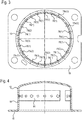
- In der vorbestimmten Orientierung der Anzünderhülse definieren die Überströmöffnungen in Umfangsrichtung vorteilhaft einen maximalen Winkelbereich, der sich zu beiden Seiten einer Verbindungslinie zwischen der Mittelachse der Anzünderhülse und dem von der Mittelachse maximal entfernten Abschnitt des Filters erstreckt. Dadurch wird der Filter bestmöglich geschont.
- Eine Auslegung der Überströmöffnungen, gemäß der der Winkelbereich Bereiche einschließt, in denen ein nicht durch Bauteile des Gasgenerators blockierter Abstand zum Filter maximal ist, ermöglicht eine optimale "Ausbeute" der aus den Überströmöffnungen austretenden Anzündstrahlen im Sinne einer maximalen Wirklänge. Der Treibstoff in der Brennkammer ist dabei nicht als Bauteil des Gasgenerators zu verstehen; im Gegenteil: es soll möglichst viel Treibstoff zwischen der Anzünderhülse und dem Filter von den Anzündstrahlen der abbrennenden Verstärkerladung erfasst werden.
- Der Winkelbereich kann auch ein Brennkammerbauteil, insbesondere eine Brennkammerhülse, einschließen, welches eine zweite Brennkammer umgibt, die selbst wiederum wenigstens teilweise von der ersten Brennkammer umgeben ist.
- In einer bevorzugten Ausführungsform ist der Winkelbereich stumpf und liegt vorzugsweise zwischen 90° und 135°, weiter vorzugsweise zwischen 100° und 120°, und beträgt weiter vorzugsweise etwa 110°.
- Im Hinblick auf eine Optimierung des Brennraums, der die Anzünderhülse umgibt, ist eine Gestaltung der Anzünderhülse vorteilhaft, bei der sich die Anzünderhülse in axialer Richtung zu einem Boden der Anzünderhülse hin radial verjüngt. In diesem Fall steht aufgrund der Verjüngung außerhalb der Anzünderhülse mehr Raum für den Treibstoff zur Verfügung.
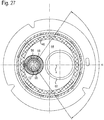
- Der Gasgenerator kann eine Anzünderhülse umfassen, die einen Anzünder und eine insbesondere mit einer Verstärkerladung gefüllte Anzünderkammer wenigstens teilweise umschließt und an eine einer ersten Aktivierungsstufe des Gasgenerators zugeordnete erste Brennkammer angrenzt. Der Gasgenerator umfasst ferner eine Brennkammerhülse, die eine mit Treibstoff gefüllte, einer zweiten Aktivierungsstufe des Gasgenerators zugeordnete zweite Brennkammer wenigstens teilweise umschließt. Beide Hülsen sind nebeneinander und vorzugsweise unterschiedlich versetzt zu einer Mittelachse des Gasgenerators angeordnet. Diese Anordnung führt zu einem äußerst kompakten und effizienten Aufbau eines zweistufigen Gasgenerators.
- Besonders effizient ist eine Ausgestaltung, bei der der Abstand zwischen den Mittelachsen der Anzünderhülse und der Brennkammerhülse zwischen 22,5 und 27,5 mm, vorzugsweise zwischen 23,5 und 26,5 mm liegt und weiter vorzugsweise etwa 25 mm beträgt.
- Bevorzugt liegt das Verhältnis des minimalen Innendurchmessers der Brennkammerhülse zum minimalen Innendurchmesser der Anzünderhülse zwischen 1,64 und 2,63, vorzugsweise zwischen 1,83 und 2,32. Weiter vorzugsweise beträgt dieses Verhältnis etwa 2,06.
- Eine optimale Abstimmung zwischen kompaktem Aufbau des zweistufigen Generators und effektiver Kühlung und Filterung des erzeugten Gases ergibt sich zum einen durch eine wenigstens teilweise radiale Begrenzung der ersten Brennkammer durch einen - bezogen auf eine Mittelachse des Gasgenerators - wenigstens teilweise umlaufenden Filter, wobei das Verhältnis des Innendurchmessers des Filters zum minimalen Innendurchmesser der Anzünderhülse zwischen 3,19 und 4,76, vorzugsweise zwischen 3,50 und 4,27 liegt und weiter vorzugsweise etwa 3,85 beträgt.
- Zum anderen wird bei einer solchen Filtergestaltung eine optimale Abstimmung bei einem Verhältnis des Innendurchmessers des Filters zum minimalen Innendurchmesser der Brennkammerhülse erreicht, das zwischen 1,66 und 2,11, vorzugsweise zwischen 1,76 und 1,99 liegt und weiter vorzugsweise etwa 1,87 beträgt.
- Gemäß einer effizienten Ausgestaltung des Gasgenerators liegt das Verhältnis des Außendurchmessers des Gasgenerators zum minimalen Innendurchmesser der Anzünderhülse zwischen 4,09 und 5,98, vorzugsweise zwischen 4,46 und 5,39, und beträgt weiter vorzugsweise etwa 4,89. Unter dem Außendurchmessers des Gasgenerators ist dabei der Außendurchmesser des äußersten Gasgeneratorbauteils zu verstehen, beispielsweise eines Diffusors, wobei ein sich seitlich (radial) erstreckender Flansch nicht berücksichtigt wird.
- Gemäß einer weiteren effizienten Ausgestaltung liegt das Verhältnis des Außendurchmessers des Gasgenerators zum minimalen Innendurchmesser der Brennkammerhülse zwischen 2,13 und 2,66, vorzugsweise zwischen 2,24 und 2,50, und beträgt weiter vorzugsweise etwa 2,38.
- Eine besonderer Aufbau sieht vor, dass der axiale Abstand einer offenen Seite der Anzünderhülse von einem Boden eines Verschlusskörpers des Gasgenerators ungleich dem axialen Abstand einer offenen Seite der Brennkammerhülse vom Boden des Verschlusskörpers ist, wobei der Abstand der Anzünderhülse vorzugsweise größer ist. Da die Anzünderhülse und die Brennkammerhülse unterschiedliche Durchmesser haben, wird dadurch die Verwendung von im Wesentlichen gleich aufgebauten Trägerbauteilen für beide Hülsen ermöglicht, die auf gleicher Höhe im Verschlusskörperboden eingebaut sein können und beide sowohl einen auf die Anzünderhülse abgestimmten ersten Aufnahmeabschnitt als auch einen axial hierzu versetzten, auf die Brennkammerhülse abgestimmten zweiten Aufnahmeabschnitt aufweisen.
- Im Hinblick auf den besonderen Mechanismus der zweiten Aktivierungsstufe, bei dem die aus der Brennkammerhülse herausführende Austrittsöffnung erst durch ein druckbedingtes Anheben der Brennkammerhülse entsteht, ist eine Halterung der Anzünderhülse und der Brennkammerhülse vorteilhaft, bei der die Anzünderhülse und die Brennkammerhülse auf einen ersten Anzünderträger bzw. auf einen zweiten Anzünderträger aufgesteckt sind, wobei die axiale Höhe des Kontaktbereichs zwischen der Anzünderhülse und dem ersten Anzünderträger größer ist als die axiale Höhe des Kontaktbereichs zwischen der Brennkammerhülse und dem zweiten Anzünderträger. Die Brennkammerhülse löst sich dann bereits nach einer geringen axialen Verschiebung vom zweiten Anzünderträger und gibt dadurch die gewünschte Austrittsöffnung frei. Bei der Anzünderhülse kann zwar auch eine axiale Verschiebung auftreten, eine Freigabe einer (zusätzlichen) Austrittsöffnung ist aber nicht vorgesehen.
- Dementsprechend ist eine bevorzugte Ausführungsform des Gasgenerators so ausgelegt, dass sowohl die Anzünderhülse durch den beim Abbrand der Verstärkerladung entstehenden Druck als auch die Brennkammerhülse durch den beim Abbrand des Treibstoffs entstehenden Druck angehoben werden, vorzugsweise in Richtung eines Deckenabschnitts eines Diffusors des Gasgenerators. Durch das Anheben der Brennkammerhülse wird eine Austrittsöffnung freigegeben, vorzugsweise in Form eines Austrittspalts, die aus der Brennkammerhülse herausführt, wogegen durch das Anheben der Anzünderhülse keine Austrittsöffnung freigegeben wird. Letzteres ist nicht erwünscht, da in der Anzünderhülse bereits vorteilhaft positionierte Überströmöffnungen vorhanden sind, die spätestens beim Abbrand der Verstärkerladung freigegeben werden.
- Vorzugsweise ist der Diffusor so ausgelegt, dass ein Deckenabschnitt die Bewegung der Anzünderhülse und die Bewegung der Brennkammerhülse begrenzt.
- Der Gasgenerator kann einen Filter umfassen und ein eine Brennkammer wenigstens teilweise umschließendes Brennkammerbauteil, insbesondere einer Brennkammerhülse. Der Filter weist einen kritischen Filterabschnitt auf, der dem Brennkammerbauteil näher als die restlichen Filterbereiche kommt. Der kritische Filterabschnitt weist im Vergleich zu Bereichen des Filters, die an den kritischen Filterabschnitt angrenzen, eine verringerte Dicke auf. Insbesondere ist zwischen dem Brennkammerbauteil und dem kritischen Filterabschnitt ein Spalt gebildet. Diese Maßnahme stellt einen Überzündschutz dar. Es muss sichergestellt sein, dass der Treibstoff der zweiten Aktivierungsstufe während und gegebenenfalls nach dem Abbrand des Treibstoffs der ersten Aktivierungsstufe nicht selbsttätig (thermisch) gezündet wird. Dabei ist ein Wärmeeintrag auf den Treibstoff der zweiten Aktivierungsstufe durch das Abbrennen des Treibstoffs der ersten Aktivierungsstufe selbst nicht unbedingt kritisch. Allerdings könnte eine Aufheizung des Filters und speziell die danach (verzögernd wirkende) Wärmerückstrahlung des aufgeheizten Filters negative Auswirkungen haben, speziell im Bereich nahe der Brennkammer der zweiten Aktivierungsstufe. Die Verjüngung des kritischen Filterabschnitts schafft deshalb vorsorglich einen wärmeisolierenden Abstand (Luftspalt) zwischen dem Filter und dem Brennkammerbauteil.
- Vorzugsweise ist das Material, aus dem der Filter gebildet ist, im kritischen Filterabschnitt höher verdichtet als in den angrenzenden Bereichen. Der kritische Filterabschnitt kann in diesem Fall einfach durch eine räumlich begrenzte Komprimierung des Filters hergestellt werden, ohne dass Material abgetragen werden muss.
- Zur weiteren Verbesserung kann das Brennkammerbauteil wenigstens in dem Bereich, der dem kritischen Filterabschnitt gegenüberliegt, eine erhöhte Materialdicke aufweisen. Die Kombination der Materialverdickung des Brennkammerbauteils mit der gegenüberliegenden Filterverjüngung ergibt einen optimalen Überzündschutz.
- Gemäß einer bevorzugten Anordnung erstreckt sich der Filter entlang einer umlaufenden Wand des Gasgenerators, die eine Kammer des Gasgenerators umgibt, in welcher das Brennkammerbauteil angeordnet ist.
- Im Falle eines Brennkammerbauteils, das sich über eine größere axiale Höhe als der Filter erstreckt, ist es ausreichend, wenn das Brennkammerbauteil im Wesentlichen nur in dem axialen Bereich eine erhöhte Materialdicke aufweist, in dem sich auch der Filter erstreckt. Somit können Materialkosten und Gewicht eingespart werden.
- Gemäß einer effizienten Ausgestaltung liegt das Verhältnis der minimalen Dicke des kritischen Filterabschnitts zur Dicke der angrenzenden Bereiche des Filters zwischen 0,43 und 0,93, vorzugsweise zwischen 0,53 und 0,78, und beträgt weiter vorzugsweise etwa 0,65.
- Gemäß einer weiteren effizienten Ausgestaltung des Überzündschutzes liegt das Verhältnis der minimalen Dicke des kritischen Filterabschnitts zur maximalen Breite des Spalts zwischen 1,17 und 2,85, vorzugsweise zwischen 1,50 und 2,23, und beträgt weiter vorzugsweise etwa 1,83.
- Eine besondere Gestaltung und Anordnung des Filters sieht vor, dass der Gasgenerator auf einer ersten axialen Stirnseite durch einen Diffusor mit einer im Wesentlichen axial verlaufenden Umfangswand geschlossen ist, wobei sich der Filter in axialer Richtung über die Umfangswand hinaus erstreckt.
- Der Gasgenerator kann eine umlaufende Wand umfassen, die insbesondere eine Brennkammer umgibt, und einen Filter, der wenigstens teilweise entlang der Wand verläuft. Die Wand weist wenigstens einen Stützabschnitt auf. Der Stützabschnitt bildet eine axiale Halterung für den Filter und ist vorzugsweise einstückig mit der Wand ausgeführt. Vorteil dieser Wandhalterung für den Filter ist, dass sich der Filter im Inneren des Gasgenerators nicht unnötig über die gesamte Höhe erstrecken muss. Dadurch kann Filtermaterial eingespart werden, und es steht mehr Raum für Treibstoff in der vom Filter dann nur teilweise umgebenen Brennkammer zur Verfügung. Auf ein ansonsten notwendiges separates Stützelement kann verzichtet werden.
- Es kann entweder nur ein Stützabschnitt vorgesehen sein, der durch eine vollständig umlaufende, vorzugsweise eingeprägte Sicke gebildet ist, oder es können mehrere Stützabschnitte durch vorzugsweise eingeprägte Sicken gebildet sein. Gemäß der letzteren Alternative können die Sicken in Umfangsrichtung voneinander beabstandet sein.
- Gemäß einer bevorzugten Ausführungsform ist der Gasgenerator auf einer axialen Stirnseite durch einen Verschlusskörper geschlossen, und der bzw. die Stützabschnitte sind in einem hochgezogenen Rand des Verschlusskörpers gebildet.
- Eine vorteilhafte Ausgestaltung sieht vor, dass sich der Filter nur mit einem radial äußeren Bereich auf dem bzw. den Stützabschnitten abstützt. Im Falle einer eingeprägten Sicke muss sich diese also nicht über die gesamte Dicke des ringförmigen Filters nach innen erstrecken.
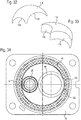
- Der Gasgenerator kann eine mit einem Treibstoff gefüllte erste Brennkammer umfassen, die einer ersten Aktivierungsstufe des Gasgenerators zugeordnet ist und auf einer Seite durch einen Deckel, insbesondere einen Diffusor geschlossen ist. Zwischen dem Treibstoff und dem Deckel ist ein erster Füllkörper angeordnet. Der erste Füllkörper weist wenigstens eine, vorzugsweise kreisförmige, Aussparung auf. In die Aussparung ragt eine Hülse hinein, insbesondere eine Anzünderhülse, die der ersten Aktivierungsstufe des Gasgenerators zugeordnet ist, oder eine Brennkammerhülse, die einer zweiten Aktivierungsstufe des Gasgenerators zugeordnet ist. Ein so gestalteter Füllkörper hat, abgesehen von der Erfüllung seines Hauptzwecks, mehrere Vorteile. So unterstützt er die Stabilität der in die Aussparung hineinragenden Hülse hinsichtlich einem unerwünschten Verschieben oder Kippen in seitlicher Richtung. Außerdem erlaubt die besondere Ausgestaltung des Füllkörpers eine in axialer Richtung äußerst kompakte Bauform, da die Hülse in den Füllkörper hineinragt, sodass der Raum zwischen der Hülse und dem Deckel minimiert werden kann.
- Insbesondere bei einem zweistufigen Gasgenerator weist der erste Füllkörper gemäß einer bevorzugten Ausführungsform zwei Aussparungen unterschiedlicher Größe auf, wobei in die kleinere Aussparung vorzugsweise die Anzünderhülse und in die größere Aussparung vorzugsweise die Brennkammerhülse hineinragt.
- Eine effiziente Ausgestaltung sieht vor, dass das Verhältnis des Durchmessers der größeren Aussparung zum Durchmesser der kleineren Aussparung zwischen 1,52 und 2,25, vorzugsweise zwischen 1,67 und 2,03 liegt und weiter vorzugsweise etwa 1,84 beträgt.
- Die Herstellung des ersten Füllkörpers kann vereinfacht werden, indem der erste Füllkörper wenigstens zweiteilig ausgeführt wird. Ein weiterer Vorteil der zweiteiligen Ausführung besteht darin, dass beim Einbau des Füllkörpers größere Toleranzen ausgeglichen werden können als bei einer einstückige Ausführung des Füllkörpers.
- Besonders zweckmäßig ist in diesem Fall ein Design, bei dem die zwei Teilkörper des ersten Füllkörpers jeweils die Form eines Doppelhalbmonds aufweisen. Die Füllkörper können dann identische Formen haben und symmetrisch zueinander angeordnet werden.
- Das bevorzugte Material für den Füllkörper ist Silikon, das einerseits nachgiebig ist, um den Treibstoff zur Vermeidung von Geräuschen unter Druck festzuhalten. Andererseits reagiert das Silikon im Aktivierungsfall des Gasgenerators nicht in unerwünschter Weise mit dem Treibstoff oder mit Bauteilen des Gasgenerators.
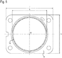
- Der Gasgenerator kann einen bezogen auf eine Mittelachse des Gasgenerators radial abstehenden Generatorflansch umfassen zur Befestigung des Gasgenerators an einem Generatorträger. Der Generatorflansch hat im Wesentlichen die Form eines Rechtecks. Die rechteckige Gestaltung des Generatorflanschs ermöglicht eine platzsparende Gestaltung des Generatorträgers und des den Gasgenerator umgebenden Bauraums, insbesondere dann, wenn der Flansch nur geringfügig breiter als der Außendurchmesser des Außengehäuses des Gasgenerators ist. Unter einer im Wesentlichen rechteckigen Form ist dabei nicht unbedingt ein perfektes Rechteck zu verstehen; grundsätzlich rechteckige Formen mit abgerundeten Ecken, randseitigen Ausnehmungen, etc. sollen mit umfasst sein.
- Bei einem bevorzugten Design ist vorgesehen, dass der Gasgenerator ein Außengehäuse mit einem vorzugsweise kreisförmigen Querschnitt hat, dessen Mittelachse durch den Mittelpunkt des Generatorflanschs verläuft.
- Bezüglich der Dimensionen des Generatorflanschs hat sich für die Anbringung des Gasgenerators am Generatorträger ein Verhältnis von Länge zu Breite des Rechtecks zwischen 1,12 und 1,31, vorzugsweise zwischen 1,16 und 1,27 als vorteilhaft herausgestellt. Weiter vorzugsweise beträgt dieses Verhältnis etwa 1,21.
- Ebenfalls bevorzugt wird ein Verhältnis der Länge des Rechtecks zum Außendurchmesser des Außengehäuses, das zwischen 1,24 und 1,48, vorzugsweise zwischen 1,30 und 1,42 liegt und weiter vorzugsweise etwa 1,36 beträgt.
- Bezüglich der Breite des Generatorflanschs wird ein Verhältnis der Breite des Rechtecks zum Außendurchmesser des Außengehäuses bevorzugt, das zwischen 1,01 und 1,23, vorzugsweise zwischen 1,06 und 1,17 liegt und weiter vorzugsweise etwa 1,12 beträgt.
- Der Gasgenerator kann eine Anzündereinheit umfassen, die eine Markierung aufweist. Die Markierung erleichtert einen Einbau der Anzündereinheit, bei dem diese eine vorbestimmte Orientierung hat. Dies ist insbesondere vor dem Hintergrund vorteilhaft, dass die elektrischen Anschlusspins des Anzünders orientiert im Gasgenerator verbaut werden müssen, um später ein korrektes Aufstecken des Gegensteckers in die Schnittstelle/Kavität des Anzünderträgers der Anzündereinheit sicherzustellen. Das Werkzeug, welches beim Zusammenbau des Gasgenerators die vormontierte Anzündeinheit dem Gasgeneratorbauteil orientiert zuführt, in das die Anzündereinheit eingesetzt wird, muss hierzu nicht in die sensible Schnittstelle des Anzünderträgers "hineinfahren". Somit werden die empfindlichen Anschlusspins des Anzünders keinem unnötigen Werkzeugkontakt ausgesetzt.
- Als Markierung bietet sich insbesondere eine Einfräsung an.
- Eine vereinfachte Handhabung ergibt sich dadurch, dass die Anzündereinheit eine vormontierte Einheit mit einem Anzünderträger und einem darin gehaltenen Anzünder ist, die vorzugsweise in eine Bodenöffnung eines Verschlusskörpers des Gasgenerators einsetzbar ist.
- Der Gasgenerator kann einen Diffusor umfassen, der mit einem Verschlusskörper ein vorzugsweise im Wesentlichen rotationssymmetrisches Außengehäuse des Gasgenerators bildet, wobei die Wanddicke des Verschlusskörpers wenigstens abschnittsweise größer als die des Diffusors ist. Dieser Aspekt beruht auf der Erkenntnis, dass eine höhere Wanddicke des Verschlusskörpers für die Aufnahme einer oder mehrerer Anzündereinheiten von Vorteil ist, während eine vergleichsweise dünne Wandstärke des Diffusors ein erwünschtes Ausbauchen des Diffusors im Aktivierungsfall ermöglicht.
- Dementsprechend ist bei einer bevorzugten Gestaltung vorgesehen, dass der Verschlusskörper einen im Wesentlichen ebenen Boden aufweist, in dem vorzugsweise wenigstens eine Öffnung zur Aufnahme eines Anzünderträgers gebildet ist. Wenigstens der Boden hat eine größere Wanddicke als der Diffusor.
- Der Gasgenerator kann ein eine Brennkammer wenigstens teilweise umschließendes Brennkammerbauteil umfassen, insbesondere eine Brennkammerhülse, und einen Diffusor mit einem Deckenabschnitt. Bezogen auf eine Mittelachse des Diffusors variiert der axiale Abstand zwischen dem Brennkammerbauteil und dem Deckenabschnitt. Bei einer symmetrischen Wölbung des Deckenabschnitts und einer bezüglich der Mittelachse senkrechten Anordnung des dem Deckenabschnitt gegenüberliegenden Abschnitts des Brennkammerbauteils entspricht dies einer bezüglich der Mittelachse versetzten Anordnung des Brennkammerbauteils.
- Vorzugsweise berührt das Brennkammerbauteil den Deckenabschnitt des Diffusors in einem nicht aktivierten Zustand des Gasgenerators wenigstens an einer Stelle. Aufgrund des an den anderen Stellen vorhandenen Abstands zwischen dem Brennkammerbauteil und dem Deckenabschnitt wird dadurch ein Kippen des Brennkammerbauteils (Brennkammerhülse) ermöglicht, wie es gemäß der besonderen Funktionsweise der zweiten Aktivierungsstufe des Gasgenerators vorgesehen ist.
- Das Kippen wird begünstigt durch eine Ausgestaltung, bei der der axiale Abstand zwischen dem Brennkammerbauteil und dem Deckenabschnitt des Diffusors an der Mittelachse des Diffusors am größten ist und sich mit zunehmendem radialem Abstand von der Mittelachse vorzugsweise stetig verringert.
- Gemäß einer bevorzugten Ausführungsform liegt der maximale Abstand zwischen dem Brennkammerbauteil und dem Deckenabschnitt des Diffusors zwischen 2,3 und 3,7 mm, vorzugsweise zwischen 2,7 und 3,3 mm, und beträgt weiter vorzugsweise etwa 3,0 mm.
- Ebenso kann eine versetzt zur Mittelachse des Diffusors angeordnete Anzünderhülse vorgesehen sein, deren axialer Abstand zum Deckenabschnitt des Diffusors in ähnlicher Weise variiert, insbesondere indem sich der axiale Abstand der Anzünderhülse vom Deckenabschnitt des Diffusors mit zunehmendem radialem Abstand von der Mittelachse des Diffusors vorzugsweise stetig verringert.
- Gemäß einer bevorzugten Ausführungsform liegt der maximale Abstand zwischen der Anzünderhülse und dem Deckenabschnitt des Diffusors zwischen 2,1 und 3,5 mm, vorzugsweise zwischen 2,5 und 3,1 mm, und beträgt weiter vorzugsweise etwa 2,8 mm.
- Der Gasgenerator kann eine erste Brennkammer umfassen, die einer ersten Aktivierungsstufe des Gasgenerators zugeordnet ist, und eine zweite Brennkammer, die einer zweiten Aktivierungsstufe des Gasgenerators zugeordnet ist. Die zweite Brennkammer ist wenigstens teilweise von der ersten Brennkammer umgeben und weist ein kleineres Volumen als die erste Brennkammer auf. Diese Anordnung und Dimensionierung der Brennkammern ermöglicht einen auch in radialer Richtung äußerst kompakten Aufbau eines zweistufigen Gasgenerators.
- Eine effiziente Ausgestaltung sieht vor, dass das Verhältnis des Volumens der ersten Brennkammer zum Volumen der zweiten Brennkammer zwischen 2,07 und 3,78, vorzugsweise zwischen 2,41 und 3,21 liegt und weiter vorzugsweise etwa 2,82 beträgt.
- Eine weitere effiziente Ausgestaltung sieht vor, dass das Verhältnis des Volumens der ersten Brennkammer zum Volumen einer von der ersten Brennkammer wenigstens teilweise umgebenden Anzünderhülse zwischen 9,00 und 35,0, vorzugsweise zwischen 11,6 und 22,0 liegt und weiter vorzugsweise etwa 15,5 beträgt.
- Die obigen Verhältnisse sind insbesondere bei einem Gasgeneratordesign vorteilhaft, bei dem das Verhältnis des Außendurchmessers eines Außengehäuses des Gasgenerators zur Höhe des Außengehäuses zwischen 1,38 und 1,78 liegt und weiter vorzugsweise etwa 1,57 beträgt.
- Ein solcher Gasgenerator, dessen Bauhöhe, insbesondere die axiale Höhe eines Außengehäuses des Gasgenerators, zwischen 30 und 50 mm liegt und vorzugsweise etwa 40 mm beträgt, ist besonders geeignet für ein Fahrergassackmodul in einem Fahrzeug, mit einem Gassack, der ein Volumen von 40 bis 60 Liter aufweist.
- Eine andere effiziente Ausgestaltung sieht vor, dass das Verhältnis des Volumens der ersten Brennkammer zum Volumen der zweiten Brennkammer zwischen 2,34 und 3,27, vorzugsweise zwischen 2,54 und 3,00 liegt und weiter vorzugsweise etwa 2,76 beträgt.
- Eine weitere effiziente Ausgestaltung sieht vor, dass das Verhältnis des Volumens der ersten Brennkammer zum Volumen einer von der ersten Brennkammer wenigstens teilweise umgebenden Anzünderhülse zwischen 13,5 und 31,0, vorzugsweise zwischen 16,0 und 24,0 liegt und weiter vorzugsweise etwa 19,3 beträgt.
- Die zuletzt angegebenen Verhältnisse sind insbesondere bei einem Gasgeneratordesign vorteilhaft, bei dem das Verhältnis des Außendurchmessers eines Außengehäuses des Gasgenerators zur Höhe des Außengehäuses zwischen 0,94 und 1,16 liegt und weiter vorzugsweise etwa 1,05 beträgt.
- Ein solcher Gasgenerator, dessen Bauhöhe, insbesondere die axiale Höhe eines Außengehäuses des Gasgenerators, zwischen 50 und 70 mm liegt und vorzugsweise etwa 60 mm beträgt, ist besonders geeignet für ein Beifahrergassackmodul in einem Fahrzeug, mit einem Gassack, der ein Volumen von 60 bis 135 Liter aufweist.
Claims (13)
- Gasgenerator für eine Schutzeinrichtung in einem Fahrzeug mit einer Brennkammerhülse (60), die eine mit Treibstoff gefüllte Brennkammer (56) wenigstens teilweise umschließt, und die Brennkammerhülse (60) so ausgelegt ist, dass sie durch einen beim Abbrand des Treibstoffs entstehenden Druck ihre Lage und/oder Form so ändert, dass durch eine Austrittsöffnung (112), die aus der Brennkammer (56) herausführt, ein beim Abbrand des Treibstoffs entstehendes Abbrandgas freigegeben wird, dadurch gekennzeichnet, dass die Brennkammerhülse (60) auf ein Trägerbauteil des Gasgenerators aufgesteckt ist, wobei die Austrittsöffnung (112) dadurch entsteht, dass sich die Brennkammerhülse (60) wenigstens teilweise von dem Trägerbauteil löst.
- Gasgenerator nach zumindest einem der vorhergehenden Ansprüche, dadurch gekennzeichnet, dass die Brennkammerhülse (60) auf einen Treibstoffkanister (58) aufgeschoben ist, der mit Treibstoff gefüllt ist, und einen Treibstoffkanisterboden (66) mit einem oder mehreren Löchern (106) aufweist, durch die das Abbrandgas zur Austrittsöffnung (112) gelangen kann, wobei vorzugsweise das bzw. die Löcher (106) im Treibstoffkanisterboden (66) erst durch den beim Abbrand des Treibstoffs entstehenden Druck und ein dadurch bedingtes Aufreißen des Treibstoffkanisterbodens (66) gebildet wird bzw. werden.
- Gasgenerator nach zumindest einem der voranstehenden Ansprüche, dadurch gekennzeichnet, dass die Brennkammerhülse (60) durch den Druck auf einen Deckenabschnitt (14) eines Diffusors (10) des Gasgenerators zu bewegbar ist, wobei die Bewegung vorzugsweise durch den Deckenabschnitt (14) begrenzt ist.
- Gasgenerator nach Anspruch 3, dadurch gekennzeichnet, dass sich die Brennkammerhülse (60) teilweise am Deckenabschnitt (14) des Diffusors (10) abstützt, vorzugsweise bereits vor einer Aktivierung des Gasgenerators, und durch den Druck ein Kippen und/oder eine ungleichmäßige Verformung der Brennkammerhülse (60) hervorgerufen wird.
- Gasgenerator nach zumindest einem der vorhergehenden Ansprüche, dadurch gekennzeichnet, dass der Gasgenerator eine Anzünderhülse (38) hat, die einen Anzünder (34) und eine insbesondere mit einer Verstärkerladung gefüllte Anzünderkammer (42) wenigstens teilweise umschließt und an eine mit Treibstoff gefüllte erste Brennkammer (44) angrenzt, wobei die Anzünderhülse (38) bezogen auf eine Mittelachse B der Anzünderhülse (38) in Umfangsrichtung ungleichmäßig verteilte Überströmöffnungen (98) aufweist.
- Gasgenerator nach Anspruch 5, dadurch gekennzeichnet, dass die Überströmöffnungen (98) in Umfangsrichtung einen maximalen Winkelbereich α definieren, der sich zu beiden Seiten einer Verbindungslinie x zwischen der Mittelachse B der Anzünderhülse (38) und dem von der Mittelachse B maximal entfernten Abschnitt des Filters (46) erstreckt, wobei der Winkelbereich α insbesondere stumpf ist und vorzugsweise zwischen 90° und 135°, weiter vorzugsweise zwischen 100° und 120° liegt und weiter vorzugsweise etwa 110° beträgt.
- Gasgenerator nach Anspruch 6, dadurch gekennzeichnet, dass der Winkelbereich α Bereiche einschließt, in denen ein nicht durch Bauteile des Gasgenerators blockierter Abstand zum Filter (46) maximal ist.
- Gasgenerator nach mindestens einem der Ansprüche 6 bis 7, dadurch gekennzeichnet, dass der Winkelbereich α ein in der ersten Brennkammer angeordnetes Brennkammerbauteil, insbesondere die Brennkammerhülse (60), einschließt, welches eine/die zweite Brennkammer (56) umgibt, die selbst wiederum wenigstens teilweise von der ersten Brennkammer (44) umgeben ist.
- Gasgenerator nach zumindest einem der vorhergehenden Ansprüche 5 bis 8, dadurch gekennzeichnet, dass sowohl die Anzünderhülse (38) durch den beim Abbrand der Verstärkerladung entstehenden Druck als auch die Brennkammerhülse (60) durch den beim Abbrand des Treibstoffs entstehenden Druck angehoben werden, wobei durch das Anheben der Anzünderhülse (38) keine Austrittsöffnung freigegeben wird.
- Gasgenerator nach zumindest einem der vorhergehenden Ansprüche 5 bis 9, dadurch gekennzeichnet, dass die erste Brennkammer (44) einer ersten Aktivierungsstufe des Gasgenerators zugeordnet ist und auf einer Seite durch einen Deckel geschlossen ist, wobei zwischen dem Treibstoff und dem Deckel ein erster Füllkörper (82) angeordnet ist, wobei der erste Füllkörper (82) wenigstens eine Aussparung (116, 118) aufweist, in die eine Hülse, insbesondere die Anzünderhülse (38), die der ersten Aktivierungsstufe des Gasgenerators zugeordnet ist, oder die Brennkammerhülse (60), die einer zweiten Aktivierungsstufe des Gasgenerators zugeordnet ist, hineinragt, wobei der erste Füllkörper (82) zwei Aussparungen (116, 118) unterschiedlicher Größe aufweist.
- Gasgenerator nach Anspruch 10, dadurch gekennzeichnet, dass der erste Füllkörper (82) wenigstens zweiteilig ausgeführt ist, wobei vorzugsweise die zwei Teilkörper (114) jeweils die Form eines Doppelhalbmonds aufweisen.
- Gassackmodul für ein Fahrzeug, mit einem Gassack, der ein Volumen von 40 bis 60 Liter aufweist, gekennzeichnet durch einen Gasgenerator nach einem der Ansprüche 1 bis 11.
- Gassackmodul für ein Fahrzeug, mit einem Gassack, der ein Volumen von 60 bis 135 Liter aufweist, gekennzeichnet durch einen Gasgenerator nach einem der Ansprüche 1 bis 11.
Applications Claiming Priority (3)
| Application Number | Priority Date | Filing Date | Title |
|---|---|---|---|
| DE202010014286U DE202010014286U1 (de) | 2010-10-15 | 2010-10-15 | Gasgenerator und Gassackmodul |
| PCT/DE2011/001820 WO2012062262A2 (de) | 2010-10-15 | 2011-09-27 | Gasgenerator und gassackmodul |
| EP11813864.3A EP2627541B1 (de) | 2010-10-15 | 2011-09-27 | Gasgenerator und gassackmodul |
Related Parent Applications (1)
| Application Number | Title | Priority Date | Filing Date |
|---|---|---|---|
| EP11813864.3A Division EP2627541B1 (de) | 2010-10-15 | 2011-09-27 | Gasgenerator und gassackmodul |
Publications (2)
| Publication Number | Publication Date |
|---|---|
| EP3444149A1 EP3444149A1 (de) | 2019-02-20 |
| EP3444149B1 true EP3444149B1 (de) | 2021-11-10 |
Family
ID=45557829
Family Applications (5)
| Application Number | Title | Priority Date | Filing Date |
|---|---|---|---|
| EP18182140.6A Active EP3421302B1 (de) | 2010-10-15 | 2011-09-27 | Gasgenerator |
| EP18182137.2A Active EP3444149B1 (de) | 2010-10-15 | 2011-09-27 | Gasgenerator und gassackmodul |
| EP11813864.3A Active EP2627541B1 (de) | 2010-10-15 | 2011-09-27 | Gasgenerator und gassackmodul |
| EP18182143.0A Active EP3473501B1 (de) | 2010-10-15 | 2011-09-27 | Gasgenerator und gassackmodul |
| EP18182139.8A Active EP3446933B1 (de) | 2010-10-15 | 2011-09-27 | Gasgenerator und gassackmodul |
Family Applications Before (1)
| Application Number | Title | Priority Date | Filing Date |
|---|---|---|---|
| EP18182140.6A Active EP3421302B1 (de) | 2010-10-15 | 2011-09-27 | Gasgenerator |
Family Applications After (3)
| Application Number | Title | Priority Date | Filing Date |
|---|---|---|---|
| EP11813864.3A Active EP2627541B1 (de) | 2010-10-15 | 2011-09-27 | Gasgenerator und gassackmodul |
| EP18182143.0A Active EP3473501B1 (de) | 2010-10-15 | 2011-09-27 | Gasgenerator und gassackmodul |
| EP18182139.8A Active EP3446933B1 (de) | 2010-10-15 | 2011-09-27 | Gasgenerator und gassackmodul |
Country Status (5)
| Country | Link |
|---|---|
| US (5) | US9452729B2 (de) |
| EP (5) | EP3421302B1 (de) |
| DE (2) | DE202010014286U1 (de) |
| FR (1) | FR2966232B1 (de) |
| WO (1) | WO2012062262A2 (de) |
Families Citing this family (24)
| Publication number | Priority date | Publication date | Assignee | Title |
|---|---|---|---|---|
| DE202010014286U1 (de) * | 2010-10-15 | 2012-01-30 | Trw Airbag Systems Gmbh | Gasgenerator und Gassackmodul |
| US8820783B1 (en) * | 2012-01-08 | 2014-09-02 | Tk Holdings Inc. | Gas generating system |
| DE102013005153A1 (de) | 2013-03-26 | 2014-10-02 | Trw Airbag Systems Gmbh | GASGENERATOR, lNSBESONDERE FÜR ElN lNSASSENRÜCKHALTESYSTEM ElNES KRAFTFAHRZEUGS, GASSACKMODUL, FAHRZEUGSlCHERHElTSSYSTEM UND VERFAHREN ZUR HERSTELLUNG EINES GASENERATORS |
| US9776592B2 (en) * | 2013-08-22 | 2017-10-03 | Autoliv Asp, Inc. | Double swage airbag inflator vessel and methods for manufacture thereof |
| US9643565B1 (en) * | 2014-03-26 | 2017-05-09 | Tk Holdings Inc. | Secondary chamber combustion control mechanism |
| US9216710B2 (en) * | 2014-04-23 | 2015-12-22 | Autoliv Asp, Inc. | Airbag inflator mounting apparatus, methods, and systems |
| DE102014010942A1 (de) * | 2014-07-28 | 2016-01-28 | Trw Airbag Systems Gmbh | Gasgenerator für ein Fahrzeuginsassensicherheitssystem, Gassackmodul und Fahrzeuginsassensicherheitssystem mit einem solchen Gasgenerator sowie Herstellungsverfahren |
| US9682679B2 (en) | 2014-08-08 | 2017-06-20 | Autoliv Asp, Inc. | Airbag inflator retainers and related methods and systems |
| US10281248B2 (en) * | 2015-11-11 | 2019-05-07 | Northrop Grumman Innovation Systems, Inc. | Gas generators, launch tube assemblies including gas generators, and related systems and methods |
| WO2017146158A1 (ja) * | 2016-02-23 | 2017-08-31 | 日本化薬株式会社 | ガス発生器 |
| JP6681772B2 (ja) * | 2016-04-06 | 2020-04-15 | 日本化薬株式会社 | ガス発生器 |
| DE102016213002B4 (de) * | 2016-07-15 | 2019-02-14 | Joyson Safety Systems Germany Gmbh | Gasgenerator für ein Gassackmodul eines Fahrzeuginsassen-Rückhaltesystems und Verfahren zum Herstellen eines Gasgenerators |
| JP6714495B2 (ja) * | 2016-11-10 | 2020-06-24 | 株式会社ダイセル | ガス発生器 |
| JP6910828B2 (ja) * | 2017-04-03 | 2021-07-28 | 日本化薬株式会社 | ガス発生器 |
| JP2019069677A (ja) | 2017-10-06 | 2019-05-09 | 株式会社ダイセル | ガス発生器 |
| JP7030486B2 (ja) * | 2017-11-20 | 2022-03-07 | 株式会社ダイセル | ガス発生器 |
| JP7233855B2 (ja) * | 2018-05-22 | 2023-03-07 | 株式会社ダイセル | ガス発生器 |
| KR102622079B1 (ko) * | 2018-05-29 | 2024-01-09 | 주식회사 다이셀 | 가스 발생기 |
| DE202018104422U1 (de) * | 2018-07-31 | 2019-11-04 | Trw Airbag Systems Gmbh | Gasgenerator, Modul und Fahrzeugsicherheitssystem mit einem Gasgenerator |
| KR102579301B1 (ko) * | 2018-12-11 | 2023-09-15 | 현대자동차주식회사 | 차량의 동승석 에어백 인플레이터 및 시스템 |
| KR102647198B1 (ko) | 2018-12-14 | 2024-03-12 | 현대자동차주식회사 | 에어백용 인플레이터 제어방법 |
| JP7130076B2 (ja) * | 2021-02-26 | 2022-09-02 | 日本化薬株式会社 | ガス発生器 |
| US12214741B2 (en) * | 2021-03-19 | 2025-02-04 | Nippon Kayaku Kabushiki Kaisha | Gas generator |
| JP7795979B2 (ja) * | 2022-06-28 | 2026-01-08 | 株式会社ダイセル | ガス発生器及びガス発生器の製造方法 |
Citations (1)
| Publication number | Priority date | Publication date | Assignee | Title |
|---|---|---|---|---|
| EP3421302A1 (de) * | 2010-10-15 | 2019-01-02 | TRW Airbag Systems GmbH | Gasgenerator |
Family Cites Families (96)
| Publication number | Priority date | Publication date | Assignee | Title |
|---|---|---|---|---|
| DE1136330B (de) | 1960-07-08 | 1962-09-13 | Wolfen Filmfab Veb | Verfahren zur Herstellung von N-Phenyl-N'-cycloalkyl-p-phenylendiaminen |
| FR2269057B1 (de) | 1974-04-29 | 1976-12-17 | Poudres & Explosifs Ste Nale | |
| DE3831641A1 (de) | 1988-08-09 | 1990-02-15 | Daimler Benz Ag | Gasgenerator zum fuellen einer gaskissen-rueckhalteeinrichtung |
| DE3924500C1 (de) * | 1989-07-25 | 1990-12-20 | Bayern-Chemie Gesellschaft Fuer Flugchemische Antriebe Mbh, 8261 Aschau, De | |
| DE4141620C2 (de) * | 1990-12-18 | 1996-04-11 | Trw Inc | Startvorrichtungs- oder Initiatoranordnung für eine Airbagaufblasvorrichtung |
| US5199741A (en) * | 1990-12-18 | 1993-04-06 | Trw Inc. | Method of assembling an inflator |
| US5332256A (en) * | 1992-02-24 | 1994-07-26 | Morton International, Inc. | Continuous circumference diffuser reaction canister |
| US5611566A (en) * | 1992-08-20 | 1997-03-18 | Temic Bayern-Chemie Airbag Gmbh | Gas generator for a safety system for protecting occupants in motor vehicles |
| JPH06344854A (ja) | 1993-06-08 | 1994-12-20 | Takata Kk | エアバッグ装置のインフレータ |
| US5366239A (en) | 1993-09-27 | 1994-11-22 | Trw Inc. | Air bag inflator assembly |
| DE4435319A1 (de) * | 1994-10-01 | 1996-04-04 | Temic Bayern Chem Airbag Gmbh | Anzündeinheit für einen Gasgenerator eines passiven Rückhaltesystems |
| US5613705A (en) * | 1995-03-24 | 1997-03-25 | Morton International, Inc. | Airbag inflator having a housing protected from high-temperature reactive generated gases |
| US5582427A (en) * | 1995-06-28 | 1996-12-10 | Morton International, Inc. | Dual-wall pyrotechnic air bag inflator with tortuous gas flow |
| DE19541584A1 (de) * | 1995-11-08 | 1997-05-15 | Temic Bayern Chem Airbag Gmbh | Anordnung zum mehrstufigen Zünden von Gasgeneratoren |
| US6234521B1 (en) * | 1996-04-08 | 2001-05-22 | Daicel Chemical Industries, Ltd. | Airbag inflator and an airbag apparatus |
| DE19617249C2 (de) * | 1996-04-30 | 1999-11-04 | Temic Bayern Chem Airbag Gmbh | Gasgenerator |
| DE19620758A1 (de) * | 1996-05-23 | 1997-11-27 | Temic Bayern Chem Airbag Gmbh | Gasgenerator |
| US5700973A (en) * | 1996-11-13 | 1997-12-23 | Automotive Systems Laboratory, Inc. | Gas inflator having aluminum bead filter |
| US6089598A (en) * | 1996-11-22 | 2000-07-18 | Autoliv Asp, Inc. | Pyrotechnic inflator with reduced extent filter and cartridge charges |
| US5752715A (en) * | 1997-02-14 | 1998-05-19 | Morton International, Inc. | Airbag module diffuser |
| DE19709597A1 (de) * | 1997-03-08 | 1998-09-17 | Temic Bayern Chem Airbag Gmbh | Vorrichtung zur Arretierung von Brennstoffgranulat in Brennkammern |
| US6547278B2 (en) * | 1997-03-08 | 2003-04-15 | Trw Airbag Systems Gmbh & Co. Kg | Gas generator for a safety arrangement |
| US6474684B1 (en) * | 1997-04-24 | 2002-11-05 | Talley Defense Systems, Inc. | Dual stage inflator |
| FR2763548B1 (fr) | 1997-05-23 | 1999-06-18 | Livbag Snc | Generateur pyrotechnique de gaz adaptatif a chambres tubulaires pour coussin de protection |
| FR2772909B1 (fr) * | 1997-12-22 | 2000-01-28 | Livbag Snc | Initiateur electro-pyrotechnique a trois connexions electriques |
| DE19757478A1 (de) * | 1997-12-23 | 1999-06-24 | Dynamit Nobel Ag | Pyrotechnischer Gasgenerator |
| US6206417B1 (en) * | 1998-05-08 | 2001-03-27 | Autoliv Asp, Inc. | Air bag inflator exit gas dispersion features |
| US6068294A (en) | 1998-05-26 | 2000-05-30 | Autoliv Asp, Inc. | Vertical seat locking retainer disk and tube combination |
| FR2780729B1 (fr) | 1998-07-06 | 2000-08-25 | Inst Francais Du Petrole | Derives zwitterioniques et application aux proprietes des suspensions aqueuses |
| JP3220443B2 (ja) * | 1998-11-30 | 2001-10-22 | ダイセル化学工業株式会社 | エアバッグ用ガス発生器及びエアバッグ装置 |
| US6929284B1 (en) * | 1999-02-05 | 2005-08-16 | Nippon Kayaku Kabushiki-Kaisha | Gas generator |
| ATE287279T1 (de) | 1999-02-16 | 2005-02-15 | Daicel Chem | Filter für einen mehrstufigen gasgenerator für einen airbag und airbagvorrichtung |
| US6701849B2 (en) * | 1999-03-05 | 2004-03-09 | Trw Inc. | Dual stage air bag inflator with secondary propellant cap |
| DE29915056U1 (de) * | 1999-08-27 | 2000-01-27 | TRW Airbag Systems GmbH & Co. KG, 84544 Aschau | Zündereinheit für einen Gasgenerator |
| JP4426079B2 (ja) * | 1999-09-27 | 2010-03-03 | ダイセル化学工業株式会社 | イニシエータ組立体 |
| EP1106445A1 (de) | 1999-12-10 | 2001-06-13 | ACTS-Advanced Car Technology Systems GmbH & Co.KG | In ein Innenverkleidungsteil für Kraftfahrzeuge integriertes Airbag-System |
| US6189927B1 (en) * | 1999-12-16 | 2001-02-20 | Autoliv Asp, Inc. | Adaptive output inflator |
| WO2001047752A1 (en) * | 1999-12-28 | 2001-07-05 | Nippon Koki Co., Ltd. | Dual inflator |
| US6299200B1 (en) * | 2000-07-18 | 2001-10-09 | Trw Vehicle Safety Systems Inc. | Side impact air bag module with shroud |
| DE60225248T2 (de) * | 2001-01-26 | 2009-03-12 | Automotive Systems Laboratory Inc., Farmington Hills | Zweikammer-Gasgenerator |
| JP4005321B2 (ja) * | 2001-02-05 | 2007-11-07 | トヨタ自動車株式会社 | 頭部保護エアバッグ装置 |
| JP4631189B2 (ja) * | 2001-03-21 | 2011-02-16 | タカタ株式会社 | ガス発生器 |
| ATE374709T1 (de) | 2001-04-03 | 2007-10-15 | Nknm Ltd | Als einheit ausgeführter kopfstück/basis/kurzschlussbrücken-halter für einen mikrogasgenerator und diesen verwendender mikrogasgenerator |
| DE10125354C2 (de) * | 2001-05-23 | 2003-11-27 | Nico Pyrotechnik | Zündvorrichtung für eine Insassenschutzeinrichtung eines Kraftfahrzeuges |
| US6692022B2 (en) * | 2001-07-14 | 2004-02-17 | Delphi Technologies, Inc. | Active venting of an airbag module |
| US6854395B2 (en) * | 2001-08-10 | 2005-02-15 | Daicel Chemical Industries, Ltd. | Inflator for an air bag |
| US6702323B2 (en) * | 2001-09-25 | 2004-03-09 | Trw Inc. | Air bag module with pressure regulator |
| US20030146611A1 (en) * | 2002-02-06 | 2003-08-07 | Kenney Steven B. | Adaptive output passenger disk inflator |
| EP1473202A1 (de) * | 2002-02-06 | 2004-11-03 | Nippon Kayaku Kabushiki Kaisha | Gasgenerator |
| JP2005521582A (ja) * | 2002-03-26 | 2005-07-21 | オートモーティブ システムズ ラボラトリー インコーポレーテッド | 複数のチャンバを備えた2段インフレータ |
| JP2004237971A (ja) * | 2002-12-09 | 2004-08-26 | Daicel Chem Ind Ltd | エアバッグ用ガス発生器 |
| DE20219899U1 (de) * | 2002-12-23 | 2003-05-28 | TRW Airbag Systems GmbH, 84544 Aschau | Gasgenerator |
| US20040163565A1 (en) * | 2003-02-18 | 2004-08-26 | Trw Airbag Systems Gmbh | Gas generator |
| US6886856B2 (en) * | 2003-04-01 | 2005-05-03 | Key Safety Systems, Inc. | Dual stage inflator |
| US7104569B2 (en) * | 2003-05-20 | 2006-09-12 | Trw Vehicle Safety Systems Inc. | Air bag module with pressure regulator |
| WO2005023063A2 (en) | 2003-09-05 | 2005-03-17 | United States Postal Service | Methods and systems for user requested mail delivery services |
| DE20320653U1 (de) * | 2003-10-20 | 2004-11-25 | Trw Airbag Systems Gmbh | Gasgenerator |
| US7017944B2 (en) * | 2004-01-16 | 2006-03-28 | Automotive Systems Laboratory, Inc. | Multiple chamber inflator |
| US7044502B2 (en) * | 2004-02-24 | 2006-05-16 | Key Safety Systems, Inc. | Dual stage pyrotechnic driver inflator |
| US7347448B2 (en) * | 2004-10-19 | 2008-03-25 | Autoliv Asp, Inc. | Inflator device for airbag installations |
| ATE360560T1 (de) * | 2004-12-08 | 2007-05-15 | Delphi Tech Inc | Gasgenerator |
| US20070057496A1 (en) * | 2005-06-08 | 2007-03-15 | Daicel Chemical Industries, Ltd. | Gas generator for air bag |
| US20070001439A1 (en) * | 2005-06-16 | 2007-01-04 | Daicel Chemical Industries, Ltd. | Gas generator for air bag |
| US7380820B2 (en) * | 2005-06-23 | 2008-06-03 | Trw Vehicle Safety Systems Inc. | Heated gas inflator |
| JP4907931B2 (ja) * | 2005-09-15 | 2012-04-04 | 日本化薬株式会社 | ガス発生器 |
| US7780193B2 (en) * | 2005-09-30 | 2010-08-24 | Toyoda Gosei Co., Ltd. | Gas generator |
| US20070085314A1 (en) * | 2005-10-14 | 2007-04-19 | Daicel Chemical Industries, Ltd. | Gas generator for airbag |
| US7374204B2 (en) * | 2005-11-28 | 2008-05-20 | Autoliv Asp, Inc. | Inflator second stage combustion control |
| DE102006010953A1 (de) * | 2006-03-03 | 2007-09-06 | Takata-Petri Ag | Airbagmodul für ein Kraftfahrzeug |
| JP4878206B2 (ja) * | 2006-04-28 | 2012-02-15 | 株式会社ダイセル | インフレータ |
| DE102006019805B4 (de) * | 2006-04-28 | 2010-12-16 | Audi Ag | Gasgenerator für ein Fahrzeuginsassen-Rückhaltesystem |
| US7597353B2 (en) * | 2006-05-25 | 2009-10-06 | Autoliv Asp, Inc. | Inflator device having an annular inflation gas discharge opening |
| US8444179B2 (en) * | 2006-12-06 | 2013-05-21 | Trw Vehicle Safety Systems Inc. | Dual stage air bag inflator |
| JP5101923B2 (ja) * | 2007-04-18 | 2012-12-19 | 株式会社ダイセル | 車両の人員拘束用ガス発生器 |
| DE102008019863A1 (de) * | 2008-04-16 | 2009-11-05 | Takata-Petri Ag | Gasgenerator für ein Airbagmodul |
| US7823919B2 (en) * | 2008-05-27 | 2010-11-02 | Autoliv Asp, Inc. | Filter for airbag inflator using variable expanded metal |
| DE102008033442A1 (de) * | 2008-07-16 | 2010-01-21 | Trw Airbag Systems Gmbh | Gasgenerator mit Distanzstück |
| JP5255967B2 (ja) * | 2008-09-19 | 2013-08-07 | 株式会社ダイセル | ガス発生器 |
| DE102008049652B4 (de) * | 2008-09-30 | 2023-12-14 | Zf Airbag Germany Gmbh | Gasgenerator mit bewegbarer Überströmöffnung |
| US7959185B2 (en) * | 2008-10-01 | 2011-06-14 | Autoliv Development Ab | Inflator bottle for combustible gas mixture |
| CN104773130A (zh) * | 2008-10-30 | 2015-07-15 | 奥托里夫Asp股份有限公司 | 安全气囊用充气器 |
| JP5523468B2 (ja) * | 2008-11-13 | 2014-06-18 | エルエスアイ コーポレーション | 直接接続ストレージ・システムのためのアクティブ−アクティブ・フェイルオーバー |
| DE102008060305A1 (de) * | 2008-12-03 | 2010-06-10 | Trw Airbag Systems Gmbh | Gasgenerator |
| JP5324931B2 (ja) * | 2009-01-15 | 2013-10-23 | 株式会社ダイセル | 車両の人員拘束装置用ガス発生器 |
| JP5324930B2 (ja) * | 2009-01-15 | 2013-10-23 | 株式会社ダイセル | 車両の人員拘束装置用ガス発生器 |
| JP5260348B2 (ja) * | 2009-02-12 | 2013-08-14 | 株式会社ダイセル | ガス発生器 |
| US7963549B2 (en) * | 2009-04-02 | 2011-06-21 | Autoliv Asp, Inc. | Inflatable airbag cushion assemblies with modified throat portions |
| US7887091B1 (en) * | 2010-03-12 | 2011-02-15 | Autoliv Asp, Inc. | Additives for liquid-cooled inflators |
| JP5462049B2 (ja) * | 2010-03-30 | 2014-04-02 | 株式会社ダイセル | ガス発生器 |
| US8783188B1 (en) * | 2010-06-30 | 2014-07-22 | Tk Holdings Inc. | Inflator |
| JP5638996B2 (ja) * | 2011-03-30 | 2014-12-10 | 株式会社ダイセル | 人員拘束装置用ガス発生器 |
| JP5327389B2 (ja) * | 2011-05-12 | 2013-10-30 | トヨタ自動車株式会社 | インフレータ及びエアバッグ装置 |
| JP5922956B2 (ja) * | 2012-03-12 | 2016-05-24 | 株式会社ダイセル | ガス発生器 |
| US9073512B1 (en) * | 2012-07-23 | 2015-07-07 | Tk Holdings Inc. | Gas generating system with gas generant cushion |
| US8556294B1 (en) * | 2012-08-22 | 2013-10-15 | Key Safety Systems, Inc | Airbag inflator |
| US8827308B1 (en) * | 2013-03-15 | 2014-09-09 | Autoliv Asp, Inc. | Filter with integrated baffle |
-
2010
- 2010-10-15 DE DE202010014286U patent/DE202010014286U1/de not_active Expired - Lifetime
-
2011
- 2011-09-27 WO PCT/DE2011/001820 patent/WO2012062262A2/de not_active Ceased
- 2011-09-27 EP EP18182140.6A patent/EP3421302B1/de active Active
- 2011-09-27 EP EP18182137.2A patent/EP3444149B1/de active Active
- 2011-09-27 EP EP11813864.3A patent/EP2627541B1/de active Active
- 2011-09-27 DE DE112011104122.5T patent/DE112011104122A5/de not_active Withdrawn
- 2011-09-27 US US13/878,827 patent/US9452729B2/en active Active
- 2011-09-27 EP EP18182143.0A patent/EP3473501B1/de active Active
- 2011-09-27 EP EP18182139.8A patent/EP3446933B1/de active Active
- 2011-10-13 FR FR1159270A patent/FR2966232B1/fr active Active
-
2015
- 2015-11-03 US US14/930,870 patent/US9815431B2/en active Active
- 2015-11-03 US US14/930,936 patent/US9511738B2/en active Active
- 2015-11-03 US US14/930,807 patent/US9643564B2/en active Active
- 2015-11-03 US US14/931,001 patent/US9840224B2/en active Active
Patent Citations (1)
| Publication number | Priority date | Publication date | Assignee | Title |
|---|---|---|---|---|
| EP3421302A1 (de) * | 2010-10-15 | 2019-01-02 | TRW Airbag Systems GmbH | Gasgenerator |
Also Published As
| Publication number | Publication date |
|---|---|
| WO2012062262A2 (de) | 2012-05-18 |
| DE112011104122A5 (de) | 2014-01-02 |
| US9452729B2 (en) | 2016-09-27 |
| EP3473501B1 (de) | 2022-01-19 |
| EP3446933B1 (de) | 2020-06-17 |
| EP2627541B1 (de) | 2018-07-25 |
| US9840224B2 (en) | 2017-12-12 |
| US20160052484A1 (en) | 2016-02-25 |
| FR2966232B1 (fr) | 2019-06-28 |
| US20160052485A1 (en) | 2016-02-25 |
| US20160052483A1 (en) | 2016-02-25 |
| US9815431B2 (en) | 2017-11-14 |
| EP3473501A1 (de) | 2019-04-24 |
| US20160052482A1 (en) | 2016-02-25 |
| US20130200600A1 (en) | 2013-08-08 |
| EP3421302A1 (de) | 2019-01-02 |
| EP3446933A1 (de) | 2019-02-27 |
| EP3444149A1 (de) | 2019-02-20 |
| FR2966232A1 (fr) | 2012-04-20 |
| DE202010014286U1 (de) | 2012-01-30 |
| US9511738B2 (en) | 2016-12-06 |
| US9643564B2 (en) | 2017-05-09 |
| EP3421302B1 (de) | 2021-11-10 |
| EP2627541A2 (de) | 2013-08-21 |
| WO2012062262A3 (de) | 2012-07-26 |
Similar Documents
| Publication | Publication Date | Title |
|---|---|---|
| EP3473501B1 (de) | Gasgenerator und gassackmodul | |
| DE112004000592B4 (de) | Pyrotechnischer Gasgenerator für ein Fahrzeug-Airbag-System | |
| EP2373525B1 (de) | Gasgenerator | |
| EP3571097B1 (de) | Hybridgasgenerator, verfahren zum betreiben eines hybridgasgenerators, gassackmodul und fahrzeugsicherheitssystem | |
| EP4021766B1 (de) | Deflektor für einen diffusor eines gasgenerators, diffusor-deflektor baugruppe mit einem solchen deflektor, gasgenerator mit einer solchen diffusor-deflektor baugruppe, herstellungsverfahren und montageverfahren | |
| EP3658421B1 (de) | Überzündschutzvorrichtung, zweite zündstufe, gasgenerator sowie gassackmodul | |
| EP1669257A1 (de) | Gasgenerator | |
| EP1669259B1 (de) | Gasgenerator | |
| DE102006011016B4 (de) | Gaserzeuger für einen Airbag | |
| DE112008002151T5 (de) | Gasgenerator und Fahrzeugairbagvorrichtung mit einem Gasgenerator | |
| DE112017003777T5 (de) | Gasgenerator | |
| EP2195204B1 (de) | Aufblaseinrichtung für ein airbagmodul | |
| EP2190699A1 (de) | Brennkammerbaueinheit für ein airbagmodul | |
| DE102008018766A1 (de) | Gasgenerator | |
| DE112016000487T5 (de) | Stützstruktur eines Schließelements für einen Gasgenerator und ein Gasgenerator, der selbige verwendet | |
| DE102017216384A1 (de) | Gasgenerator | |
| DE19618040A1 (de) | Gehäuse für einen Rundgasgenerator | |
| DE102006019805B4 (de) | Gasgenerator für ein Fahrzeuginsassen-Rückhaltesystem | |
| DE102014223006B4 (de) | Gasgeneratorbaugruppe mit integrierten Gaskanälen | |
| WO1997023368A1 (de) | Gasgenerator für ein airbagsystem | |
| EP1762443A1 (de) | Gassackmodul | |
| DE102015221333B4 (de) | Gasgeneratorbaugruppe für ein Airbagmodul | |
| WO2025209900A1 (de) | Gasgenerator | |
| DE102024112181A1 (de) | Gasgenerator und schutzeinrichtung mit gasgenerator | |
| DE102015220108A1 (de) | Gasgeneratorbaugruppe mit Brennkammer |
Legal Events
| Date | Code | Title | Description |
|---|---|---|---|
| PUAI | Public reference made under article 153(3) epc to a published international application that has entered the european phase |
Free format text: ORIGINAL CODE: 0009012 |
|
| STAA | Information on the status of an ep patent application or granted ep patent |
Free format text: STATUS: THE APPLICATION HAS BEEN PUBLISHED |
|
| AC | Divisional application: reference to earlier application |
Ref document number: 2627541 Country of ref document: EP Kind code of ref document: P |
|
| AK | Designated contracting states |
Kind code of ref document: A1 Designated state(s): AL AT BE BG CH CY CZ DE DK EE ES FI FR GB GR HR HU IE IS IT LI LT LU LV MC MK MT NL NO PL PT RO RS SE SI SK SM TR |
|
| STAA | Information on the status of an ep patent application or granted ep patent |
Free format text: STATUS: REQUEST FOR EXAMINATION WAS MADE |
|
| 17P | Request for examination filed |
Effective date: 20190820 |
|
| RBV | Designated contracting states (corrected) |
Designated state(s): AL AT BE BG CH CY CZ DE DK EE ES FI FR GB GR HR HU IE IS IT LI LT LU LV MC MK MT NL NO PL PT RO RS SE SI SK SM TR |
|
| RAP1 | Party data changed (applicant data changed or rights of an application transferred) |
Owner name: ZF AIRBAG GERMANY GMBH |
|
| GRAP | Despatch of communication of intention to grant a patent |
Free format text: ORIGINAL CODE: EPIDOSNIGR1 |
|
| STAA | Information on the status of an ep patent application or granted ep patent |
Free format text: STATUS: GRANT OF PATENT IS INTENDED |
|
| INTG | Intention to grant announced |
Effective date: 20210527 |
|
| GRAS | Grant fee paid |
Free format text: ORIGINAL CODE: EPIDOSNIGR3 |
|
| GRAA | (expected) grant |
Free format text: ORIGINAL CODE: 0009210 |
|
| STAA | Information on the status of an ep patent application or granted ep patent |
Free format text: STATUS: THE PATENT HAS BEEN GRANTED |
|
| AC | Divisional application: reference to earlier application |
Ref document number: 2627541 Country of ref document: EP Kind code of ref document: P |
|
| AK | Designated contracting states |
Kind code of ref document: B1 Designated state(s): AL AT BE BG CH CY CZ DE DK EE ES FI FR GB GR HR HU IE IS IT LI LT LU LV MC MK MT NL NO PL PT RO RS SE SI SK SM TR |
|
| REG | Reference to a national code |
Ref country code: GB Ref legal event code: FG4D Free format text: NOT ENGLISH |
|
| REG | Reference to a national code |
Ref country code: AT Ref legal event code: REF Ref document number: 1445802 Country of ref document: AT Kind code of ref document: T Effective date: 20211115 Ref country code: CH Ref legal event code: EP |
|
| REG | Reference to a national code |
Ref country code: DE Ref legal event code: R096 Ref document number: 502011017262 Country of ref document: DE |
|
| REG | Reference to a national code |
Ref country code: IE Ref legal event code: FG4D Free format text: LANGUAGE OF EP DOCUMENT: GERMAN |
|
| REG | Reference to a national code |
Ref country code: LT Ref legal event code: MG9D |
|
| REG | Reference to a national code |
Ref country code: NL Ref legal event code: MP Effective date: 20211110 |
|
| PG25 | Lapsed in a contracting state [announced via postgrant information from national office to epo] |
Ref country code: RS Free format text: LAPSE BECAUSE OF FAILURE TO SUBMIT A TRANSLATION OF THE DESCRIPTION OR TO PAY THE FEE WITHIN THE PRESCRIBED TIME-LIMIT Effective date: 20211110 Ref country code: LT Free format text: LAPSE BECAUSE OF FAILURE TO SUBMIT A TRANSLATION OF THE DESCRIPTION OR TO PAY THE FEE WITHIN THE PRESCRIBED TIME-LIMIT Effective date: 20211110 Ref country code: FI Free format text: LAPSE BECAUSE OF FAILURE TO SUBMIT A TRANSLATION OF THE DESCRIPTION OR TO PAY THE FEE WITHIN THE PRESCRIBED TIME-LIMIT Effective date: 20211110 Ref country code: BG Free format text: LAPSE BECAUSE OF FAILURE TO SUBMIT A TRANSLATION OF THE DESCRIPTION OR TO PAY THE FEE WITHIN THE PRESCRIBED TIME-LIMIT Effective date: 20220210 |
|
| PG25 | Lapsed in a contracting state [announced via postgrant information from national office to epo] |
Ref country code: IS Free format text: LAPSE BECAUSE OF FAILURE TO SUBMIT A TRANSLATION OF THE DESCRIPTION OR TO PAY THE FEE WITHIN THE PRESCRIBED TIME-LIMIT Effective date: 20220310 Ref country code: SE Free format text: LAPSE BECAUSE OF FAILURE TO SUBMIT A TRANSLATION OF THE DESCRIPTION OR TO PAY THE FEE WITHIN THE PRESCRIBED TIME-LIMIT Effective date: 20211110 Ref country code: PT Free format text: LAPSE BECAUSE OF FAILURE TO SUBMIT A TRANSLATION OF THE DESCRIPTION OR TO PAY THE FEE WITHIN THE PRESCRIBED TIME-LIMIT Effective date: 20220310 Ref country code: PL Free format text: LAPSE BECAUSE OF FAILURE TO SUBMIT A TRANSLATION OF THE DESCRIPTION OR TO PAY THE FEE WITHIN THE PRESCRIBED TIME-LIMIT Effective date: 20211110 Ref country code: NO Free format text: LAPSE BECAUSE OF FAILURE TO SUBMIT A TRANSLATION OF THE DESCRIPTION OR TO PAY THE FEE WITHIN THE PRESCRIBED TIME-LIMIT Effective date: 20220210 Ref country code: NL Free format text: LAPSE BECAUSE OF FAILURE TO SUBMIT A TRANSLATION OF THE DESCRIPTION OR TO PAY THE FEE WITHIN THE PRESCRIBED TIME-LIMIT Effective date: 20211110 Ref country code: LV Free format text: LAPSE BECAUSE OF FAILURE TO SUBMIT A TRANSLATION OF THE DESCRIPTION OR TO PAY THE FEE WITHIN THE PRESCRIBED TIME-LIMIT Effective date: 20211110 Ref country code: HR Free format text: LAPSE BECAUSE OF FAILURE TO SUBMIT A TRANSLATION OF THE DESCRIPTION OR TO PAY THE FEE WITHIN THE PRESCRIBED TIME-LIMIT Effective date: 20211110 Ref country code: GR Free format text: LAPSE BECAUSE OF FAILURE TO SUBMIT A TRANSLATION OF THE DESCRIPTION OR TO PAY THE FEE WITHIN THE PRESCRIBED TIME-LIMIT Effective date: 20220211 Ref country code: ES Free format text: LAPSE BECAUSE OF FAILURE TO SUBMIT A TRANSLATION OF THE DESCRIPTION OR TO PAY THE FEE WITHIN THE PRESCRIBED TIME-LIMIT Effective date: 20211110 |
|
| PG25 | Lapsed in a contracting state [announced via postgrant information from national office to epo] |
Ref country code: SM Free format text: LAPSE BECAUSE OF FAILURE TO SUBMIT A TRANSLATION OF THE DESCRIPTION OR TO PAY THE FEE WITHIN THE PRESCRIBED TIME-LIMIT Effective date: 20211110 Ref country code: SK Free format text: LAPSE BECAUSE OF FAILURE TO SUBMIT A TRANSLATION OF THE DESCRIPTION OR TO PAY THE FEE WITHIN THE PRESCRIBED TIME-LIMIT Effective date: 20211110 Ref country code: RO Free format text: LAPSE BECAUSE OF FAILURE TO SUBMIT A TRANSLATION OF THE DESCRIPTION OR TO PAY THE FEE WITHIN THE PRESCRIBED TIME-LIMIT Effective date: 20211110 Ref country code: EE Free format text: LAPSE BECAUSE OF FAILURE TO SUBMIT A TRANSLATION OF THE DESCRIPTION OR TO PAY THE FEE WITHIN THE PRESCRIBED TIME-LIMIT Effective date: 20211110 Ref country code: DK Free format text: LAPSE BECAUSE OF FAILURE TO SUBMIT A TRANSLATION OF THE DESCRIPTION OR TO PAY THE FEE WITHIN THE PRESCRIBED TIME-LIMIT Effective date: 20211110 Ref country code: CZ Free format text: LAPSE BECAUSE OF FAILURE TO SUBMIT A TRANSLATION OF THE DESCRIPTION OR TO PAY THE FEE WITHIN THE PRESCRIBED TIME-LIMIT Effective date: 20211110 |
|
| REG | Reference to a national code |
Ref country code: DE Ref legal event code: R097 Ref document number: 502011017262 Country of ref document: DE |
|
| PLBE | No opposition filed within time limit |
Free format text: ORIGINAL CODE: 0009261 |
|
| STAA | Information on the status of an ep patent application or granted ep patent |
Free format text: STATUS: NO OPPOSITION FILED WITHIN TIME LIMIT |
|
| 26N | No opposition filed |
Effective date: 20220811 |
|
| PG25 | Lapsed in a contracting state [announced via postgrant information from national office to epo] |
Ref country code: AL Free format text: LAPSE BECAUSE OF FAILURE TO SUBMIT A TRANSLATION OF THE DESCRIPTION OR TO PAY THE FEE WITHIN THE PRESCRIBED TIME-LIMIT Effective date: 20211110 |
|
| PG25 | Lapsed in a contracting state [announced via postgrant information from national office to epo] |
Ref country code: SI Free format text: LAPSE BECAUSE OF FAILURE TO SUBMIT A TRANSLATION OF THE DESCRIPTION OR TO PAY THE FEE WITHIN THE PRESCRIBED TIME-LIMIT Effective date: 20211110 |
|
| PG25 | Lapsed in a contracting state [announced via postgrant information from national office to epo] |
Ref country code: MC Free format text: LAPSE BECAUSE OF FAILURE TO SUBMIT A TRANSLATION OF THE DESCRIPTION OR TO PAY THE FEE WITHIN THE PRESCRIBED TIME-LIMIT Effective date: 20211110 |
|
| REG | Reference to a national code |
Ref country code: CH Ref legal event code: PL |
|
| GBPC | Gb: european patent ceased through non-payment of renewal fee |
Effective date: 20220927 |
|
| REG | Reference to a national code |
Ref country code: BE Ref legal event code: MM Effective date: 20220930 |
|
| PG25 | Lapsed in a contracting state [announced via postgrant information from national office to epo] |
Ref country code: IT Free format text: LAPSE BECAUSE OF FAILURE TO SUBMIT A TRANSLATION OF THE DESCRIPTION OR TO PAY THE FEE WITHIN THE PRESCRIBED TIME-LIMIT Effective date: 20211110 |
|
| PG25 | Lapsed in a contracting state [announced via postgrant information from national office to epo] |
Ref country code: LU Free format text: LAPSE BECAUSE OF NON-PAYMENT OF DUE FEES Effective date: 20220927 |
|
| PG25 | Lapsed in a contracting state [announced via postgrant information from national office to epo] |
Ref country code: LI Free format text: LAPSE BECAUSE OF NON-PAYMENT OF DUE FEES Effective date: 20220930 Ref country code: IE Free format text: LAPSE BECAUSE OF NON-PAYMENT OF DUE FEES Effective date: 20220927 Ref country code: CH Free format text: LAPSE BECAUSE OF NON-PAYMENT OF DUE FEES Effective date: 20220930 |
|
| PG25 | Lapsed in a contracting state [announced via postgrant information from national office to epo] |
Ref country code: BE Free format text: LAPSE BECAUSE OF NON-PAYMENT OF DUE FEES Effective date: 20220930 |
|
| PG25 | Lapsed in a contracting state [announced via postgrant information from national office to epo] |
Ref country code: GB Free format text: LAPSE BECAUSE OF NON-PAYMENT OF DUE FEES Effective date: 20220927 |
|
| REG | Reference to a national code |
Ref country code: AT Ref legal event code: MM01 Ref document number: 1445802 Country of ref document: AT Kind code of ref document: T Effective date: 20220927 |
|
| PG25 | Lapsed in a contracting state [announced via postgrant information from national office to epo] |
Ref country code: AT Free format text: LAPSE BECAUSE OF NON-PAYMENT OF DUE FEES Effective date: 20220927 |
|
| PG25 | Lapsed in a contracting state [announced via postgrant information from national office to epo] |
Ref country code: HU Free format text: LAPSE BECAUSE OF FAILURE TO SUBMIT A TRANSLATION OF THE DESCRIPTION OR TO PAY THE FEE WITHIN THE PRESCRIBED TIME-LIMIT; INVALID AB INITIO Effective date: 20110927 |
|
| PG25 | Lapsed in a contracting state [announced via postgrant information from national office to epo] |
Ref country code: CY Free format text: LAPSE BECAUSE OF FAILURE TO SUBMIT A TRANSLATION OF THE DESCRIPTION OR TO PAY THE FEE WITHIN THE PRESCRIBED TIME-LIMIT Effective date: 20211110 |
|
| PG25 | Lapsed in a contracting state [announced via postgrant information from national office to epo] |
Ref country code: MK Free format text: LAPSE BECAUSE OF FAILURE TO SUBMIT A TRANSLATION OF THE DESCRIPTION OR TO PAY THE FEE WITHIN THE PRESCRIBED TIME-LIMIT Effective date: 20211110 |
|
| PG25 | Lapsed in a contracting state [announced via postgrant information from national office to epo] |
Ref country code: TR Free format text: LAPSE BECAUSE OF FAILURE TO SUBMIT A TRANSLATION OF THE DESCRIPTION OR TO PAY THE FEE WITHIN THE PRESCRIBED TIME-LIMIT Effective date: 20211110 |
|
| PG25 | Lapsed in a contracting state [announced via postgrant information from national office to epo] |
Ref country code: MT Free format text: LAPSE BECAUSE OF FAILURE TO SUBMIT A TRANSLATION OF THE DESCRIPTION OR TO PAY THE FEE WITHIN THE PRESCRIBED TIME-LIMIT Effective date: 20211110 |
|
| PGFP | Annual fee paid to national office [announced via postgrant information from national office to epo] |
Ref country code: DE Payment date: 20250930 Year of fee payment: 15 |
|
| PGFP | Annual fee paid to national office [announced via postgrant information from national office to epo] |
Ref country code: FR Payment date: 20250808 Year of fee payment: 15 |