EP3444145A1 - Procédé d'affichage d'environnement de corps mobile et appareil d'affichage d'environnement de corps mobile - Google Patents
Procédé d'affichage d'environnement de corps mobile et appareil d'affichage d'environnement de corps mobile Download PDFInfo
- Publication number
- EP3444145A1 EP3444145A1 EP16898634.7A EP16898634A EP3444145A1 EP 3444145 A1 EP3444145 A1 EP 3444145A1 EP 16898634 A EP16898634 A EP 16898634A EP 3444145 A1 EP3444145 A1 EP 3444145A1
- Authority
- EP
- European Patent Office
- Prior art keywords
- attention
- mobile body
- required range
- region
- image
- Prior art date
- Legal status (The legal status is an assumption and is not a legal conclusion. Google has not performed a legal analysis and makes no representation as to the accuracy of the status listed.)
- Ceased
Links
- 238000000034 method Methods 0.000 title claims abstract description 17
- 241001465754 Metazoa Species 0.000 claims description 4
- 230000015572 biosynthetic process Effects 0.000 description 35
- 238000003786 synthesis reaction Methods 0.000 description 35
- 238000012545 processing Methods 0.000 description 20
- 238000010586 diagram Methods 0.000 description 13
- 238000004891 communication Methods 0.000 description 6
- 230000000694 effects Effects 0.000 description 4
- 239000000470 constituent Substances 0.000 description 2
- 239000004973 liquid crystal related substance Substances 0.000 description 2
- 241000282326 Felis catus Species 0.000 description 1
- 238000013459 approach Methods 0.000 description 1
- 238000004364 calculation method Methods 0.000 description 1
- 230000000295 complement effect Effects 0.000 description 1
- 238000001514 detection method Methods 0.000 description 1
- 238000002474 experimental method Methods 0.000 description 1
- 238000013507 mapping Methods 0.000 description 1
- 229910044991 metal oxide Inorganic materials 0.000 description 1
- 150000004706 metal oxides Chemical class 0.000 description 1
- 239000004065 semiconductor Substances 0.000 description 1
- 238000004088 simulation Methods 0.000 description 1
Images


Classifications
-
- B—PERFORMING OPERATIONS; TRANSPORTING
- B60—VEHICLES IN GENERAL
- B60R—VEHICLES, VEHICLE FITTINGS, OR VEHICLE PARTS, NOT OTHERWISE PROVIDED FOR
- B60R1/00—Optical viewing arrangements; Real-time viewing arrangements for drivers or passengers using optical image capturing systems, e.g. cameras or video systems specially adapted for use in or on vehicles
- B60R1/20—Real-time viewing arrangements for drivers or passengers using optical image capturing systems, e.g. cameras or video systems specially adapted for use in or on vehicles
- B60R1/22—Real-time viewing arrangements for drivers or passengers using optical image capturing systems, e.g. cameras or video systems specially adapted for use in or on vehicles for viewing an area outside the vehicle, e.g. the exterior of the vehicle
- B60R1/23—Real-time viewing arrangements for drivers or passengers using optical image capturing systems, e.g. cameras or video systems specially adapted for use in or on vehicles for viewing an area outside the vehicle, e.g. the exterior of the vehicle with a predetermined field of view
- B60R1/27—Real-time viewing arrangements for drivers or passengers using optical image capturing systems, e.g. cameras or video systems specially adapted for use in or on vehicles for viewing an area outside the vehicle, e.g. the exterior of the vehicle with a predetermined field of view providing all-round vision, e.g. using omnidirectional cameras
-
- G—PHYSICS
- G08—SIGNALLING
- G08G—TRAFFIC CONTROL SYSTEMS
- G08G1/00—Traffic control systems for road vehicles
- G08G1/16—Anti-collision systems
- G08G1/166—Anti-collision systems for active traffic, e.g. moving vehicles, pedestrians, bikes
-
- B—PERFORMING OPERATIONS; TRANSPORTING
- B60—VEHICLES IN GENERAL
- B60K—ARRANGEMENT OR MOUNTING OF PROPULSION UNITS OR OF TRANSMISSIONS IN VEHICLES; ARRANGEMENT OR MOUNTING OF PLURAL DIVERSE PRIME-MOVERS IN VEHICLES; AUXILIARY DRIVES FOR VEHICLES; INSTRUMENTATION OR DASHBOARDS FOR VEHICLES; ARRANGEMENTS IN CONNECTION WITH COOLING, AIR INTAKE, GAS EXHAUST OR FUEL SUPPLY OF PROPULSION UNITS IN VEHICLES
- B60K35/00—Arrangement of adaptations of instruments
-
- B—PERFORMING OPERATIONS; TRANSPORTING
- B60—VEHICLES IN GENERAL
- B60R—VEHICLES, VEHICLE FITTINGS, OR VEHICLE PARTS, NOT OTHERWISE PROVIDED FOR
- B60R1/00—Optical viewing arrangements; Real-time viewing arrangements for drivers or passengers using optical image capturing systems, e.g. cameras or video systems specially adapted for use in or on vehicles
- B60R1/002—Optical viewing arrangements; Real-time viewing arrangements for drivers or passengers using optical image capturing systems, e.g. cameras or video systems specially adapted for use in or on vehicles specially adapted for covering the peripheral part of the vehicle, e.g. for viewing tyres, bumpers or the like
-
- B—PERFORMING OPERATIONS; TRANSPORTING
- B60—VEHICLES IN GENERAL
- B60R—VEHICLES, VEHICLE FITTINGS, OR VEHICLE PARTS, NOT OTHERWISE PROVIDED FOR
- B60R21/00—Arrangements or fittings on vehicles for protecting or preventing injuries to occupants or pedestrians in case of accidents or other traffic risks
- B60R21/01—Electrical circuits for triggering passive safety arrangements, e.g. airbags, safety belt tighteners, in case of vehicle accidents or impending vehicle accidents
- B60R21/013—Electrical circuits for triggering passive safety arrangements, e.g. airbags, safety belt tighteners, in case of vehicle accidents or impending vehicle accidents including means for detecting collisions, impending collisions or roll-over
- B60R21/0134—Electrical circuits for triggering passive safety arrangements, e.g. airbags, safety belt tighteners, in case of vehicle accidents or impending vehicle accidents including means for detecting collisions, impending collisions or roll-over responsive to imminent contact with an obstacle, e.g. using radar systems
-
- G—PHYSICS
- G08—SIGNALLING
- G08G—TRAFFIC CONTROL SYSTEMS
- G08G1/00—Traffic control systems for road vehicles
- G08G1/16—Anti-collision systems
-
- H—ELECTRICITY
- H04—ELECTRIC COMMUNICATION TECHNIQUE
- H04N—PICTORIAL COMMUNICATION, e.g. TELEVISION
- H04N7/00—Television systems
- H04N7/18—Closed-circuit television [CCTV] systems, i.e. systems in which the video signal is not broadcast
-
- B—PERFORMING OPERATIONS; TRANSPORTING
- B60—VEHICLES IN GENERAL
- B60R—VEHICLES, VEHICLE FITTINGS, OR VEHICLE PARTS, NOT OTHERWISE PROVIDED FOR
- B60R2300/00—Details of viewing arrangements using cameras and displays, specially adapted for use in a vehicle
- B60R2300/10—Details of viewing arrangements using cameras and displays, specially adapted for use in a vehicle characterised by the type of camera system used
- B60R2300/105—Details of viewing arrangements using cameras and displays, specially adapted for use in a vehicle characterised by the type of camera system used using multiple cameras
-
- B—PERFORMING OPERATIONS; TRANSPORTING
- B60—VEHICLES IN GENERAL
- B60R—VEHICLES, VEHICLE FITTINGS, OR VEHICLE PARTS, NOT OTHERWISE PROVIDED FOR
- B60R2300/00—Details of viewing arrangements using cameras and displays, specially adapted for use in a vehicle
- B60R2300/20—Details of viewing arrangements using cameras and displays, specially adapted for use in a vehicle characterised by the type of display used
-
- G—PHYSICS
- G08—SIGNALLING
- G08G—TRAFFIC CONTROL SYSTEMS
- G08G1/00—Traffic control systems for road vehicles
- G08G1/16—Anti-collision systems
- G08G1/165—Anti-collision systems for passive traffic, e.g. including static obstacles, trees
-
- G—PHYSICS
- G08—SIGNALLING
- G08G—TRAFFIC CONTROL SYSTEMS
- G08G1/00—Traffic control systems for road vehicles
- G08G1/16—Anti-collision systems
- G08G1/168—Driving aids for parking, e.g. acoustic or visual feedback on parking space
Definitions
- the present invention relates to a mobile body surroundings display method and a mobile body surroundings display apparatus.
- Patent Literature 1 a detected attention-required object is displayed on a head-up display.
- Patent Literature 1 Japanese Patent Application Publication No. 2001-23091
- Patent Literature 1 an attention-required object is displayed on a head-up display as an icon.
- information that an occupant has empirically acquired during normal driving such as the attribute of the attention-required object (whether the object is an elderly person or a child) and the eye direction of the object, may be lost.
- the present invention has been made in view of the above problem and has an objective to provide a mobile body surroundings display method and a mobile body surroundings display apparatus capable of informing an occupant of details of information to which attention needs to be paid.
- a driving assistance method acquires surroundings information on a mobile body by image capturing, creates a captured image using the surroundings information acquired and a virtual image representing a situation around the mobile body, detects an attention-required range around the mobile body, creates a capture image of the attention-required range detected, and displays the captured image of the attention-required range on a display.
- the present invention displays a captured image of an attention-required range on a display, and therefore allows an occupant to be informed of details of information to which attention needs to be paid.
- a mobile body surroundings display apparatus 1 according to a first embodiment is described with reference to Fig. 1 .
- the mobile body surroundings display apparatus 1 includes an environment detector 10, a front camera 20, a right camera 21, a left camera 22, a rear camera 23, a controller 40, and a display 50.
- the mobile body surroundings display apparatus 1 is an apparatus mainly used for an autonomous driving vehicle with autonomous driving capability.
- the environment detector 10 is a device that detects the environment surrounding the host vehicle, and is, for example, a laser range finder.
- a laser range finder detects obstacles (such as a pedestrian, a bicycle, a two-wheel vehicle, and a different vehicle) located around (e.g., within 30 meters from) the host vehicle.
- obstacles such as a pedestrian, a bicycle, a two-wheel vehicle, and a different vehicle located around (e.g., within 30 meters from) the host vehicle.
- an infrared sensor, an ultrasonic sensor, or the like may be used as the environment detector 10, or a combination of these may constitute the environment detector 10.
- the environment detector 10 may be configured including cameras such as the front camera 20 and the rear camera 23 to be described later, or including a different camera.
- the environment detector 10 may be configured including a GPS receiver.
- the environment detector 10 can transmit information on the position of the host vehicle received with the GPS receiver to a cloud and receive map information around the host vehicle from the cloud.
- the environment detector 10 outputs detected environment information to the controller 40.
- the environment detector 10 does not necessarily have to be provided to the host vehicle, and data detected by a sensor installed outside the vehicle may be acquired through wireless communication.
- the environment detector 10 may detect the environment surrounding the host vehicle through wireless communication with other vehicles (vehicle-to-vehicle communication) or wireless communication with obstacles and intersections (vehicle-to-infrastructure communication).
- the front camera 20, the right camera 21, the left camera 22, and the rear camera 23 are each a camera having an image capturing element such as a charge-coupled device (CCD) or a complementary metal-oxide semiconductor (CMOS).
- CCD charge-coupled device
- CMOS complementary metal-oxide semiconductor
- the four cameras, namely the front camera 20, the right camera 21, the left camera 22, and the rear camera 23, are collectively referred to as "vehicle cameras 20 to 23".
- the vehicle cameras 20 to 23 acquire surroundings information on the host vehicle by capturing images of the front side, the right side, the left side, and the back side of the host vehicle, respectively, and output the acquired surroundings information to the controller 40.
- the controller 40 is a circuit that processes information acquired from the environment detector 10 and the vehicle cameras 20 to 23, and is configured with, for example, an IC, an LSI, or the like.
- the controller 40 when seen functionally, can be classified into a virtual image creation unit 41, a driving scene determination unit 42, an attention-required range identification unit 43, a storage unit 44, a camera image creation unit 45, and a synthesis unit 46.
- the virtual image creation unit 41 creates a virtual image representing the surrounding situation of the host vehicle using information acquired from the environment detector 10.
- a virtual image is a computer graphic image obtained by three-dimensional mapping of, for example, geographic information, obstacle information, road sign information, and the like, and is different from a camera image to be described later.
- the virtual image creation unit 41 outputs the created virtual image to the synthesis unit 46.
- the driving scene determination unit 42 determines the current driving scene using information acquired from the environment detector 10. Examples of driving scenes determined by the driving scene determination unit 42 include a regular travelling scene, a parking scene, a scene where the host vehicle merges onto an expressway, and a scene where the host vehicle enters an intersection.
- the driving scene determination unit 42 outputs the determined driving scene to the attention-required range identification unit 43.
- the attention-required range identification unit 43 Based on the driving scene determine by the driving scene determination unit 42, the attention-required range identification unit 43 identifies an area to which an occupant needs to pay attention (hereinafter referred to as an attention-required range). More specifically, the attention-required range identification unit 43 identifies an attention-required range using a database stored in the storage unit 44. Although a description will be given later of an attention-required range, the attention-required range is, in a side-by-side parking scene for example, a region from the vicinity of the rear wheel on the inner side of turning, to the back of the host vehicle, to the front of the host vehicle on the right side, and in a parallel parking scene, a region around the host vehicle including its front and rear wheels. In the storage unit 44, attention-required ranges according to driving scenes are stored in advance. The attention-required range identification unit 43 outputs the identified attention-required range to the camera image creation unit 45 and the synthesis unit 46.
- the camera image creation unit 45 uses information acquired from the vehicle cameras 20 to 23, the camera image creation unit 45 creates a camera image (a captured image) of an attention-required range identified by the attention-required range identification unit 43.
- the camera image creation unit 45 outputs the created camera image to the synthesis unit 46.
- the vehicle cameras are used for the captured image in the present embodiment, the vehicle cameras are not limited to particular types, and may be any cameras such as color cameras, monochrome cameras, infrared cameras, or radio cameras.
- the synthesis unit 46 replaces an attention-required range on a virtual image with a camera image.
- the synthesis unit 46 then outputs the thus-synthesized image to the display 50.
- the display 50 is, for example, a liquid crystal display installed in an instrument panel or a liquid crystal display used in a car navigation apparatus, and presents various pieces of information to an occupant.
- the driving scene illustrated in Fig. 2(a) is a scene where a host vehicle M1 parks side by side between a different vehicle M2 and a different vehicle M3.
- An attention-required range for a case of side-by-side parking is, as indicated by the region R, a region from the vicinity of the rear wheel on the inner side of turning, to the back of the host vehicle, to the front of the host vehicle on the right side, and is a range where the host vehicle M1 may travel.
- the attention-required range identification unit 43 identifies the region R as an attention-required range, and the camera image creation unit 45 creates a camera image of the region R.
- the synthesis unit 46 replaces the region R on a virtual image P with the camera image.
- the display 50 displays the region R to which an occupant needs to pay attention with the camera image, i.e., an actual captured image.
- the occupant can be informed of detailed information about the region R.
- FIG. 2(b) a description is given of a driving scene in which a host vehicle M1 performs parallel parking between a different vehicle M2 and a different vehicle M3.
- An attention-required range for a case of parallel parking is, as indicated by the region R, a region around the vehicle including its front and rear wheels.
- the attention-required range identification unit 43 identifies the region R as an attention-required range, and the camera image creation unit 45 creates a camera image of the region R.
- the following processing is the same as that described in connection to Fig. 2(a) , and will therefore not be described here.
- An attention-required range for a case of diverting to the left on a narrow road is, as indicated by the region R, a region covering the front and the left side of the host vehicle.
- the attention-required range identification unit 43 identifies the region R as an attention-required range, and the camera image creation unit 45 creates a camera image of the region R.
- the following processing is the same as described in connection to Fig. 2(a) , and will therefore not be described here.
- the attention-required range identification unit 43 may identify, as an attention-required range, a region where the host vehicle M1 gets close to the different vehicle M2 when passing by the different vehicle M2.
- An attention-required range for a case of letter-S travelling on a narrow road is, as indicated by the region R, a region covering both the left and right sides of the different vehicle M3 and the front of the host vehicle including the positions where the tires touch the ground.
- the region R may include an oncoming different vehicle M2.
- the attention-required range identification unit 43 may set, as an attention-required range, a region where the oncoming vehicle travels within in a region where the host vehicle M1 travels to avoid the parked vehicle.
- the attention-required range identification unit 43 identifies the region R as an attention-required range, and the camera image creation unit 45 creates a camera image of the region R.
- the following processing is the same as that described in connection to Fig. 2(a) , and will therefore not be described here.
- An attention-required range for a case of passing the narrowest part is, as indicated with the region R, a region covering the front of the vehicle including the width of the narrowest part (the width of the road between a different vehicle M2 and the telephone pole T).
- the attention-required range identification unit 43 identifies the region R as an attention-required range, and the camera image creation unit 45 creates a camera image of the region R.
- the following processing is the same as that described in connection to Fig. 2(a) , and will therefore not be described here.
- An attention-required range for such a driving scene is, as indicated with the region R, a region from the right side of the host vehicle to a region therebehind.
- the attention-required range identification unit 43 identifies the region R as an attention-required range, and the camera image creation unit 45 creates a camera image of the region R.
- the following processing is the same as that described in connection to Fig. 2(a) , and will therefore not be described here.
- the attention-required range for the driving scene illustrated in Fig. 4(a) may be a range reflected in the right door mirror of the host vehicle.
- FIG. 4(b) a description is given of a driving scene where a host vehicle M1 merges onto an expressway with a different vehicle M3 in front.
- An attention-required range for such a driving scene is, as indicated with the region R, a region ahead of the right side of the host vehicle.
- the attention-required range identification unit 43 identifies the region R as an attention-required range, and the camera image creation unit 45 creates a camera image of the region R.
- the following processing is the same as that described in connection to Fig. 2(a) , and will therefore not be described here.
- An attention-required range for such a driving scene is, as indicated with the region R, a region ahead of and behind the right side of the host vehicle.
- the attention-required range identification unit 43 identifies the region R as an attention-required range, and the camera image creation unit 45 creates a camera image of the region R.
- the following processing is the same as that described in connection to Fig. 2(a) , and will therefore not be described here.
- An attention-required range for a case of taking a left turn at an intersection is, as indicated with the region R, a region of the entire intersection including the travelling direction (the left-turn direction) of the host vehicle M1.
- the attention-required range identification unit 43 identifies the region R as an attention-required range, and the camera image creation unit 45 creates a camera image of the region R.
- the following processing is the same as that described in connection to Fig. 2(a) , and will therefore not be described here.
- Step S101 the environment detector 10 and the vehicle cameras 20 to 23 acquire information about the surroundings of the host vehicle.
- Step S102 the virtual image creation unit 41 creates a virtual image using the information about the surroundings of the host vehicle.
- Step S103 the driving scene determination unit 42 determines a driving scene using the information about the surroundings of the host vehicle.
- Step S104 based on the driving scene determined by the driving scene determination unit 42, the attention-required range identification unit 43 identifies an attention-required range using the database in the storage unit 44.
- Step S105 the camera image creation unit 45 creates a camera image of the attention-required range identified by the attention-required range identification unit 43.
- Step S106 the synthesis unit 46 replaces the attention-required range on the virtual image with the camera image.
- Step S107 the controller 40 displays the synthesized image synthesized by the synthesis unit 46 on the display 50.
- the mobile body surroundings display apparatus 1 according to the first embodiment as described above can produce the following advantageous effects.
- the mobile body surroundings display apparatus 1 first creates a virtual image using information about the surroundings of the host vehicle. Next, the mobile body surroundings display apparatus 1 identifies an attention-required range based on a driving scene, and creates a camera image of the attention-required range identified. Then, the mobile body surroundings display apparatus 1 replaces the attention-required range on the virtual image with the camera image, and displays the thus-synthesized image on the display 50. Thereby, an occupant can be informed of detailed information on the attention-required range.
- the mobile body surroundings display apparatus 1 has been described as an apparatus mainly used for an autonomous driving vehicle with autonomous driving capability.
- the mobile body surroundings display apparatus 1 displays a virtual image except for an attention-required range, and thus can reduce the amount of information given to an occupant.
- the mobile body surroundings display apparatus 1 can bother an occupant less.
- the mobile body surroundings display apparatus 1 can give an occupant detailed information for a region to which the occupant needs to pay attention (an attention-required range), and reduce excessive information for a region other than the attention-required range. Thereby, the occupant can correctly acquire only necessary information.
- attention-required ranges are places on a road such as a point of mergence to an expressway where a vehicle and a vehicle travel across each other and an intersection where a vehicle and a person travel across each other. An occupant needs to pay attention in such places. Since the mobile body surroundings display apparatus 1 replaces an attention-required range on a virtual image with a camera image and displays the thus-synthesized image, an occupant can be informed of detailed information on the attention-required range.
- the second embodiments differs from the first embodiment in that the mobile body surroundings display apparatus 2 includes an object detector 60 and an attention-required object identification unit 47 and does not include the driving scene determination unit 42, the attention-required range identification unit 43, and the storage unit 44.
- the same constituents as those in the first embodiment are denoted by the same reference numerals as used in the first embodiments and will not be described here. Different points will be mainly discussed below.
- the object detector 60 is an object detection sensor that detects an object present around the host vehicle, and detects an object present in the periphery of a road on which the host vehicle is travelling.
- a radar sensor can be used as the object detector 60.
- objects detected by the object detector 60 include mobile bodies such as a different vehicle, a motorcycle, a pedestrian, and a bicycle, traffic signals, and road signs.
- the object detector 60 may be a sensor other than the radar sensor, and may be an image recognition sensor using an image captured by a camera.
- a laser sensor, an ultrasonic sensor, or the like may be used as the object detector 60.
- the object detector 60 outputs information on detected objects to the attention-required object identification unit 47.
- the attention-required object identification unit 47 identifies, among the objects detected by the object detector 60, an object to which an occupant needs to pay attention (hereinafter referred to as an attention-required object). Examples of an attention-required object include a different vehicle, a motorcycle, a pedestrian, a bicycle, an animal (like a dog or a cat), a telephone pole, an advertising display, a traffic light, a road sign, and a fallen object on a road.
- the attention-required object identification unit 47 outputs the identified attention-required object to the camera image creation unit 45 and the synthesis unit 46.
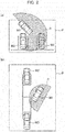
- a pedestrian W is shown as a symbol.
- information such as the attribute of the pedestrian P (whether the pedestrian P is an elderly person or a child) and the direction of eye of the pedestrian P may be lost.
- the attention-required object identification unit 47 identifies the pedestrian W detected by the object detector 60 as an attention-required object, and the camera image creation unit 45 creates a camera image of the pedestrian W identified, as illustrated in Fig. 8 .
- the synthesis unit 46 replaces the pedestrian W on the virtual image P with the camera image.
- a camera image of an attention-required object created may be a camera image of a region including the pedestrian W as illustrated in Fig. 8 , or a camera image cutting out the pedestrian W along the contour.
- the attention-required object identification unit 47 identifies the different vehicle M2 as an attention-required object, and the camera image creation unit 45 creates a camera image of the different vehicle M2.
- the following processing is the same as that described in connection to Fig. 8 , and will therefore not be described here.
- the object detector 60 detects different vehicles M2 and M3, a pedestrian W, bicycles B1 to B3, and a road sign L
- the attention-required object identification unit 47 identifies these objects as attention-required objects
- the camera image creation unit 45 creates camera images of these objects. The following processing is the same as that described in connection to Fig. 8 , and will therefore not be described here.
- Step S201 the environment detector 10 and the object detector 60 acquire information about the surroundings of the host vehicle.
- Step S202 the virtual image creation unit 41 creates a virtual image using the information about the surroundings of the host vehicle.
- Step S203 the attention-required object identification unit 47 identifies an attention-required object around the host vehicle.
- Step S204 the camera image creation unit 45 creates a camera image of the attention-required object identified by the attention-required object identification unit 47.
- Step S205 the synthesis unit 46 replaces the attention-required object on the virtual image with the camera image.
- Step S206 the controller 40 displays the synthesized image synthesized by the synthesis unit 46 on the display 50.
- the mobile body surroundings display apparatus 2 according to the second embodiment as described above produce the following advantageous effects.
- the mobile body surroundings display apparatus 2 first creates a virtual image using information about the surroundings of the host vehicle. Next, the mobile body surroundings display apparatus 2 identifies an attention-required object and creates a camera image of the attention-required object identified. Then, the mobile body surroundings display apparatus 1 replaces the attention-required object on the virtual image with the camera image, and displays the thus-synthesized image on the display 50. Thereby, an occupant can be informed of detailed information on the attention-required object.
- information on an attention-required object may be lost.
- a human is shown as a symbol
- information such as the attribute of that person (whether the person is an elderly person or a child) and the direction of eye of the person may be lost.
- a vehicle is shown as a symbol
- information such as the size, shape, and color of the vehicle may be lost.
- the mobile body surroundings display apparatus 2 displays an attention-required object on a virtual image after replacing it with a camera image, and thus can compensate for the loss of information which may be caused by image virtualization. Thereby, an occupant is more likely able to predict the motion of the attention-required object.
- the mobile body surroundings display apparatus 2 can inform an occupant with detailed information on an attention-required object, such as a pedestrian, an animal, a bicycle, a vehicle, or a road sign, by displaying the attention-required object after replacing the attention-required object with a camera image.
- an attention-required object such as a pedestrian, an animal, a bicycle, a vehicle, or a road sign
- the mobile body surroundings display apparatus 3 differs from the first embodiment in that the mobile body surroundings display apparatus 3 includes the object detector 60, the attention-required object identification unit 47, and a highlight portion identification unit 48.
- the same constituents as those in the first embodiment are denoted by the same reference numerals as used in the first embodiment, and are not described below. Different points will be mainly discussed below. Note that the object detector 60 and the attention-required object identification unit 47 are the same as those described in the second embodiment, and will therefore not be described below.
- the highlight portion identification unit 48 identifies a highlight portion to which an occupant needs to pay attention. Specifically, when an attention-required object identified by the attention-required object identification unit 47 is located within an attention-required range identified by the attention-required range identification unit 43, the highlight portion identification unit 48 identifies this attention-required object as a highlight portion. The highlight portion identification unit 48 outputs the identified highlight portion to the camera image creation unit 45 and the synthesis unit 46.
- An attention-required range for a case of a T intersection is, as indicated by the region R, a region around the host vehicle including a range of the left and right sides of the center of the T intersection.
- the attention-required range identification unit 43 identifies the region R as an attention-required range.
- the attention-required object identification unit 47 identifies different vehicles M2 and M3, a pedestrian W, bicycles B1 to B3, and a road sign L detected by the object detector 60, as attention-required objects.
- the highlight portion identification unit 48 identifies an attention-required object located within the range R as a highlight portion.
- the highlight portion identification unit 48 identifies the pedestrian W, the bicycles B1 to B3, and the road sign L as highlight portions.
- the camera image creation unit 45 creates camera images of the pedestrian W, the bicycles B1 to B3, and the road sign L identified as the highlight portions.
- the synthesis unit 46 replaces the pedestrian W, the bicycles B1 to B3, and the road sign L on a virtual image P with the camera images.
- the display 50 displays the pedestrian W, the bicycles B1 to B3, and the road sign L by use of the camera images, i.e., actual captured images.
- This allows an occupant to be informed of detailed information on the pedestrian W, the bicycles B1 to B3, and the road sign L.
- an attention-required object which is partially located within the region R such as the bicycles B2 and B3, is also identified as a highlight portion, but only an attention-required object which is entirely located within the region R may be identified as a highlight portion.
- the attention-required range identification unit 43 may identify an attention-required range in real time, and attention-required ranges may be preset on a map or the like.
- the highlight portion identification unit 48 does not identify any highlight portion when no attention-required object is detected within the region R.
- the synthesis unit 46 does not replace the region R on the virtual image P with a camera image.
- the reason for this is that when no attention-required object, such as a different vehicle or a pedestrian, is detected in a region R, the risk of the host vehicle colliding is low, and there is low necessity of informing an occupant of the region R which has been replaced with a camera image.
- the mobile body surroundings display apparatus 3 displays only the virtual image P and thus can reduce the amount of information given to an occupant. Consequently, the mobile body surroundings display apparatus 3 can bother an occupant less.
- the object detector 60 may detect an object within an attention-required range identified by the attention-required range identification unit 43. Such limitation of the range to detect an object in can reduce the time it takes for the object detector 60 to detect an object. In turn, the time it takes for the attention-required object identification unit 47 to identify an attention-required object can be reduced, as well. In addition, the limitation of the range to detect an object in can lead to reduction in the processing load on the controller 40.
- An attention-required range for a case of taking a left turn at an intersection is, as indicated with the region R, the entire region of the intersection, including the travelling direction (left-turn direction) of the host vehicle M1.
- the attention-required range identification unit 43 identifies the region R as an attention-required range
- the attention-required object identification unit 47 identifies different vehicles M2 to M4, a bicycle B, and a traffic light S as attention-required objects.
- the highlight portion identification unit 48 identifies an attention-required object located within the region R as a highlight portion.
- the highlight portion identification unit 48 identifies the different vehicles M2 to M4, the bicycle B, and the traffic light S as attention-required objects.
- the following processing is the same as that described in connection to Fig. 13 , and will therefore not be described here. Note that as depicted in Fig. 14 , the attention-required range can be set to suit a turning-left situation.
- the attention-required range identification unit 43 can set an attention-required range suitable for a travelling scene and a driving operation, and can make it less likely that attention is paid to the outside of the attention-required range.
- An attention-required range for a case of taking a right turn at an intersection is, as indicated with the region R, the entire region of the intersection including the travelling direction (right-turn direction) of the host vehicle M1 and excluding the right side of the host vehicle.
- the attention-required range identification unit 43 identifies the region R as an attention-required range
- the attention-required object identification unit 47 identifies different vehicles M2 to M4, a pedestrian W, bicycles B1 and B2, and road signs L1 and L2 as attention-required objects.
- the highlight portion identification unit 48 identifies an attention-required object located within the region R as a highlight portion.
- the highlight portion identification unit 48 identifies the different vehicles M2 to M4, the pedestrian W, the bicycles B1 and B2, and the road signs L1 and L2 as attention-required objects.
- the following processing is the same as that described in connection to Fig. 13 , and will therefore not be described here.
- the attention-required range identification unit 43 may set the attention-required range to suit a turning-right situation, as depicted in Fig. 15 .
- This flowchart is initiated when, for example, an ignition switch is turned on.
- Step S301 the environment detector 10, the object detector 60, and the vehicle cameras 20 to 23 acquire information about the surroundings of the host vehicle.
- Step S302 the virtual image creation unit 41 creates a virtual image using the information about the surroundings of the host vehicle.
- Step S303 the driving scene determination unit 42 determines a driving scene using the information about the surroundings of the host vehicle.
- Step S304 based on the driving scene determined by the driving scene determination unit 42, the attention-required range identification unit 43 identifies an attention-required range using the database in the storage unit 44.
- Step S305 the attention-required object identification unit 47 identifies an attention-required object around the host vehicle.
- Step S306 the highlight portion identification unit 48 determines whether an attention-required object is located within the attention-required range. When an attention-required object is located within the attention-required range (Yes in Step S306), the highlight portion identification unit 48 identifies the attention-required object located within the attention-required range, and the processing proceeds to Step S307. When no attention-required object is located within the attention-required range (No in Step S306), the processing proceeds to Step S310.
- Step S307 the camera image creation unit 45 creates a camera image of the attention-required object identified by the highlight portion identification unit 48.
- Step S308 the synthesis unit 46 replaces the attention-required object on the virtual image with the camera image.
- Step S309 the controller 40 displays the synthesized image synthesized by the synthesis unit 46 on the display 50.
- Step S310 the controller 40 displays the virtual image on the display 50.
- the mobile body surroundings display apparatus 3 according to the third embodiment as described above can produce the following advantageous effects.
- the mobile body surroundings display apparatus 3 first creates a virtual image using information about the surroundings of the host vehicle. Next, the mobile body surroundings display apparatus 3 identifies an attention-required range based on a driving scene and identifies an attention-required object within the attention-required range. The mobile body surroundings display apparatus 3 creates a camera image of the attention-required object within the attention-required range, replaces the attention-required object within the attention-required range on the virtual image with the camera image, and displays the thus-synthesized image on the display 50. Thereby, an occupant can be informed of detailed information on the attention-required object.
- the mobile body surroundings display apparatus 3 displays only the virtual image on the display 50 when no attention-required object is located within the attention-required range.
- the mobile body surroundings display apparatus 3 can reduce the amount of information given to an occupant.
- the mobile body surroundings display apparatus 3 can thus bother an occupant less.
- an attention-required range and an attention-required object are replaced with a camera image.
- an attention-required object is replaced with a camera image if the attention-required object is located within an attention-required range.
- An attention-required range and an attention-required object indicate a range to which an occupant needs to pay attention, and an attention-required range and an attention-required object can collectively be rephrased as an attention-required range.
- an attention-required range can also include a region the level of attention of which is equal to or above a predetermined value.
- an attention-required range is replaced with a camera image, but the present invention is not limited to this.
- the mobile body surroundings display apparatuses 1 to 3 may calculate a level of attention for the host vehicle and perform the replacement according to the level of attention calculated.
- the level of attention for the host vehicle can be obtained based on a relative speed or a relative distance to the host vehicle.
- the environment detector 10 and/or the object detector 60 may have the capability of detecting a relative speed and a relative distance to the host vehicle.
- the mobile body surroundings display apparatuses 1 to 3 may calculate and set a level of attention such that the higher the relative speed to the host vehicle, the higher the level of attention. Further, the mobile body surroundings display apparatuses 1 to 3 may set a level of attention such that the shorter the relative distance to the host vehicle, the higher the level of attention.
- the mobile body surroundings display apparatuses 1 to 3 calculate a level of attention of an object located around the host vehicle, and when the level of attention calculated is equal to or above a predetermined value, create a camera image of a region where the object is located, replace that region on a virtual image with the camera image, and display the thus-synthesized image. Thereby, the mobile body surroundings display apparatuses 1 to 3 can inform an occupant of detailed information on a region to which attention needs to be paid, without identifying the attribute of the object (whether the object is a human or an animal) or the like.
- the predetermined value can be obtained beforehand through experiment or simulation.
- the mobile body surroundings display apparatuses 1 to 3 may divide a virtual image into a plurality of parts, calculate a level of attention for each of regions corresponding to the respective divided parts of the image, and replace a region the calculated level of attention of which is equal to or above a predetermined value with a camera image. This way, the mobile body surroundings display apparatuses 1 to 3 can reduce the load for the attention level calculation.
- the attention-required range identification unit 43 identifies an attention-required range using a databased stored in the storage unit 44
- the present invention is not limited to this.
- the attention-required range identification unit 43 may transmit information on the position of the host vehicle to a cloud, and identify an attention-required range using information from the cloud corresponding to the information on the position of the host vehicle.
- the attention-required range identification unit 43 may identify an attention-required range using information acquired from a different vehicle through vehicle-to-vehicle communication.
- the synthesis unit 46 of the present embodiments replaces an attention-required range on a virtual image with a camera image
- the present invention is not necessarily limited to this.
- the synthesis unit 46 may generate a camera image around the host vehicle and replace a region other than an attention-required range with a virtual image. In other words, any approach may be implemented as long as an attention-required range is displayed by use of a camera image.
- a processing circuit includes a programmed processing device such as a processing device including an electric circuit.
- a processing circuit includes a device such as an application-specific integrated circuit (ASIC) adapted to execute functions described in the embodiments or a conventional circuit component.
- ASIC application-specific integrated circuit
Landscapes
- Engineering & Computer Science (AREA)
- Multimedia (AREA)
- Mechanical Engineering (AREA)
- Signal Processing (AREA)
- Physics & Mathematics (AREA)
- General Physics & Mathematics (AREA)
- Remote Sensing (AREA)
- Radar, Positioning & Navigation (AREA)
- Chemical & Material Sciences (AREA)
- Combustion & Propulsion (AREA)
- Transportation (AREA)
- Traffic Control Systems (AREA)
- Closed-Circuit Television Systems (AREA)
- Image Processing (AREA)
- Image Analysis (AREA)
Applications Claiming Priority (1)
| Application Number | Priority Date | Filing Date | Title |
|---|---|---|---|
| PCT/JP2016/062014 WO2017179174A1 (fr) | 2016-04-14 | 2016-04-14 | Procédé d'affichage d'environnement de corps mobile et appareil d'affichage d'environnement de corps mobile |
Publications (2)
| Publication Number | Publication Date |
|---|---|
| EP3444145A1 true EP3444145A1 (fr) | 2019-02-20 |
| EP3444145A4 EP3444145A4 (fr) | 2019-08-14 |
Family
ID=60042543
Family Applications (1)
| Application Number | Title | Priority Date | Filing Date |
|---|---|---|---|
| EP16898634.7A Ceased EP3444145A4 (fr) | 2016-04-14 | 2016-04-14 | Procédé d'affichage d'environnement de corps mobile et appareil d'affichage d'environnement de corps mobile |
Country Status (10)
| Country | Link |
|---|---|
| US (1) | US10864856B2 (fr) |
| EP (1) | EP3444145A4 (fr) |
| JP (1) | JP6555413B2 (fr) |
| KR (1) | KR102023863B1 (fr) |
| CN (1) | CN109070799B (fr) |
| BR (1) | BR112018071020B1 (fr) |
| CA (1) | CA3020813C (fr) |
| MX (1) | MX367700B (fr) |
| RU (1) | RU2715876C1 (fr) |
| WO (1) | WO2017179174A1 (fr) |
Families Citing this family (2)
| Publication number | Priority date | Publication date | Assignee | Title |
|---|---|---|---|---|
| JP7195200B2 (ja) * | 2019-03-28 | 2022-12-23 | 株式会社デンソーテン | 車載装置、車載システムおよび周辺監視方法 |
| US11554668B2 (en) * | 2019-06-25 | 2023-01-17 | Hyundai Mobis Co., Ltd. | Control system and method using in-vehicle gesture input |
Family Cites Families (19)
| Publication number | Priority date | Publication date | Assignee | Title |
|---|---|---|---|---|
| JPH06278531A (ja) | 1993-03-25 | 1994-10-04 | Honda Motor Co Ltd | 車両用視認補助装置 |
| JP4334686B2 (ja) | 1999-07-07 | 2009-09-30 | 本田技研工業株式会社 | 車両の画像表示装置 |
| JP4956915B2 (ja) * | 2005-05-20 | 2012-06-20 | 日産自動車株式会社 | 映像表示装置及び映像表示方法 |
| BRPI0613097B1 (pt) | 2005-06-30 | 2019-01-22 | Agc Flat Glass Na Inc | dispositivo e método de reconhecimento de imagem |
| JP4775123B2 (ja) | 2006-06-09 | 2011-09-21 | 日産自動車株式会社 | 車両用監視装置 |
| WO2008137708A1 (fr) * | 2007-05-04 | 2008-11-13 | Gesturetek, Inc. | Entrée utilisateur basée sur caméra pour dispositifs compacts |
| US8947421B2 (en) * | 2007-10-29 | 2015-02-03 | Interman Corporation | Method and server computer for generating map images for creating virtual spaces representing the real world |
| JP2011118482A (ja) * | 2009-11-30 | 2011-06-16 | Fujitsu Ten Ltd | 車載装置および認知支援システム |
| CN102714710B (zh) * | 2009-12-07 | 2015-03-04 | 歌乐牌株式会社 | 车辆周边图像显示系统 |
| JP2011205513A (ja) * | 2010-03-26 | 2011-10-13 | Aisin Seiki Co Ltd | 車両周辺監視装置 |
| WO2011135778A1 (fr) * | 2010-04-26 | 2011-11-03 | パナソニック株式会社 | Dispositif de traitement d'image, système de navigation de voiture et système de caméras sur rue |
| JP2012053533A (ja) * | 2010-08-31 | 2012-03-15 | Daihatsu Motor Co Ltd | 運転支援装置 |
| JP5998496B2 (ja) | 2011-02-02 | 2016-09-28 | 日産自動車株式会社 | 駐車支援装置 |
| US20120287277A1 (en) * | 2011-05-13 | 2012-11-15 | Koehrsen Craig L | Machine display system |
| WO2014109016A1 (fr) * | 2013-01-09 | 2014-07-17 | 三菱電機株式会社 | Dispositif d'affichage de périphérie de véhicule |
| JP2013255237A (ja) * | 2013-07-08 | 2013-12-19 | Alpine Electronics Inc | 画像表示装置及び画像表示方法 |
| JP5901593B2 (ja) * | 2013-09-11 | 2016-04-13 | 本田技研工業株式会社 | 車両用表示装置 |
| US20150138099A1 (en) * | 2013-11-15 | 2015-05-21 | Marc Robert Major | Systems, Apparatus, and Methods for Motion Controlled Virtual Environment Interaction |
| US9639968B2 (en) | 2014-02-18 | 2017-05-02 | Harman International Industries, Inc. | Generating an augmented view of a location of interest |
-
2016
- 2016-04-14 JP JP2018511838A patent/JP6555413B2/ja active Active
- 2016-04-14 BR BR112018071020-2A patent/BR112018071020B1/pt active IP Right Grant
- 2016-04-14 CN CN201680084502.4A patent/CN109070799B/zh active Active
- 2016-04-14 KR KR1020187030092A patent/KR102023863B1/ko active IP Right Grant
- 2016-04-14 MX MX2018012119A patent/MX367700B/es active IP Right Grant
- 2016-04-14 WO PCT/JP2016/062014 patent/WO2017179174A1/fr active Application Filing
- 2016-04-14 US US16/092,334 patent/US10864856B2/en active Active
- 2016-04-14 RU RU2018139676A patent/RU2715876C1/ru active
- 2016-04-14 EP EP16898634.7A patent/EP3444145A4/fr not_active Ceased
- 2016-04-14 CA CA3020813A patent/CA3020813C/fr active Active
Also Published As
| Publication number | Publication date |
|---|---|
| KR20180123553A (ko) | 2018-11-16 |
| US10864856B2 (en) | 2020-12-15 |
| BR112018071020B1 (pt) | 2022-06-28 |
| CN109070799B (zh) | 2021-02-26 |
| CA3020813A1 (fr) | 2017-10-19 |
| BR112018071020A2 (pt) | 2019-02-12 |
| US20190337455A1 (en) | 2019-11-07 |
| CA3020813C (fr) | 2019-05-14 |
| JPWO2017179174A1 (ja) | 2019-04-04 |
| KR102023863B1 (ko) | 2019-09-20 |
| RU2715876C1 (ru) | 2020-03-03 |
| JP6555413B2 (ja) | 2019-08-14 |
| WO2017179174A1 (fr) | 2017-10-19 |
| MX367700B (es) | 2019-09-03 |
| CN109070799A (zh) | 2018-12-21 |
| MX2018012119A (es) | 2019-02-11 |
| EP3444145A4 (fr) | 2019-08-14 |
Similar Documents
| Publication | Publication Date | Title |
|---|---|---|
| US11535155B2 (en) | Superimposed-image display device and computer program | |
| US9589194B2 (en) | Driving assistance device and image processing program | |
| CN109515434B (zh) | 车辆控制装置、车辆控制方法及存储介质 | |
| CA3002628C (fr) | Procede de commande d'affichage et dispositif de commande d'affichage | |
| EP3487172A1 (fr) | Dispositif de génération d'images, procédé de génération d'images, et programme | |
| US9469248B2 (en) | System and method for providing situational awareness in a vehicle | |
| CN105608927A (zh) | 警告装置 | |
| CN111595357B (zh) | 可视化界面的显示方法、装置、电子设备和存储介质 | |
| CN104691447A (zh) | 用于动态地聚焦车辆传感器的系统和方法 | |
| JP2024023319A (ja) | 緊急車両の検出 | |
| US20190244515A1 (en) | Augmented reality dsrc data visualization | |
| CN108604413B (zh) | 显示装置的控制方法及显示装置 | |
| JP7011559B2 (ja) | 表示装置、表示制御方法、およびプログラム | |
| US11104356B2 (en) | Display device and method for a vehicle | |
| CN109927629B (zh) | 用于控制投影设备的显示控制设备、显示控制方法及车辆 | |
| CN111936364B (zh) | 停车辅助装置 | |
| CA3020813C (fr) | Procede d'affichage d'environnement de corps mobile et appareil d'affichage d'environnement de corps mobile | |
| JP6102509B2 (ja) | 車両用表示装置 | |
| US11545035B2 (en) | Driver notification system | |
| JP2021149319A (ja) | 表示制御装置、表示制御方法およびプログラム | |
| JP6824809B2 (ja) | 走行支援装置、撮像システム、車両、及び走行支援システム | |
| JP3222638U (ja) | 安全運転支援装置 | |
| JP7427556B2 (ja) | 運転制御装置、運転制御方法及びプログラム | |
| JP6989418B2 (ja) | 車載システム | |
| JP7259377B2 (ja) | 車両用表示装置、車両、表示方法及びプログラム |
Legal Events
| Date | Code | Title | Description |
|---|---|---|---|
| STAA | Information on the status of an ep patent application or granted ep patent |
Free format text: STATUS: THE INTERNATIONAL PUBLICATION HAS BEEN MADE |
|
| PUAI | Public reference made under article 153(3) epc to a published international application that has entered the european phase |
Free format text: ORIGINAL CODE: 0009012 |
|
| STAA | Information on the status of an ep patent application or granted ep patent |
Free format text: STATUS: REQUEST FOR EXAMINATION WAS MADE |
|
| 17P | Request for examination filed |
Effective date: 20181109 |
|
| AK | Designated contracting states |
Kind code of ref document: A1 Designated state(s): AL AT BE BG CH CY CZ DE DK EE ES FI FR GB GR HR HU IE IS IT LI LT LU LV MC MK MT NL NO PL PT RO RS SE SI SK SM TR |
|
| AX | Request for extension of the european patent |
Extension state: BA ME |
|
| DAV | Request for validation of the european patent (deleted) | ||
| DAX | Request for extension of the european patent (deleted) | ||
| A4 | Supplementary search report drawn up and despatched |
Effective date: 20190712 |
|
| RIC1 | Information provided on ipc code assigned before grant |
Ipc: G08G 1/16 20060101ALI20190708BHEP Ipc: H04N 7/18 20060101ALI20190708BHEP Ipc: B60R 1/00 20060101AFI20190708BHEP |
|
| STAA | Information on the status of an ep patent application or granted ep patent |
Free format text: STATUS: EXAMINATION IS IN PROGRESS |
|
| 17Q | First examination report despatched |
Effective date: 20200423 |
|
| STAA | Information on the status of an ep patent application or granted ep patent |
Free format text: STATUS: EXAMINATION IS IN PROGRESS |
|
| REG | Reference to a national code |
Ref country code: DE Ref legal event code: R003 |
|
| STAA | Information on the status of an ep patent application or granted ep patent |
Free format text: STATUS: THE APPLICATION HAS BEEN REFUSED |
|
| 18R | Application refused |
Effective date: 20210504 |